ESPRESSIF SYSTEMS ESPWROOM02UC Wi-Fi Internet of Things Module User Manual ESP WROOM 02UC Datasheet EN pages
ESPRESSIF SYSTEMS (SHANGHAI) PTE LTD Wi-Fi Internet of Things Module ESP WROOM 02UC Datasheet EN pages
User Manual

www.espressif.com
Version 0.1
Espressif Systems
Copyright © 2018
ESP-WROOM-02UC
Datasheet

About This Guide
This document provides introduction to the specifications of ESP-WROOM-02UC
hardware.
Release Notes
Documentation Change Notification
Espressif provides email notifications to keep customers updated on changes to
technical documentation. Please subscribe at https://www.espressif.com/en/subscribe.
Certification
Download certificates for Espressif products from https://www.espressif.com/en/
certificates.
Date
Version
Release notes
2018.10
V0.1
For certification only.

Table of Contents
1. Overview 1................................................................................................................................
2. Pin Description 3......................................................................................................................
3. Functional Description 5..........................................................................................................
3.1. CPU!5"..........................................................................................................................................
3.2. Memory!5"....................................................................................................................................
3.2.1. Internal SRAM and ROM!5"...........................................................................................
3.2.2. SPI Flash!5"....................................................................................................................
3.3. Crystal Oscillator!6"......................................................................................................................
3.4. Interface Description!6"................................................................................................................
4. Electrical Characteristics 8......................................................................................................
4.1. Electrical Characteristics!8"..........................................................................................................
4.2. Wi-Fi Radio!8"...............................................................................................................................
4.3. Power Consumption!9".................................................................................................................
4.4. Reflow Profile!10".........................................................................................................................
4.5. Electrostatic Discharge!11"..........................................................................................................
5.Dimensions ...........................................................................................................................12
6. Recommended PCB Land Pattern ......................................................................................13
A. Appendix—Learning Resources .........................................................................................14
A.1. Must-Read Documents
"..........................................................................................................14"
A.2. Must-Have Resources"............................................................................................................15

CONFIDENTIAL
!
1. Overview
1. Overview
ESP-WROOM-02UC is ESP8266EX-based module developed by Espressif. Compared to
ESP-WROOM-02U, a two-layer PCB design is applied for ESP-WROOM-02UC.
Table 1-1 provides the specifications of ESP-WROOM-02UC.
📖 Note:
For more information on ESP8266EX, please refer to ESP8266EX Datasheet.
Table 1-1. ESP-WROOM-02UC Specifications
Categories
Items
Specifications
Wi-Fi
Wi-Fi protocols
802.11 b/g/n20
Frequency range
2412MHz-2462MHz
Hardware
Peripheral interface
UART/HSPI/I2C/I2S/IR Remote Control
GPIO/PWM
Operating voltage
2.7V ~ 3.6V
Operating current
Average: 80 mA
Minimum current delivered by
power supply
500 mA
Operating temperature range
-40°C ~ 85°C
External interface
-
Software
Wi-Fi mode
Station/SoftAP/SoftAP + Station
Security
WPA/WPA2
Encryption
WEP/TKIP/AES
Firmware upgrade
UART Download/OTA (via network)/Download and write
firmware via host
Software development
Supports Cloud Server Development/SDK for custom
firmware development
Network protocols
IPv4, TCP/UDP/HTTP/FTP
User configuration
AT Instruction Set, Cloud Server, Android/iOS app
Espressif
!1/!15
2018.10
CONFIDENTIAL
!
1. Overview
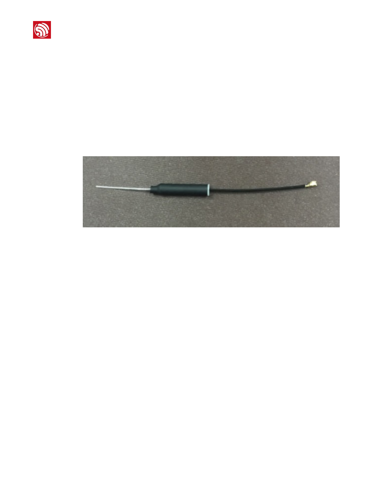
The IPEX antenna supported on ESP-WROOM-02UC has the following specifications:
•
Frequency range: 2412MHz-2462MHz
• Bandwidth: 100 MHz
• Input impedance: 50 Ω
• VSWR: <2.5
• Gain: >1.0 dBi
• Polarization type: Vertical
Figure 1-1 shows the IPEX antenna.
!
Figure 1-1. ESP-WROOM-02UC Reflow Profile
Espressif
!2/!15
2018.10
!
2. Pin Description
2. Pin Description
!
Table 2-1. ESP-WROOM-02UC Pin Definitions
No.
Pin Name
Functional Description
1
3V3
3.3V power supply (VDD)
📖 Note:
It is recommended the maximum output current a power supply
provides be of 500 mA or above.
2
EN
Chip enable pin. Active high.
3
IO14
GPIO14; HSPI_CLK
4
IO12
GPIO12; HSPI_MISO
Espressif
!3/!15
2018.10
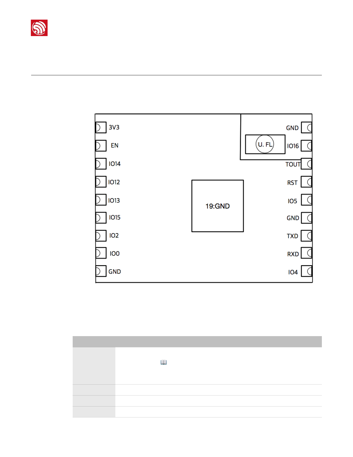
Figure 2-1 shows the pin distribution of the ESP-WROOM-02UC.
Figure 2-1. ESP-WROOM-02UC Pin Layout (Top View)
ESP-WROOM-02UC has 18 pins. Please see the pin definitions in Table 2-1.

CONFIDENTIAL
!
2. Pin Description
5
IO13
GPIO13; HSPI_MOSI; UART0_CTS
6
IO15
GPIO15; MTDO; HSPICS; UART0_RTS
Pull down.
7
IO2
GPIO2; UART1_TXD
Floating (internal pull-up) or pull up.
8
IO0
GPIO0
•UART download: pull down.
•Flash boot: floating or pull up.
9
GND
GND
10
IO4
GPIO4
11
RXD
UART0_RXD, receive end in UART download;
GPIO3
12
TXD
UART0_TXD, transmit end in UART download, floating or pull up;
GPIO1
13
GND
GND
14
IO5
GPIO5
15
RST
Reset
16
TOUT
It can be used to test the power-supply voltage of VDD3P3 (Pin3 and
Pin4) and the input power voltage of TOUT (Pin6). These two functions
cannot be used simultaneously.
17
IO16
GPIO16; used for Deep-sleep wake-up when connected to RST pin.
18
GND
GND
No.
Pin Name
Functional Description
Espressif
!4/!15
2018.10

CONFIDENTIAL
!
3. Functional Description
3. Functional Description
3.1. CPU
The ESP8266EX integrates a Tensilica L106 32-bit RISC processor, which achieves extra-
low power consumption and reaches a maximum clock speed of 160 MHz. The Real-Time
Operating System (RTOS) and Wi-Fi stack allow 80% of the processing power to be
available for user application programming and development. The CPU includes the
interfaces as below:
•Programmable RAM/ROM interfaces (iBus), which can be connected with memory
controller, and can also be used to visit flash.
•Data RAM interface (dBus), which can connected with memory controller.
•AHB interface which can be used to visit the register.
3.2. Memory
3.2.1. Internal SRAM and ROM
ESP8266EX Wi-Fi SoC integrates the memory controller and memory units including ROM
and SRAM. MCU can access the memory units through iBus, dBus, and AHB interfaces.
All memory units can be accessed upon request. A memory arbiter determines the running
sequence in the arrival order of requests.
According to our current version of SDK, the SRAM space available to users is assigned as
follows:
•RAM size < 50 kB, that is, when ESP8266EX is working in Station mode and
connects to the router, available space in the Heap + Data sector is around 50 kB.
•There is no programmable ROM in ESP8266EX, therefore, the user program must be
stored in an external SPI flash.
3.2.2. SPI Flash
ESP8266EX supports SPI flash. Theoretically speaking, ESP8266EX can support an up-
to-16-MB SPI flash.
ESP-WROOM-02UC currently integrates a 2-MB SPI flash and supports these SPI modes:
Standard SPI, DIO (Dual I/O), DOUT (Dual Output), QIO (Quad I/O) and QOUT (Quad
Output).
Espressif
!5/!15
2018.10

CONFIDENTIAL
!
3. Functional Description
3.3. Crystal Oscillator
ESP-WROOM-02UC uses a 26-MHz crystal oscillator. The accuracy of the crystal oscillator
should be ±10 PPM.
When using the download tool, please select the right type of crystal oscillator. In circuit
design, capacitors C1 and C2 which connect to the earth are added to the input and
output terminals of the crystal oscillator respectively. The values of the two capacitors can
be flexible, ranging from 6 pF to 22 pF, however, the specific capacitive values depend on
further testing of, and adjustment to, the overall performance of the whole circuit. Normally,
the capacitive values of C1 and C2 are within 10 pF for the 26-MHz crystal oscillator.
3.4. Interface Description
Table 3-1. Interface Description
Interface
Pin
Functional Description
HSPI
IO12 (MISO), IO13
(MOSI), IO14 (CLK),
IO15 (CS)
Connects to SPI Flash, display screen, and MCU.
PWM
IO12 (R), IO15
(G),IO13 (B)
Currently the PWM interface has four channels, but users can extend it
to eight channels. PWM interface can realize the control of LED lights,
buzzers, relays, electronic machines, etc.
IR
IO14 (IR_T), IO5
(IR_R)
The functionality of the infrared remote control interface can be realized
via software programming. The interface uses NEC coding, modulation,
and demodulation. The frequency of the modulated carrier signal is 38
kHz.
ADC
TOUT
Tests the power supply voltage of VDD3P3 (Pin3 and Pin4) and the input
power voltage of TOUT (Pin6). However, these two functions cannot be
used simultaneously. This interface is typically used in sensors.
I2C
IO14 (SCL), IO2 (SDA)
Connects to external sensors and display screens, etc.
UART
UART0: TXD
(U0TXD),
RXD (U0RXD), IO15
(RTS), IO13 (CTS)
UART1: IO2 (TXD)
Communicates with the UART device.
Downloading: U0TXD + U0RXD or GPIO2 + U0RXD
Communicating: (UART0): U0TXD, U0RXD, MTDO (U0RTS), MTCK
(U0CTS)
Debugging: UART1_TXD (GPIO2) can be used to print debugging
information.
By default, UART0 will output some printed information when you power
on ESP8266EX. If this issue influences some specific applications, users
can exchange the inner pins of UART when initializing ESP8266EX, that
is, exchange U0TXD and U0RXD with U0RTS and U0CTS. Users can
connect MTDO and MTCK to the serial port of the external MCU to
realize the communication.
Espressif
!6/!15
2018.10

CONFIDENTIAL
!
3. Functional Description
I2S
I2S input:
IO12 (I2SI_DATA) ;
IO13 (I2SI_BCK );
IO14 (I2SI_WS);
Collects, processes and transmits audio data.
I2S output:
IO15 (I2SO_BCK );
IO3 (I2SO_DATA);
IO2 (I2SO_WS ).
Interface
Pin
Functional Description
Espressif
!7/!15
2018.10

!
4. Electrical Characteristics
4. Electrical Characteristics
4.1. Electrical Characteristics
4.2. Wi-Fi Radio
📖 Note:
Unless otherwise specified, measurements are based on VDD = 3.3V, TA = 25°C.
Table 4-1. Electrical Characteristics
Parameter
Symbol
Min
Typ
Max
Unit
Operating temperature
-
–40
20
85
℃
Maximum soldering temperature
(Condition: IPC/JEDEC J-STD-020)
-
-
-
260
℃
Supply voltage
VDD
2.7
3.3
3.6
V
Input logic level low
VIL
–0.3
-
0.25 VDD
V
Input logic level high
VIH
0.75 VDD
-
VDD + 0.3
V
Output logic level low
VOL
-
-
0.1 VDD
V
Output logic level high
VOH
0.8 VDD
-
-
V
Table 4-2. Wi-Fi Radio Characteristics
Description
Min
Typ
Max
Unit
Input frequency
2412
-
2462
MHz
Input reflection
-
-
–10
dB
Output Impedance
-
*
-
Ω
Output Power
RF Power 18.26 - 24.11 dBm
Sensitivity
DSSS, 1 Mbps - –98 - dBm
CCK, 11 Mbps - –91 - dBm
Espressif
!8/!15
2018.10

CONFIDENTIAL
!
4. Electrical Characteristics
4.3. Power Consumption
The following power consumption data were obtained from the tests with a 3.3V power
supply and a voltage stabilizer, in 25°C ambient temperature. All data are based on 50%
duty cycle in continuous transmission mode.
6 Mbps (1/2 BPSK)
-
–93
-
dBm
54 Mbps (3/4 64-QAM)
-
–75
-
dBm
HT20, MCS7 (65 Mbps, 72.2 Mbps)
-
–72
-
dBm
Adjacent channel rejection
OFDM, 6 Mbps
-
37
-
dB
OFDM, 54 Mbps
-
21
-
dB
HT20, MCS0
-
37
-
dB
HT20, MCS7
-
20
-
dB
Description
Min
Typ
Max
Unit
📖 Note:
For the module that uses an IPEX antenna, the output impedance is 50Ω.
Table 4-3. Power Consumption
Modes
Min
Typ
Max
Unit
Tx 802.11b, CCK 11 Mbps, POUT = +17 dBm
-
170
-
mA
Tx 802.11g, OFDM 54 Mbps, POUT = +15 dBm
-
140
-
mA
Tx 802.11n, MCS7, POUT = +13 dBm
-
120
-
mA
Rx 802.11b, 1024 bytes packet length , –80 dBm
-
50
-
mA
Rx 802.11g, 1024 bytes packet length , –70 dBm
-
56
-
mA
Rx 802.11n, 1024 bytes packet length , –65 dBm
-
56
-
mA
Modem-sleep①
-
15
-
mA
Light-sleep②
-
0.9
-
mA
Deep-sleep③
-
20
-
μA
Power Off
-
0.5
-
μA
Espressif
!9/!15
2018.10
CONFIDENTIAL
!
4. Electrical Characteristics
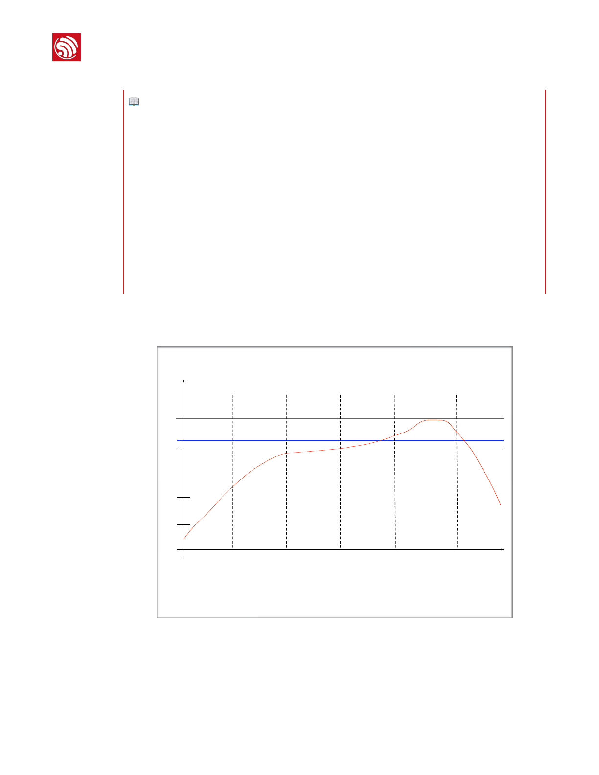
4.4. Reflow Profile
Figure 4-1. ESP-WROOM-02UC Reflow Profile
📖 Notes:
①Modem-sleep mode is used in the applications that require the CPU to be working, as in PWM or
I2S applications. According to 802.11 standards (like U-APSD), it shuts down the Wi-Fi Modem
circuit while maintaining a Wi-Fi connection with no data transmission to optimize power
consumption. E.g. in DTIM3, maintaining a sleep of 300 ms with a wakeup of 3 ms cycle to receive
AP’s Beacon packages at interval requires about 15 mA current.
②During Light-sleep mode, the CPU may be suspended in applications like Wi-Fi switch. Without
data transmission, the Wi-Fi Modem circuit can be turned off and CPU suspended to save power
consumption according to the 802.11 standards (U-APSD). E.g. in DTIM3, maintaining a sleep of
300 ms with a wakeup of 3ms to receive AP’s Beacon packages at interval requires about 0.9 mA
current.
③During Deep-sleep mode, Wi-Fi is turned off. For applications with long time lags between data
transmission, e.g. a temperature sensor that detects the temperature every 100s, sleeps for 300s
and wakes up to connect to the AP (taking about 0.3 ~ 1s), the overall average current is less than
1mA. The current of 20 μA is acquired at the voltage of 2.5V.
50 150
0
25
1 ~ 3℃/s
0
200
250
200
-1 ~ -5℃/s
Cooling zone
100
217
50
100 250
Reflow zone
!217℃ 60 ~ 90s
Temperature (℃)
Preheating zone
150 ~ 200℃ 60 ~ 120s
Ramp-up zone
Peak Temp.
235 ~ 250℃
Soldering time
> 30s
Time (sec.)
Ramp-up zone — Temp.: <150℃ Time: 60 ~ 90s Ramp-up rate: 1 ~ 3℃/s
Preheating zone — Temp.: 150 ~ 200℃ Time: 60 ~ 120s Ramp-up rate: 0.3 ~ 0.8℃/s
Reflow zone — Temp.: >217℃ 7LPH60 ~ 90s; Peak Temp.: 235 ~ 250℃ (<245℃ recommended) Time: 30 ~ 70s
Cooling zone — Peak Temp. ~ 180℃ Ramp-down rate: -1 ~ -5℃/s
Solder — Sn&Ag&Cu Lead-free solder (SAC305)
Espressif
!10/!15
2018.10

CONFIDENTIAL
!
4. Electrical Characteristics
4.5. Electrostatic Discharge
Table 4-4. Electrostatic Discharge Parameters
Name
Symb
ol
Reference
Level
Max
Unit
Electrostatic Discharge
(Human - Body Model)
VESD
(HBM)
Temperature: 23 ± 5℃
Based%on ANSI/ESDA/JEDEC JS - 001 - 2014
2
2000
V
Electrostatic Discharge
(Charged - Device
Model)
VESD
(CDM)
Temperature: 23 ± 5℃
Based%on JEDEC EIA/JESD22 - C101F
C2
500
Espressif
!11/!15
2018.10
CONFIDENTIAL
!
5.
Dimensions
5.
Dimensions
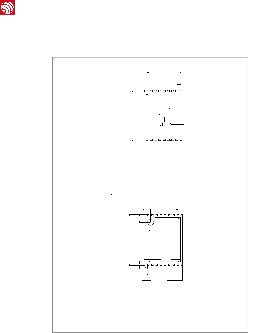
!
Figure5-1. ESP-WROOM-02UC Dimensions
PCB Thickness
Module Thickness
Module Length
Unit: mm
Module Width
3.20±0.10
0.80±0.10
18.00±0.10
14.30±0.10
12.00±0.10
1.50±0.10
ESP-WROOM-02UC DIMENSIONS
Top View Side View Bottom View
2.80±0.10
3.00±0.10
15.70±0.10
12.75±0.10
8.85±0.10
11.50±0.10
0.90±0.10
0.45±0.10
0.90±0.10
0.85±0.1
0.90±0.10
1.50±0.10
12.00±0.10
6.50±0.10
2.00±0.10
1.15±0.10
1.75±0.10
0.90±0.10
1.80±0.10
3.40±0.10
4.45±0.10
18.00±0.10
Espressif
!12/!15
2018.10
CONFIDENTIAL
!
6.
Recommended PCB Land Pattern
6.
Recommended PCB Land
Pattern
!
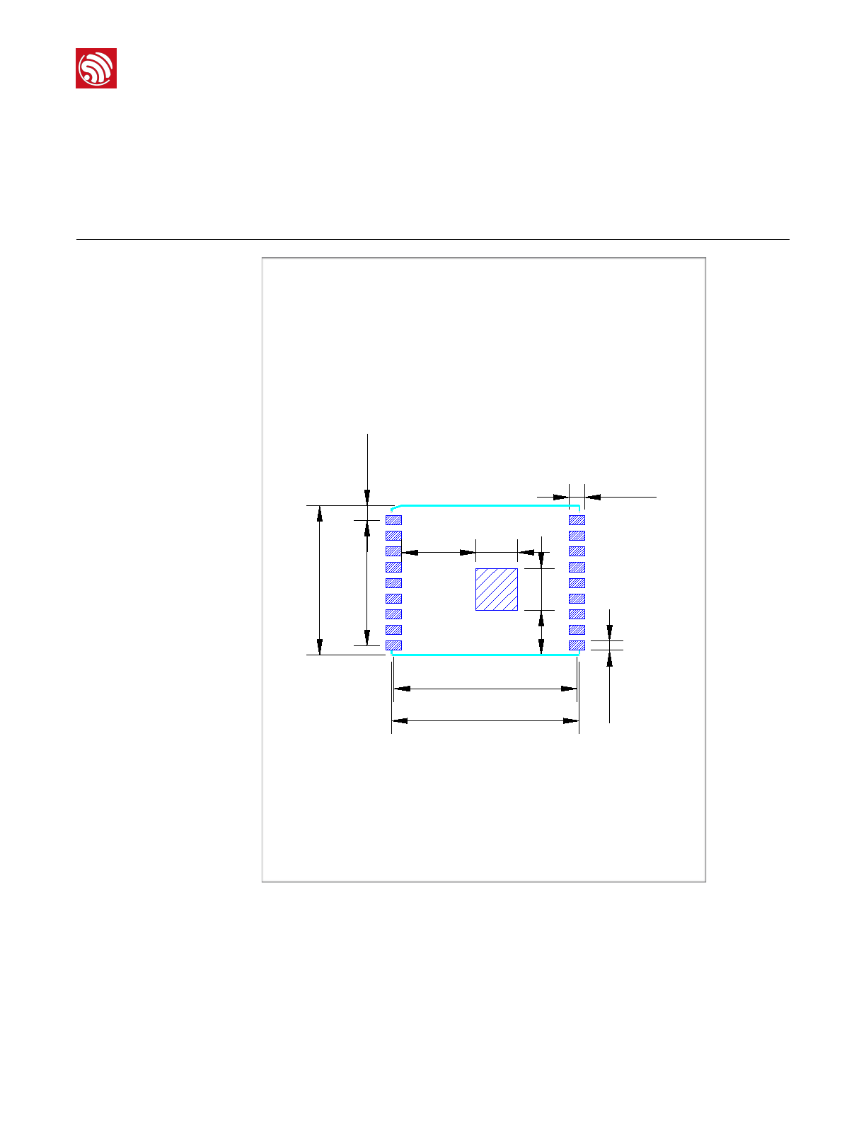
Figure 6-1. Recommended PCB Land Pattern of ESP-WROOM-02UC
Unit:mm
1.5x8=12
1.5
17.5
4
4.29
4
0.9
1
910
18
7.1
1.4
14.3
18
Espressif
!13/!15
2018.10

CONFIDENTIAL
!
Appendix A
A. Appendix—Learning
Resources
A.1. Must-Read Documents
•ESP8266 Quick Start Guide
Description: This document is a quick user guide to getting started with ESP8266. It
includes an introduction to the ESP-LAUNCHER, how to download firmware on to the
board and run it, how to compile the AT application, structure and the debugging
method of RTOS SDK. Basic documentation and other related resources for the
ESP8266 are also provided.
•ESP8266 SDK Getting Started Guide
Description: This document takes ESP-LAUNCHER and ESP-WROOM-02 as examples
to introduce how to use ESP8266 SDK. The contents include preparations before
compilation, SDK compilation and firmware download.
•ESP-WROOM-02 PCB Design and Module Placement Guide
Description: The ESP-WROOM-02 module is designed to be soldered to a host PCB.
This document compares six different placements of the antenna on a host board and
provides notes on designing PCB.
•ESP8266 Hardware Resources
Description: This zip package includes manufacturing specifications of the ESP8266
board and the modules, manufacturing BOM and schematics.
•ESP8266 AT Command Examples
Description: This document introduces some specific examples of using Espressif AT
commands, including single connection as a TCP Client, UDP transmission and
transparent transmission, and multiple connection as a TCP server.
•ESP8266 AT Instruction Set
Description: This document provides lists of AT commands based on
ESP8266_NONOS_SDK, including user-defined AT commands, basic AT commands,
Wi-Fi AT commands and TCP/IP-related AT commands. It also introduces the
downloading of AT firmware into flash.
•TCP/UDP UART Passthrough Test Demonstration
Description: This guide is intended to help users run a TCP & UDP passthrough test on
the ESP8266 IoT platform.
Espressif
!14/!15
2018.10

CONFIDENTIAL
!
Appendix A
•FAQ
A.2. Must-Have Resources
•ESP8266 SDKs
Description: This website page provides links to the latest version of ESP8266 SDK and
the older ones.
•ESP8266 Tools
Description: This website page provides links to the ESP8266 flash download tools and
ESP8266 performance evaluation tools.
•ESP8266 App
•ESP8266 Certification and Test Guide
•ESP8266 BBS
•ESP8266 Resources!
Espressif !15/!152018.10

Disclaimer and Copyright Notice
Information in this document, including URL references, is subject to change without
notice.
THIS DOCUMENT IS PROVIDED AS IS WITH NO WARRANTIES WHATSOEVER,
INCLUDING ANY WARRANTY OF MERCHANTABILITY, NON-INFRINGEMENT, FITNESS
FOR ANY PARTICULAR PURPOSE, OR ANY WARRANTY OTHERWISE ARISING OUT
OF ANY PROPOSAL, SPECIFICATION OR SAMPLE.
All liability, including liability for infringement of any proprietary rights, relating to use of
information in this document is disclaimed. No licenses express or implied, by estoppel or
otherwise, to any intellectual property rights are granted herein.
The Wi-Fi Alliance Member logo is a trademark of the Wi-Fi Alliance. The Bluetooth logo is
a registered trademark of Bluetooth SIG.
All trade names, trademarks and registered trademarks mentioned in this document are
property of their respective owners, and are hereby acknowledged.
Copyright © 2018 Espressif Inc. All rights reserved.
Espressif IoT Team"
www.espressif.com
FCC Statement
Any Changes or modifications not expressly approved by the party responsible for
compliance could void the user’s authority to operate the equipment.
This device complies with part 15 of the FCC Rules. Operation is subject to the
following two conditions: (1) This device may not cause harmful interference, and (2)
This device must accept any interference received, including interference that may
cause undesired operation.
FCC Radiation Exposure Statement:
This equipment complies with FCC radiation exposure limits set forth for an
uncontrolled environment .This equipment should be installed and operated with
minimum distance 20cm between the radiator& your body.
FCC Label Instructions
The outside of final products that contains this module device must display a label
referring to the enclosed module. This exterior label can use wording such as:
“Contains Transmitter Module FCC ID:2AC7Z-ESPWROOM02UC" or “Contains
FCC ID:2AC7Z-ESPWROOM02UC” Any similar wording that expresses the same
meaning may be used.