EUROTECH MRG1005 Multi-Service Gateway & Edge Controller User Manual ReliaGATE 10 05 x4
EUROTECH SpA Multi-Service Gateway & Edge Controller ReliaGATE 10 05 x4
EUROTECH >
Contents
- 1. User manual
- 2. Users Manual
Users Manual

Original User Ma
nu
a
l
ReliaGATE 10-05-34
Multi-Service Gateway & Edge Controller
Rev. 1-0 — 13 May 2016 — REGATE-10-05-34_UserMan_EN_1-0 — ENGLISH

Trademarks
All trademarks and registered trademarks are the property of their respective owners.
Revision history
Revision
Description
Date
1-0
First release
13 May 2016
© 2016 Eurotech SpA - Via Fratelli Solari 3/A - 33020 AMARO (UD) - Italy

ReliaGATE 10-05-34 User Manual Rev 1-0
Table of contents
3/ 62
TABLE OF CONTENTS
T
rademarks
2
Revision his
t
ory
2
T
a
bl
e
o
f c
on
te
n
ts
3
1
I
m
po
rta
n
t
In
f
o
rmat
ion
7
1
.
1
S
ignals used in
t
his documen
t
7
1
.
2 Disclaimer o
f
liabili
t
y
8
1
.
3
I
n
t
ended audience
8
2
S
afety
In
str
u
ct
ion
s
9
2
.
1
O
bserve an
t
is
t
a
t
ic precau
t
ions
9
2
.
2 Connec
t
power supply correc
t
ly
9
3 How to receive technical assistance 11
3.1 How to receive technical support 11
4 Conventions used in this document 13
4.1 Conventions for signal names 13
4.2 Abbreviations for direction and electrical characteristics of a signal 13
5 Product overview 15
5.1 Product labels 16
6 Declaration of Conformity 17
6.1 FCC Class A notice 17
6.2 RoHS compliance 17
6.3 WEEE compliance 17
7 Technical Specifications 19
8 Getting started 21
9 Product interfaces 23
9.1 Front panel interfaces 23
9.1.1 DIP switch selector functions 23
9.1.2 8-position connector functions 23
9.2 Rear panel interfaces 24
9.3 LED indicators 25
9.4 Service panel interfaces 26
10 Interfaces in detail 27
10.1 Power supply 27
10.1.1 Power supply parameters 27
10.1.2 Power supply connector pinout 27
10.1.3 How to turn ON the ReliaGATE 10-05-34 27
10.1.4 How to turn OFF the ReliaGATE 10-05-34 27
10.1.5 How to manage the ReliaGATE 10-05-34 power consumption 27
10.1.6 How to perform a power reset of the ReliaGATE 10-05-34 28
10.2 Wi-Fi and Bluetooth 29
10.2.1 Wi-Fi specifications 29
10.2.2 Bluetooth specifications 29
10.3 Cellular 30
10.4 The MicroSIM card receptacle 30
10.5 Ethernet port 31

Table of contents
ReliaGATE 10-05-34 User Manual Rev 1-0
4 / 62
10.5.1 Connector pinout 31
10.5.2 Port specifications 31
10.6 Host USB port 32
10.6.1 Connector pinout 32
10.7 COM ports 0 and 1 33
10.7.1 How to insert RS-485 fail-safe and termination resistors 33
10.7.2 COM ports pinout 34
10.8 The MicroSD card receptacle 35
10.9 Console port 36
10.9.1 Connector and mating connector specifications 36
10.9.2 Connector pinout 36
10.10 RTC (Real Time Clock) 37
10.10.1 The RTC device "/dev/rtc1" 37
10.11 Watchdog 38
10.11.1 How to enable / disable the watchdog 38
10.12 The Programmable pushbutton 38
11 The Software 39
11.1 The Linux OS distribution 39
11.2 The bootloader procedure 39
11.2.1 How to select the Linux kernel sources 39
11.2.2 How to set up a correct eMMC card partition 39
12 How to access the interfaces under Linux 41
12.1 Ethernet port 41
12.2 Wi-Fi and Bluetooth 41
12.3 Modem 41
12.4 COM ports 0 and 1, Console port 41
12.4.1 How to test a COM port 41
12.5 LED indicators 42
12.5.1 How to manage a LED 42
12.6 Flash Memory 43
12.7 RTC 44
12.7.1 How to manage the timestamp registers 44
12.7.2 How to manage the user-available byte 44
12.7.3 How to manage the sleep mode (example) 45
12.8 Watchdog 46
12.8.1 How to manage the watchdog using the C programming language 46
12.8.2 How to manage the watchdog from the command line 46
12.8.3 How to obtain further information 47
12.9 The Programmable pushbutton 47
13 How to log in the Administration Console 49
13.1 How to login using the Console port 49
13.2 How to login via Secure Shell (SSH) 49
13.2.1 How to login if your development PC is running Linux 49
13.2.2 How to login if your development PC is running Windows 49
13.3 How to change your security settings 50
14 Eurotech M2M / IoT solutions 51
14.1 Everyware Software Framework (ESF) 51
14.2 The ESF Web UI 51
14.3 Everyware Cloud (EC) 52
14.4 For further information 52
15 Mechanical specifications 53
15.1 ReliaGATE 10-05-34 mechanical dimensions 53

ReliaGATE 10-05-34 User Manual Rev 1-0
Table of contents
5/ 62
15.2 Mounting bracket mechanical dimensions 54
16 How to install the product 55
16.1 How to install the ReliaGATE 10-05-34 using the Mounting Bracket 55
16.2 Optional: How to install the ReliaGATE 10-05-34 using the DIN Rail Mounting Kit 56
16.2.1 How to replace the Mounting Bracket with the DIN Rail Mounting Kit 56
16.2.2 How to install the ReliaGATE 10-05-34 on a DIN rail 58
16.2.3 How to remove the ReliaGATE 10-05-34 from a DIN rail 58
17 How to maintain the product 59
17.1 Use antistatic precautions 59
17.2 Remove the power supply 59
17.3 Inspect the installation of the product 59
17.4 Clean the product 59
Notes 61
(This page has been intentionally left blank)
ReliaGATE 10-05-34 User Manual Rev 1-0
1 Important Information
7/ 62
1 IMPORTANT INFORMATION
CAREFULLY READ AND UNDERSTAND THE INSTRUCTIONS CONTAINED IN THIS
DOCUMENT BEFORE INSTALLING / OPERATING THE PRODUCT.
KEEP THIS DOCUMENT FOR FUTURE REFERENCE.
Whenever you have any doubt regarding the correct understanding of the instructions contained in this
document contact your local Eurotech Technical Support Team (see the last page of this document for
further details).
To lower the risk of personal injury, electric shock, fire or damage to equipment, observe the following
precautions, as well as using good technical judgment, whenever installing / operating the product.
1.1 Signals used in this document
DANGER
INDICATES A HAZARD WITH A HIGH LEVEL OF RISK WHICH, IF NOT AVOIDED, WILL
RESULT IN DEATH OR SERIOUS INJURY
WARNING
INDICATES A HAZARD WITH A MEDIUM LEVEL OF RISK WHICH, IF NOT AVOIDED, COULD
RESULT IN DEATH OR SERIOUS INJURY
CAUTION
INDICATES A HAZARD WITH A LOW LEVEL OF RISK WHICH, IF NOT AVOIDED, COULD
RESULT IN MINOR OR MODERATE INJURY
NOTICE
Indicates practices not related to personal injury, such as:
l
An instruction to follow to use the product effectively
l
A statement of company policy related to product or property protection

8 / 62
1 Important Information ReliaGATE 10-05-34 User Manual Rev 1-0
1.2 Disclaimer of liability
Eurotech has reviewed the contents of this document to ensure accuracy and consistency with the
hardware and software described.
Always refer to the latest available manual revision available at: www.eurotech.com.
1.3 Intended audience
This document is intended for system developers, who are skilled persons with a thorough knowledge in
installing and implementing computer systems, networks, and related operating software.
ReliaGATE 10-05-34 User Manual Rev 1-0
2 Safety Instructions
9/ 62
2 SAFETY INSTRUCTIONS
Observe the following safety instructions when installing / operating the product.
Failure to comply with these instructions or with specific warnings elsewhere in this document violates
safety standards of design, manufacture, and intended use of the product.
Eurotech assumes no liability for any failure to comply with these instructions.
2.1 Observe antistatic precautions
NOTICE
PREVENTING ELECTROSTATIC DISCHARGE (ESD)
When handing the product described in this document, always use appropriate
antistatic precautions to avoid damages due to electrostatic discharge.
For example: use a wrist strap or ESD cuff kept in constant contact with bare skin
and attached to an ESD ground.
2.2 Connect power supply correctly
WARNING
ELECTRIC SHOCK HAZARD
Before applying power, thoroughly review all installation, operation, and safety instructions.
Failure to supply power correctly, or failure to follow all operating instructions correctly, may
create an electric shock hazard, which could result in personal injury or loss of life, and / or
damage to equipment or other property.
To avoid injuries:
l
Before operating any equipment, carefully read any supplied instructions
l
Do not perform any connections with wet hands
l
Check any power cords for damage before using them
l
Use certified power cables. The power cables must meet the power requirements of the
device
l
Position cables with care. Avoid positioning cables in places where they may be
trampled or compressed by objects placed on them
l
Take particular care of plugs, power-points and outlets. Avoid overcharging them
l
Always disconnect power and discharge the circuits before touching them
l
Only start the product with a power supply that meets the requirements stated on the
voltage label. In case of uncertainties about the required power supply, contact the
Eurotech Technical Support Team (see the back cover for full contact details) or the
electricity authority.
(This page has been intentionally left blank)

ReliaGATE 10-05-34 User Manual Rev 1-0
3 How to receive technical assistance
11 / 62
3 HOW TO RECEIVE TECHNICAL ASSISTANCE
3.1 How to receive technical support
If you have technical questions, or if you cannot isolate a problem with your product, or for any inquiry
about repair and returns policies, contact:
l
The Eurotech Global Support Center: https://eurotech.desk.com/
l
Your local Eurotech Technical Support Team: see the back cover for full contact details.
(This page has been intentionally left blank)
ReliaGATE 10-05-34 User Manual Rev 1-0
4 Conventions used in this document
13 / 62
4 CONVENTIONS USED IN THIS DOCUMENT
4.1 Conventions for signal names
Convention
Description
GND
Digital ground plane
#
Active low signal
_P
Positive signal in differential pair
_N
Negative signal in differential pair
4.2 Abbreviations for direction and electrical characteristics of
a signal
Convention
Description
I
Signal is an input to the system
O
Signal is an output from the system
IO
Signal may be input or output
P
Power and ground
A
Analog signal
3.3
3.3 V signal level
5
5 V signal level
NC
No Connection
Reserved
Use is reserved to Eurotech
(This page has been intentionally left blank)
ReliaGATE 10-05-34 User Manual Rev 1-0
5 Product overview
15 / 62
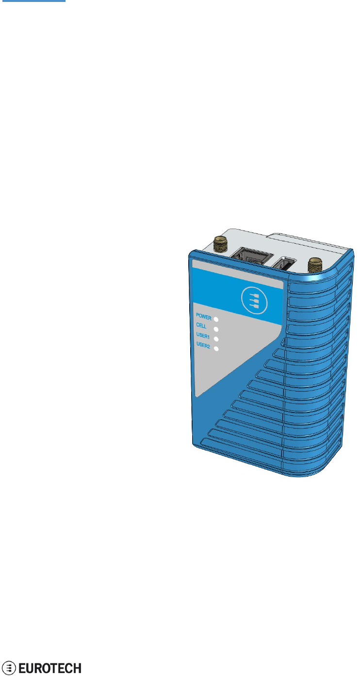
5 PRODUCT OVERVIEW
The ReliaGATE 10-05-34 is a compact and lightweight device intended to be used as Multi-Service IoT
Gateway. It is based on the NXP i.MX285 CPU, with 512MB of RAM, 4GB of eMMC, and a user-
accessible microSD slot.
It is suitable for intensive workload in industrial applications. It supports a 9 to 36 V power supply with
transient / surge / noise / reverse polarity protection, two protected serial ports (RS-232 and RS-485), and
one noise and surge protected USB port. An internal battery provides up to 30/50 minutes of uptime and
allows for a safe system shutdown in case of a blackout.
The ReliaGATE 10-05-34 can be equipped with Everyware™ Software Framework (ESF), a commercial,
enterprise-ready edition of Eclipse Kura, the open source Java/OSGi middleware for IoT gateways.
The ReliaGATE 10-05-34 can also take advance of Everyware Cloud (separately available). Everyware
Cloud (EC) is a specialized cloud solution that allows you to easily connect, configure and manage your
device through all its life-cycle.
A Development Kit is available upon request. It allows you to quickly and easily start the development of
your applications.
Figure 5.1 - The ReliaGATE 10-05-34
5 Product overview
ReliaGATE 10-05-34 User Manual Rev 1-0
16 / 62
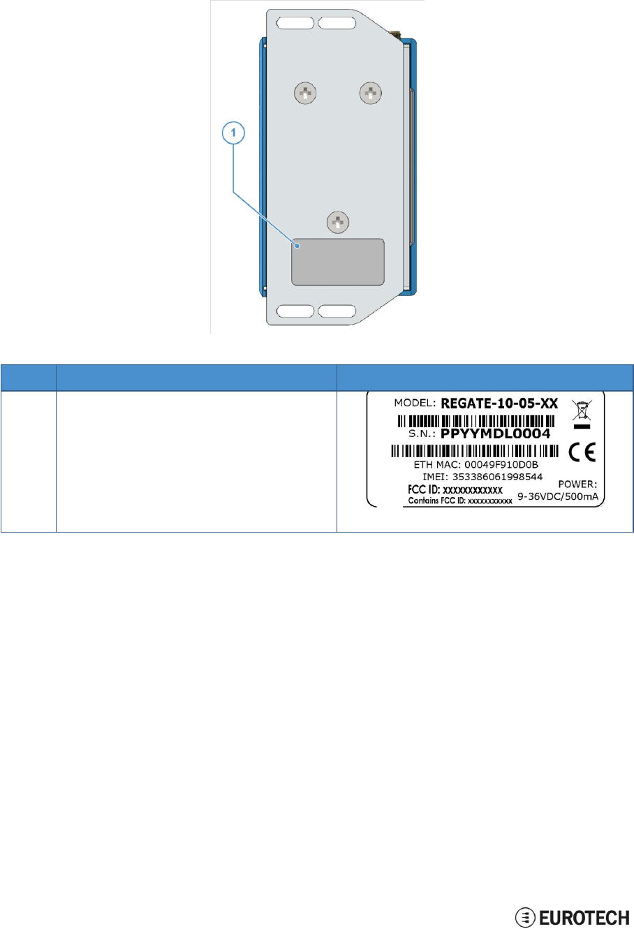
5.1 Product labels
The product label is placed on the bottom side of the product.
Ref#
Label content
Label exam
pl
e
1
• ReliaGATE model number
• ReliaGATE serial number
• WEEE symbol
• CE mark
• Ethernet MAC address
• IMEI number
• FCC ID numbers
• Power details

ReliaGATE 10-05-34 User Manual Rev 1-0
6 Declaration of Conformity
17 / 62
6 DECLARATION OF CONFORMITY
The ReliaGATE 10-05-34 conforms to the following:
l
Reduction of Certain Hazardous Substances (RoHS2)
l
CE Mark
l
Wi-Fi and Bluetooth Radio:
oCE - EN300 328 (2.4GHz ISM), EN50371 (EMI), EN301 489 (EMC)
oFCC - 15.209 (General RF device), 15.247 & 15.249 (2.4GHz ISM)
l
Cellular Radio:
oFCC PART 22, 24 & 27 and suitable GSM radio certifications
l
IEC/UL 60950-1 Information Technology Equipment - Safety - Part 1: General Requirements
l
Product compliance with part 15.21 of FCC
6.1 FCC Class A
no
t
i
ce
Conditions of operation
This product complies with Part 15 of the FCC Rules.
Operation is subject to the following two conditions:
1. This product may not cause harmful interference
2. This product must accept any interference received, including
interference that may cause undesired operation.
FCC Radio Frequency
Interference statement
This product has been tested and found to comply with the limits for a
Class A digital device, pursuant to Part 15 of the FCC Rules.
These limits are designed to provide reasonable protection against harmful
interference when the equipment is operated in a commercial environment.
This equipment generates, uses, and can radiate radio frequency energy,
and if it is not installed and used in accordance with the instruction manual,
Modifications
it may cause harmful interference to radio communications.
Operation of this equipment in a residential area is likely to cause harmful
interference, in which case the user will be required to correct the
interference at his own expense.
Any modifications made to this product that are not approved by Eurotech
may void the authority granted to the user by the FCC to operate this
product.
Product FCC IDs FCC ID: UKMMRG1005
Contains FCC ID: XPYLISAU201
STATEMENT:
1. This device complies with Part 15 of the FCC Rules. Operation is subject to the following two conditions:
(1)This device may not cause harmful interference.
(2)This device must accept any interference received, including interference that may cause undesired
operation.
2. Changes or modifications not expressly approved by the party responsible for compliance could void the
user's authority to operate the equipment.
Note: This equipment has been tested and found to comply with the limits for a Class A digital device,
pursuant to part 15 of the FCC Rules. These limits are designed to provide reasonable protection against
harmful interference when the equipment is operated in a commercial environment. This equipment
generates, uses, and can radiate radio frequency energy and, if not installed and used in accordance with the
instruction manual, may cause harmful interference to radio communications. Operation of this equipment in a
residential area is likely to cause harmful interference in which case the user will be required to correct the

6 Declaration of Conformity
ReliaGATE 10-05-34 User Manual Rev 1-0
18 / 62
interference at his own expense.
FCC Radiation Exposure Statement
This equipment complies with FCC radiation exposure limits set forth for an uncontrolled
environment. This equipment should be installed and operated with minimum distance of 20 cm
between the radiator and your body.
6.2 RoHS compliance
The product described in this document, including all its components and its sub-assemblies, have been
manufactured in compliance with the Directive 2011/65/EU of the European Parliament and of the Council
of 8 June 2011 on the restriction of the use of certain hazardous substances in electrical and electronic
equipment.
6.3 WEEE compliance

ReliaGATE 10-05-34 User Manual Rev 1-0
6 Declaration of Conformity
19 / 62
In compliance with the Directive 2012/19/EU of the European Parliament and of the Council
of 4 July 2012 on waste electrical and electronic equipment (WEEE), the symbol on the right,
shown on the product or within its literature, indicates separate collection for this electrical
and electronic equipment (EEE) that has been placed on the market after 2005.
This product, at the end of its life cycle, must be collected separately and managed in
accordance with the provisions of the current Directive on waste electrical and electronic
equipment.
Because of the substances present in the product, improper use or disposal of the refuse
can cause damage to human health and the environment.
To avoid any possible legal implications, contact your local waste collection body for full
recycling information.

(This page has been intentionally left blank)
20 / 62
7 TECHNICAL SPECIFICATIONS
Specifications
Description
Processor
CPU
NXP
i.MX285, 454MHz, 1 core
Memory
RAM
512 MB, DDR2
Storage
Embedded
4
GB
eMMC
Other
1x MicroSD slot (user accessible)
I/O Interfaces
Ethernet
1x Fast Ethernet port
USB
1x
USB
2.0 Host port (Noise and Surge Protected)
COM
1x RS-232 (3-wire, Surge Protected)
1x RS-485 (Surge Protected, with Termination and Fail-safe Resistors)
1x Console port (RS-232
Serial
port)
Radio interfaces
Cellular
3
G
global (integrated)
Wi-Fi / BT
802.11b,g,n / 4.0 BLE
Antennas (external)
1x SMA: Cellular
1x RP-SMA:
W
i-
F
i / Bluetooth
Other
RTC
Yes
External Watchdog
Yes
UPS
Integrated Li-ion
Battery
(3.7V, 48mAh), Safe shutdown and Power state restore
LEDs
1x Power
1x Cellular activity
2x User configurable
Buttons
1x Reset, 1x Programmable
SIM slot
1x MicroSIM (user accessible)
Power
Input
Nominal: 24 V dc; Range: 9 - 36 V dc with Transient, Surge, Noise, Reverse
Polarity, Overvoltage protection
Consumption
1.5 W idle
Environment
Operating Temp
0 °C to +50 °C
Storage Temp
-40 °C to +85 °C
Certifications
Regulatory
CE, FCC
Safety
IEC/UL 60950-1
Environmental
RoHS2; REACH
Radio
CE - EN 300 328 (2.4
G
Hz ISM), EN 50371 (EMI), EN 301489 (EMC)
FCC - 15.209
(General
RF device), 15.247 & 5.249 (2.4
G
Hz ISM)
Cellular
PTCRB
FCC PART 22, 24 & 27 and suitable GSM radio certifications
Ingress
IP40
Mechanical
Enclosure
Material:
ABS
(Color: blue) and Aluminum
Dimensions
112 (L) x 68 (W) x 37 (H); mm
Weight
180 g (Mounting Bracket included)
Mounting
Mounting Bracket (Optional: DIN Rail Mounting Kit)

ReliaGATE 10-05-x4 User Manual Rev 1-0
8 Getting started
21 / 62

ReliaGATE 10-05-34 User Manual Rev 1-0
8 Getting started
21 / 62
8 GETTING STARTED
Follow these steps to get started with your ReliaGATE 10-05-34
:
1. Know the ReliaGATE 10-05-34 interfaces.
The ReliaGATE 10-05-34 provides connectivity to several wired and wireless interfaces.
For further information, see:
l
"Product interfaces" on page 23
l
"Interfaces in detail" on page 27
2. Apply power to the ReliaGATE 10-05-34.
The ReliaGATE 10-05-34 supports a variety of usage scenarios.
For further information, see "Power supply" on page 27
3. Log into the Administration console.
The ReliaGATE 10-05-34 runs a Linux distribution based on a Yocto framework and supports login
via a variety of methods.
For further information, see:
l
"The Software" on page 39
l
"How to log in the Administration Console" on page 49
l
"How to access the interfaces under Linux" on page 41
4. Install the ReliaGATE 10-05-34.
The ReliaGATE 10-05-34 is lightweight and compact. You can easily install it, even on a DIN rail.
For further information, see:
l
"Mechanical specifications" on page 53
l
"How to install the product" on page 55
5. Start developing your applications.
Your ReliaGATE 10-05-34 supports ESF, which is an inclusive software framework that puts a
middleware layer between the operating system and the OEM application.
For detailed instructions, and sample applications for developing device applications using ESF on
Eurotech platforms, see: http://esf.eurotech.com/docs.
(This page has been intentionally left blank)
ReliaGATE 10-05-34 User Manual Rev 1-0
9 Product interfaces
23 / 62
9 PRODUCT INTERFACES
This section gives you an overview of the interfaces available on the ReliaGATE 10-05-34.
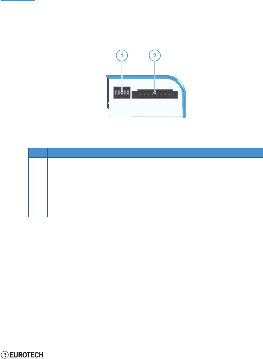
9.1 Front panel interfaces
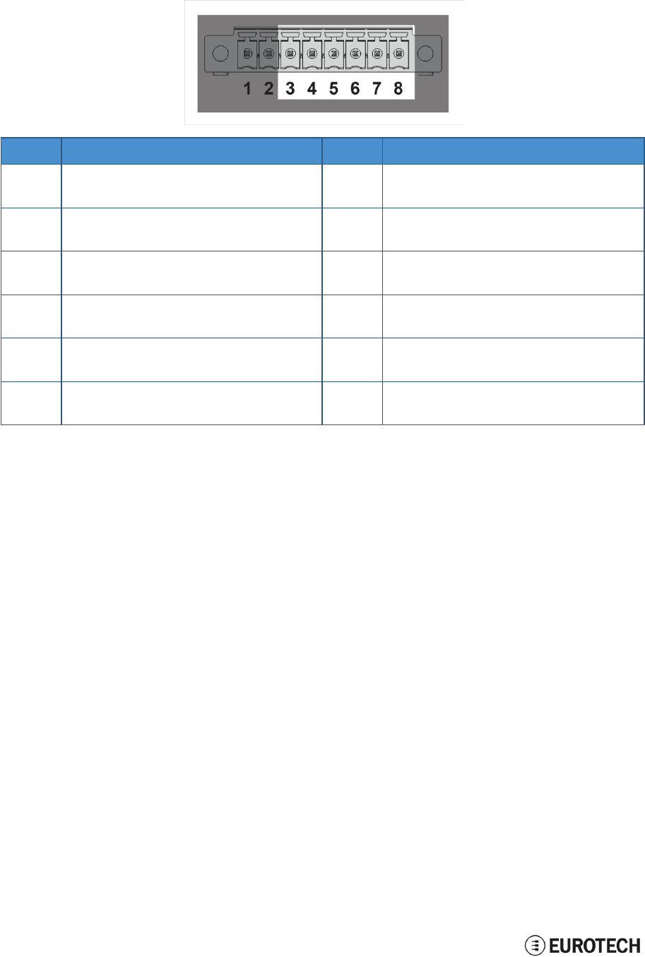
The interfaces available on the front panel are the following:
Figure 9.1 - Front panel interfaces layout
Ref#
Description
Connector / Mating connector information
1
DIP switch selector
-
2
8-position connector
Connector: Base strip, Header;
8-pin, 3.5 mm pitch
Mating connector: Pluggable screw terminal block;
8-pin, 3.5 mm pitch
Example:
• Shenzhen Connection Electronics Co., Ltd.
• P/N: PLTB1.5-08-BF-3.50-GY
Table 9.1 - Rear panel interfaces description
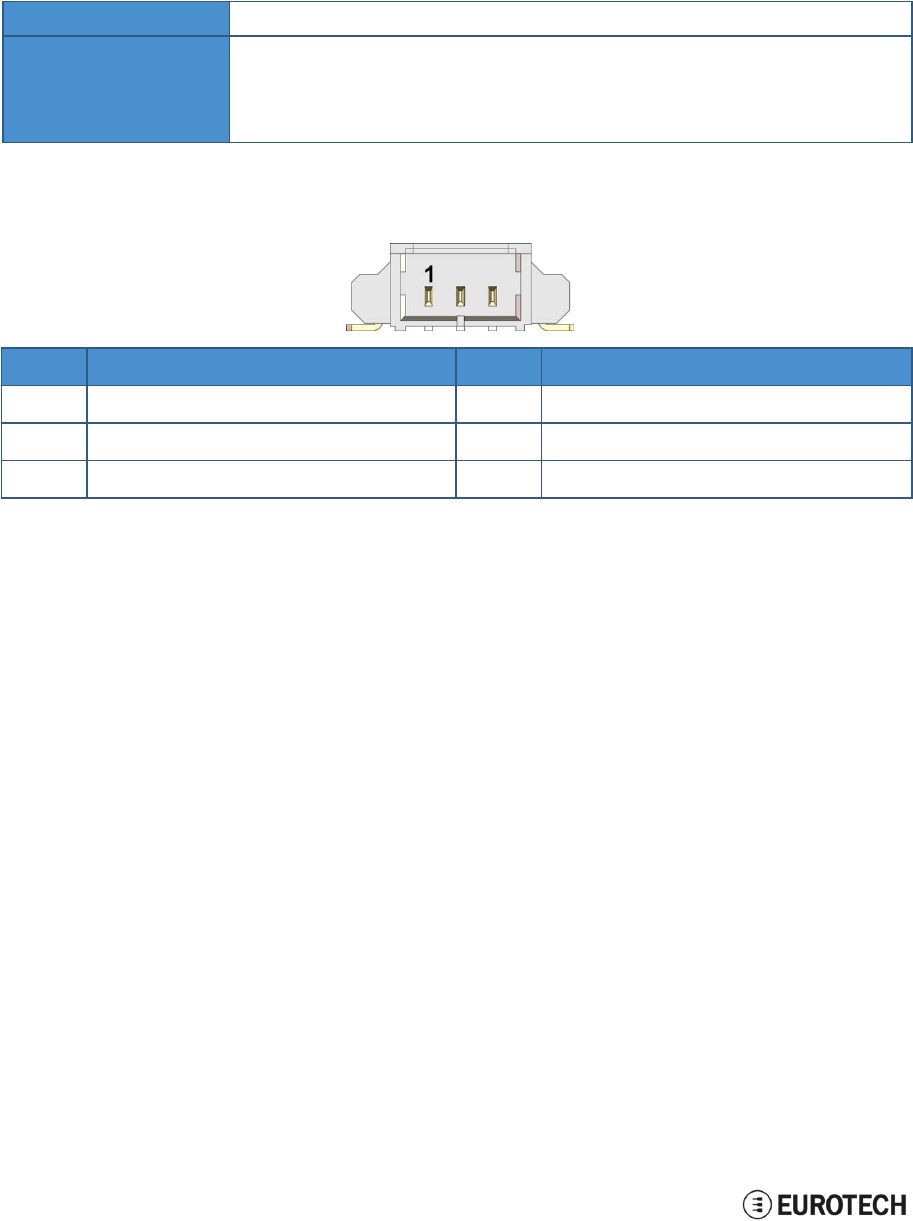
9.1.1 DIP switch selector functions
Use the DIP switch selector
t
o
:
l
Insert the RS-485 fail-safe resistors
l
Insert the RS-485 termination resistors
l
Control the Boot sequence
l
Enable the watchdog
9.1.2 8-position connector functions
Use the 8-position connector
t
o
:
l
Connect the power input
l
Connect the RS-485 Serial port
l
Connect the RS-232 Serial port
9 Product interfaces
ReliaGATE 10-05-34 User Manual Rev 1-0
24 / 62
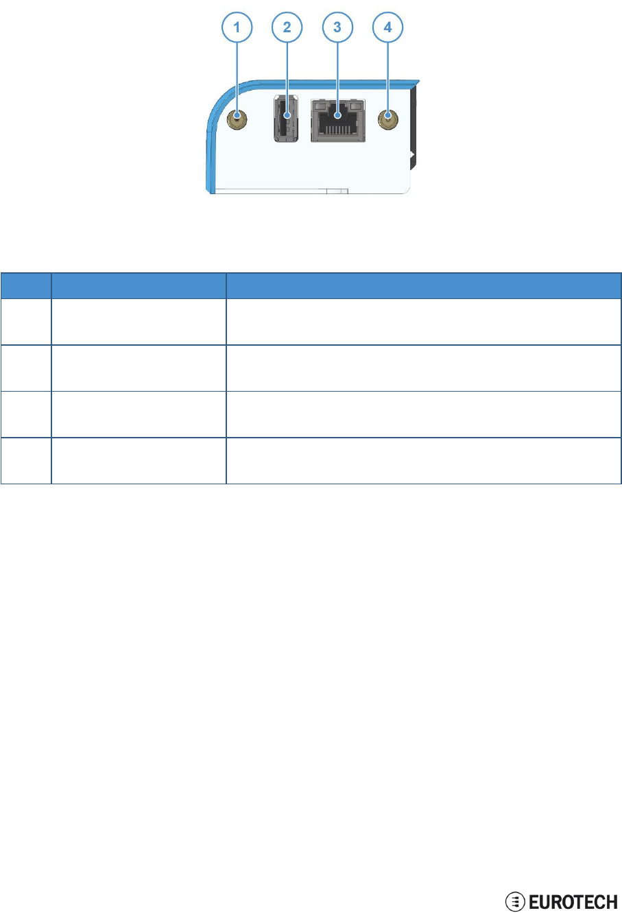
9.2 Rear panel interfaces
The interfaces available on the rear panel are the following:
Figure 9.2 - Rear panel interfaces layout
Ref#
Description
Connector / Mating connector information
1
Cellular antenna connector
Connector: Female SMA
Mating connector: Male SMA
2
USB 0 host port
Connector: USB Type-A socket
Mating connector: USB Type-A plug
3
Ethernet 0 port
Connector: Female RJ-45
Mating connector: Male RJ-45
4
Wi-Fi/BT antenna connector
Connector: Female RP-SMA
Mating connector: Male RP-SMA
Table 9.2 - Rear panel interfaces description
ReliaGATE 10-05-34 User Manual Rev 1-0
9 Product interfaces
25 / 62
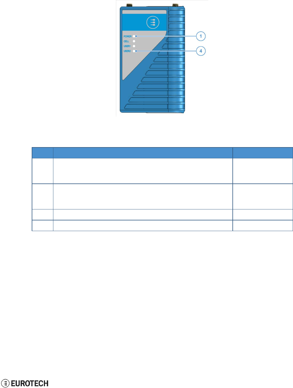
9.3 LED indicators
The available LED indicators are the following:
Figure 9.3 - LED indicators layout
Ref#
Use
Color
1
POWER:
- LED ON: ReliaGATE powered by the external source
- LED OFF: ReliaGATE not powered by the external source
Blue
2
CELL (Cellular modem activity):
- LED ON means modem ON;
- LED blinking means modem attached to GSM network
Green
3
USER1 (General purpose)
Green / Amber
4
USER2 (General purpose)
Green / Amber
Table 9.3 - LED indicators description
To manage the USER LEDs see "LED indicators" on page 42.
9 Product interfaces
ReliaGATE 10-05-34 User Manual Rev 1-0
26 / 62
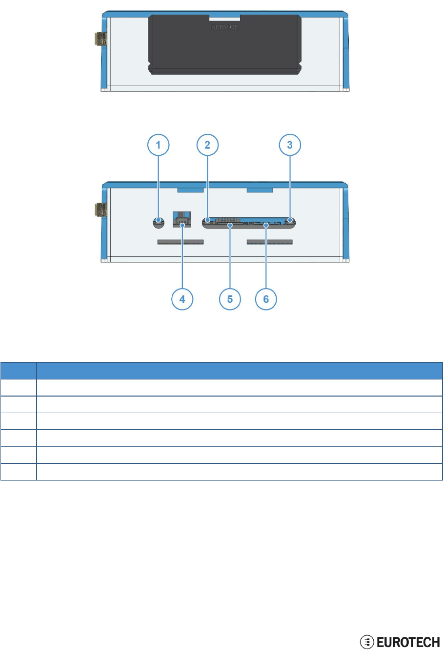
9.4 Service panel interfaces
The interfaces available behind the service panel are the following:
Figure 9.4 - Service panel interfaces layout
Ref#
Description
1
Reset pushbutton
2
Programmable pushbutton
3
TBD
4
Console port
5
Micro SD card slot
6
Micro SIM card slot
Table 9.4 - Service panel interfaces description
ReliaGATE 10-05-34 User Manual Rev 1-0
10 Interfaces in detail
27 / 62
10 INTERFACES IN DETAIL
10.1 Power supply
10.1.1 Power supply parameters
Power supply
Nominal: 24 V dc; Range: 9 - 36 V dc with Transient, Surge, Noise, Reverse
Polarity, Overvoltage protection
Power consumption
1.5 W idle
Peak demand
< 15 W
The power input is protected against: surge, noise, reverse polarity, over-voltage and short circuit.
The power input is also protected with a resettable fuse.
10.1.2 Power supply connector pinout
The power supply input is available on the 8-position connector located on the front panel, pins 1 and 2.
Pin#
Name
Type
Description
1
Power IN +
P
Positive power supply input
2
Power IN -
P
Negative power supply input
10.1.3 How to turn ON the ReliaGATE 10-05-34
To turn the ReliaGATE 10-05-34 ON, supply power to Pins 1 and 2.
The system automatically turns ON and the LED 1
(POWER)
turns ON.
10.1.4 How to turn OFF the ReliaGATE 10-05-34
To turn the ReliaGATE 10-05-34 OFF, follow these steps:
1. Login the Administration console and run the shutdown command. The system turns OFF
2. Remove power from pins 1 and 2.
10.1.5 How to manage the ReliaGATE 10-05-34 power consumption
To reduce the power consumption of your ReliaGATE 10-05-x4: turn OFF the radio interfaces and / or set
the CPU in low power consumption mode (sleep mode).
The maximum power consumption at the lowest power state is ≤ 0.4 W.
To wake the ReliaGATE 10-05-34 up from the low power consumption mode, use the Console port.
10 Interfaces in detail
ReliaGATE 10-05-34 User Manual Rev 1-0
28 / 62
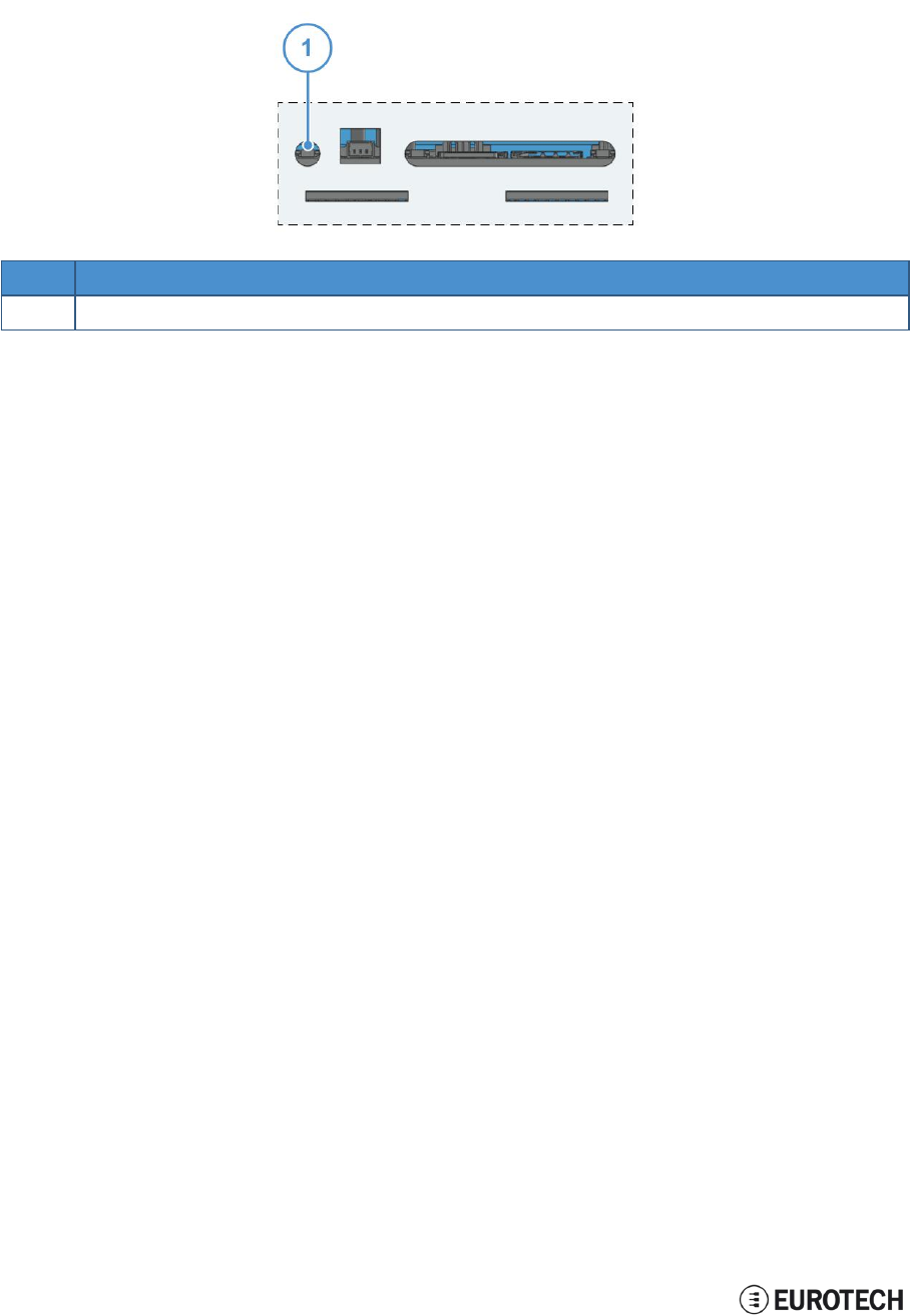
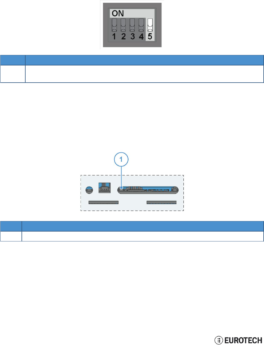
10.1.6 How to perform a power reset of the ReliaGATE 10-05-34
To trigger a hardware reset of the ReliaGATE 10-05-34, push the reset pushbutton available behind the
Service Panel.
Ref#
Description
1
Reset pushbutton
ReliaGATE 10-05-34 User Manual Rev 1-0
10 Interfaces in detail
29 / 62
10.2 Wi-Fi and Bluetooth
The ReliaGATE 10-05-34 includes a WLAN + Bluetooth (BT) module and an external antenna connection
to fully implement 802.11b,g,n WiFi and Bluetooth 4.0 functions.
10.2.1 Wi-Fi specifications
Specification
Description
Standard
IEEE 802.11b, g, n, Wi-Fi compliant
Frequency Range
2.400 GHz to 2.497 GHz (2.4 GHz ISM Band)
Number of Channels
2.4GHz:Ch1 to Ch14
Modulation
802.11b : DQPSK, DBPSK, CCK
802.11g, n: OFDM /64-QAM,16-QAM, QPSK, BPSK
Data Rate
802.11b: 1, 2, 5.5, 11 Mbps
802.11g: 6, 9, 12, 18, 24, 36, 48, 54 Mbps
Data Rate
(20 MHz, Long GI, 800 ns)
802.11n: 6.5, 13, 19.5, 26, 39, 52, 58.5, 65 Mbps
Data Rate
(20 MHz, Short GI, 400 ns)
802.11n: 7.2, 14.4, 21.7, 28.9, 43.3, 57.8, 65,72.2Mbps
Maximum Input Level
802.11b: -10 dBm
802.11g, n: -20 dBm
Antenna Reference
Small antennas with 0 to 2 dBi peak gain
10.2.2 Bluetooth specifications
Specification
Description
Standard
Bluetooth V4.0 of 1, 2 and 3 Mbps
Host Interface
UART
Antenna Reference
Small antennas with 0 to 2 dBi peak gain
Frequency Band
2402 MHz to 2480 MHz
Number of Channels
79
Modulation
FHSS, GFSK, DPSK, DQPSK
10 Interfaces in detail
ReliaGATE 10-05-34 User Manual Rev 1-0
30 / 62
10.3 Cellular
The ReliaGATE 10-05-34 integrates a cellular modem having the following characteristics:
Specification
Description
UMTS/HSPA
800/850/900/1900/2100 MHz (Bands VI, V, VIII, II, I)
3GPP Release 7
5.76 Mb/s uplink, 21.1 Mb/s downlink
or 5.76 Mb/s uplink, 7.2 Mb/s downlink
GSM
GSM 850 / 900 / 1800 / 1900 MHz
3GPP Release 7, PBCCH support
GPRS
Class 12, CS1-CS4 - up to 86.5 kb/s
EDGE
Class 12, MCS1-9 - up to 236.8 kb/s
CSD
GSM max 9.6 kb/s
UMTS
Max 64 kb/s
SMS
MT/MO PDU / Text mode
Protocols
Embedded TCP/IP, UDP/IP
HTTP/FTP/SSL
(Secure Socket Layer)
Network
Jamming detection
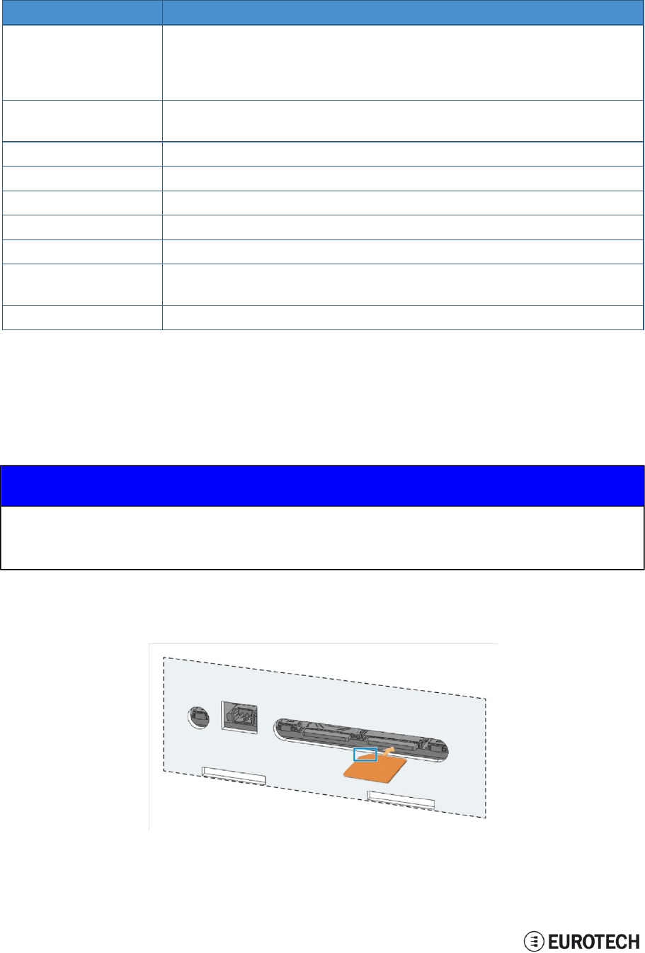
10.4 The MicroSIM card receptacle
Your ReliaGATE 10-05-34 includes a push-push type Micro SIM card receptacle.
This interface is available behind the Service Panel.
NOTICE
TURN THE SIM PIN OFF!
Turn the SIM PIN OFF before inserting the SIM card in the receptacle!
The cellular connection will not work if the SIM PIN is ON!
Insert the MicroSIM card as in the picture below, with the contacts facing down, and the cut corner facing
inwards.
ReliaGATE 10-05-34 User Manual Rev 1-0
10 Interfaces in detail
31 / 62
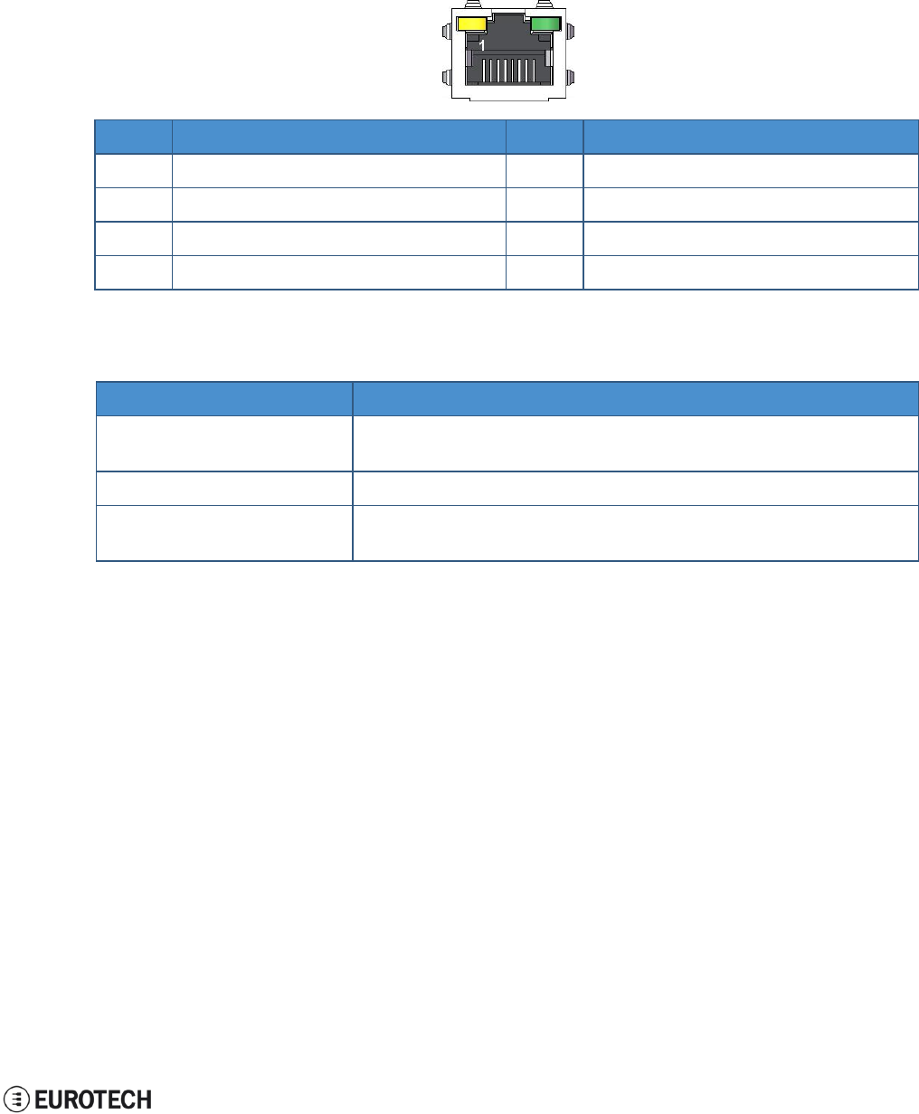
10.5 Ethernet port
On the rear panel, the ReliaGATE 10-05-34 provides one 10/100 Mbps Ethernet port for wired network
connectivity: ETH0.
10.5.1 Connector pinout
Pin#
Name
Type
Description
1
TX+
O
Transmit Data +
2
TX-
O
Transmit Data -
3
RX+
I
Receive Data +
6
RX-
I
Receive Data -
10.5.2 Port specifications
Feature
Description
Network Standard
IEEE802.3u 10/100-BaseTX.
IEEE 802.3x full-duplex flow control.
Speeds
10/100-BaseTX interfaces with MAC
Notes
The interfaces are noise and surge protected.
The RJ-45 connector has integrated magnetics.
10 Interfaces in detail
ReliaGATE 10-05-34 User Manual Rev 1-0
32 / 62
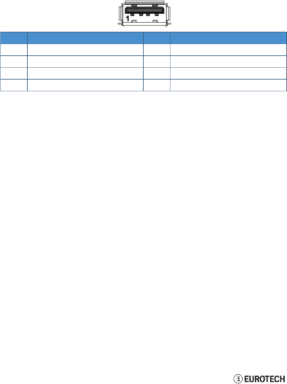
10.6 Host USB port
The ReliaGATE 10-05-34 provides one USB 2.0 host port For power supply only”.
This interface is available on the rear panel, and is noise and surge protected.
10.6.1 Connector pinout
Pin#
Name
Type
Description
1
VBUS
5
+5V
2
D-
IO
Negative data
3
D+
IO
Positive data
4
DGND
P
Digital ground
ReliaGATE 10-05-34 User Manual Rev 1-0
10 Interfaces in detail
33 / 62
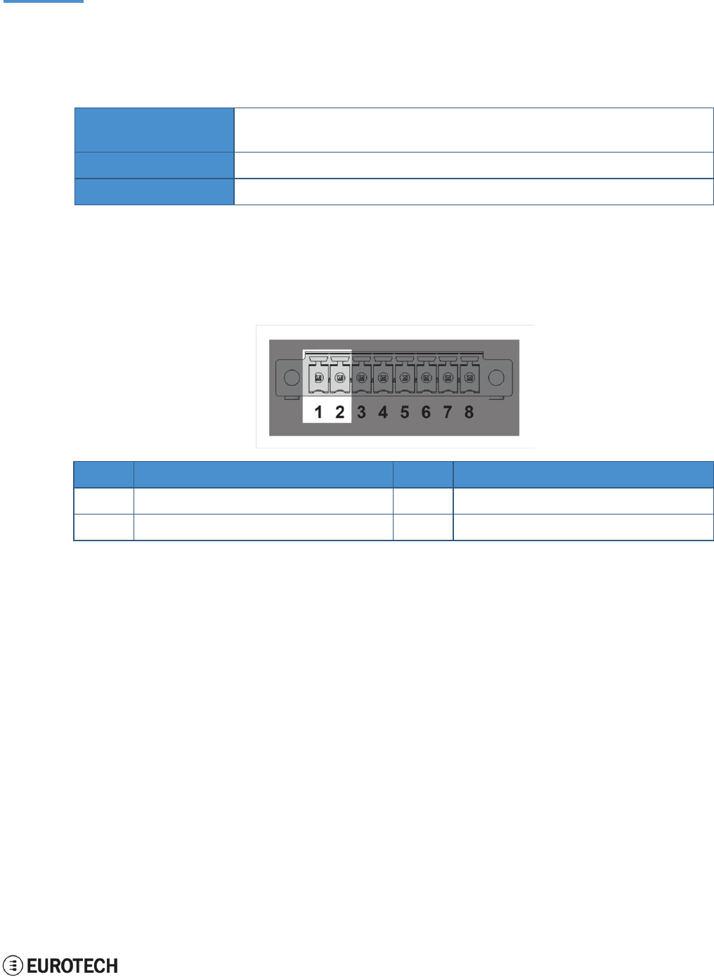
10.7 COM ports 0 and 1
The ReliaGATE 10-05-34 provides 2 COM ports on the 8-position connector located on the front panel (pins
3 to 8):
Port
Type
Protection
Max baud rate
COM 0
RS-485
Surge Protected
Up to 3.6864 Mbps
COM 1
RS-232 (3-wire)
Surge Protected
Up to 450 kbps
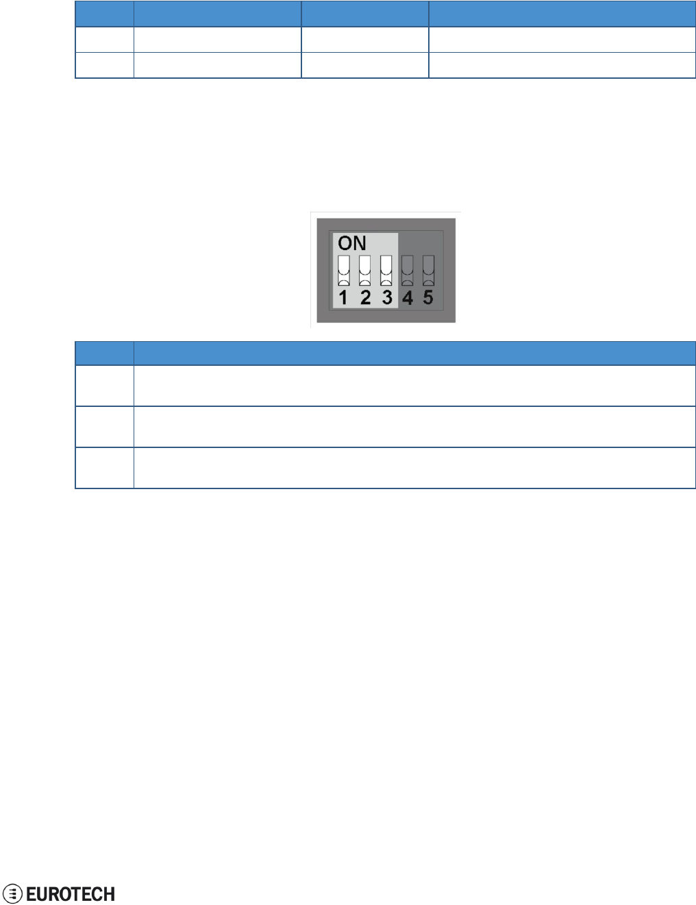
10.7.1 How to insert RS-485 fail-safe and termination resistors
To insert the RS-485 fail-safe and termination resistors use the DIP switch selector located on the front
panel, sliding levers 1 to 3.
The sliding levers have the following meaning:
Lever #
Description
1
ON: 4.7 kΩ pull-up resistor inserted on line RS-485+ (A)
OFF: No resistor inserted (default configuration)
2
ON: 4.7 kΩ pull-down resistor inserted on line RS-485- (B)
OFF: No resistor inserted (default configuration)
3
ON: 120 Ω termination resistor inserted on lines RS485+ / RS485- (A / B)
OFF: No resistor inserted (default configuration)
10 Interfaces in detail
ReliaGATE 10-05-34 User Manual Rev 1-0
34 / 62
10.7.2 COM ports pinout
The 2 COM ports are available on the 8-position connector located on the front panel, pins 3 to 8.
Pin#
Name
Type
Description
3
COM 0: RS-485+ (A)
I/O
COM port 0 (RS-485):
l
A Line
4
COM 0: RS-485- (B)
I/O
COM port 0 (RS-485):
l
B Line
5
COM 0: GND
P
COM port 0 (RS-485):
l
Ground
6
COM 1: TX
O
COM port 1 (RS-232):
l
Transmit Data
7
COM 1: RX
I
COM port 1 (RS-232):
l
Receive Data
8
COM 1: GND
P
COM port 1 (RS-232):
l
Ground
ReliaGATE
10-05-34
User Manual Rev 1-0
10 Interfaces
in detail
10.8 The MicroSD card
receptacle
The ReliaGATE 10-05-34 includes a push-push type Micro SD card receptacle behind the Service Panel.
Insert the Micro SD card as in the picture below, with the contacts facing down.
,.
_
·-----
------------- -
@EUROTECH 35 /62
10 Interfaces in detail
ReliaGATE 10-05-34 User Manual Rev 1-0
36 / 62
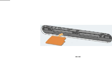
10.9 Console port
The ReliaGATE 10-05-34 provides a Console port behind the Service Panel.
It is an RS-232 serial port. You can use it to access the Operating System.
10.9.1 Connector and mating connector specifications
Connector
Shrouded header, 3-pin, 1.25 mm pitch
Mating connector
Receptacle Housing, 3-pin, 1.25 mm pitch
Example:
l
Manufacturer: Molex
l
Part number: 51021-0300
10.9.2 Connector pinout
Pin#
Name
Type
Description
1
TX
O
Transmit Data
2
RX
I
Receive Data
3
DGND
P
Digital Ground

ReliaGATE 10-05-34 User Manual Rev 1-0
10 Interfaces in detail
37 / 62
10.10 RTC (Real Time Clock)
Your ReliaGATE 10-05-34 includes the following two RTC (Real Time Clocks) devices:
RTC device
Description
Use
/dev/rtc0
l
It comes from the CPU SoC
Reserved
/dev/rtc1
l
It does not come from the CPU SoC
l
It is the default RTC used by Linux to set and get
the Wall time while booting up and while
suspending / resuming
l
It has an accuracy of 25 minutes per year (at 25 °C)
l
It can trigger an interrupt to the CPU.
Wake your ReliaGATE 10-
05-x4 up from a deep low
power state
10.10.1 The RTC device "/dev/rtc1"
The RTC device "/dev/rtc1" o
ff
ers
:
l
three timestamp regis
t
ers
l
one user-available by
t
e
To manage the RTC device see the section "RTC" on page 44.
10 Interfaces in detail
ReliaGATE 10-05-34 User Manual Rev 1-0
38 / 62
10.11 Watchdog
Your ReliaGATE 10-05-34 includes a watchdog / supervisor IC, external to the CPU.
To manage the watchdog see the section "Watchdog" on page 46.
10.11.1 How to enable / disable the watchdog
To enable / disable the watchdog use the DIP switch selector located on the front panel, sliding lever 5.
The sliding lever has the following meaning:
Lever #
Description
5
ON: Watchdog disabled
OFF: Watchdog enabled (default configuration)
10.12 The Programmable pushbutton
A programmable pushbutton is available behind the Service Panel.
The pushbutton is sensed by a Linux daemon which executes a shell script every time the button is either
pushed or released.
Ref#
Description
1
Programmable pushbutton
ReliaGATE 10-05-34 User Manual Rev 1-0
11 The Software
39 / 62
11 THE SOFTWARE
11.1 The Linux OS distribution
Eurotech can provide a Linux operating systems based on Yocto framework (www.yoctoproject.org) as
well as an SDK for application development.
All the documentation for the developer is available from: www.yoctoproject.org/documentation.
11.2 The bootloader procedure
The bootloader procedure is the following:
1. The MLO file is loaded from the on-board eMMC memory, and saved in the on-chip memory to
configure the RAM memory for use
2. The u-boot.img file is loaded, saved in the RAM memory, and executed
3. U-Boot executes the Linux kernel from either one of the following sources:
l
From the Ethernet from a server with a defined IP address
l
From the on-board eMMC
4. U-Boot fetches the Linux kernel (/boot/zImage) and the device tree (/boot/reliagate-10-11.dtb), and
boots the operating system up
11.2.1 How to select the Linux kernel sources
U-boot can execute the Linux kernel from either one of the following sources:
l
From the Ethernet from a server with a defined IP address
l
From the on-board eMMC
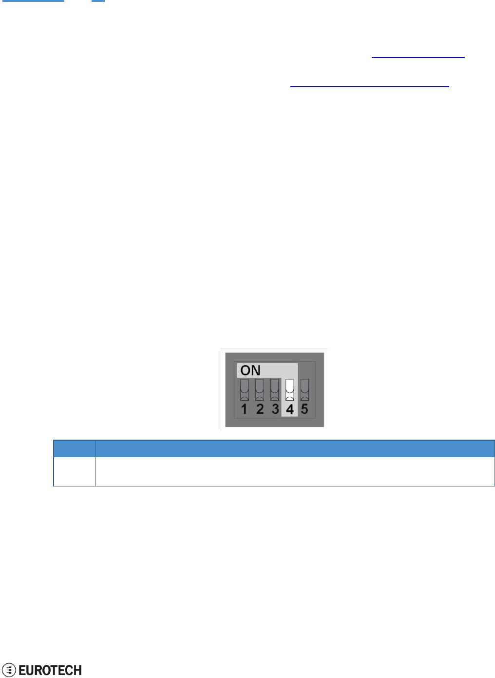
To select the Linux kernel source use the DIP switch selector located on the front panel, sliding lever 4.
The sliding lever has the following meaning:
Lever #
Description
4
ON: U-boot executes the Linux kernel from the Ethernet
OFF: U-boot executes the Linux kernel from the on-board eMMC (default configuration)
11.2.2 How to set up a correct eMMC card partition
To allow the correct bootloader procedure, configure the eMMC memory with at least these 2 partitions:
l
1st partition:
oType: FAT16
oFlags: lba, boot
oContains the files: MLO and u-boot.img
l
2nd partition:
oType: ext4
oContains the operating system, including the Linux kernel (/boot/zImage) and the device tree
(/boot/reliagate-10-11.dtb)
(This page has been intentionally left blank)
ReliaGATE 10-05-34 User Manual Rev 1-0
12 How to access the interfaces under Linux
41 / 62
l
COM port 0:
/dev/ttyO4 (
l
COM port 1:
/dev/ttyO3 (
l
Console port
/dev/ttyO0 (
12 HOW TO ACCESS THE INTERFACES UNDER LINUX
12.1 Ethernet port
On the rear panel, the ReliaGATE 10-05-x4 exposes one 10/100 Mbps Ethernet port for wired network
connectivity:
l
Ethernet 0 port, referenced as eth0
12.2 Wi-Fi and Bluetooth
On the rear panel, the ReliaGATE 10-05-x4 exposes an external antenna connection to fully implement Wi-
Fi 802.11b/g/n and Bluetooth 4.0 BLE functions:
l
The Wi-Fi interface is referenced as wlan0
l
The Bluetooth interface is referenced as hci0
12.3 Modem
By default the ReliaGATE 10-05-x4 exposes the modem as follows:
l
AT commands port (data communication): /dev/ttyACM0
To turn the modem OFF unconditionally, use the following commands:
echo
1 >
/
s
y
s
/
c
l
a
ss
/
gp
i
o
/
gp
i
o30
/
v
a
l
u
e
s
l
ee
p 0
.
5
echo
0 >
/
s
y
s
/
c
l
a
ss
/
gp
i
o
/
gp
i
o30
/
v
a
l
u
e
To toggle the modem power status, use the following commands:
echo
1 >
/
s
y
s
/
c
l
a
ss
/
gp
i
o
/
gp
i
o60
/
v
a
l
u
e
s
l
ee
p 5
echo
0 >
/
s
y
s
/
c
l
a
ss
/
gp
i
o
/
gp
i
o60
/
v
a
l
u
e
12.4 COM ports 0 and 1, Console port
The ReliaGATE 10-05-x4 exposes the COM ports as follows:
available on the front panel)
available on the front panel)
available behind the service panel)
12.4.1 How to test a COM port
Use the utility below to test the COM port. It works in either RS-232 or RS-485 mode.
This utility allows you to transmit/receive data to/from the COM port.
NOTE: this utility does not include a local echo (it does not allow you to see the sent data)
#
c
onn
ec
t tt
y
O
3
w
it
h
a baud
r
a
t
e
of
9600
m
i
c
r
o
c
o
m
/
d
e
v
/tt
y
O
3
–s
9600
12 How to access the interfaces under Linux
ReliaGATE 10-05-34 User Manual Rev 1-0
42 / 62
12.5 LED indicators
The available LED indicators are the following:
Ref#
Use
Color
1
POWER:
- LED ON: ReliaGATE powered by the external source
- LED OFF: ReliaGATE not powered by the external source
Blue
2
CELL (Cellular modem activity):
- LED ON means modem ON;
- LED blinking means modem attached to GSM network
Green
3
USER1 (General purpose)
Green / Amber
4
USER2 (General purpose)
Green / Amber
They are exposed as follows:
l
LED 1:
Reserved
l
LED 2:
/sys/class/gpio/gpio114/value
l
LED 3:
/sys/class/gpio/gpio115/value
l
LED 4:
/sys/class/gpio/gpio116/value
12.5.1 How to manage a LED
Each LED is managed by its respective GPIO.
Each GPIO needs to be exported before you can use it.
The export procedure has to be repeated at each power ON.
To drive a LED, complete the following steps:
1. Export the LED (if it hasn’t already exported before)
2. Drive the LED
To export LED3, use the following commands:
#
e
xpo
r
t
gp
i
o 117
echo
117 >
/
s
y
s
/
c
l
a
ss
/
gp
i
o
/
e
xpo
r
t
#gp
i
o
is
ou
t
pu
t
echo
ou
t
>
/
s
y
s
/
c
l
a
ss
/
gp
i
o117
/
d
i
r
ec
ti
on
To drive LED3, use the following commands:
#
t
u
r
n
l
e
d on
echo
1 >
/
s
y
s
/
c
l
a
ss
/
gp
i
o117
/
v
a
l
u
e
#
t
u
r
n
l
e
d o
ff
echo
0 >
/
s
y
s
/
c
l
a
ss
/
gp
i
o117
/
v
a
l
u
e

ReliaGATE 10-05-34 User Manual Rev 1-0
12 How to access the interfaces under Linux
43 / 62
12.6 Flash Memory
The ReliaGATE 10-05-x4 exposes the flash memory as follows:
l
Internal flash (eMMC) memory:
/dev/mmcblk0
l
MicroSD card memory:
/dev/mmcblk1
12 How to access the interfaces under Linux
ReliaGATE 10-05-34 User Manual Rev 1-0
44 / 62
12.7 RTC
The ReliaGATE 10-05-x4 exposes the user-available RTC as follows:
l
RTC: /dev/rtc1
The "/dev/rtc1" offers:
l
three timestamp registers
l
one user-available byte.
12.7.1 How to manage the timestamp registers
The timestamp registers are the following:
Timestamp register
What it contains
sys/class/rtc/rtc1/device/timestamp1
Reserved data
sys/class/rtc/rtc1/device/timestamp2
The timestamp that the system last lost power (only if a
successful initialization has been achieved)
sys/class/rtc/rtc1/device/timestamp3
The timestamp that the system last has been powered
(only if a successful initialization has been achieved)
You can only read and reset the timestamp registers.
To read the timestamp2, use the following command:
ca
t /
s
y
s
/
c
l
a
ss
/
r
t
c
/
r
t
c
1
/
d
e
v
i
ce
/ti
m
e
s
t
a
m
p2
To reset the timestamp2, use the following command:
echo
ti
m
e
s
t
a
m
p2
>
/
s
y
s
/
c
l
a
ss
/
r
t
c
/
r
t
c
1
/
d
e
v
i
ce
/
r
e
s
e
t
s
12.7.2 How to manage the user-available
b
yte
The user-available byte is the
f
ollowing
:
User-available byte
What it contains
/sys/class/rtc/rtc1/device/ram_byte
The default value is 0.
You can write in it a value included in the range: 0 to 255.This
value is retained as long as the /dev/rtc1 device receives a
valid power supply (main power supply or battery)
You can read and write the user-available byte.
To read the byte, use the following command:
ca
t /
s
y
s
/
c
l
a
ss
/
r
t
c
/
r
t
c
1
/
d
e
v
i
ce
/
r
a
m
_by
t
e
To write 112 in the byte, use the following command:
echo
112 >
/
s
y
s
/
c
l
a
ss
/
r
t
c
/
r
t
c
1
/
d
e
v
i
ce
/
r
a
m
_by
t
e
ReliaGATE 10-05-34 User Manual Rev 1-0
12 How to access the interfaces under Linux
45 / 62
12.7.3 How to manage the sleep mode (example)
To make the ReliaGATE 10-05-34 enter sleep mode, use the following command:
echo
m
e
m
>
/
s
y
s
/
po
w
e
r
/
s
t
a
t
e
The commands in the example below perform the following actions:
1. Sets a specific date and time in the ReliaGATE 10-05-34: 4 September 2015 at 10:00 AM
2. Tells the ReliaGATE 10-05-34 to automatically wake up 20 seconds after the specific date and time
3. Makes the ReliaGATE 10-05-34 enter sleep mode
#
s
e
t
c
u
rr
e
n
t
d
a
t
e
and
ti
m
e
DA
TE
=
”
09
/
04
/
2015
”
T
I
M
E
=
”
10
:
00
:
00
”
d
a
t
e
+
”
%
m
/
%
d
/
%
y
%
H
:
%
M
:
%
s
” –s “
$
DA
TE
$
T
I
M
E
”
#
s
e
t
w
a
k
e
up
d
a
t
e
and
ti
m
e
r
t
c
t
e
s
t
–d
/
d
e
v
/
r
t
c
1
–a
“
04
/
09
/
2015 10
:
00
:
20
”
#
e
n
t
e
r
s
l
ee
p
m
od
e
echo
m
e
m
>
/
s
y
s
/
po
w
e
r
/
s
t
a
t
e
To make the ReliaGATE 10-05-34 exit from sleep mode, use the following procedure:
1. Connect the Console port
2. Send a character on the Console port
12 How to access the interfaces under Linux
ReliaGATE 10-05-34 User Manual Rev 1-0
46 / 62
12.8 Watchdog
The ReliaGATE 10-05-34 exposes the watchdog as follows:
l
Watchdog: /dev/watchdog1
12.8.1 How to manage the watchdog using the C programming language
To manage the watchdog using the C programming language use the following commands:
I
n
t i
n
t
e
r
v
a
l;
I
n
t
boo
t
s
t
a
t
u
s
;
Long
v
a
l
u
e
;
/
* d
i
s
p
l
a
y
c
u
rr
e
n
t
w
a
t
c
hdog v
a
l
u
e
*
/
If (
i
o
c
tl
(f
d
,
W
D
I
O
C
_
G
ETT
I
M
E
OU
T
,
&
i
n
t
e
r
v
a
l
)
==
0
)
{
// i
n
t
e
r
v
a
l
c
on
t
a
i
n
s
c
u
rr
e
n
t ti
m
e
ou
t i
n
s
ec
ond
s
}
/
*
C
h
ec
k
if
l
a
s
d
t
boo
t
is
caused
by
w
a
t
c
hdog *
/
If (
i
o
c
tl
(f
d
,
W
D
I
O
C
_
G
ET
B
OO
T
S
T
A
T
U
S
,
&
boo
t
s
t
a
t
u
s
)
==
0
)
{
//
boo
t
s
t
a
t
u
s
<> 0
W
a
t
c
hdog
//
boo
t
s
t
a
t
u
s
= 0
P
o
w
e
r-
on
r
e
s
e
t
}
/
*
s
e
t t
h
e
w
a
t
c
hdog v
a
l
u
e
(f
o
r
e
x
a
m
p
l
e
:
30
s
ec
ond
s
)
*
/
v
a
l
u
e
=
30
;
If (
i
o
c
tl
(f
d
,
W
D
I
O
C
_
S
ETT
I
M
E
OU
T
,
&
v
a
l
u
e
)
==
0
)
{
//
W
a
t
c
hdog
has been
s
e
t t
o v
a
l
u
e c
on
t
e
n
t
}
/
*
s
t
op
t
h
e
w
a
t
c
hdog *
/
w
r
it
e
(f
d
,
”
V
”
,
1
)
;
/
*
f
ee
d
t
h
e
w
a
t
c
hdog *
/
i
o
c
tl
(f
d
,
W
D
I
O
C
_
K
EE
P
A
L
I
V
E
,
0
)
;
12.8.2 How to manage the watchdog from the command line
To set the watchdog value (for example: 30 seconds), use the following command:
w
d
t
_
s
e
t
up
–d
/
d
e
v
/
w
a
t
c
hdog1 –
t
30
To start and feed the watchdog, use the following command:
echo
10 >
/
d
e
v
/
w
a
t
c
hdog1
To stop the watchdog, use the following command:
echo
V
>
/
d
e
v
/
w
a
t
c
hdog1
ReliaGATE 10-05-34 User Manual Rev 1-0
12 How to access the interfaces under Linux
47 / 62
12.8.3 How to obtain further information
To obtain further information on Linux support for watchdog, see:
www.kernel.org/doc/Documentation/watchdog/watchdog-api.txt
12.9 The Programmable pushbutton
The ReliaGATE 10-05-34 is provided with a programmable pushbutton.
The programmable pushbutton is sensed by a Linux daemon which executes a shell script every time the
button is either pushed or released.
To export the pushbutton, use the following commands:
echo
86 >
/
s
y
s
/
c
l
a
ss
/
gp
i
o
/
e
xpo
r
t
echo
i
n
>
/
s
y
s
/
c
l
a
ss
/
gp
i
o
/
gp
i
o86
/
d
i
r
ec
ti
on
To see the pushbutton status, use the following commands
ca
t /
s
y
s
/
c
l
a
ss
/
gp
i
o
/
gp
i
o86
/
v
a
l
u
e
The output will be like the following:
l
If the button is being pushed, then
v
a
l
u
e
is 1.
l
If the button is not being pushed, then
v
a
l
u
e
is 0.
(This page has been intentionally left blank)

ReliaGATE 10-05-34 User Manual Rev 1-0
13 How to log in the Administration Console
49 / 62
13 HOW TO LOG IN THE ADMINISTRATION CONSOLE
Your ReliaGATE 10-05-34 runs a Yocto Linux Operating System.
This section describes how to enter the Administration console to access the Operating System for: first
setup, diagnostic and system maintenance purposes.
To login the ReliaGATE 10-05-34 Administration console, use one of the following methods:
l
Direct login via Console Port
l
Remote login via Secure Shell (SSH)
The default username is
r
oo
t
and the default password is
e
u
r
o
t
ec
h
.
Both the username and password
are case sensitive.
13.1 How to login using the Console port
To log in using the Console port, complete the following steps:
1. Make sure the ReliaGATE is turned OFF
2. Connect a null modem serial cable from your development PC to the Console port on the
ReliaGATE device
3. Start a terminal emulator program (for example TeraTerm) on your development PC (minicom on a
Linux host). Configure the serial port connection for 115200, 8 bits, 1 stop bit, no parity, and no flow
control
4. Connect the power supply to the ReliaGATE. The Power LED lights when power is successfully
connected
5. Via the Uboot bootloader, the Linux kernel is found and launched automatically.
6. At the login prompt, enter username and password:
l
Default username (case sensitive): root
l
Default password (case sensitive): eurotech
13.2 How to login via Secure Shell (SSH)
The default (out-of-the-box) network configuration of your ReliaGATE 10-05-x4 is the following:
l
eth0
oStatus: Enabled for LAN
oConfigure: Manually (Static IP)
oIP Address: 172.16.0.1
oSubnet Mask: 255.255.255.0
oDHCP Server Enabled
l
wlan0
oStatus: Disabled
13.2.1 How to login if your development PC is running Linux
ReliaGATE 10-05-34 eth0 port is configured with the static IP address: 172.16.0.1/24.
To log in using eth0, complete the following steps:
1. Enter the command
ssh
r
oo
t
@
172
.
16
.
0
.
1
2. At the prompt, enter the password:
e
u
r
o
t
ec
h
(case sensitive)
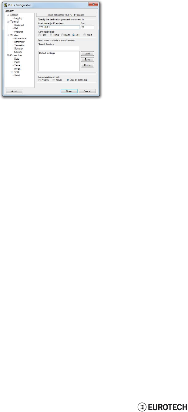
13.2.2 How to login if your development PC is running Windows
ReliaGATE 10-05-x4 eth0 port is configured with the static IP address: 172.16.0.1/24.
To log in using eth0, and complete the following steps:
1. Download, install, and run an SSH client (for example PuTTY)
13 How to log in the Administration Console
ReliaGATE 10-05-34 User Manual Rev 1-0
50 / 62
2. Enter the IP address of your ReliaGATE 10-05-34: 172.16.0.1/24
3. Set the Connection type to ‘SSH’ and Port to ‘22’. Click Open to connect
13.3 How to change your security settings
For security reasons, Eurotech recommends you to change the Linux password after your initial setup.
To change your Linux password, complete the followint steps:
1. At the login prompt, enter username and password:
l
Default username (case sensitive): root
l
Default password (case sensitive): eurotech
2. Use the command
p
a
ss
w
d
to change the ‘root’ password
3. Enter a new ‘root’ account password when prompted
ReliaGATE 10-05-34 User Manual Rev 1-0
14 Eurotech M2M / IoT solutions
51 / 62
14 EUROTECH M2M / IOTSOLUTIONS
Eurotech solutions are a combination of hardware, firmware, operating systems, and programming
frameworks that dramatically accelerate the time to market of M2M / IoT projects and enable customers to
layer their added-value components on a reliable read-to-use infrastructure.
14.1 Everyware Software Framework (ESF)
The ReliaGATE 10-05-34 comes pre-configured with Eurotech’s Everyware Software Framework (ESF).
ESF is a smart application container that enables remote management of IoT gateways and provides a
wide range of APIs allowing you to write and deploy your own IoT application.
ESF runs on top of the Java Virtual Machine (JVM) and leverages OSGi, a dynamic component system for
Java, to simplify the process of writing reusable software building blocks. ESF APIs offer easy access to
the underlying hardware including serial ports, GPS, watchdog, USB, GPIOs, I2C, etc. They also offer
OSGi bundles to simplify the management of network configurations, the communication with IoT servers,
and the remote management of the gateway.
ESF is based on Kura, the popular Eclipse open source project, that was originally contributed to the
Eclipse community by Eurotech.
ESF automatically starts at the boot of the ReliaGATE 10-05-x4.
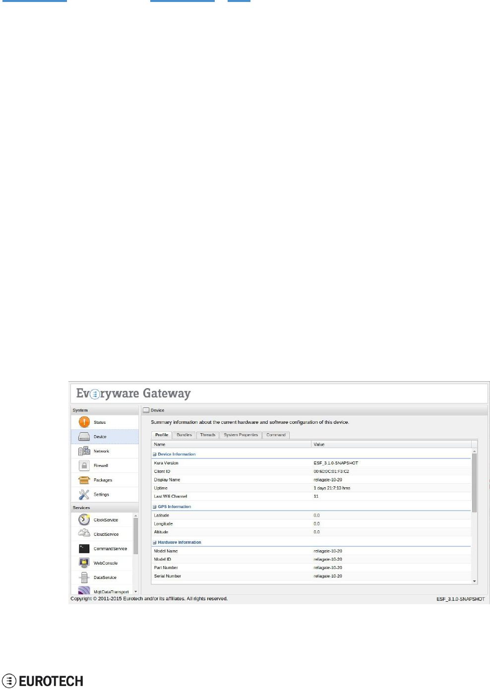
14.2 The ESF Web UI
ESF provides a web-based user interface - "ESF Web UI" - that allows you to:
l
Monitor the gateway status
l
Manage the network configuration
l
Oversee the installed application(s) and services.
The ESF Web UI is available on port 80 of the gateway IP.
The following picture gives you an example of the “ESF Web UI”:
14 Eurotech M2M / IoT solutions
ReliaGATE 10-05-34 User Manual Rev 1-0
52 / 62
14.3 Everyware Cloud (EC)
Eurotech’s Everyware™ Cloud (EC) provides an open and flexible software platform that easily connects
embedded devices to IT systems or to existing applications, immediately solving infrastructure problems
among distributed devices and systems.
With EC you can:
l
Connect any sensor, device or asset to the platform to quickly create new products
l
Dynamically and remotely create and add new services and functionalities to your field devices
l
Configure the platform to analyze data in real-time and trigger immediate alerts
l
Leverage a device-specific message-oriented infrastructure for fast and easy creation of reliable,
device-independent M2M/IoT applications
l
Integrate MVNO Connectivity Platforms to have a single point of management of Connected
Devices and associated SIM cards
l
Enable IoT Analytics through built-in connectors to on-line Dashboards and Analytical Reports
l
Enable IoT Business Application Integrations through native REST APIs
14.4 For further information
For further information about ESF and EC, and to find exhaustive tutorials, refer to the following links:
Information
Available at
ESF Guide
esf.eurotech.com/docs/
Kura website
eclipse.org/kura/
EC Developer’s
Guide
everywarecloud.eurotech.com/doc/ECDevGuide/
EC M2M Integration
Platform
eurotech.com/en/products/software+services/everyware+cloud+m2m+platform
ReliaGATE 10-05-34 User Manual Rev 1-0
15 Mechanical specifications
53 / 62
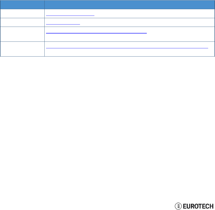
15 MECHANICAL SPECIFICATIONS
15.1 ReliaGATE 10-05-34 mechanical dimensions
The ReliaGATE 10-05-34 electronics are housed in an ABS (Color: blue) and Aluminum enclosure, having
the following dimensions: 112 (L) x 68 (W) x 37 (H); mm (antenna SMA connectors not included).
The following figure shows the dimensions of the ReliaGATE 10-05-34. All dimensions are in millimeters.
Figure 15.1 - ReliaGATE 10-05-34: mechanical
di
me
n
s
ion
s
15 Mechanical specifications
ReliaGATE 10-05-34 User Manual Rev 1-0
54 / 62
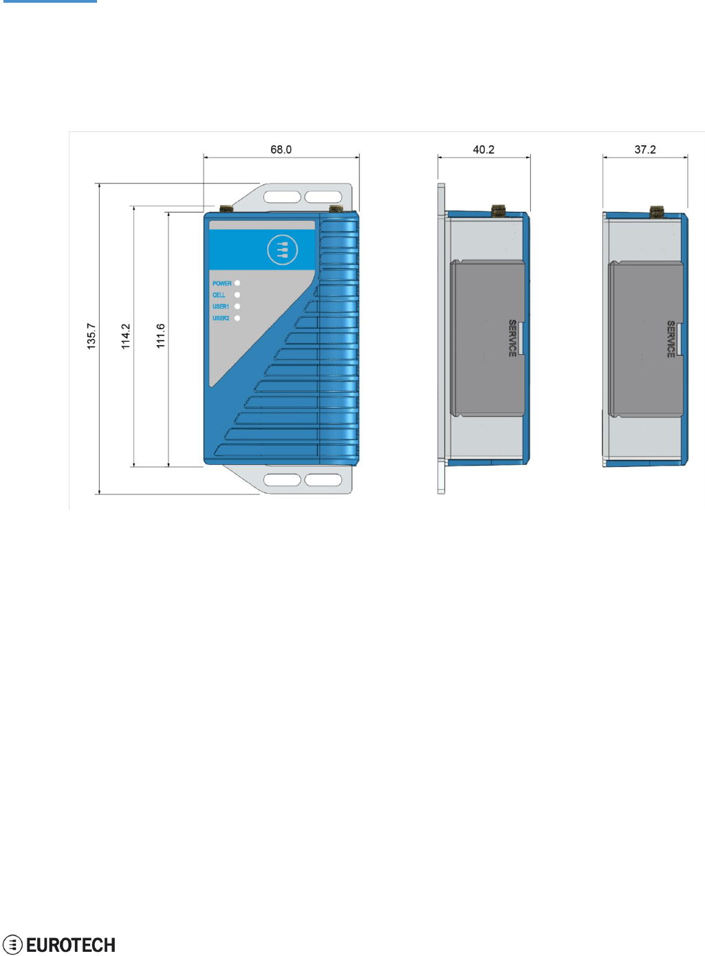
15.2 Mounting bracket mechanical dimensions
The following figure shows the dimensions of the Mounting bracket. All dimensions are in millimeters.
Figure 15.2 - Mounting bracket mechanical dimensions
ReliaGATE 10-05-34 User Manual Rev 1-0
16 How to install the product
55 / 62
16 HOW TO INSTALL THE PRODUCT
To install the ReliaGATE 10-05-34 in place you can use the provided Mounting Bracket.
Optionally, you can use the DIN Rail Mounting Kit to install the ReliaGATE 10-05-x4 on a DIN rail.
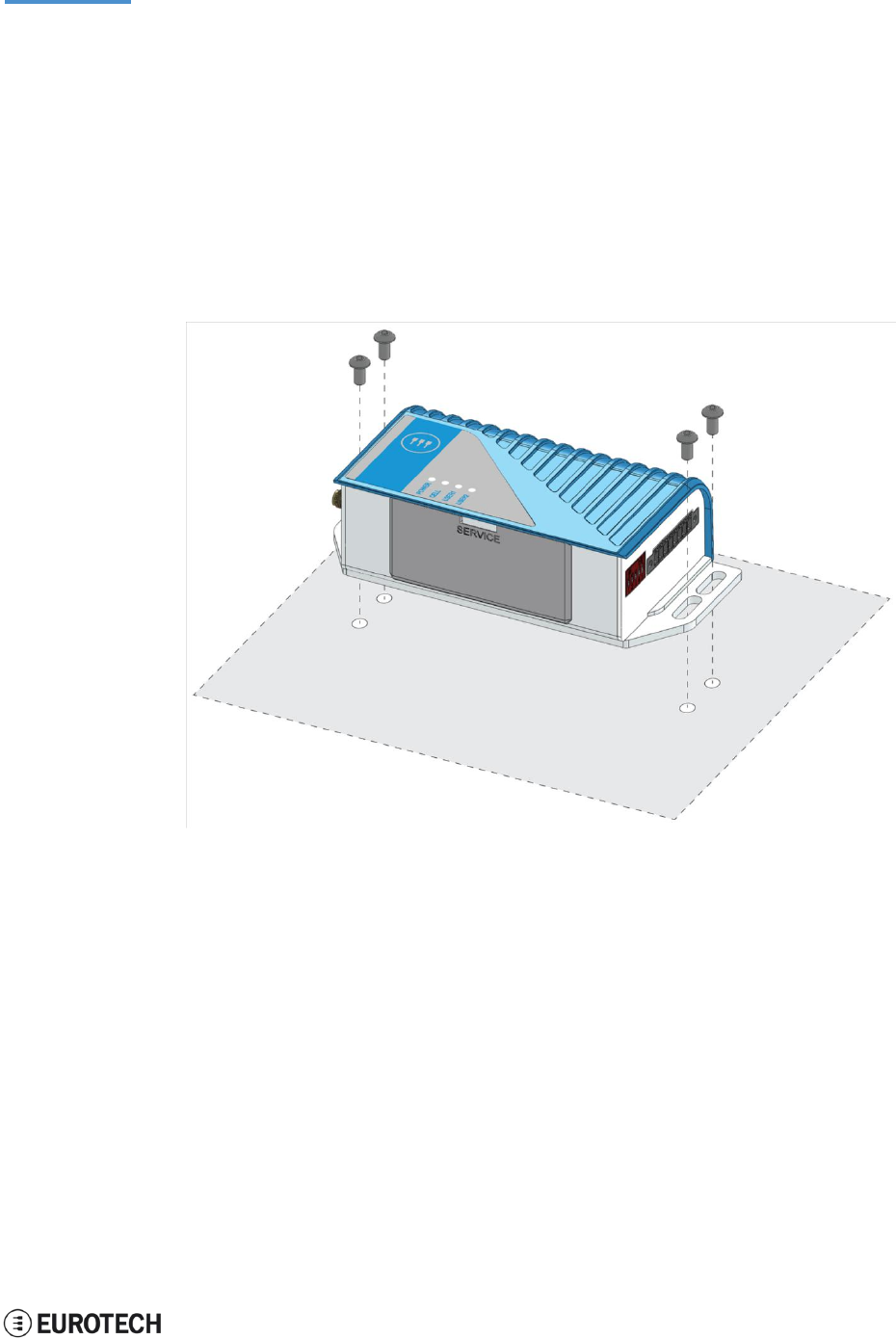
16.1 How to install the ReliaGATE 10-05-34 using the Mounting
Bracket
To install the ReliaGATE 10-05-34 in place using the Mounting Bracket, add all the necessary screws and
locking parts to safely secure the ReliaGATE 10-05-34 in place according to your installation requirements
(for example use M5 screws).
For further information see "Mounting bracket mechanical dimensions" on page 54.
16 How to install the product
56 / 62
ReliaGATE 10-05-34 User Manual Rev 1-0
16.2 Optional: How to install the ReliaGATE 10-05-34 using the
DIN Rail Mounting Kit
Use the optional DIN Rail Mounting Kit to install the ReliaGATE 10-05-34 on a DIN rail.
Before installing the ReliaGATE 10-05-34 on a DIN rail, replace the Mounting Bracket with the optional
DIN Rail Mounting Kit.
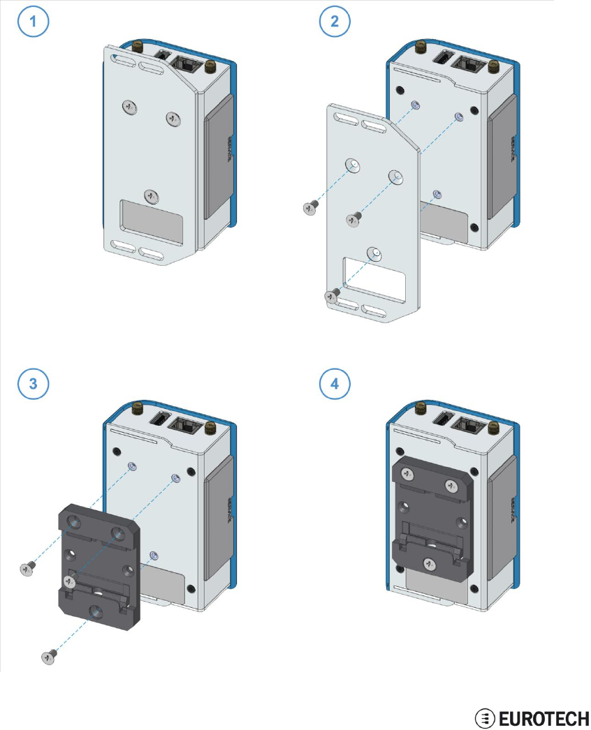
16.2.1 How to replace the Mounting Bracket with the DIN Rail Mounting Kit
To replace the Mounting Bracket with the DIN Rail Mounting Kit, complete the following steps:
1. Remove the 3 screws that hold the Mounting Bracket in place
2. Remove the Mounting Bracket
3. Place the DIN Rail Mounting Kit
4. Fasten the 3 screws removed at Step 1 to hold the DIN Rail Mounting Kit in place
ReliaGATE 10-05-34 User Manual Rev 1-0
16 How to install the product
57 / 62
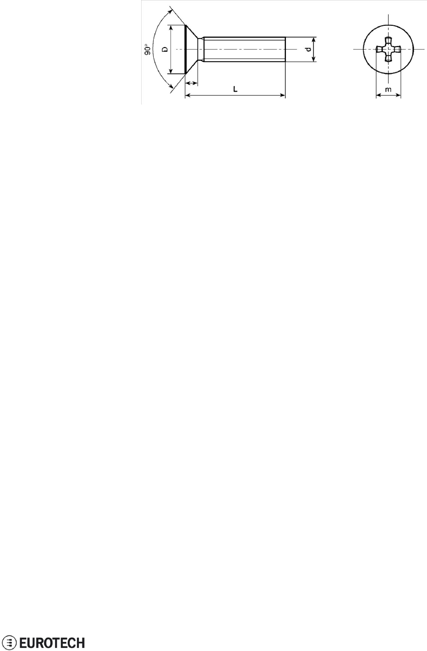
NOTE ABOUT THE 3 SCREWS:
The 3 screws that hold the Mounting Bracket in place have the following features:
l
Cross socket flat head countersunk
l
Fully threaded
l
Stainless steel
16 How to install the product
58 / 62
ReliaGATE 10-05-34 User Manual Rev 1-0
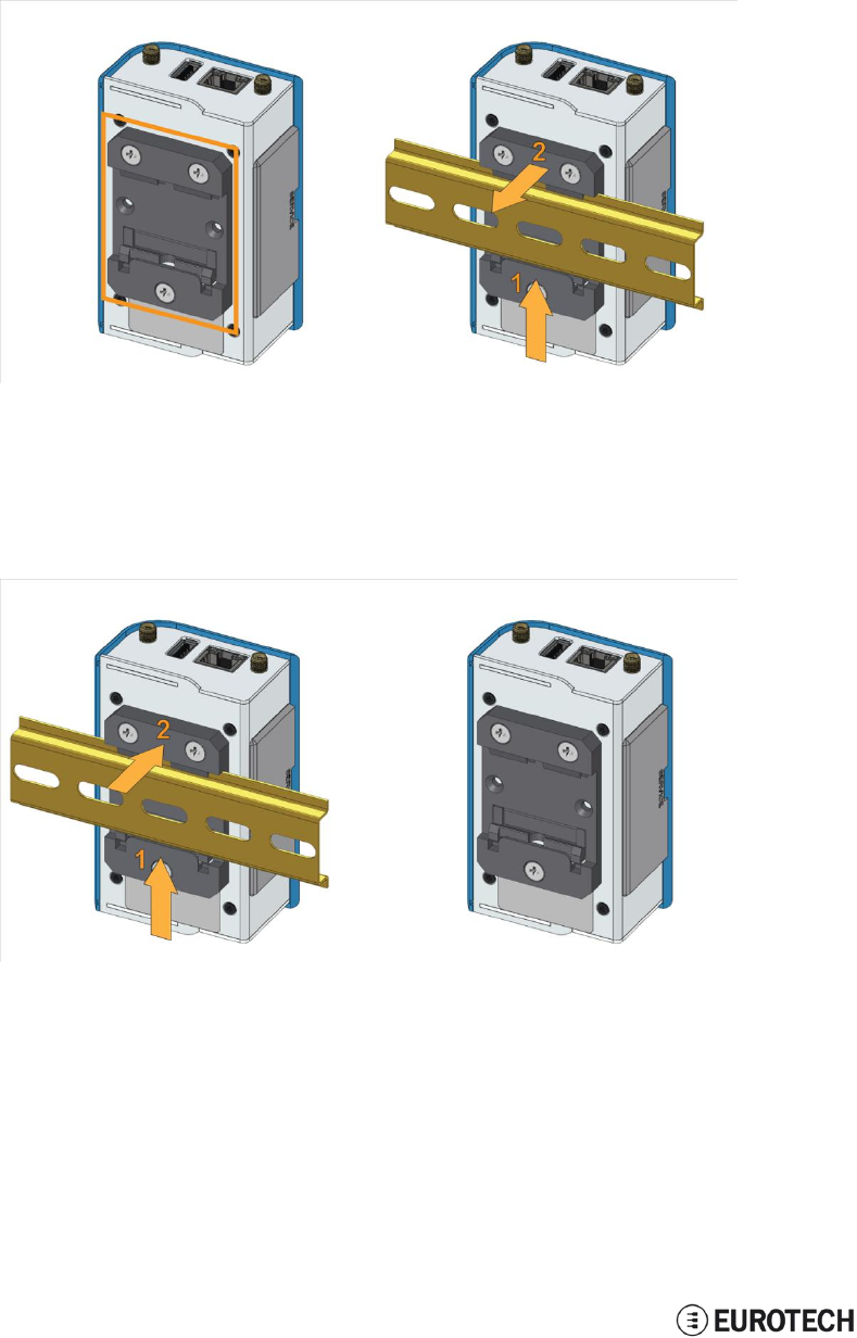
16.2.2 How to install the ReliaGATE 10-05-34 on a DIN rail
Prerequisite: Replace the Mounting Bracket with the DIN Rail Mounting Kit
To install the ReliaGATE 10-05-34 on a horizontal DIN rail, complete the following steps:
1. Hook the lower mobile latches of the mechanical adapter on the lower edge of the DIN rail
2. Push the ReliaGATE 10-05-34 upwards against the DIN rail and lock upper latches of the
mechanical adapter on the upper edge of the DIN rail.
16.2.3 How to remove the ReliaGATE 10-05-34 from a DIN rail
To remove the ReliaGATE 10-05-34 from a horizontal DIN rail, complete the following steps:
1. Push the lower mobile latches of the mechanical adapter upwards to release the upper latches
2. Pull the ReliaGATE 10-05-34 out
59 / 62
ReliaGATE 10-05-34 User Manual Rev 1-0
17 How to maintain the product
17 HOW TO MAINTAIN THE PRODUCT
Periodically inspect the installation of the product to verify its integrity and to ensure proper operation.
Before starting the maintenance of the product, carefully read and understand the instructions
contained in the sections "Important Information" on page 1 and "Safety Instructions" on page 1.
17.1 Use antistatic precautions
NOTICE
PREVENTING ELECTROSTATIC DISCHARGE (ESD)
When handing the product described in this document, always use appropriate
antistatic precautions to avoid damages due to electrostatic discharge.
For example: use a wrist strap or ESD cuff kept in constant contact with bare skin
and attached to an ESD ground.
17.2 Remove the power supply
WARNING
ELECTRIC SHOCK HAZARD
To avoid injuries do not perform any cables connection/disconnection with wet hands
Before starting the maintenance of the product, complete the following steps:
1. Remove the power supply
2. Disconnect all the cables
3. Make sure all the circuits are discharged.
Failure to complete the steps above, may create an electric shock hazard, which could result in
personal injury or loss of life, and / or damage to equipment or other property
17.3 Inspect the installation of the product
To inspect the installation of the product, complete the following steps:
1. Verify that the external surface of the product is clean and not damaged
2. Verify that the LED indicators are not damaged, clean and visible
3. Verify that all the screws, bolts, nuts, etc. are correctly fastened.
17.4 Clean the product
To clean the product, complete the following steps:
1. Use a dry cloth to remove dust and fingerprints from the external casing
2. Do not use detergents, aerosol sprays, solvents or abrasive sponges
3. Use water-based, non-flammable, cleaner products to remove all types of dirt (example: grease, oil,
nicotine etc.)
4. Wipe the chassis with a lint-free cloth
(This page has been intentionally left blank)

ReliaGATE 10.05-34 User Manual Rev
1-0
Notes
NOTES
@EUROTECH 61
/62

WORLD SUPPORT EUROPE AMERICAS ASIA
HEADQUARTERS
EUROTECH
Via Fratelli Solari, 3/a
33020 Amaro (UD) - Italy
Tel: +39 0433.485.411
Fax: +39 0433.485.499
Email: support.it@eurotech.com
Web: www.eurotech.com
ITALY
EUROTECH
Tel: +39 0433.485.411
Fax: +39 0433.485.499
Email: sales.it@eurotech.com
Email: support.it@eurotech.com
Web: www.eurotech.com
UNITED KINGDOM
EUROTECH
Tel: +44 (0) 1223.403410
Fax: +44 (0) 1223.410457
Email: sales.uk@eurotech.com
Email: support.uk@eurotech.com
Web: www.eurotech.com
FRANCE
EUROTECH
Tel: +33 (0)4.72.89.00.90
Fax: +33 (0)4.78.70.08.24
Email: sales.fr@eurotech.com
Email: support.f r@eurotech.com
Web: www.eurotech.com
USA
EUROTECH
Tel: +1 800.541.2003
Tel: +1 301.490.4007
Fax: +1 301.490.4582
Email: sales.us@eurotech.com
Email: support.us@eurotech.com
Web: www.eurotech-inc.com
JAPAN
ADVANET
Tel: +81 86.245.2861
Fax: +81 86.245.2860
Email: sales@advanet.jp
Email: tsupport@advanet.jp
Web: www.advanet.jp
For your Eurotech local contact refer to:
www.eurotech.com/contacts
For the Eurotech Global Support Center refer to:
eurotech.desk.com
For the Eurotech Download Area refer to:
eurotech.com/download
All trademarks and trade names are the property of their respective owners