EVERBEST MACHINERY INDUSTRY DT-989 Digital Multimeter User Manual
SHENZHEN EVERBEST MACHINERY INDUSTRY CO.,LTD. Digital Multimeter Users Manual
User manual.pdf
Please read this manual before switching the unit on.
Important safety information inside.
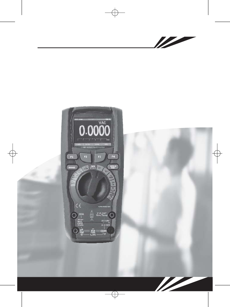
True RMS Digital
Multimeter
User Manual
True RMS Digital
Multimeter
User Manual

True RMS Digital Multimeter User Manual

3
True RMS Digital Multimeter User Manual
Contents
1. Introduction............................................................................................
2. Safety.....................................................................................................
3. Safety Instructions..................................................................................
4. Feature...................................................................................................
5. Measure Function...................................................................................
6. Default Display........................................................................................
7. Setup Options.........................................................................................
8. Specifications.........................................................................................
Page
4
4
6
7
10
18
23
29
4
1. Introduction
Professional True RMS Industrial Digital Multimeter and TFT color LCD display,
providing fast A/D converting sampling time, high accuracy , built-in datalogging
and Trend Capture feactures. It can trace any interrupted problems of the equipments
and watch on without person. It is easy to find and solve the problems of the
production equipments, providing Bluetooth technology and memory the datasheets.
It is much more safe measurements.
This meter measures AC/DC Voltage, AC/DC Current, Resistance, Capacitance,
Frequency(electrical & electronic), Duty Cycle, Diode Test, Insulation Test, and
Continuity plus Thermocouple Temperature. It can store and recall data. It features
a waterproof, rugged design for heavy duty use. Proper use and care of this meter
will provide many years of reliable service
2. Safety
True RMS Digital Multimeter User Manual
WARNING
CAUTION
MAX
This symbol adjacent to another symbol, terminal or operating
device indicates that the operator must refer to an explanation in
the Operating Instructions to avoid personal injury or damage to
the meter.
This symbol indicates a potentially hazardous situation,
which if not avoided, could result in death or serious injury.
This symbol indicates a potentially hazardous situation,
which if not avoided, may result damage to the product.
This symbol advises the user that the terminal(s) so marked must
not be connected to a circuit point at which the voltage with respect
to earth ground exceeds (in this case) 1000 VAC or VDC.
This symbol adjacent to one or more terminals identifies them as
being associated with ranges that may, in normal use, be subjected
to particularly hazardous voltages. For maximum safety, the meter
and its test leads should not be handled when these terminals are
energized.
WARNING
CAUTION
5
True RMS Digital Multimeter User Manual
This symbol indicates that a device is protected throughout by double
insulation or reinforced insulation.
PER IEC1010 OVERVOLTAGE INSTALLATION CATEGORY
OVERVOLTAGE CATEGORY I
OVERVOLTAGE CATEGORY I
Note-
OVERVOLTAGE CATEGORY II
OVERVOLTAGE CATEGORY II
Note-
OVERVOLTAGE CATEGORY III
OVERVOLTAGE CATEGORY III
Note-
OVERVOLTAGE CATEGORY IV
OVERVOLTAGE CATEGORY IV
Note-
Equipment of is equipment for connection to circuits
in which measures are taken to limit the transient overvoltages to an appropriate low
level.
Examples include protected electronic circuits.
Equipment of is energy-consuming equipment to
be supplied from the fixed installation.
Examples include household, office, and laboratory appliances.
Equipment of is equipment in fixed installations.
Examples include switches in the fixed installation and some equipment for
industrial use with permanent connection to the fixed installation.
Equipment of is for use at the origin of the installation.
Examples include electricity meters and primary over-current protection
equipment
6
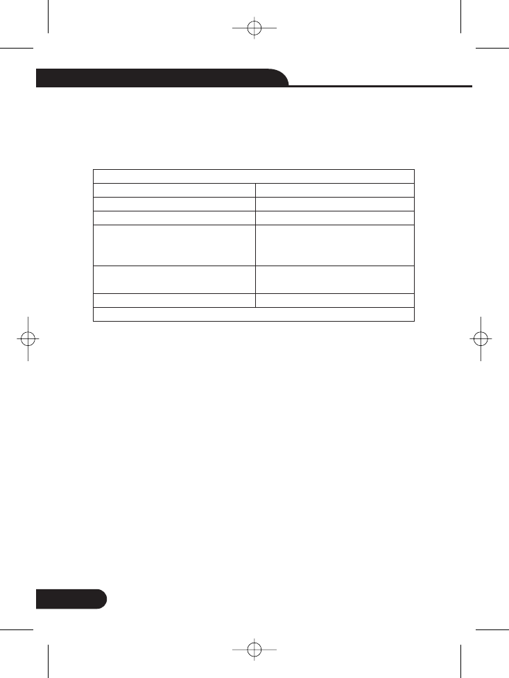
Input Protection Limits
Function
VDCorVAC
mA AC/DC
A AC/DC
Frequency, Resistance, Capacitance,
Duty Cycle, Diode Test, Continuity
Temperature
Surge Protection: 8kV peak per IEC 61010
Maximum Input
1000VDC/AC rms
500mA 1000V fast acting fuse
10A 1000V fast acting fuse
(20A for 30 seconds max every
15 minutes)
1000VDC/AC rms
1000VDC/AC rms
3. Safety Instructions
This meter has been designed for safe use, but must be operated with caution.
The rules listed below must be carefully followed for safe operation.
apply voltage or current to the meter that exceeds the specified maximum:
when working with high voltages.
measure voltage if the voltage on the "COM" input jack exceeds 1000V
above earth ground.
connect the meter leads across a voltage source while the function switch
is in the current, resistance, or diode mode. Doing so can damage the meter.
discharge filter capacitors in power supplies and disconnect the power
when making resistance or diode tests.
turn off the power and disconnect the test leads before opening the covers
to replace the fuse or batteries.
operate the meter unless the back cover and the battery and fuse covers
are in place and fastened securely.
If the equipment is used in a manner not specified by the manufacturer, the
protection provided by the equipment may be impaired.
1-NEVER
2-USE EXTREME CAUTION
3-DO NOT
4-NEVER
5-ALWAYS
6-ALWAYS
7-NEVER
3-
3-
3-
3-
3-
3-
True RMS Digital Multimeter User Manual
7
True RMS Digital Multimeter User Manual
HOLD
REL
RANGE
4. Feature
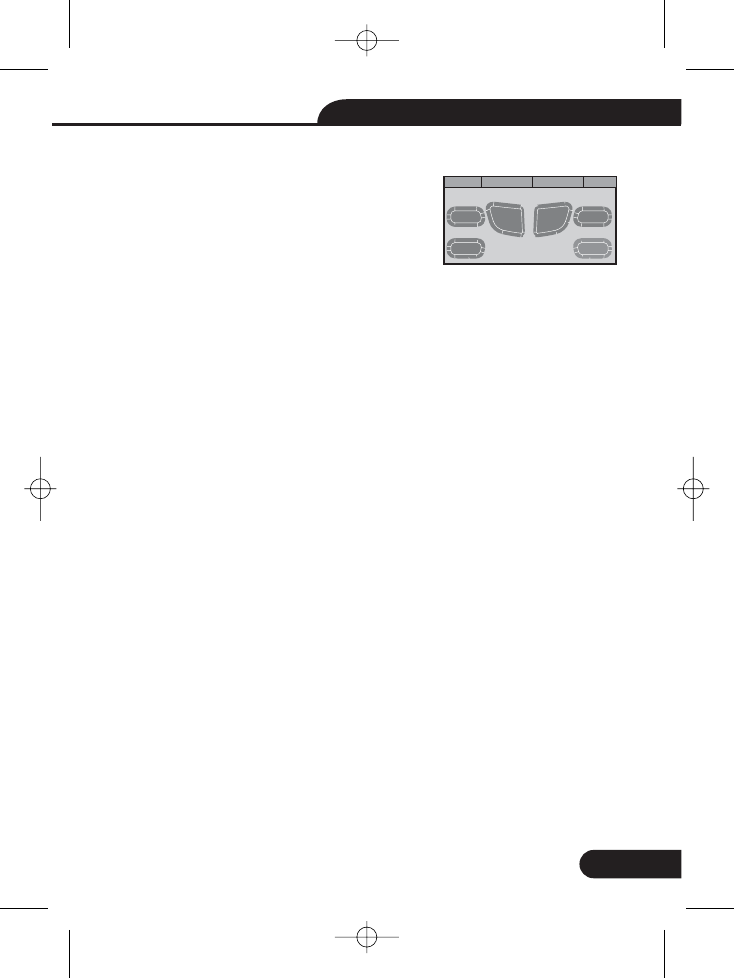
The 6 push buttons on the front of the Meter
activate features that augment the function
using the rotary switch, navigate menus
power to Meter circuits.
Software key. Default switch to Graph measure.
Software key. Default modes related to the rotary switch function
Software key. Default into save mode default Display. And wake up for APO.
Software key. Default modes MINMAX starts and stops MINMAX recording.
Into manual range and select range of the measure. If Pressing the Range
button for greater that 1 second will return Auto Range.
Freezes the present reading in the display and allows the display to be
saved. If Pressing the HOLD/REL button for greater that 1 second will
switch relative mode.
4-1. Understanding the Push Buttons
F1
F2
F3
F4
RANGE
HOLD/REL
selected
or control
RANGE
HOLD/REL
HOLD/REL
GRAPH MODE SAVE MAX
F1 F2 F3 F4
8
True RMS Digital Multimeter User Manual
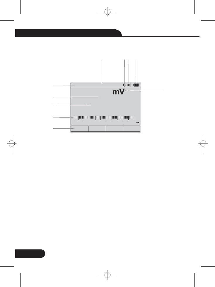
4-2. Understanding the Display
1-Soft key labels Indicates the function of the button just below the displayed label.
2-Bar graph Analog display of the input signal.
3-Minus sign Indicates a negative reading.
4-Displays measurement information about the input signal.
5-Indicates the range the Meter is in and the ranging mode (auto or manual)
6-Time Indicates the time set in the internal clock.
7-Battery level Indicates the charge level batteries.
8-Beeper Indicates the Meter’s beeper is enabled (not associated with the continuity
beeper).
9-Units Indicates the units of measure.
8-
-.400
Auto range 06:32pm
GRAPH MODE SAVE MAX
-500-300 -100 0 100 300 500
5
3
2
1
4
8
9
6 7
10
10-Bluetooth indicates
9
True RMS Digital Multimeter User Manual
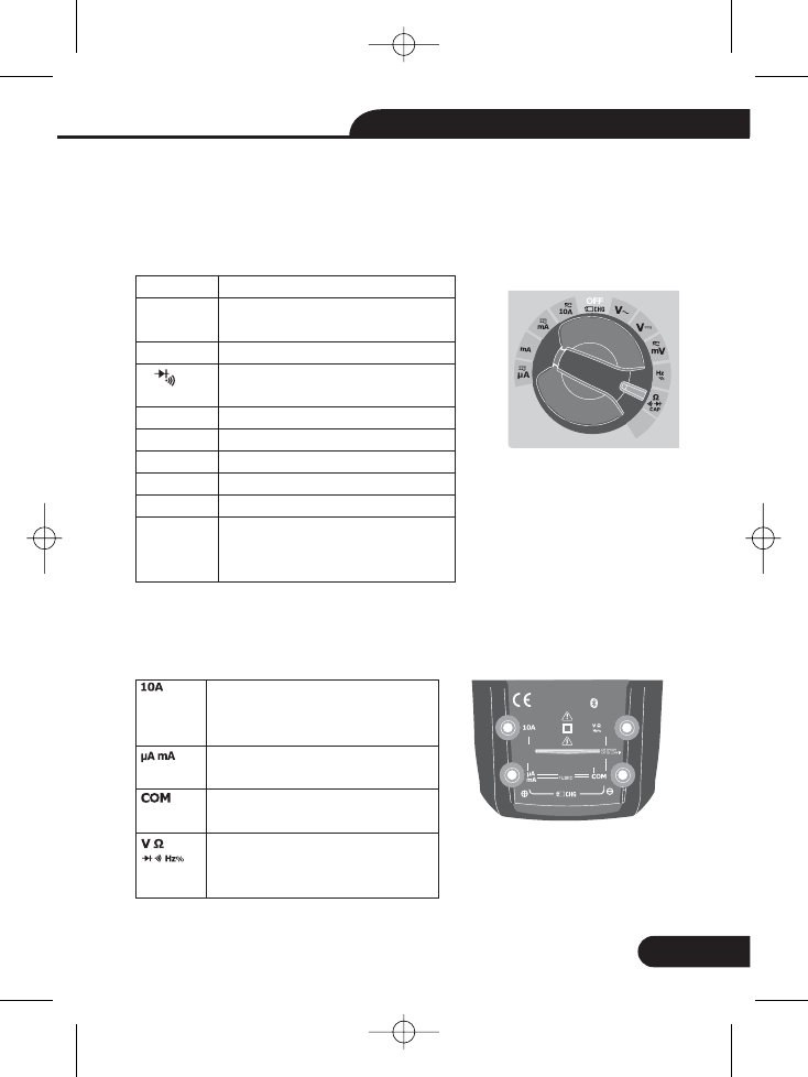
4-3. Understanding the Rotary Switch
4-4. Using the Input Terminals
Select a primary measurement function by positioning the rotary switch to one
of the icons around its perimeter. For each function, the Meter presents a standard
display for that function (range, measurement units, and modifiers). Button choices
made in one function do not carry over into another function.
All functions except current use the VOHMS and COM input terminals. The two
current input terminals
Input for0Ato10.00 A current
(20VA overload for 30 seconds
on, 10 minutes off),
Input for0Ato500mAcurrent
measurements.
Return terminal for all
measurements.
Input for voltage, continuity,
resistance, diode test,
conductance, capacitance.
CAP Temp
Bluetooth
20A fo r
30 sec
MAX
every
15 min
TEMP
CAP
V~
V–
mV
Hz
Temp
A
mA
4-20 mA%
uA
%
AC voltage measurements
DC and AC+DC voltage
measurements.
DC(AC) milli-volts measurements.
Resistance, Diode test,
capacitance and CONTINUITY
measurements.
Frequency measurements.
Temperature measurements .
AC, dc amps measurements.
AC, dc milliamps measurements.
% 4-20MA measurements.
AC, dc microampere
up to 5,000 A.measurements u
Ω CAP
4~20
%
TEMP
°C °F
10A
800mA
10
True RMS Digital Multimeter User Manual
5. Measure Function
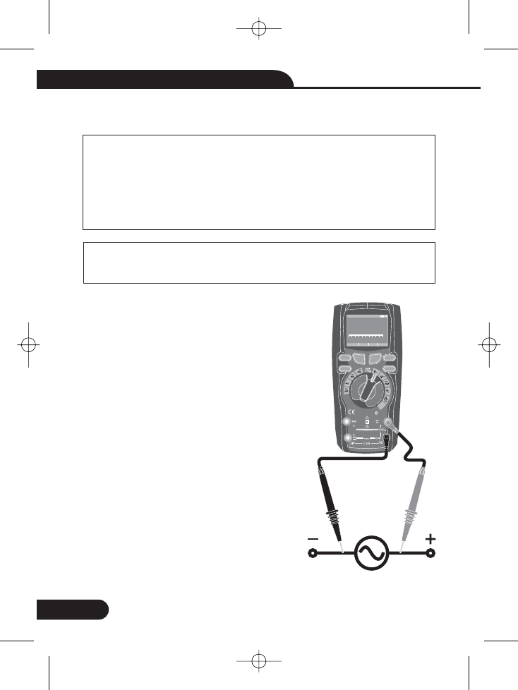
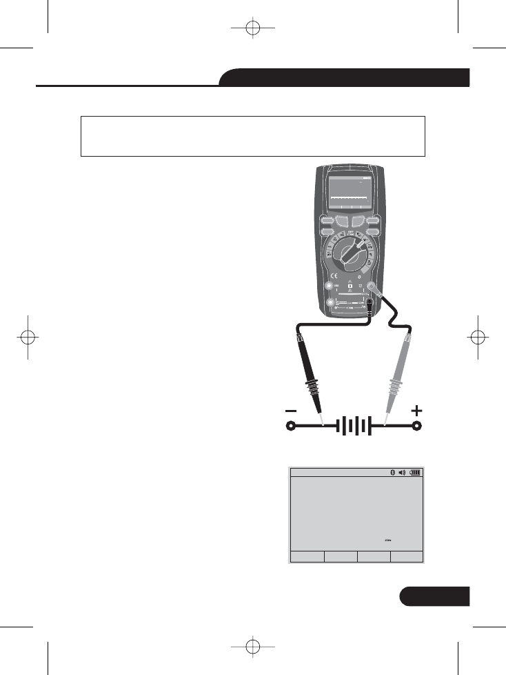
5-1. AC Voltage Measurements
WARNING:
CAUTION:
ON or OFF.
VAC
COM
V
Risk of Electrocution. The probe tips may not be long enough to
contact the live parts inside some 240V outlets for appliances
because the contacts are recessed deep in the outlets. As a
result, the reading may show 0 volts when the outlet actually has
voltage on it. Make sure the probe tips are touching the metal
contacts inside the outlet before assuming that no voltage is
present.
Do not measure AC voltages if a motor on the circuit is being
switched Large voltage surges may occur that can
damage the meter.
1.Set the function switch to the position.
2.Insert the black test lead banana plug into the
negative jack. Insert red test lead banana
plug into the positive jack.
3.Read the voltage in the main display
2.
2.
WARNING:
WARNING:
WARNING:
WARNING:
WARNING:
WARNING:
CAUTION:
CAUTION:
Bluetooth
20Afo r
30sec
MAX
every
15min
TEMP
CAP
F1
HOLD
REL
RANGE
4~20
%
TEMP
°C °F
RANGE SETUP SAVE HOLD
Auto range 00:00
True RMS Multimeter
12 00. 0
V~
012345V~
F2 F3 F4
10A
800mA
11
True RMS Digital Multimeter User Manual
5-2. DC Voltage Measurements
CAUTION:
ON or OFF.
VDC
COM
V
5-3. AC+DC
VDC
COM
MODE
Do not measure DC voltages if a motor on the circuit is being
switched Large voltage surges may occur that can
damage the meter.
1.Set the function switch to the position.
2.Insert the black test lead banana plug into the
negative jack. Insert the red test lead banana
plug into the positive jack.
3.Read the voltage in the display.
1.Set the function switch to the position.
2.Insert the black test lead banana plug into
the negative jack. Insert the red test
lead bananaplug into the positive jack
3.Press the button to indicate “AC+DC”
on the display.
4.Read AC+DC measurement value in the
display.
2.
2.
1.
CAUTION:
CAUTION:
Bluetooth
20Afo r
30sec
MAX
every
15min
TEMP
CAP
4~20
%
TEMP
°C °F
RANGESETUPSAVEHOLD
Auto range 00:00
True RMS Multimeter
100 0.0
V
012345V
CAP
VAC+DC
0.0276
08:12pm
0.0000
0.0276
Auto range
V~
V
GRAPH MODE SAVE MAX
F1
HOLD
REL
RANGE
F2 F3 F4
10A
800mA
12
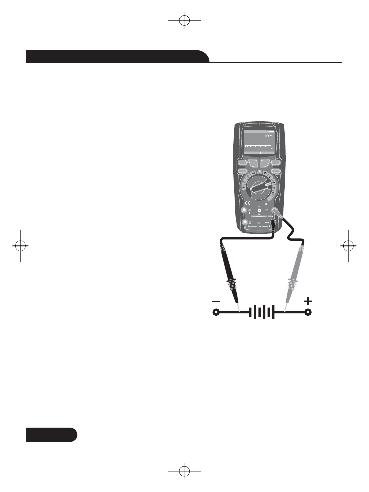
5-4. mV Voltage Measurements
CAUTION:
ON or OFF.
mV
mVDC (mVAC)
COM
V
Do not measure mV voltages if a motor on the circuit is being
switched Large voltage surges may occur that can
damage the meter.
1.Set the function switch to the
position.
2.Press the softkey labeled Mode. switch
.
3.Insert the black test lead banana plug into the
negative jack. Insert the red test lead banana
plug into the positive jack.
4.Read the mV voltage in the display
CAUTION:
CAUTION:
3.
3.
True RMS Digital Multimeter User Manual
Bluetooth
20Afo r
30sec
MAX
every
15min
TEMP
CAP
4~20
%
TEMP
°C °F
RANGE SETUP SAVE HOLD
Auto range 00:00
True RMS Multimeter
10 00. 0
012345
CAP
F1
HOLD
REL
RANGE
F2 F3 F4
10A
800mA
13
True RMS Digital Multimeter User Manual
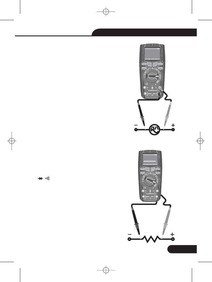
5-5. Frequency Measurements
Hz%
COM
V
5-6. Resistance Measurements
1.Set the function switch to the position.
2.Insert the black test lead banana plug into the
negative jack. Insert the red test lead banana
plug into the positive jack.
3.Read the Frequency in the display
To avoid electric shock, disconnect power to
the unit under test and discharge all capacitors
before taking any resistance measurements.
Remove the batteries and unplug the line cords.
1.Set the function switch to the Ω CAP
COM
Ω
position.
2.Insert the black test lead banana plug into the
negative jack. Insert the red test lead
banana plug into the positive Jack.
3.Read the resistance in the display.
2.
2.
2.
2.
Bluetooth
20Afo r
30sec
MAX
every
15min
TEMP
CAP
4~20
%
TEMP
°C°F
RANGE SETUP SAVE HOLD
Auto range 00:00
TrueRMS Multimeter
0. 0000
Hz
F1
HOLD
REL
RANGE
F2 F3 F4
10A
800mA
Bluetooth
20Afo r
30sec
MAX
every
15min
TEMP
CAP
4~20
%
TEMP
°C°F
RANGE SETUP SAVE HOLD
Auto range 00:00
TrueRMS Multimeter
10 00. 0
Ω
012345Ω
F1
HOLD
REL
RANGE
F2 F3 F4
10A
800mA
14
True RMS Digital Multimeter User Manual
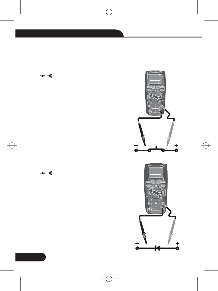
57- . Continuity Check
WARNING:
Ω CAP
COM
OL
To avoid electric shock, disconnect power to the unit under test
and discharge all capacitors before taking any resistance
measurements. Remove the batteries and unplug the line cords.
1.Set the function switch to the
position.
2.Press the softkey labeled Mode. Switch to
C
3.Insert the black test lead banana plug into the
negative jack. Insert the red test lead
banana plug into the positive jack.
4.If the resistance is less than approximately
25Ω, the audible signal will sound. If the circuit
is open, the display will indicate “ ”.
onductace
Ω CAP
2.
3.
3.
3.
3.
WARNING:
WARNING:
Bluetooth
20Afor
30sec
MAX
every
15min
TEMP
CAP
4~20
%
TEMP
°C°F
RANGE SETUP SAVE HOLD
Auto range 00:00
TrueRMS Multimeter
010. 00
Ω
012345
19
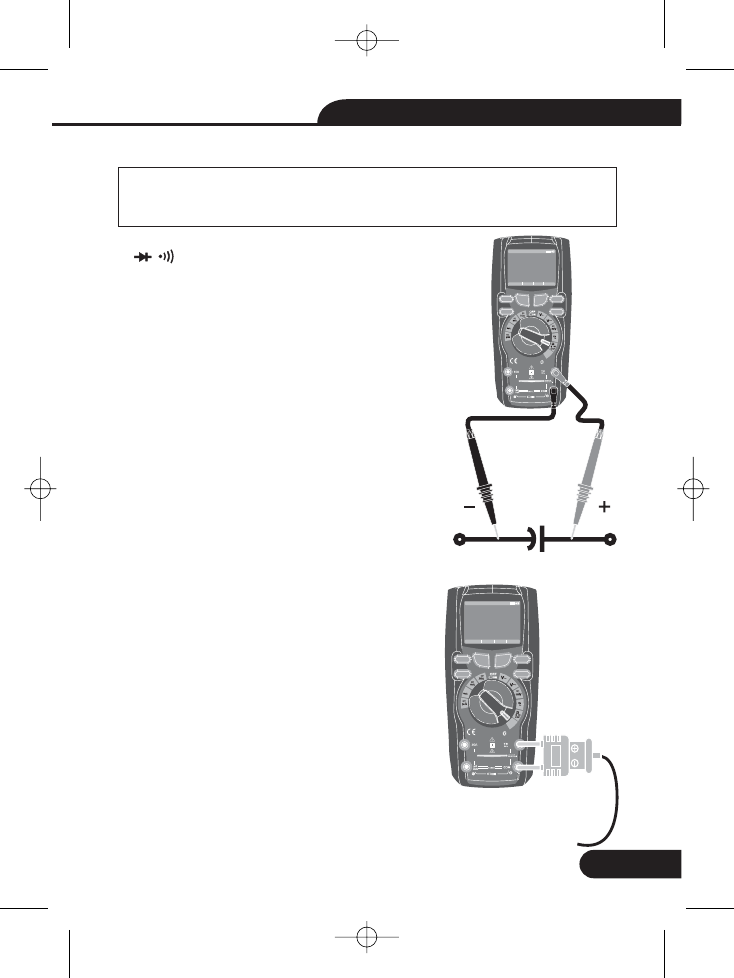
5-8. Diode Test
CAP
COM
V
OL
OL
1.Set the function switch to the
position.
2.Press the softkey labeled Mode. Switch to
Diode.
3.Insert the black test lead banana plug into the
negative jack and the red test lead banana
plug into the positive jack.
4.Forward voltage will typically indicate 0.400 to
3.200V. Reverse voltage will indicate “ ”.
devices will indicate near 0V and an
will indicate “ ” in both polarities.
Shorted
open device
Ω
2.
3.
3.
3.
3.
3.
F1
HOLD
REL
RANGE
F2 F3 F4
Ω
10A
800mA
Bluetooth
20Afor
30sec
MAX
every
15min
TEMP
CAP
4~20
%
TEMP
°C°F
RANGE SETUP SAVE HOLD
Auto range 00:00
TrueRMS Multimeter
0. 0005
V
012345
F1
HOLD
REL
RANGE
F2 F3 F4
V
10A
800mA
15
True RMS Digital Multimeter User Manual
Bluetooth
20Afor
30sec
MAX
every
15min
TEMP
CAP
4~20
%
TEMP
°C°F
RANGE SETUP SAVE HOLD
Auto range 00:00
TrueRMS Multimeter
020. 00
μF
-9. Capacitance Measurements
WARNING:
5
To avoid electric shock, disconnect power to the unit under test
and discharge all capacitors before taking any capacitance
measurements. Remove the batteries and unplug the line cords.
1.Set the rotary function switch to the Ω CAP
position.
2. Press the softkey labeled Mode. Switch to
3.Insert the black test lead banana plug into the
negative jack. Insert the red test lead banana
plug into the positive jack.
4.Read the capacitance value in the Display
CAP
COM
V
WARNING:
WARNING:
Ω CAP
3.
3.
510- . Temperature Measurements
TEMP(°C
or °F)
TEMP
°Cor°F
1.Set the function switch to the
position.
2.Press the softkey labeled Mode. Switch
().
3.Insert the Temperature Probe into the input jacks,
making sure to observe the correct polarity.
4.Read the temper ture in the displaya
1.
1.
1.
F1
HOLD
REL
RANGE
F2 F3 F4
10A
800mA
Bluetooth
20Afo r
30sec
MAX
every
15min
TEMP
CAP
4~20
%
TEMP
°C°F
RANGE SETUP SAVE HOLD
Auto range 00:00
TrueRMS Multimeter
0078 0.
°F
F1
HOLD
REL
RANGE
F2 F3 F4
10A
800mA
16
True RMS Digital Multimeter User Manual
Bluetooth
20Afo r
30sec
MAX
every
15min
TEMP
CAP
4~20
%
TEMP
°C °F
RANGE SETUP SAVE HOLD
Auto range 00:00
True RMS Multimeter
100. 00
A~
012345
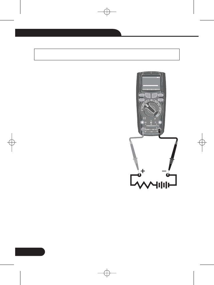
5-11. DC Current Measurements
CAUTION:
COM
μA
μA/mA
mA
MODE
Do not make 20A current measurements for longer than 30
seconds.
Exceeding 30 seconds may cause damage to the meter and/or the test leads.
1.Insert the black test lead banana plug into the
negative jack.
2.For current measurements up to 5000μA DC,
set the function switch to the position
and insert the red test lead banana plug into the
jack.
3.For current measurements up to500mA DC,
set the function switch to the position
and insert the red test lead banana plug into the
μA/mA jack.
4.For current measurements up to 10A DC, set
the function switch to the 10A position
and insert the red test lead banana plug into the
10A jack.
5.Press the button to indicate “DC” on the
display.
6.Read the current in the display.
1.
1.
1.
1.
1.
1.
1.
1.
1.
1.
1.
CAUTION:
F1
HOLD
REL
RANGE
F2 F3 F4
A~
10A
800mA
17
True RMS Digital Multimeter User Manual
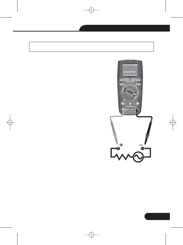
5-12. AC Current Measurements
CAUTION:
COM
μA
μA/mA
mA
μA/mA
10A
MODE
5-13. % 4 – 20mA MEASUREMENTS
4-20mA%
Do not make 10A current measurements for longer than 30
seconds.
Exceeding 30 seconds may cause damage to the meter and/or the test leads.
1.Insert the black test lead banana plug into the
negative jack.
2.For current measurements up to 5000μA AC,set
the function switch to the position and
insert the red test lead banana plug into the
jack.
3.For current measurements up to 500mA AC,set
the function switch to the position
and insert the red test lead banana plug into the
jack.
4.For current measurements up to 10A AC,set the
function switch to the position and
insert the red test lead banana plug into the 10A
jack.
5.Press the button to indicate “AC” on
the display.
6.Read the current in the display.
1.Set up and connect as described for DC mA measurements.
2.Set the rotary function switch to the position.
3.The meter will display loop current as a % with 0mA=-25%, 4mA=0%, 20mA=100%,
and 24mA=125%.
1.
1.
1.
1.
1.
1.
1.
1.
1.
1.
5.
3.
CAUTION:
Bluetooth
20Afo r
30sec
MAX
every
15min
TEMP
CAP
4~20
%
TEMP
°C °F
RANGE SETUP SAVE HOLD
Auto range 00:00
True RMS Multimeter
100. 00
A
012345A
F1
HOLD
REL
RANGE
F2 F3 F4
10A
800mA
18
True RMS Digital Multimeter User Manual
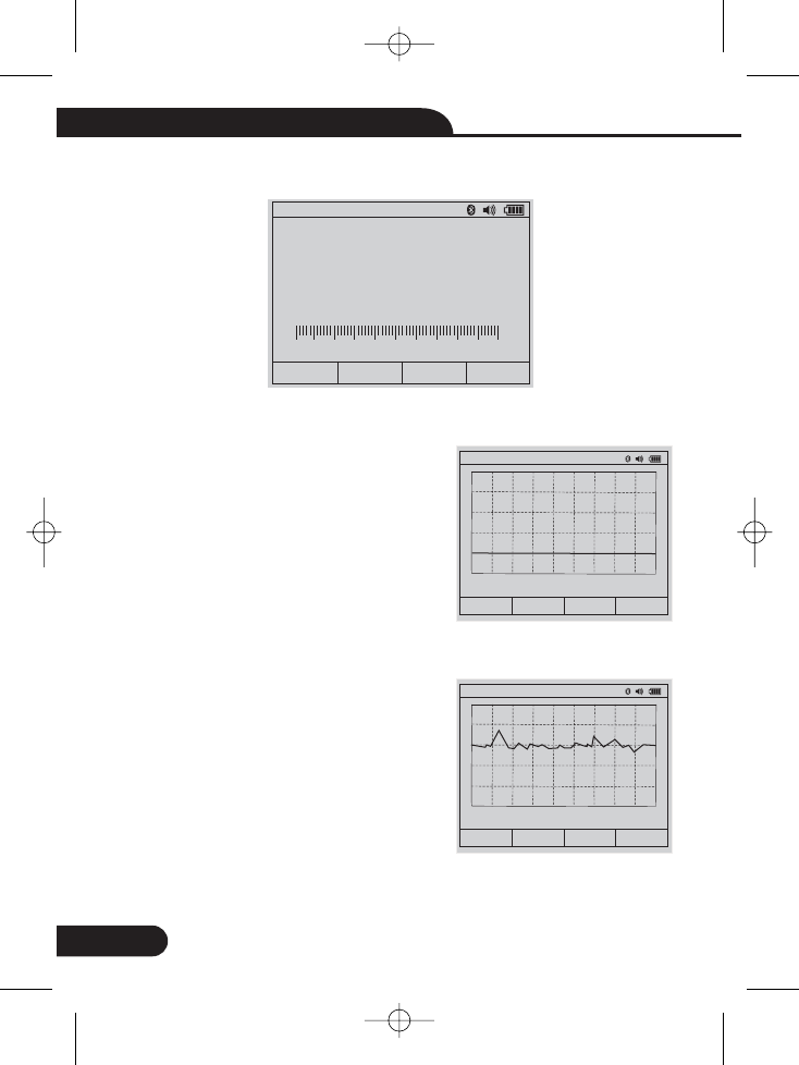
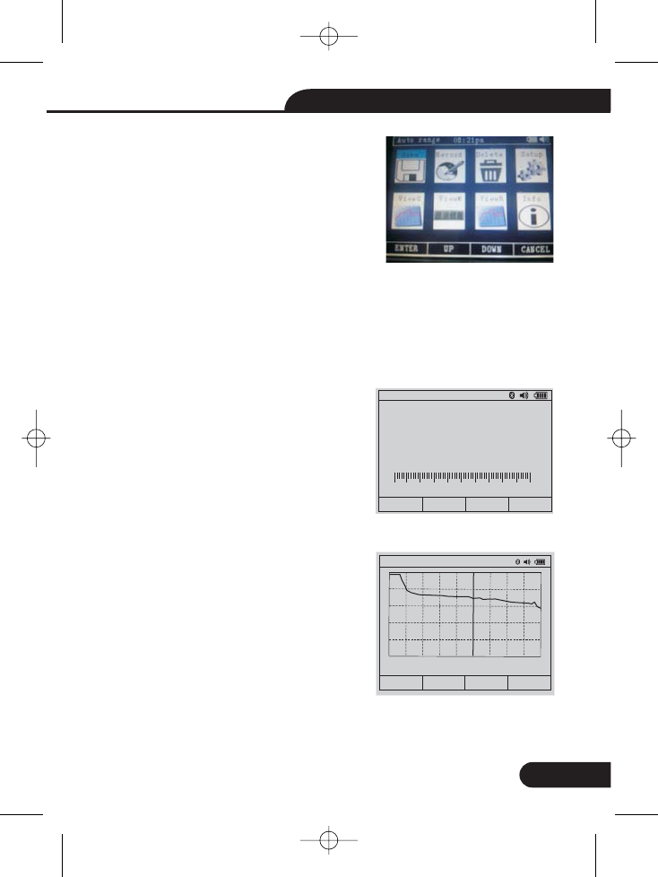
6. Default Display
6-1. Graph Measure
Graph F1Press Software key lable ( ), Meter
will switch to Graph measure.
Press soft key START button. Press FAST or
SLOW soft keys to adjust sampling
rate. Press CANCEL soft key to exit Graph and
return to normal measurement mode
Press STOP soft key.
V~
0 000.0
Auto range 06:32pm
GRAPH MODE SAVE MAX
0.0000 V~
SLOW CANNEL
FAST
Auto range 06:32pm
0
Rate: 0.2 s
Range: 0.01
START
012345V
-2.6000 mV DC
STOP
Auto range 06:32pm
0
Rate: 0.2 s
Range: 500
19
True RMS Digital Multimeter User Manual
Press SAVE soft key to save Graph. Press
BACK soft key to return.
To activate the MAXMIN mode, Press
Software key labled , at measure
mode . As shown in Figure, the Meter displays
eat the top of the measurement page, and the
MAXMIN start date and time along the bottom
of the page. In addition, the recorded maximum,
average, and minimum values appear in the
secondary display with their respective elapsed
times.
To stop a MINMAX recording session, press the Softkey labeled Stop. The summary
information in the display freezes, and the softkeys change function to allow saving
the collected data. Pressing the softkey labeled Close exits the MIN MAX record
session without saving the collected data.
To save the MIN MAX screen data, the MIN MAX session must be ended by
pressing the softkey labeled Stop. Next, press the softkey labeled Save.
6-2. Capturing Minimum and Maximum Values
MAX(F4)
0.0000 V~
BACK
Auto range 06:32pm
0
Rate: 0.2 s
Range: 0.01
SAVE
V~
0.2660
Auto range
08:12pm
STOP PMAX
MAX MIN
MAX
Average
MIN
0.3493 V~
0.2636 V~
0.2548 V~
20
True RMS Digital Multimeter User Manual
6-3. Capturing Peak Values
MINMAX
PMAX(F4)
6-4. Relative Values
HOLD/REL
6-5. Hold Mode
To activate the peak mode, at AC measure
mode , Press Software key labled
.
To activate the relative mode, Press the
button for greater that 1 second.
To freeze the display for any function, press
key HOLD.
Press key save to memory. And press close
return measure.
V~
0.2676
Auto range
08:12pm
STOP MAX
PEAK
PMAX
Average
PMIN
0.6354 V~
0.263 V~
-0.5894 V~
V~
-.04300
Auto range 08:20pm
REL
Reference 0.3079 V~
0.2649 V~
GRAPH MODE SAVE MAX
V~
0.2823
Auto range 06:32pm
SAVE CLOSE
012345V
HOLD
21
True RMS Digital Multimeter User Manual
6-6. Save Function
SAVE(F3)
6-7. Storing Individual Measurement Data
DOWN(F3) Save
ENTER(F1)
6-8. Viewing Memory Data
6-9. Viewing Graph Data
save
DOWN (F3)
Graph
ENTER(F1)
Then pressing the labeled , into save
menu.
For common measurement functions, a snapshot of the screen data is saved by
pressing the softkey labeled Save. Then pressing the labeled to the
select Item, pressing the softkey labeled
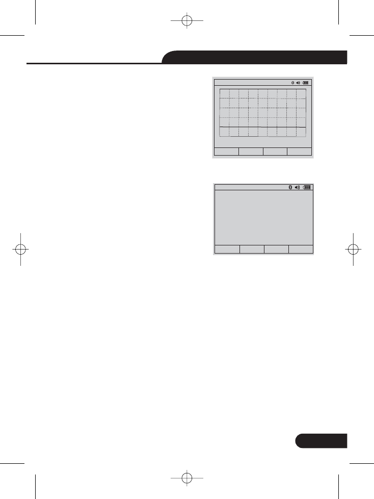
Viewing data stored in the Meter’s memory
is performed through the save menu. Press the
softkey labeled DOWN (F3). Position the menu
selector next to the menu item labeled ViewM.
And pressing the softkey labeled ENTER(F1)
Viewing data stored in the Meter’s memory
is performed through the menu. Press the
softkey labeled . Position the menu
selector next to the menu item labeled .
Pressing the softkey labeled
V~
0.3078
06/02/14 06:32pm
DELETE PREV NEXT BACK
01234
View Men
31.788 MΩ
06/02/14 06:32pm
0
Rate: 0.2 s
Range: 50M
ViewGrap
ENTER PREV NEXT CLOSE
5V
22
True RMS Digital Multimeter User Manual
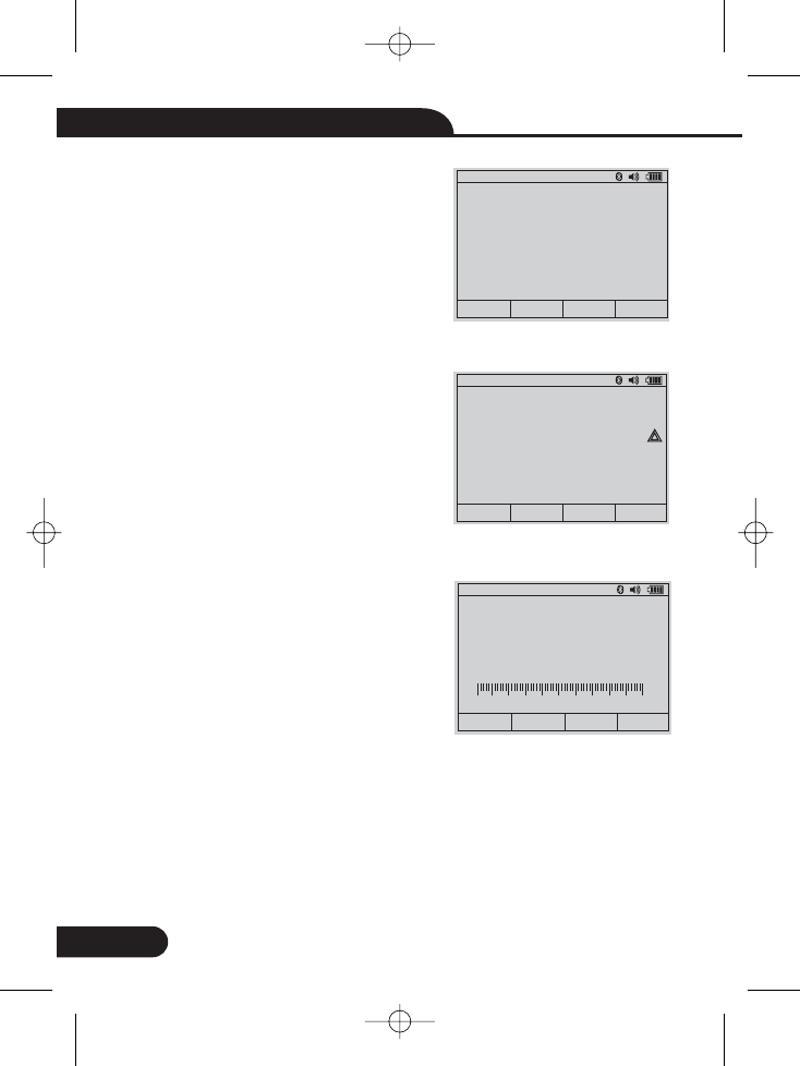
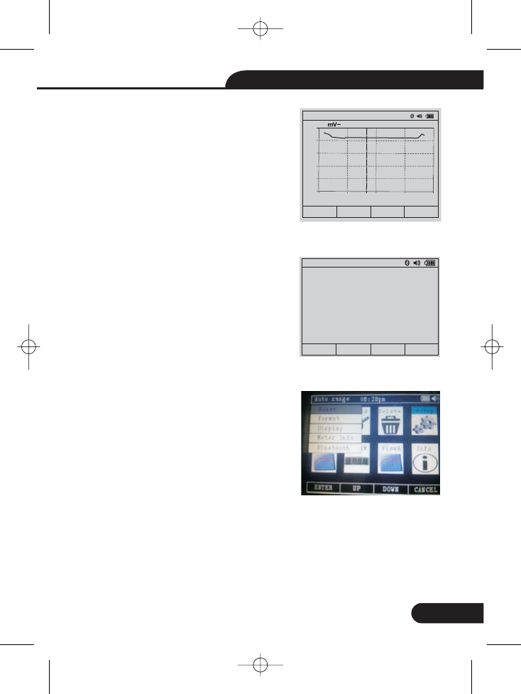
6-10. Recording Measurement Data
Save
DOWN (F3) Record
ENTER(F1) Start
6-11. Viewing Trend Data
DOWN (F3)
ViewR
ENTER(F1)
TREND (F1)
Press the << and >> soft keys to move
cursor
Press the softkey labeled . Then
pressing the labeled to the
select Item, pressing the softkey labeled
. Press the softkey labeled to
start records. The recording session will
continue until the allocated memory is used,
the batteries expire, the rotary switch is moved.
or the session is terminated by pressing the
softkey labeled Stop
Viewing data stored in the Meter’s memory
is performed through the save menu. Press
the softkey labeled . Position the
menu selector next to the menu item labeled
and pressing the softkey labeled
Press the softkey labeled
30.823 MΩ
06/02/14 06:32pm
0
Rate: 0.2 s
Range: 50M
ViewGrap
DELETE BACK
«»
366.55
Auto range 06:32pm
ENTER UP DOWN CLOSER
Set Duration: 00Days 00Hrs 01Min
Set Sample Interval: 00Min 01Sec
Start Record
351.44
Auto range 08:27pm
TREND PREV NEXT CLOSER
Recording
Start Times: 06/02/14 08:26:09pm
Duration: 00days 00hrs 00min 37sec
Samples: 37 Rlog0002
23
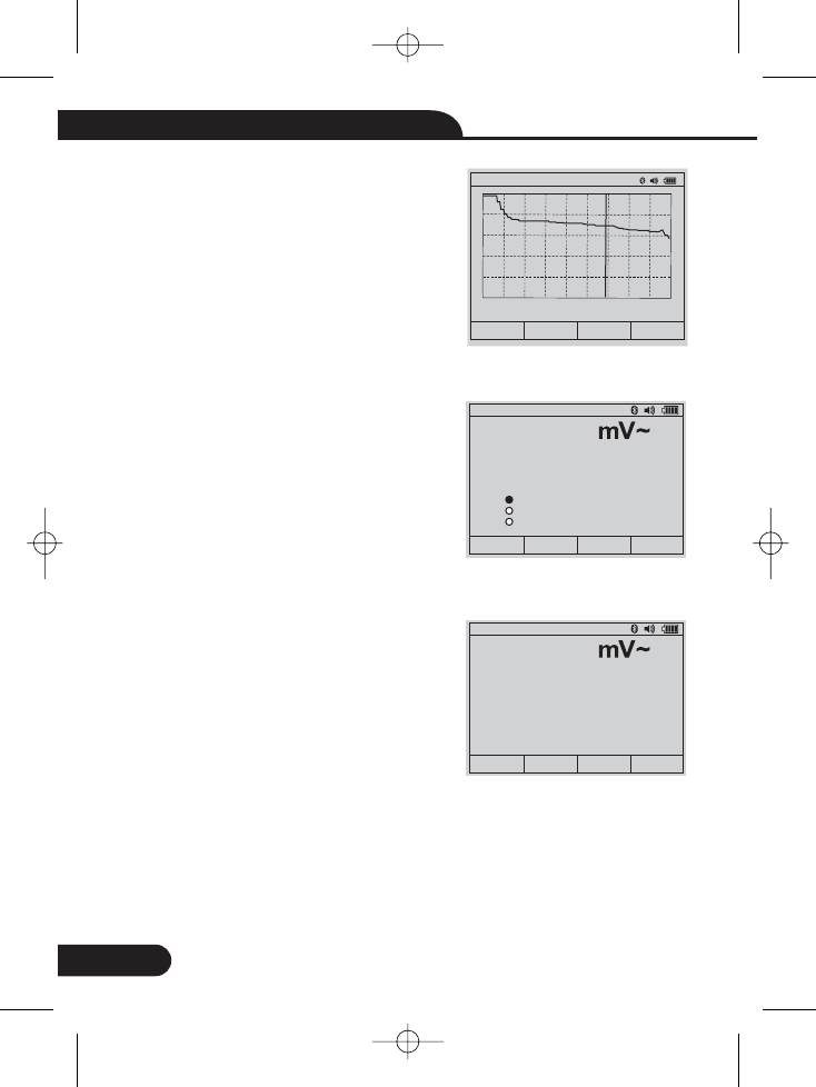
True RMS Digital Multimeter User Manual
Press the + soft key to increase Graph
resolution. Press the >> soft keys to move
cursor.
Viewing data stored in the Meter’s memory
is performed through the menu. Press the
softkey labeled . Position the menu
selector next to the menu item labeled
and pressing the softkey labeled
Viewing data stored in the Meter’s memory
is performed through the menu. Press the
softkey labeled . Position the menu
selector next to the menu item labeled
and pressing the softkey labeled
The Meter’s setup options can be reset to default values through the setup menu.
Open the setup menu. Position the menu selector next to the menu item labeled
and press the key . Then Position the menu selector next to the menu
item labeled SETUP and press the key . Then A message will appear asking to
confirm the reset action. Press the softkey labeled OK to perform the reset.
6-12. Info
save
DOWN (F3)
INFO
ENTER(F1)
save
DOWN (F3)
SETUP
ENTER(F1)
7-1. Resetting Meter
RESET Enter
OK
7. Setup Options
331.99 Mv 08:26:25pm
Auto range 08:27pm
DELETE BACK
+»
400
320
240
160
80
0.0
00:00 00:10 00:20 00:30 00:40
06/02/14 08:26:09pm
Auto range 08:20pm
UP DOWN CLOSE
Fno. Graph- According to graphically display
measurement information
Fno. Mode-Releted to the rotary switch
function.
Fno. Save- Accesses the memory management
menu for saving measurement, setting
up recording sessions, or viewing and
deleting stored measurements from memory.
Fno.
Fno.
Fno.
Fno.
Fno.
24
True RMS Digital Multimeter User Manual
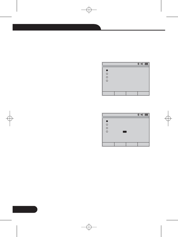
7-2. Meter Info
METER INFO Enter
7-3. Setting Format
FORMAT
Enter
EDIT
7-4. Setting Display
DISPLAY
7-5. Setting Date and Time
Display Enter
The Meter Info selection lists the serial number, firmware version, are displayed.
Open the setup menu. Position the menu selector next to the menu item labeled
and press the key .
Open the setup menu. Position the menu
selector next to the menu item labeled
and press the key . Using the cursor buttons,
move the menu selector next to the menu item
labeled Numeric(Date\Time) format, press the key
to edit, select 0.0000(0,0000) and
MM/DD/YY(DD/MM/YY) and 24 HOUR(12 HOUR)
format.
Open the setup menu. Position the menu selector
next to the menu item labeled and press
the key Enter.
Open the setup menu. Position the menu selector next to the menu item labeled
and press the key .
Next, position the menu selector next to either the Set Date item or Set Time item and
press the softkey labeled Edit.
Auto range 08:32pm
EDIT UP DOWN CLOSER
Beeper
Numeric Format
Date Format
Time Format
Format
Auto range 08:32pm
EDIT UP DOWN CLOSER
Set Date: 06/02/14 dd/mm/yy
Set Time: 08:29:00 pm
Auto Power Off: 00
Foreground: Background:
Select Font: 0
Display
25
True RMS Digital Multimeter User Manual
7-6. Auto Power Off
Display Enter
7-7. Foreground and Background
Display Enter
Foreground and Background
7-8. Set Font
Display Enter
select font
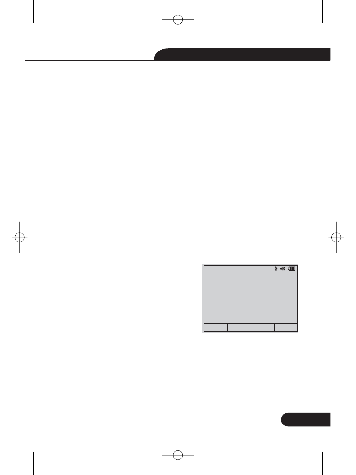
7-9. Bluetooth
Bluetooth
Enter
Open the setup menu. Position the menu selector next to the menu item labeled
and press the key . Then Position the menu selector next to the menu
item labeled POWER OFF and press the key EDIT.
To set Auto Power Off. Use UP and DOWN to adjust the time to one of the preset
values. 0 is disable the timeout feature. Press the softkey labeled OK to set the
selected time. Press the softkey labeled Close to return.
Open the setup menu. Position the menu selector next to the menu item labeled
and press the key . Then Position the menu selector next to the menu
item labeled and press the key OK. Use UP and DOWN
to adjust.
Open the setup menu. Position the menu selector next to the menu item labeled
and press the key . Then Position the menu selector next to the menu
item labeled and press the key EDIT. Use UP and DOWN to adjust.
You can use the Bluetooth communication
link and transfer the contents of a meter’s
memory to a PC.
Open the setup menu. Position the menu
selector next to the menu item labeled
and press the key . “Turn on Bluetooth”
and press OK ,”Turn off Bluetooth” and press
OK.
Auto range 08:32pm
OK CANCEL
Turn on Bluetooth?
26
True RMS Digital Multimeter User Manual
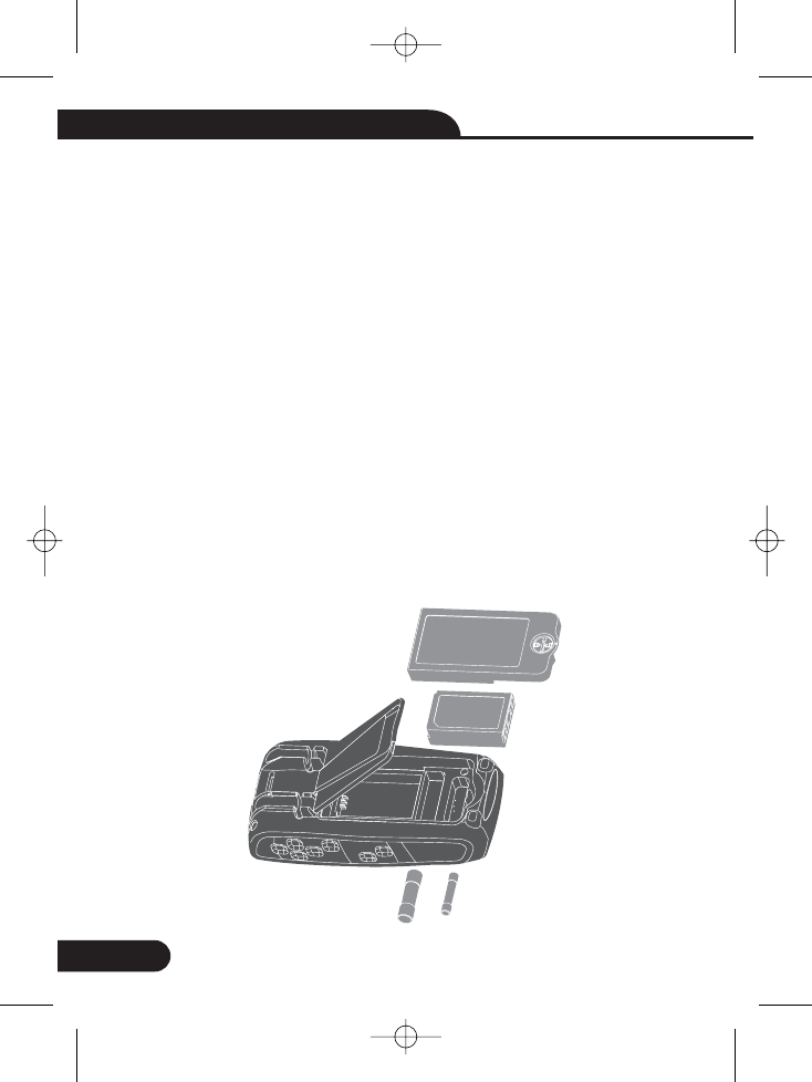
7- .
7-
10 Replacing the Batteries
11 Replacing the Fuses
Refer to Figure and replace the batteries as follows:
1.Turn the Meter off and remove the test leads from the terminals.
2.Remove the battery door assembly by using a standardblade screwdriver to turn
the battery door screw one-half turn counterclockwise.
3. Replace the batteries with 7.4 volt charge batteries Observe proper polarity.
4. Reinstall the battery door assembly and secure it by turning the screw one-half
turn clockwise.
Referring to Figure , examine or replace the Meter's fuses as follows:
1.Turn the Meter off and remove the test leads from the
terminals.
2.Remove the battery door assembly by using a standardblade screwdriver to turn
the battery door screw one-half turn counterclockwise.
3.Remove the fuse by gently prying one end loose, then
sliding the fuse out of its bracket.
4.Install only specified replacement fuses.
5.Reinstall the battery door assembly and secure it by turning the screw one-half
turn clockwise
.
2.
2.
2.
2.
27
True RMS Digital Multimeter User Manual
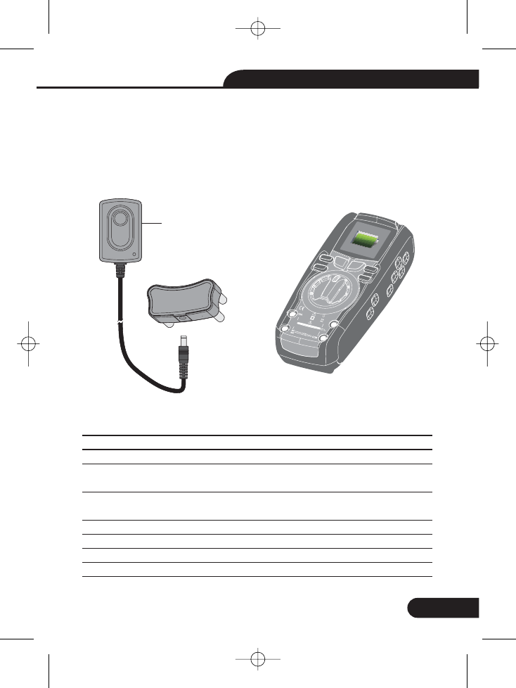
7-12 Li-ion Battery Charge
1.Set the function switch to the OFF/CHG position.
2.Insert the socket into the Meter Input port. And the Adapter connected to the switch
socket.
Then Insert the Adapter into Power socket.
3.Display charge symbol in TFT color LCD display
2.
2.
Enclosure
Shock (Drop Test)
Diode Test
Continuity Check
PEAK
Temperature Sensor
Input Impedance
AC Response
Double molded, waterproof
6.5 feet (2 meters)
Test current of 0.9mA maximum, open circuit
voltage 3.2V DC typical
Audible signal will sound if the resistance is less
than 25 (approx.), test current <0.35mA
Captures peaks >1ms
Requires type K thermocouple
>10M VDC & >9M VAC
True rms
Ω
ΩΩ
Adapter
Tru e RMS Multimeter
F1
HOLD
REL
RANGE
F2 F3 F4
Bluetooth
5
20Afor
30sec
MAX
every
15min
TEMP
CAP

28
True RMS Digital Multimeter User Manual
AC True RMS
ACV Bandwidth
Display
Overrange indication
Auto Power Off
Polarity
Measurement Rate
Low Battery Indication
Battery
Fuses
Operating Temperature
Storage Temperature
Operating Humidity
Storage Humidity
Operating Altitude
Safety
The term stands for “Root-Mean-Square,” which
represents the method of calculation of the voltage
or current value. Average responding multimeters
are calibrated to read correctly only on sine waves
and they will read inaccurately on non-sine wave or
distorted signals. True rms meters read accurately
on either type of signal.
50Hz to 20000Hz
50,000 count TFTLCD
“OL” is displayed
5-30minutes (approximately) with disable feature
Automatic (no indication for positive); Minus (-)
sign for negative
20 times per second, nominal
“ ” is displayed if battery voltage drops below
operating voltage
One 7.2 volt (NEDA 1604) battery
mA, μA ranges; 0.8A/1000V ceramic fast blow A
range; 10A/1000V ceramic fast blow
5ºC to 40ºC (41ºF to 104ºF)
-20ºC to 60ºC
Max 80% up to 87ºF (31ºC) decreasing linearly to
50% at 40ºC (104ºF)
<80% 7000ft. (2000meters) maximum.
This meter is intended for origin of installation use
and protected, against the
users, by double insulation per EN61010-1
and IEC61010-1 2nd Edition (2001) to
Category IV 600V and Category III 1000V; Pollution
Degree 2. The meter also meets UL 61010-1, 2nd
Edition (2004), CAN/CSA C22.2 No. 61010-1 2nd
Edition (2004),and UL 61010B-2-031, 1st Edition (2003)
(-4 F to 140 F)
29
True RMS Digital Multimeter User Manual
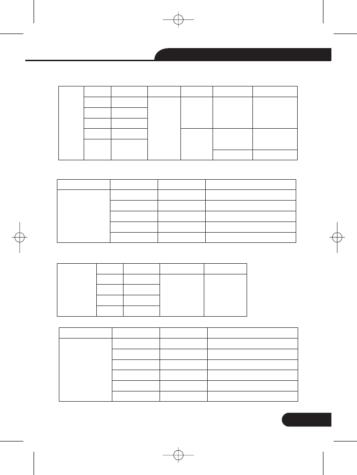
8. Specifications
Range
500mV
5V
50V
500V
1000V
Resolution
0.01mV
0.0001V
0.001V
0.01V
0.1V
50/60HZ
±0.5%
+5
AC
Voltage
<1KHZ
±1.0%
+5
±1.5%
+10
<5kHZ
±3.0%
+5
±3.5%
+10
unspecified
<20KHZ[1]
±5.5%
+20
unspecified
unspecified
Range
500mV[1]
5V
50V
500V
1000V
Resolution
0.01mV
0.0001V
0.001V
0.01V
0.1V
Accuracy
(0.1% + 5digits)
(0.05% + 5digits)
(0.05% + 5digits)
(0.05% + 5digits)
(0.1% + 5)
DC Voltage
[1] When using the relative mode (REL Q) to compensate for offsets.
Function
Range
500 [1]
5k
50k
500k
5M
50M
Ω
Ω
Ω
Ω
Ω
Ω
Resolution
0.01
0.0001k
0.001k
0.01k
0.0001M
0.001M
Ω
Ω
Ω
Ω
Ω
Ω
Accuracy
0.20%+10
0.20%+5
0.20%+5
0.50%+5
0.50%+5
2.0%+10
Function
Resistance
[1] When using the relative mode (REL Q) to compensate for offsets.
5V
50V
500V
1000V
0.0001V
0.001V
0.01V
0.1V
<1KHZ
(1.2% + 20)
(AC+DC) <5KHZ
(3.0% + 20)
[1] upper 10 % of range,
30
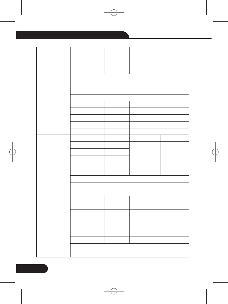
True RMS Digital Multimeter User Manual
Range
-200 to 1350˚C
1. Does not include error of the thermocouple probe.
2. Accuracy specification assumes ambient temperature
stable to ±1˚C.
3. Use a long time, reading will increase 2 ˚C.
500μA
5000μA
50mA
500mA
10A
500μA
5000μA
50mA
500mA
10A
(20A: 30 sec max with reduced accuracy)
All AC current ranges are specified from 5% of range to
100% of range
5nF[1]
50nF
500nF
5μF
50μF
500μF
10mF
[1] With a film capacitor or better, using relative mode
(REL ) to zero residual.Δ
Resolution
0.1˚C
0.01 A
0.1 A
0.001mA
0.01mA
0.001A
0.01 A
0.1 A
0.001mA
0.01mA
0.001A
0.001nF
0.01nF
0.1nF
0.001 F
0.01 F
0.1 F
0.01mF
μ
μ
μ
μ
μ
μ
μ
Accuracy
±(1.0% reading + 3.0°C)
±(1.0% reading +5.4°F)
(probe accuracy not included)
±0.2%+5
±0.2%+5
±0.2%+5
±0.3%+8
±0.5%+8
<1KHZ
±(0.8% + 5)
±(1.5% + 20)
±(1.5% + 8)
±(1.0% + 8)
±(1.5% + 8)
±(1.0% + 8)
±(1.5% + 8)
±(2.5% + 20)
Function
Temp
(type-K)
DC Current
AC Current
Capacitance
<5KHZ
±(3% + 5)
31
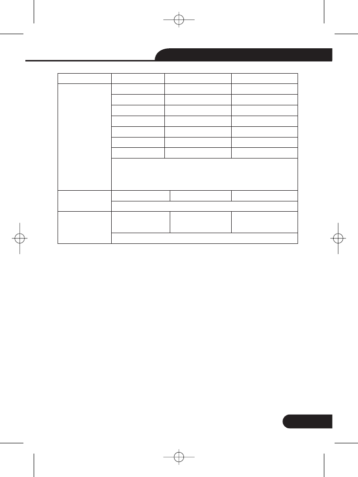
True RMS Digital Multimeter User Manual
Range
50Hz
500Hz
5kHz
50kHz
500kHz
5MHz
10MHz
Sensitivity: 2V rms min. @ 20% to 80% duty cycle and
<100kHz; 5Vrms min @ 20% to 80% duty cycle and
> 100kHz.
10.00Hz-10KHz
Sensitivity:2Vrms
0.1 to 99.90%
Pulse width: 100μs - 100ms, Frequency: 5Hz to 150kHz
Resolution
0.001Hz
0.01Hz
0.0001kHz
0.001kHz
0.01kHz
0.0001MHz
0.001MHz
0.01Hz - 0.001KHz
0.01%
Accuracy
±(0.01% + 5)
±(0.01% + 5)
±(0.01% + 5)
±(0.01% + 5)
±(0.01% + 5)
±(0.01% + 5)
unspecified
±(0.5% reading)
±(1.2% reading
+ 2 digits)
Function
Frequency
(electronic)
Frequency
(electrical)
Duty Cycle
FCC and IC warning:
NOTE:
This device complies with Part 15 of the FCC Rules. Operation is subject to the
following two conditions : (1) this device may not cause harmful interference, and
(2) this device must accept any interference received, including interference that
may cause undesired operation.
Warning: Changes or modifications to this unit not expressly approved by the
party responsible for compliance could void the user’s authority to operate the
equipment.
This equipment has been tested and found to comply with the limits for a
Class B digital device, pursuant to Part 15 of the FCC Rules. These limits are
designed to provide reasonable protection against harmful interference in a
residential installation. This equipment generates, uses and can radiate radio
frequency energy and, if not installed and used in accordance with the instructions,
may cause harmful interference to radio communications. However, there is no
guarantee that interference will not occur in a particular installation. If this equipment
does cause harmful interference to radio or television reception, which can be
determined by turning the equipment off and on, the user is encouraged to try to
correct the interference by one or more of the following measures:
This device complies with FCC and Industry Canada RF radiation exposure limits set forth for general population (uncontrolled exposure).
Rev.151027
True RMS Digital Multimeter User Manual
Reorient or relocate the receiving antenna.
Increase the separation between the equipment and receiver.
Connect the equipment into an outlet on a circuit different from that to which the
receiver is connected.
Consult the dealer or an experienced radio/TV technician for help
This device complies with Industry Canada licence-exempt RSS standard(s).
Operation is subject to the following two conditions: (1) this device may not cause
interference, and (2) this device must accept any interference, including interference
that may cause undesired operation of the device.
Under Industry Canada regulations, this radio transmitter may only operate using
an antenna of a type and maximum (or lesser) gain approved for the transmitter by
Industry Canada. To reduce potential radio interference to other users, the antenna
type and its gain should be so chosen that the equivalent isotropically radiated power
(e.i.r.p.) is not more than that necessary for successful communication.
Conformémentà la réglementationd'Industrie Canada, le présent émetteur
radiopeutfonctionner avec uneantenne d'un type et d'un gain maximal (ouinf érieur)
approuvé pour l'émetteur par Industrie Canada. Dans le but de réduire les risques
de brouillage radioélectriqueàl'intention des autresutilisateurs, il fautchoisir le type
d'antenne et son gain de sorteque la puissance isotroperayonn ée équivalente
(p.i.r.e.) ne dépasse pas l'intensité nécessaireà l'établissement d'une communication
satisfaisante.
Le présent appareilestconforme aux CNR d'Industrie Canada applicables aux
appareils radio exempts de licence. L'exploitationestautorisé e aux deux
conditionssuivantes : (1) l'appareil ne doit pas produire de brouillage, et (2) l'utilisateur
de l'appareildoit accepter tout brouillage radioélectriquesubi,même si le brouillageest
susceptible d'encompromettre le fonctionnement
This device must not be collocated or operating in conjunction with any other antenna or transmitter.