EVERBEST MACHINERY INDUSTRY DT9969 Digital Multimeter(with bluetooth module) User Manual
SHENZHEN EVERBEST MACHINERY INDUSTRY CO.,LTD. Digital Multimeter(with bluetooth module)
User manual
User'sGuide
TrueRMSIndustrialMultimeter
Introduction
Congratulations on your purchase the True RMS Autoranging Multimeter. This meter measures AC/DC Voltage, AC/DC
Current, Resistance, Capacitance, Frequency, Duty Cycle, Diode Test, and Continuity plus Thermocouple Temperature.
It features a waterproof, rugged design for heavy duty use. Proper use and care of this meter will provide many years of
reliable service.
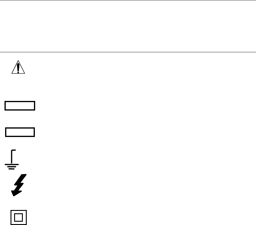
Safety
This symbol adjacent to another symbol, terminal or operating device indicates that the operator
must refer to an explanation in the Operating Instructions to avoid personal injury or damage to the
meter.
This WARNING symbol indicates a potentially hazardous situation, which if not avoided, could
result in death or serious injury.
This CAUTION symbol indicates a potentially hazardous situation, which if not avoided, may result
damage to the product.
This symbol advises the user that the terminal(s) so marked must not be connected to a circuit point
at which the voltage with respect to earth ground exceeds (in this case) 1000 VAC or VDC.
This symbol adjacent to one or more terminals identifies them as being associated with ranges that
may, in normal use, be subjected to particularly hazardous voltages. For maximum safety, the meter
and its test leads should not be handled when these terminals are energized.
This symbol indicates that a device is protected throughout by double insulation or reinforced
insulation.
2.1FCCComplicance
Thisdevicecomplieswithpart15oftheFCCRules.Operationissubjecttothefollowingtwo
conditions:
1.Thisdevicemaynotcauseharmfulinterference.
2.Thisdevicemustacceptanyinterferencereceived,includinginterferencethatmaycause
undesiredoperation.
ThisequipmenthasbeentestedandfoundtocomplywiththelimitsforaClassBdigitaldevice,
pursuanttopart15oftheFCCRules.Theselimitsaredesignedtoprovidereasonableprotection
againstharmfulinterferenceinaresidentialinstallation.Thisequipmentgenerates,uses,andcan
radiateradiofrequencyenergyand,ifnotinstalledandusedinaccordancewiththeinstructions,
maycauseharmfulinterferencetoradiocommunications.However,thereisnoguarantee
thatinterferencewillnotoccurinaparticularinstallation.Ifthisequipmentdoescauseharmful
interferencetoradioortelevisionreception,whichcanbedeterminedbyturningtheequipment
offandon,theuserisencouragedtotrytocorrecttheinterferencebyoneormoreofthe
followingmeasures:
•Reorientorrelocatethereceivingantenna.
•Increasetheseparationbetweentheequipmentandreceiver.
MAX

•Connecttheequipmentintoanoutletonacircuitdifferentfromthattowhichthereceiveris
connected.
•Consultthedealeroranexperiencedradio/TVtechnicianforhelp.
WARNING
Changesormodificationsnotexpresslyapprovedbythepartyresponsibleforcompliancecould
voidtheuser'sauthoritytooperatetheequipment.
ThismeterincludesaBluetoothmodule,itcaneasilytransferthedataindisplaytoyour
smartphone.
HowtoSetup
1.Press"REL"buttonfor2seconds,youwillhear"DiDi",thebluetoothiconwillappearinthe
display.
2.Pairthemetertothesmartphonebyfollowingtheanothermanual.
3.Oncepaired,thedatafromthemeterwillbecontinuouslydisplayedandupdatedonthe
smarphone.
PERIEC1010OVERVOLTAGEINSTALLATIONCATEGORY
OVERVOLTAGECATEGORYI
EquipmentofOVERVOLTAGECATEGORYIisequipmentforconnectiontocircuitsinwhich
measuresaretakentolimitthetransientovervoltagestoanappropriatelowlevel.
Note–Examplesincludeprotectedelectroniccircuits.
OVERVOLTAGECATEGORYII
EquipmentofOVERVOLTAGECATEGORYIIisenergy‐consumingequipmenttobesuppliedfrom
thefixedinstallation.
Note–Examplesincludehousehold,office,andlaboratoryappliances.
OVERVOLTAGECATEGORYIII
EquipmentofOVERVOLTAGECATEGORYIIIisequipmentinfixedinstallations.
Note–Examplesincludeswitchesinthefixedinstallationandsomeequipmentforindustrialuse
withpermanentconnectiontothefixedinstallation.
OVERVOLTAGECATEGORYIV
EquipmentofOVERVOLTAGECATEGORYIVisforuseattheoriginoftheinstallation.
Note–Examplesincludeelectricitymetersandprimaryover‐currentprotectionequipment
CAUTIONS
• Improperuseofthismetercancausedamage,shock,injuryordeath.Readand
understandthisusermanualbeforeoperatingthemeter.
• Alwaysremovethetestleadsbeforereplacingthebatteryorfuses.
• Inspecttheconditionofthetestleadsandthemeteritselfforanydamagebefore
operatingthemeter.
• Usegreatcarewhenmakingmeasurementsifthevoltagesaregreaterthan25VACrms
or35VDC.Thesevoltagesareconsideredashockhazard.
• Warning!ThisisaclassAequipment.Thisequipmentcancauseinterferencesinthe
livingquarters;inthiscasetheoperatorcanberequiredtocarryoutadequatemeasures.
• Alwaysdischargecapacitorsandremovepowerfromthedeviceundertestbefore
performingDiode,ResistanceorContinuitytests.
• Voltagechecksonelectricaloutletscanbedifficultandmisleadingbecauseofthe
uncertaintyofconnectiontotherecessedelectricalcontacts.Othermeansshouldbeusedto
ensurethattheterminalsarenot"live".
• Iftheequipmentisusedinamannernotspecifiedbythemanufacturer,theprotection
providedbytheequipmentmaybeimpaired.
• Thisdeviceisnotatoyandmustnotreachchildren’shands.Itcontainshazardous
objectsaswellassmallpartsthatthechildrencouldswallow.Incaseachildswallowsanyof
them,pleasecontactaphysicianimmediately
• Donotleavebatteriesandpackingmateriallyingaroundunattended;theycanbe
dangerousforchildreniftheyusethemastoys
• Incasethedeviceisgoingtobeunusedforanextendedperiodoftime,removethe
batteriestopreventthemfromdraining
• Expiredordamagedbatteriescancausecauterizationoncontactwiththeskin.Always,
therefore,usesuitablehandglovesinsuchcases
• Seethatthebatteriesarenotshort‐circuited.Donotthrowbatteriesintothefire.

SAFETYINSTRUCTIONS
This meter has been designed for safe use, but must be operated with caution. The rules listed below must be carefully
followed for safe operation.
1. NEVER apply voltage or current to the meter that exceeds the specified maximum:
InputProtectionLimits
FunctionMaximumInput
VDCorVAC1000VDC/ACrms
mAAC/DC500mA1000Vfastactingfuse
AAC/DC10A 1000V fast acting fuse (20A for 30 seconds max every 15
minutes)
Frequency,Resistance,Capacitance,
DutyCycle,DiodeTest,Continuity1000VDC/ACrms
Temperature 1000VDC/ACrms
2. USE EXTREME CAUTION when working with high voltages.
3. DO NOT measure voltage if the voltage on the "COM" input jack exceeds 600V above earth ground.
4. NEVER connect the meter leads across a voltage source while the function switch is in the current, resistance, or
diode mode. Doing so can damage the meter.
5. ALWAYS discharge filter capacitors in power supplies and disconnect the power when making resistance or diode
tests.
6. ALWAYS turn off the power and disconnect the test leads before opening the covers to replace the fuse or
batteries.
7. NEVER operate the meter unless the back cover and the battery and fuse covers are in place and fastened
securely.
8. If the equipment is used in a manner not specified by the manufacturer, the protection provided by the equipment
may be impaired.
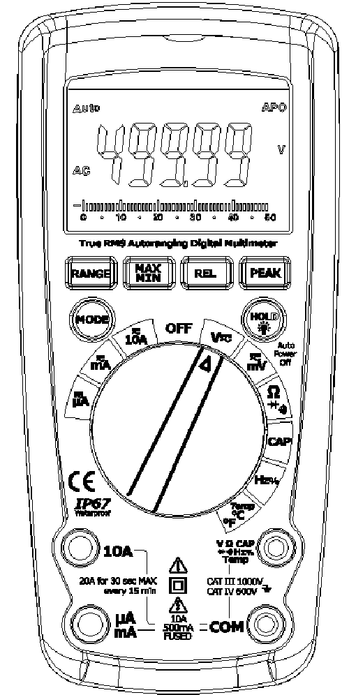
Controls and Jacks
1. 50,000 count LCD
2. MAX/MIN button
3. RANGE button
4. MODE button
5. Function switch
6. mA, µA and 10A input jacks
7. Bluetooth LED indicator
8. RELATIVE and Bluetooth Power button
9. PEAK button
10. HOLD and (Backlight) button
11. Positive input jack
12. COM input jack
Note: Tilt stand and battery compartment are on rear of unit.
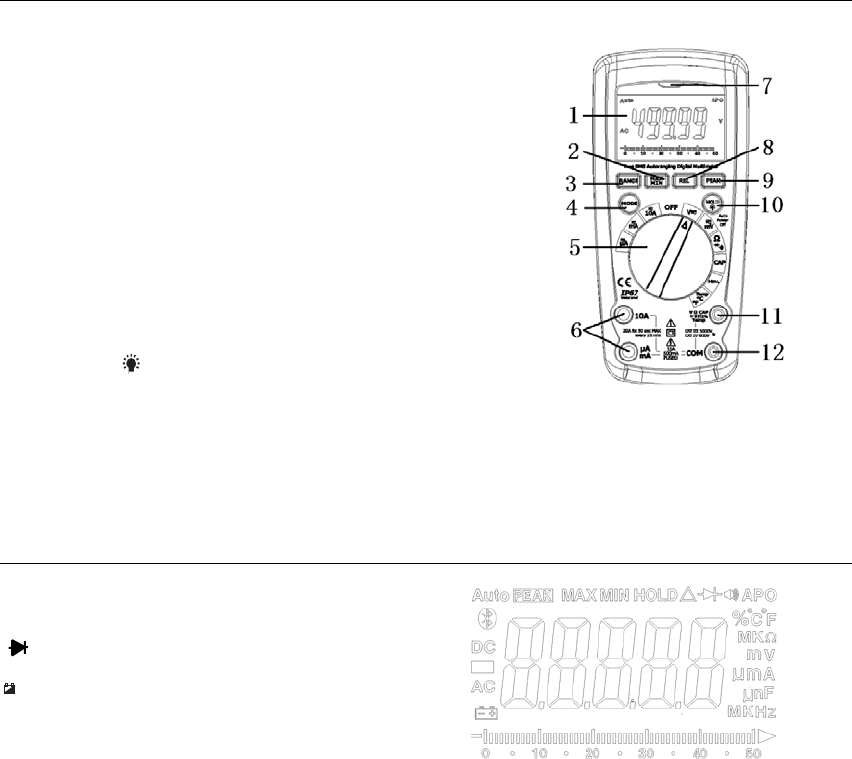
Symbols and Enunciators
•))) Continuity
Diode test
+
Low Battery
n nano (10-9) (capacitance)
µ micro (10-6) (amps, cap)
m milli (10-3) (volts, amps)
A Amps
k kilo (103) (ohms)
F Farads (capacitance)
M mega (106) (ohms) APO Auto Power Off
Ω Ohms PEAK Peak
Hz Hertz (frequency) V Volts
% Percent (duty ratio) REL Relative
AC Alternating current AUTO Autoranging
DC Direct current HOLD Display hold
ºF Degrees Fahrenheit ºC Degrees Centigrade
MAX Maximum MIN Minimum
Operating Instructions
WARNING:Riskofelectrocution.High‐voltagecircuits,bothACandDC,areverydangerousand
shouldbemeasuredwithgreatcare.
1. ALWAYS turn the function switch to the OFF position when the meter is not in use.
2. If “OL” appears in the display during a measurement, the value exceeds the range you have selected. Change to a
higher range.
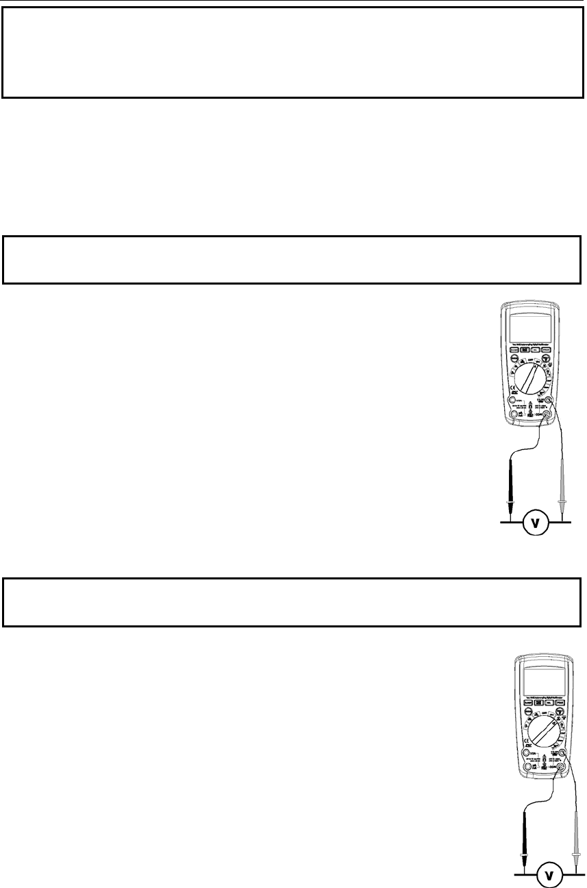
AC/DCVOLTAGEMEASUREMENTS
CAUTION: Do not measure DC voltages if a motor on the circuit is being switched ON or OFF. Large voltage
surges may occur that can damage the meter.
1. Rotate the function switch to the V position.
2. Press the MODE button to display “DC” or “AC” on the LCD
3. Insert the black test lead banana plug into the negative COM jack. Insert the red test lead
banana plug into the positive V jack.
4. Touch the black test probe tip to the negative side of the circuit.
Touch the red test probe tip to the positive side of the circuit.
5. Read the voltage in the display.
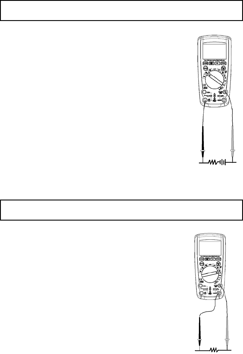
DC/ACMILLIVOLTMEASUREMENTS
CAUTION: Do not measure DC/AC voltages if a motor on the circuit is being switched ON or OFF. Large voltage
surges may occur that can damage the meter.
1. Rotate the function switch to the mV DC-AC position.
2. Insert the black test lead banana plug into the negative COM jack.
Insert the red test lead banana plug into the positive V jack.
3. PresstheMODEbuttontoselect“DC”or“AC”millivolts.
4. Touch the black test probe tip to the negative side of the circuit.
Touch the red test probe tip to the positive side of the circuit.
5. Read the voltage in the display.
AC/DC CURRENT MEASUREMENTS
CAUTION: Do not make 20A current measurements for longer than 30 seconds. Exceeding 30 seconds may
cause damage to the meter and/or the test leads.
1. Insert black test lead banana plug into the negative COM jack.
2. For current measurements up to 5000µA DC, set the function switch to the µA position
and insert the red test lead banana plug into the µA/mA jack.
3. For current measurements up to 500 mA DC, set the function switch to the mA position
and insert the red test lead banana plug into the µA/mA jack.
4. For current measurements up to 10A DC, set the function switch to the 10A/HZ/% position
and insert the red test lead banana plug into the 10A jack.
5. Press the MODE button to indicate “DC” or “AC” on the display.
6. Remove power from the circuit under test, then open up the circuit at the point where you
wish to measure current.
7. Touch the black test probe tip to the negative side of the circuit. Touch the red test probe
tip to the positive side of the circuit.
8. Apply power to the circuit.
9. Read the current in the display.
RESISTANCE MEASUREMENTS
WARNING: To avoid electric shock, disconnect power to the unit under test and discharge all capacitors before
taking any resistance measurements. Remove the batteries and unplug the line cords.
1. RotatethefunctionswitchtotheΩposition.
2. InserttheblacktestleadbananaplugintothenegativeCOMjack.
InserttheredtestleadbananaplugintothepositiveΩjack.
3. PresstheMODEbuttontoindicate“Ω” onthedisplay.
4. Tou chthetestprobetipsacrossthecircuitorpartundertest.Itisbest
todisconnectonesideofthepartundertestsotherestofthecircuit
willnotinterferewiththeresistancereading.
5. Readtheresistanceinthedisplay.
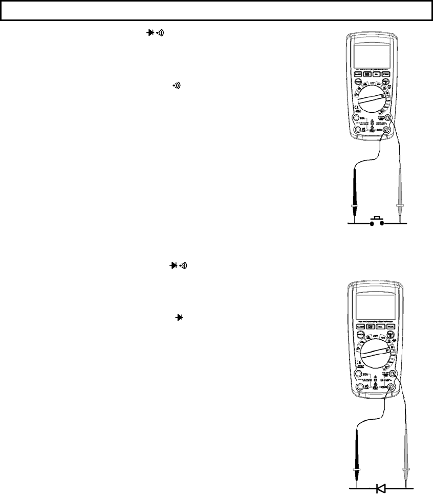
CONTINUITY CHECK
WARNING: To avoid electric shock, never measure continuity on circuits or wires that have voltage on them.
1. Rotate the function switch to the Ω position.
2. Insert the black lead banana plug into the negative COM jack.
Insert the red test lead banana plug into the positive Ω jack.
3. PresstheMODEbuttontoindicate“ " onthedisplay
4. Touch the test probe tips to the circuit or wire you wish to check.
5. If the resistance is less than approximately 35Ω, the audible signal will sound. If the
circuit is open, the display will indicate “OL”.
DIODE TEST
1. Rotate the function switch to the green Ω position.
2. Insert the black test lead banana plug into the negative COM jack and the red test lead
banana plug into the positive V jack.
3. PresstheMODEbuttontoindicate““and“V” onthe
display.
4. Touch the test probes to the diode under test. Forward voltage will typically indicate
0.400 to 0.700V. Reverse voltage will indicate “OL”. Shorted devices will indicate near
0V and an open device will indicate “OL” in both polarities.
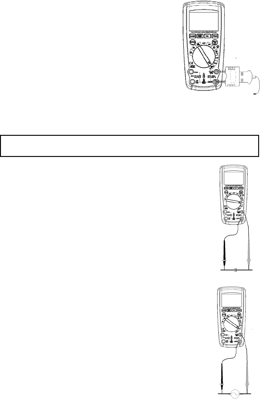
THERMOCOUPLE TEMPERATURE MEASUREMENTS
1. Rotate the function switch to the TYPE K position.
2. Insert the Temperature Probe into the input jacks, making sure to observe the
correct polarity.
3. Press the MODE button to indicate “ºF” or “ºC”
4. Touch the Temperature Probe head to the part whose temperature you wish
to measure. Keep the probe touching the part under test until the reading
stabilizes.
5. Read the temperature in the display.
Note: The temperature probe is fitted with a type K mini connector.
A mini connector to banana connector adaptor is supplied for connection to
the input banana jacks.
Note: The temperature range of the supplied thermocouple probe is -20 to 250°C (-4 to 482°F)
CAPACITANCE MEASUREMENTS
WARNING: To avoid electric shock, disconnect power to the unit under test and discharge all capacitors before
taking any capacitance measurements. Remove the batteries and unplug the line cords.
1. Rotate the function switch to the CAP position.
2. Insert the black test lead banana plug into the negative COM jack.
Insert the red test lead banana plug into the positive V jack.
3. Touch the test leads to the capacitor to be tested.
4. Read the capacitance value in the display
FREQUENCY(DUTYCYCLE)MEASUREMENTS
1. RotatetthefunctionswitchtotheHz/%position.
2. InserttheblackleadbananaplugintothenegativeCOMjackandthered
testleadbananaplugintothepositiveHzjack.
3. Tou chthetestprobetipstothecircuitundertest.
4. Readthefrequencyonthedisplay.
5. PresstheMODEbuttontoindicate“%”.
6. Readthe%dutycycleinthedisplay.
AUTORANGING/MANUAL RANGE SELECTION
When the meter is first turned on, it automatically goes into AutoRanging. This automatically selects the best range for
the measurements being made and is generally the best mode for most measurements. For measurement situations
requiring that a range be manually selected, perform the following:
1. Press the RANGE key. The “AUTO” display indicator will turn off.
2. Press the RANGE key to step through the available ranges until you select the range you want.
3. To exit the Manual Ranging mode and return to Autoranging, press and hold the RANGE key for 2 seconds.
Note: Manual ranging does not apply for the Temperature functions.
MAX/MIN
1. Press the MAX/MIN key to activate the MAX/MIN recording mode. The display icon "MAX" will appear. The meter
will display and hold the maximum reading and will update only when a new “max” occurs.
2. Press the MAX/MIN key again and the display icon "MIN" will appear. The meter will display and hold the minimum
reading and will update only when a new “min” occurs.
3. To exit MAX/MIN mode press and hold the MAX/MIN key for 2 seconds.

Relative mode
The relative measurement feature allows you to make measurements relative to a stored reference value. A reference
voltage, current, etc. can be stored and measurements made in comparison to that value. The displayed value is the
difference between the reference value and the measured value.
1. Perform the measurement as described in the operating instructions.
2. Press and Hold the REL button to store the reading in the display and the "REL" indicator will appear on the display.
3. The display will now indicate the difference between the stored value and the measured value.
4. Press and Hold the REL button to exit the relative mode.
PEAK HOLD
The Peak Hold function captures the peak AC voltage or current. The meter can capture negative or positive peaks as
fast as 1 millisecond in duration. Press the PEAK button. “PEAK MAX” will appear in the display, Press the PEAK
key again and the display icon "PEAK MIN" will appear. The meter will update the display each time a higher
positive and nagetive peak occurs. Press and hold the PEAK button for 2 seconds to exit the mode.
DISPLAY BACKLIGHT
Press the HOLD/ key for >2 second to turn the backlight on. The backlight will automatically turn off after 10
seconds.
HOLD
The hold function freezes the reading in the display. Press the HOLD key momentarily to activate or to exit the HOLD
function.
LOW BATTERY INDICATION
When the low battery
+
icon appears in the display, the battery should be replaced.
AUTO POWER OFF
The auto off feature will turn the meter off after 15 minutes. To disable the auto power off feature, hold down the
MODE button and turn the meter on. “APO d” will appear in the display. Turn the meter off and then on again to
re-enable the auto power off feature.

Maintenance
WARNING: To avoid electric shock, disconnect the test leads from any source of voltage before removing the back
cover or the battery or fuse covers.
WARNING: To avoid electric shock, do not operate your meter until the battery and fuse covers are in place and
fastened securely.
This MultiMeter is designed to provide years of dependable service, if the following care instructions are performed:
1. KEEP THE METER DRY. If it gets wet, wipe it off.
2. USE AND STORE THE METER IN NORMAL TEMPERATURES. Temperature extremes can shorten the life of the
electronic parts and distort or melt plastic parts.
3. HANDLE THE METER GENTLY AND CAREFULLY. Dropping it can damage the electronic parts or the case.
4. KEEP THE METER CLEAN. Wipe the case occasionally with a damp cloth. DO NOT use chemicals, cleaning
solvents, or detergents.
5. USE ONLY FRESH BATTERIES OF THE RECOMMENDED SIZE AND TYPE. Remove old or weak batteries so
they do not leak and damage the unit.
6. IF THE METER IS TO BE STORED FOR A LONG PERIOD OF TIME, the batteries should be removed to prevent
damage to the unit.
BATTERYINSTALLATION
WARNING: To avoid electric shock, disconnect the test leads from any source of voltage before removing the battery
cover.
1. Turn power off and disconnect the test leads from the meter.
2. Open the rear battery cover by removing two screws (B) using a Phillips head screwdriver.
3. Insert the battery into battery holder, observing the correct polarity.
4. Put the battery cover back in place. Secure with the screws.
WARNING: To avoid electric shock, do not operate the meter until the battery cover is in place and fastened
securely.
NOTE: If your meter does not work properly, check the fuses and batteries to make sure that they are still good and that
they are properly inserted.
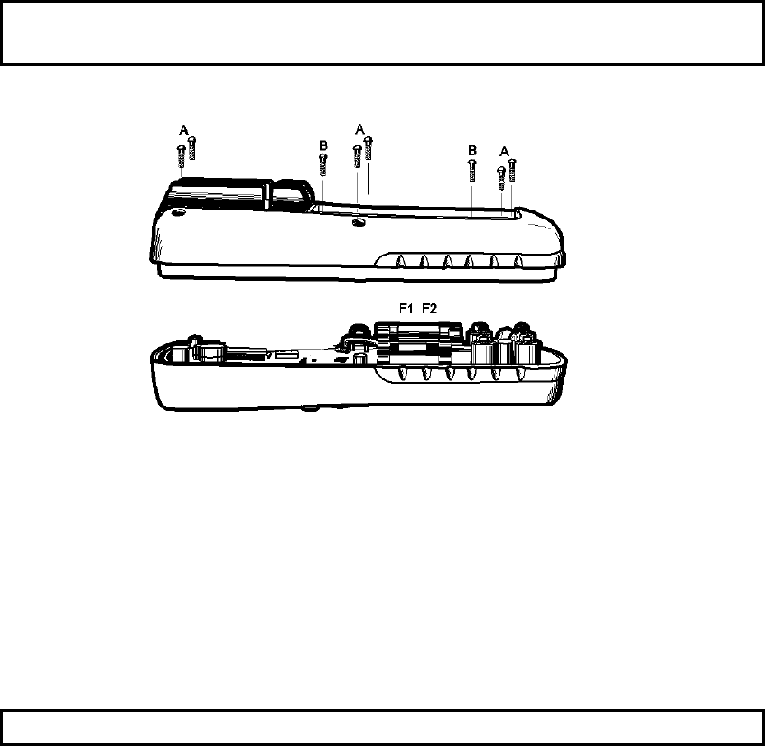
REPLACING THE FUSES
WARNING: To avoid electric shock, disconnect the test leads from any source of voltage before removing the meter
cover.
1. Disconnect the test leads from the meter.
2. Remove the battery cover (two “B” screws) and the battery.
3. Remove the six “A” screws securing the rear cover.
4. Gently remove the old fuse and install the new fuse into the holder.
5. Always use a fuse of the proper size and value (0.5A/1000V fast blow for the 600 mA range 10A/1000V fast blow
for the 10A range
6. Replace and secure the rear cover, battery and battery cover.
WARNING: To avoid electric shock, do not operate your meter until the fuse cover is in place and fastened securely.

Function Range Resolution Accuracy
DC Voltage
50mV 0.001mV ±(0.06% reading + 9digits)
500mV 0.01mV
±(0.06% reading + 4 digits)
5V 0.0001V
50V 0.001V
500V 0.01V
1000V 0.1V ±(0.1% reading + 5 digits)
AC Voltage
50 to 1000Hz
50mV 0.001mV
±(1.0% reading + 9 digits)
500mV 0.01mV
5V 0.0001V
50V 0.001V
500V 0.01V
1000V 0.1V
All AC voltage ranges are specified from 5% of range to 100% of range
DC Current 500μA 0.01μA
±(1.0% reading + 3 digits)
5000μA 0.1μA
50mA 0.001mA
500mA 0.01mA
10A 0.001A
(20A: 30 sec max with reduced accuracy)
AC Current
50 to 1000Hz
500μA 0.01μA
±(1.5% reading + 9 digits)
5000μA 0.1μA
50mA 0.001mA
500mA 0.01mA
10A 0.001A
(20A: 30 sec max with reduced accuracy)
All AC voltage ranges are specified from 5% of range to 100% of range
NOTE: Accuracy is stated at 65oF to 83oF (18oC to 28oC) and less than 75% RH.

Function Range Resolution Accuracy
Resistance 50Ω 0.001Ω
±(0.3% reading + 9 digits)
500Ω 0.01Ω
5kΩ 0.0001kΩ
±(0.3% reading + 4 digits)
50kΩ 0.001kΩ
500kΩ 0.01kΩ
5MΩ 0.0001MΩ
50MΩ 0.001MΩ ±(2.0% reading + 10 digits)
Capacitance
±(3.5% reading + 40 digits)
500nF 0.01nF
5μF 0.0001μF
±(3.5% reading + 10 digits)
50μF 0.001μF
500μF 0.01μF
5000µF 0.1µF
±(5% reading + 10 digits)
50mF 0.001mF
Frequency
50Hz 0.001Hz
±(0.1% reading + 1 digits)
500Hz 0.01Hz
5kHz 0.0001kHz
50kHz 0.001kHz
500kHz 0.01kHz
5MHz 0.0001MHz
50MHz 0.001MHz
Sensitivity: 0.8V rms min. @ 20% to 80% duty cycle and <100kHz; 5Vrms min @ 20% to 80% duty cycle and >
100kHz.
Duty Cycle 0.1 to 99.90% 0.01% ±(1.2% reading + 2 digits)
Pulse width: 100µs - 100ms, Frequency: 5Hz to 150kHz
Tem p
(type-K)
-58.0 to 2192.0°F 0.1°F ±(1.0% reading + 4.5°F)
(probe accuracy not included)
-50.0 to 1200.0°C 0.1°C ±(1.0% reading + 2.5°C)
(probe accuracy not included)

Enclosure Double molded, Waterproof (IP67)
Diode Test Test current of 0.9mA maximum, open circuit voltage 2.8V DC typical
Continuity Check Audible signal will sound if the resistance is less than 35Ω (approx.), test current <0.35mA
PEAK Captures peaks >1ms
Temperature Sensor Requires type K thermocouple
Input Impedance >10MΩ VDC & >3MΩ VAC
AC Response True rms
ACV Bandwidth 40Hz to 1000Hz
Crest Factor ≤3 at full scale up to 500V, decreasing linearly to ≤1.5 at 1000V
Display 40,000 count backlit liquid crystal display with bargraph
Overrange indication “OL” is displayed
Auto Power Off 15 minutes (approximately) with disable feature
Polarity Automatic (no indication for positive); Minus (-) sign for negative
Measurement Rate 8 times per second, nominal
Low Battery Indication “
+
” is displayed if battery voltage drops below operating voltage
Battery One 9 volt (NEDA 1604) battery
Fuses mA, µA ranges; 0.5A/1000V ceramic fast blow
A range; 10A/1000V ceramic fast blow
Operating Temperature 41ºF to 104ºF (5ºC to 40ºC)
Storage Temperature -4oF to 140oF (-20oC to 60oC)
Operating Humidity Max 80% up to 87ºF (31ºC) decreasing linearly to 50% at 104ºF (40ºC)
Storage Humidity <80%
Operating Altitude 7000 ft. (2000 meters) maximum
Weight 0.806 lb (365.9g) (includes holster)
Size 6.69” x 3.2” x 2.0” (170 x 81 x 50 mm) (includes holster)
Safety This meter is intended for origin of installation use and protected, against the users, by double
insulation per EN61010-1 and IEC61010-1 2nd Edition (2001) to Category IV 600V and
Category III 1000V; Pollution Degree 2.
Approvals CE