EXPORTPRO TECHNOLOGY MT-201 Digital Proportional System User Manual Pitbull Manual Final 14 11 2014 OP
SHENZHEN EXPORTPRO TECHNOLOGY CO., LTD Digital Proportional System Pitbull Manual Final 14 11 2014 OP
15_MT-201 UserMan
01
1
2
3
B
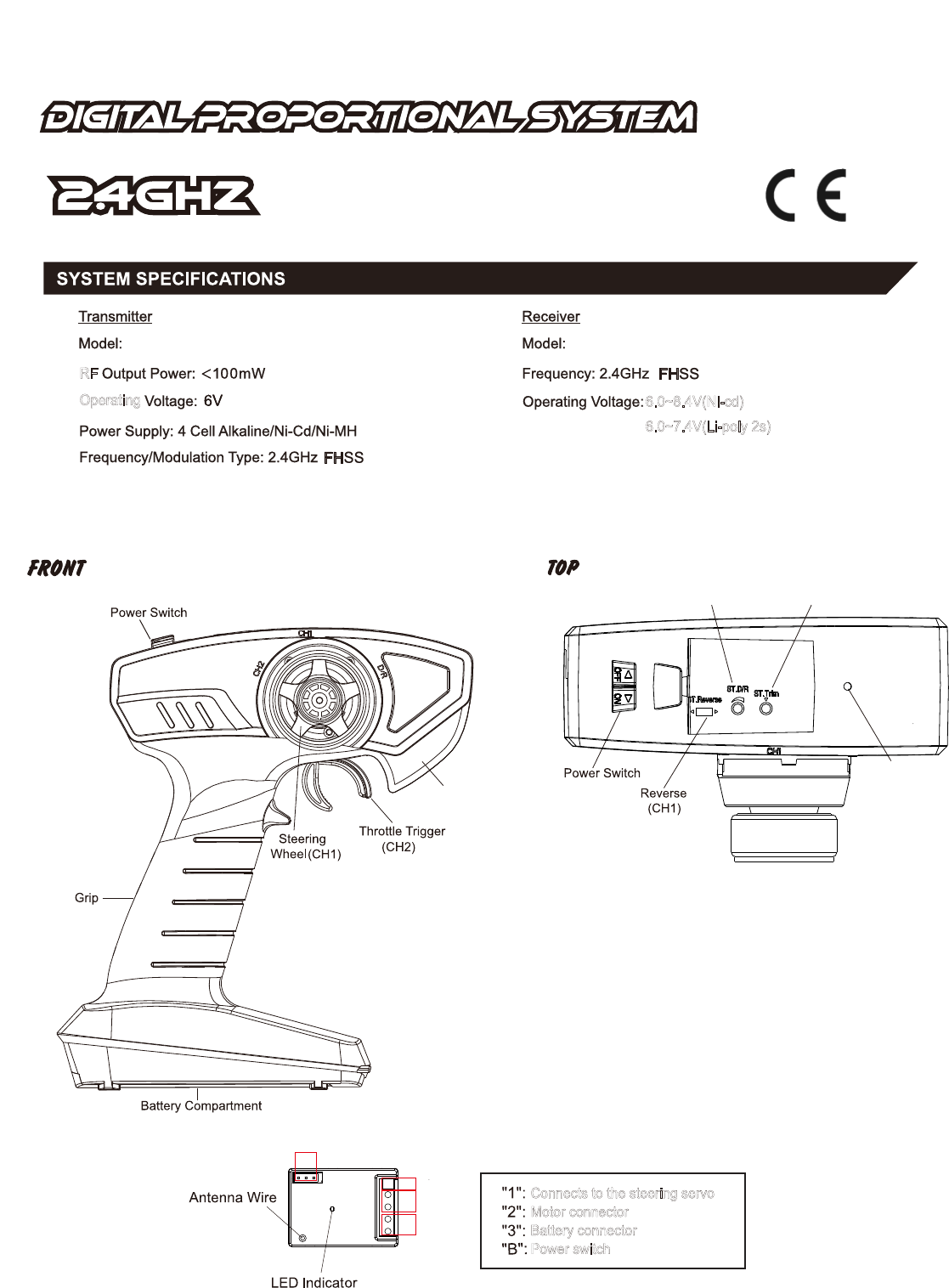
Connects to the steering servo
Motor connector
Battery connector
Power switch
CONNECTION
MT-201
Operating
RF
6.0~8.4V(Ni-cd)
6.0~7.4V(Li-poly 2s)
MT-201RE
MT-201
Antenna (Built in)
Steering Dual Rate
Lever (D/R)
Steering Trim
Lerer (CH1)
Working Station
Indicator
SHENZHEN EXPORTPRO TECHNOLOGY CO.,LTD
Operating temperature:-20 to 55
2nd Floor,99 Industrial Centre, Western Industrial Park, Shajing Town, Bao’an District, Shenzhen City, Guangdong Province, People's Republic of China
°C
Operating temperature:-20 to 55°C
Operating temperature:-20 to 55°C
Operating temperature:-20 to 55°C
Operating temperature:-20 to 55°C
Operating temperature:-20 to 55°C
Operating temperature:-20 to 55°C
Operating temperature:-20 to 55°C
Operating temperature:-20 to 55°C
Operating temperature:-20 to 55°C
Operating temperature:-20 to 55°C
Operating temperature:-20 to 55°C
SHENZHEN EXPORTPRO TECHNOLOGY CO.,LTD
2nd Floor,99 Industrial Centre, Western Industrial Park, Shajing Town, Bao’an District, Shenzhen City, Guangdong Province, People's Republic of China
SHENZHEN EXPORTPRO TECHNOLOGY CO.,LTD
2nd Floor,99 Industrial Centre, Western Industrial Park, Shajing Town, Bao’an District, Shenzhen City, Guangdong Province, People's Republic of China

02
MT-201
:
1.CH1(Steering) Trim:
Steering neutral adjustments can be made by moving the knob to the left or right.
When you install a servo, always check whether the servo is at its neutral position. Adjust the servo horn position
to be parallel to the linkage. Be sure the knob on the transmitter is at the neutral position.
2.CH1(Steering Dual-Rate)D/R:
Use this function to adjust the steering travel of your model. If the model understeers while cornering, add steering by
turn the D/R knob in a CW direction. When the model oversteers, take away steering by turning the D/R konb in a CCW
direction.
3.CH1(Steering)Reverse:
If the servo operate is in the opposite direction,pull the reverse lever
for the servo reversing.
4.Low Battery Indicator:
If the transmitter battery voltage drops below 4.2V, the LED will flash.And please replace the battery for proper operation.
MT-201RE:Receiver+ESC
1.CH1(Steering)Output:Connect the servo for steering operation, do not reverse in order not to cause damage
2.Battery connector: Connects to the battery.Red is Positive +,Black is Negative -. For Ni-cd battery 5~
(6.0
7cells
~8.4V) or Lithium-Poly battery 2S(7.4V)
3.Motor connector:Connect to the motor.
4.CH2(Throttle) Operation:Forward, reverse and brake are all linear.
When switched to reverse operation just returning the throttle trigger from the brake position to the neutral position.
5.Low-voltage/overheating protection: When the battery's voltage is under 5.5V, the car speed will slow down until it stops.
The LED indicator starts to flash, the battery on the car needs to be charged. When the receiver is over-heated, the motor
will stop working and the car will stop. In order not to burn the motor,do not re-start the car.
:
MT-201&MT-201RE Bind :
Binding Process
1.Turn the transmitter power on while pressing the bind sw(Do not mix alkaline batteries, standard(carbon-zinc)
or rechargeable(Nickel-Cadmium) batteries).
2.The transmitter Red LED will flash.
4.Once the binding process is completed, the receiver and the transmitter will bind automatically if turn on the transmitter
again. If turning the receiver on again, it is in the binding mode, please follow step 2 and step 3 to complete the binding
procedure.
3.It is in the binding process after turning on the transmitter in 2 seconds, the transmitter and the receiver will start the
process of binding.When the LED indicator on the reciever continuesly lit, it shows the binding process is sucessful.
(Do not keep the reciever far away from the transmitter when binding.) If not,turn on/off the receiver and try again or
shorten the binding distance.
MT-201 LED Display
LED ON:
:
Power on
Power off
LED Rapid Flash:Steering wheel and the throttle trigger are not at their netutral position, please re-adjust the position
and then turn on the transmitter once again
LED Slow Flash
LED OFF
:Power offLED OFF
:
LED Rapid Flash:
LED Slow Flash:
low-voltage warning
low-voltage warning
MT-201RE LED Display
LED ON:In the connecting mode
The singal is interrupted
FCC STATEMENT
This device complies with Part 15 of the FCC rules. Operation is subject to the following two
conditions: 1) this device may not cause harmful interference, and 2) this device must accept any
interference received, including interference that may cause undesired operation.
Changes or modifications not expressly approved by the party responsible for compliance could
void your authority to operate the equipment.
NOTE: This equipment has been tested and found to comply with the limits for a Class B digital
device, pursuant to Part 15 of the FCC Rules. These limits are designed to provide reasonable
protection against harmful interference in a residential installation.
This equipment generates uses and can radiate radio frequency energy and, if not installed and
used in accordance with the instructions, may cause harmful interference to radio communications.
However, there is no guarantee that interference will not occur in a particular installation. If this
equipment does cause harmful interference to radio or television reception, which can be
determined by turning the equipment off and on, the user is encouraged to try to correct the
interference by one or more of the following measures:
Reorient or relocate the receiving antenna.
Increase the separation between the equipment and receiver.
Connect the equipment into an outlet on a circuit different from that to which the receiver is
connected.
Consult the dealer or an experienced radio/TV technician for help.
03