EZ Automation EAS CAP/EAS Encoder-Decoder User Manual EZ EAS Manual
EZ Automation CAP/EAS Encoder-Decoder EZ EAS Manual
Draft Copy of User Manual

FCC Part 15 Notice:
Note: This equipment has been tested and found to comply with the limits for a Class B digital device,
pursuant to part 15 of the FCC Rules. These limits are designed to provide reasonable protection against
harmful interference in a residential installation. This equipment generates, uses and can radiate radio
frequency energy and, if not installed and used in accordance with the instructions, may cause harmful
interference to radio communications. However, there is no guarantee that interference will not occur in a
particular installation. If this equipment does cause harmful interference to radio or television reception,
which can be determined by turning the equipment off and on, the user is encouraged to try to correct the
interference by one or more of the following measures:
—Reorient or relocate the receiving antenna.
—Increase the separation between the equipment and receiver.
—Connect the equipment into an outlet on a circuit different from that to which the receiver is connected.
—Consult the dealer or an experienced radio/TV technician for help.
Special Instructions:
Shielded interconnect cables and a shielded AC power cable must be employed with this equipment to
ensure compliance with the pertinent RF emission limits governing this device. Changes or modifications
not expressly approved by the system’s manufacturer could void the user’s authority to operate the
equipment.
Assembled From Tested Components by:
EZ Automation
3302 N. Van Dyke Rd.
Imlay City, MI 48444
(810) 895-2040
www.voicetracking.com
Product Name EZ Automation
Product Model EAS
EZ Automation EAS/CAP Encoder Decoder
www.voicetracking.com
(810) 895-2040
© 2005-2012
GETTING STARTED PROGRAMMING:
OVERVIEW: This section will take you step by step through the
programming setup process to get your EAS system programmed and
running. This initial setup should be performed by or at least with the
assistance of your Engineering department. It is important that the initial
programming is done properly.
PART 1: SYSTEM SETUP.
STEP 1: GETTING TO THE STATION SETUP SCREEN. The first step is
configuring the EAS unit. To enter the setup, go to the menu bar click on
Config, then on Station Setup. This will take you to the station setup screen.
.

STEP 2: Identifier. Enter the station callsign in the upper left field. This
must be 8 characters long. Fill any unused spaces with slashes "/" (required).
STEP 3: Input Alias(s). Fill in the sources name you are receiving on the
analog inputs. This step is optional but is recommended.
STEP 4: Message Timeout. This is the recording timeout in seconds for
received EAS messages (required). 120 seconds is typical.
STEP 5: UTC Comp. This is the difference between universal time and your
time zone in hours (required).
STEP 6: Home FIPS. This is your home county (required). This the state
code plus county code. Example: Say a station is licensed to New York, New
York….New York's state code is 36. New York's county code is 061. So the
code is 0+36+061 or 036061. A list of FIPS codes is available at this
website: http://www.epa.gov/enviro/html/codes/state.html
You may also obtain your county code from PART 2 on the next page.
STEP 7: EAS Originator Code. This is a three-letter code assigned to the
type of facility (required). A broadcast station would use EAS. The National
Weather service uses NWS. Other government agencies use CIV.
STEP 8: 2-Tone Length. This is the length in seconds of the two-tone
attention signal (850Hz and 953 Hz) transmitted during alerts. At the time of
this writing, 8 seconds is required.
PART 2: COUNTY SETUP.
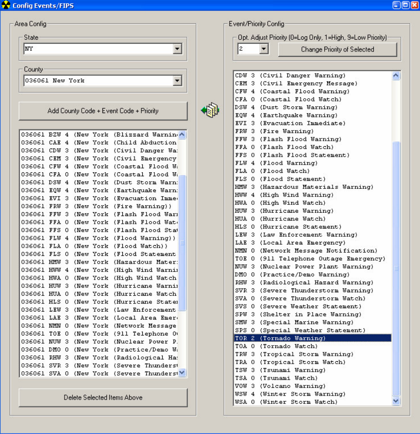
STEP 1: GETTING TO THE EVENT/FIPS SETUP SCREEN. This is the
second part is configuring the EAS unit. To enter the setup, go to the menu
bar click on Config, then on Event/FIPS Setup. This will take you to the
setup screen (see picture below).
You will first want to adjust the priority of the Event Codes (optional). This is
done on the right-hand pane. Click on the item(s) you want to adjust so it is
highlighted in blue, select the Priority from the drop-down, and then press
Change Priority of Selected. For example in most areas, a Tornado
Warning would be second-highest priority after a national level emergency
(EAN) which is a 1 priority. We suggest setting TOR (Tornado Warning) to a
priority of 2. A priority of 0 means no automatic action will be taken, but it will
be logged.
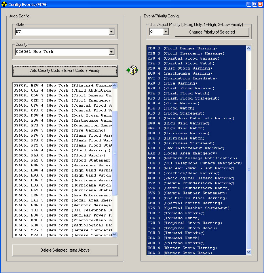
STEP 2: Adding Counties to Event Codes. In this step you must highlight
the Event/Priority codes on the right that you want your system to respond to
(you may hold CTRL key to select multiple one, and/or you may drag to
select all of them. Next, on the upper left, select a State and then select a
County in your coverage area. Lastly, press the Add County Code + Event
Code + Priority button to add them to the list on the lower left (see picture
below). You will need to change the county and press the Add button for all
counties in your service area.
Congratulations! You have completed the software setup part of the
instructions. Your system is almost ready to be put into operation.
Audio Wiring:
Note: Static Sensitivity: Some of the devices contained in unit are susceptible
to static discharges. Appropriate static control procedures should be employed
at all times when servicing. All devices connected to the unit should be
grounded. For example, a properly grounded three-prong outlet is probably
acceptable. In the event that the device does not have a proper grounding plug,
a #12 or #14 stranded grounding wire should be added to the device in a “star”
configuration. Many stations neglect to connect their satellite receivers, dishes,
cable modems, DSL lines and etc to a common ground system. Because of the
potential for lightning damage, all of the devices really need to be connected to a
“star-type” common ground. In addition, a UPS with power, telephone, antenna,
and Ethernet protection is strongly urged.
Installation: The basic components of installation are the Audio Inputs, and the
audio output. The unit should be wired with #18-22 gauge stranded audio wire
such as a Belden 8451 or 8723 or equivalent.
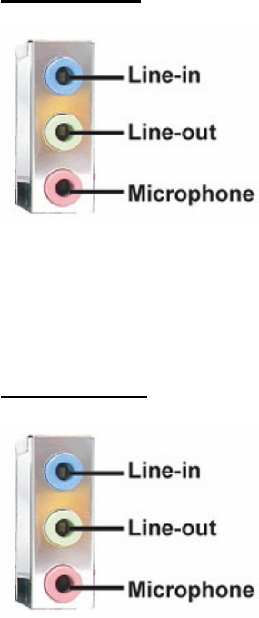
Audio inputs:
The Line In is unbalanced line-level inputs. The inputs should be taken directly
from the audio output source from each device. The left input audio is input #1
(tip), and the right input (ring) is input #2. An optional 3rd/4th input is available on
front panel.
Audio Output:
The Line Out is low impedance (approximately 600 Ohms). The output should
be connected directly in the main audio path (IE before the audio processor)
through an audio switch.
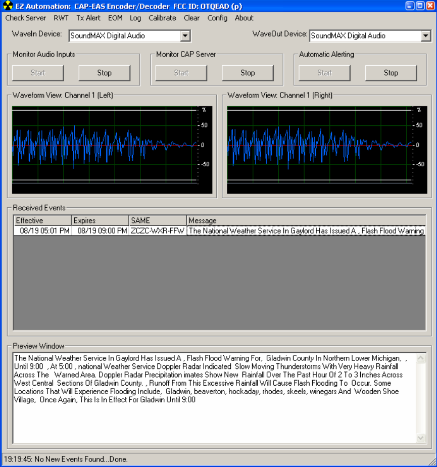
Setting Input Audio Levels:
All receivers should be adjusted so loudest signal peaks just occasionally
reach the bottom white line segments in the Waveform View window.
Remember the Left channel is 1st audio input, and the Right channel is audio
2nd audio input. Note: The audio card's audio input can be adjusted if
receiver has insufficient level adjustment, but we suggest adjusting the
receiver audio level first. You can also monitor the receiver audio via the
internal speakers:
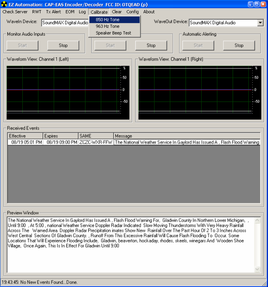
Setting Output Audio Levels:
You may test and set the audio output levels by clicking on menu then on
Calibrate and then either 853Hz or 960 Hz tone button. This will allow the
adjustment of audio levels in the broadcast facility produce at least 40%
modulation as required by FCC rules at the time of writing.
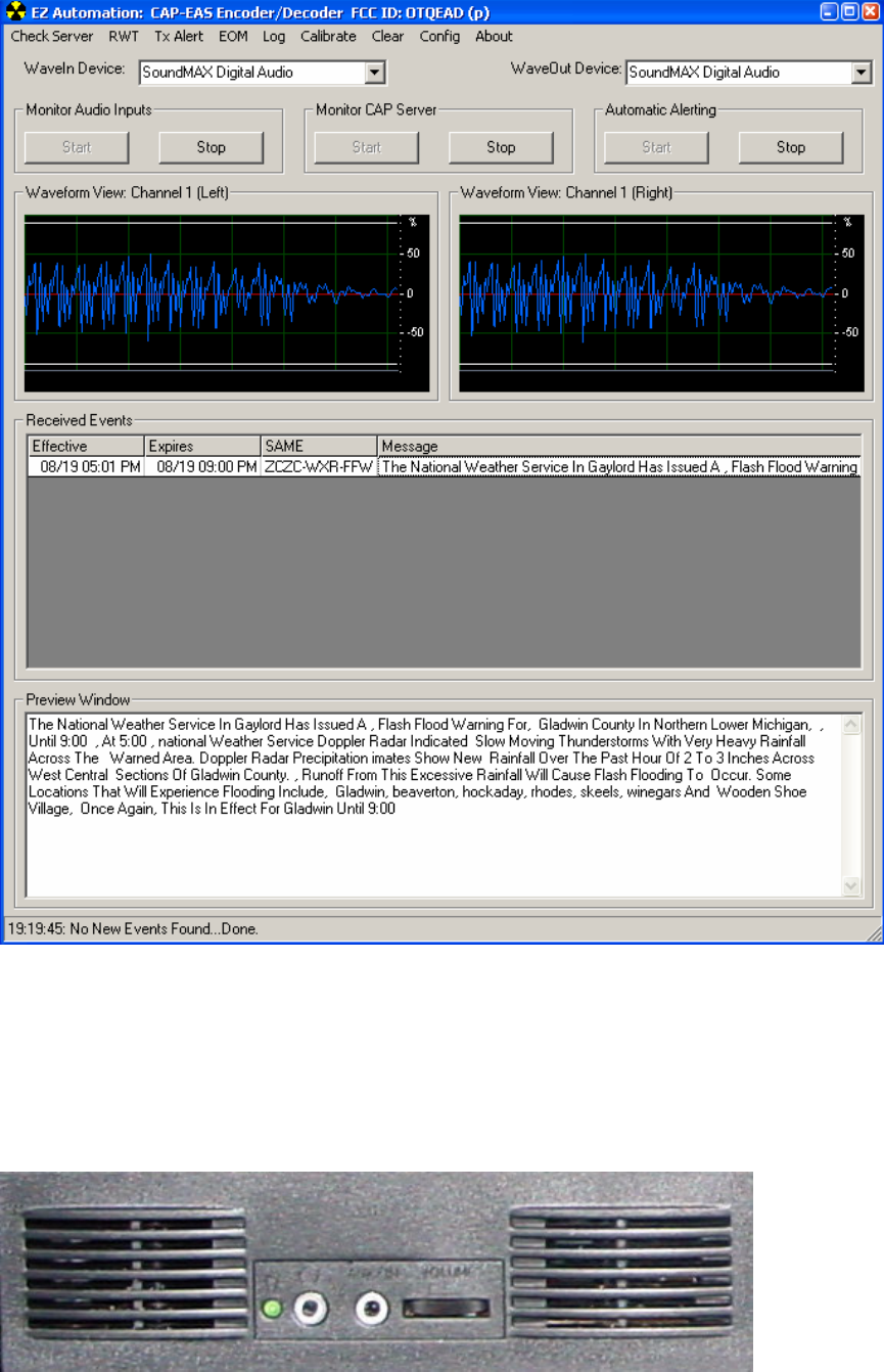
Main Screen Overview
The main screen is straightforward in its operation.
The Monitor Audio Input button is used for starting/stopping the monitoring
of the external receivers.
The Monitor CAP Server button is used for starting/stopping the monitoring
of the IPAWS server.
The Automatic Alerting button is used for starting/stopping the automatic
transmission of EAS alerts not already in progress (queued alerts can still be
sent manually by clicking on Tx Alerts button).
Menu System:
The menu bar has other features:
Send, Build Header is used to create a new custom header.
Send, RWT is used to send a Required Weekly Test.
Send, Send Qued Alert is used to send a queued alert when in manual
mode (automatic alerting is off).
Send, EOM is used to send another End of Message signal in situations
where an interruption of your broadcast signal (IE momentary power outage)
has caused down-stream stations not to receive the EOM signal, which may
cause those stations to get stuck rebroadcasting your facility.
Log is used to display both receive and transmit logs.
Check Server polls the IPAWS server for any updates. This may be useful
in severe weather situations to acquire an alert quicker after another source
has already alerted you to an active alert.
Clear is used to clear the Received Events and Preview Window on main
screen. This may be useful to clear items that have been processed to make
it visually easier to see when new events arrive.
Calibrate is used to calibrate system levels (see page 6).
Config is used to access configuration screens to setup software (see pages
1 to 4).
About is used to see the version number and copyright notices.
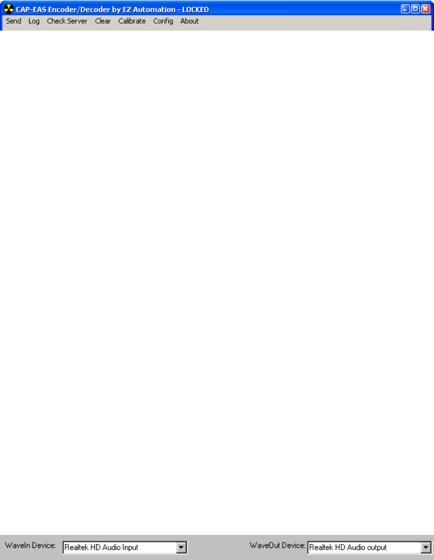
Wave Inputs/Outputs:
Used for configuration of audio device inputs and outputs. Select the
designated audio device.
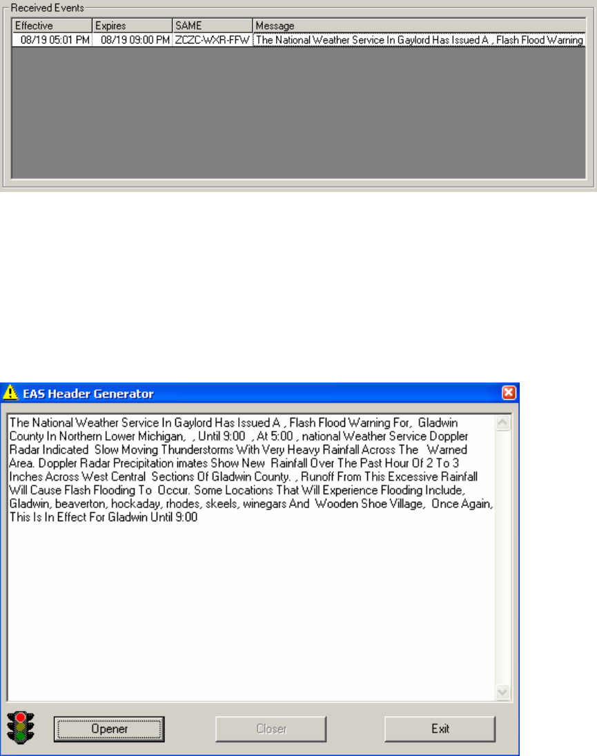
Received Events:
This area of the screen displays any received messages, either from the
analog inputs or the IPAWS server. Received alerts may be sorted in each
column by clicking on the column heading.
Clicking on row will display full message in the Preview Window.
Double-clicking on a row will launch the EAS Header form, for manually
transmitting an alert with a voiceover announced by local personnel:
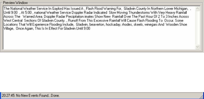
Preview Window:
This window shows more detailed information about messages, alerts being
transmitted/received or any errors (such as lost internet connection).
Status Bar:
The status bar at the bottom of window shows you what the system is doing
at the present time (or the last thing it did). In the example above the status
bar shows the system did a check of the IPAWS server and that No New
Events were found. The status bar will also show if there is an internet
connection issue, and if any alerts are being received or transmitted. Any
errors will also be displayed in the Preview Window.

Troubleshooting (Always try a reboot before contacting us for a problem not on this list):
Q: "Invalid Wave Device" error is caused by missing, defective, or recently
deleted sound card configurations. Check Control Panel for audio device
configurations.
Q: Slow operation, or stuttering audio symptoms.
A: This is typically caused by wayward programs, a virus (CPU usage at 100%)
or improper driver, or other hardware failure such as a bad drive. Hit CTRL-ALT-
DEL and check the list of program to see which ones are consuming resources,
also try a reboot of system.
Q: When closing program or after a power failure, it does not start exactly where
it left off.
A: We recommend the unit be left on 24/7/365 and a high quality UPS that can
power the unit for at least 30 minutes hour be installed.
Q: My time keeps drifting or jumping, how do I fix it?
A: You should supply a stable Internet connection with high throughput and low
latency. Double-click on the clock in the lower right hand corner. Check to make
sure time zone is correct and daylight saving enabled (provided you’re up to date
on software patches). Under Internet Time tab check "automatically sync with an
Internet time server". Press the "update now" to see if time will sync. If the sync
works properly but you'd like to have it update more often then follow instructions
on this webpage: http://www.helpwithwindows.com/WindowsXP/tune-17.html
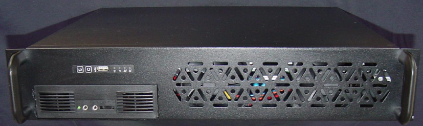
Specifications:
Cooling Fan: 2 x 80mm ball bearing fans
Indicator: Power ON/OFF x 1, HDD x 1, RX/TX
Connectors: One front USB port, four rear USB, two serial, one parallel, Ethernet, and two PS/2.
Dimensions ( W x D x H ): 16.9" x 15.25" x 3.5" (430mm x 387.3mm x 88mm)
Environment Temperature: 0/50 °C, 32/122 °F (Operating) -20/60 °C, -4/140 °F (Non-Operating)
Relative Humidity: to 95%, non-condensing
Vibration ( 5-500 Hz ): 0.5 Grms (Operating), 2 G (Non-Operating)
Power: 115 VAC, switchable to 230 VAC (-87%/+115% Tolerance)
FCC Part 15 Notice:
Note: This equipment has been tested and found to comply with the limits for a Class B digital device,
pursuant to part 15 of the FCC Rules. These limits are designed to provide reasonable protection against
harmful interference in a residential installation. This equipment generates, uses and can radiate radio
frequency energy and, if not installed and used in accordance with the instructions, may cause harmful
interference to radio communications. However, there is no guarantee that interference will not occur in a
particular installation. If this equipment does cause harmful interference to radio or television reception,
which can be determined by turning the equipment off and on, the user is encouraged to try to correct the
interference by one or more of the following measures:
—Reorient or relocate the receiving antenna.
—Increase the separation between the equipment and receiver.
—Connect the equipment into an outlet on a circuit different from that to which the receiver is connected.
—Consult the dealer or an experienced radio/TV technician for help.
Special Instructions:
Shielded interconnect cables and a shielded AC power cable must be employed with this equipment to
ensure compliance with the pertinent RF emission limits governing this device. Changes or modifications
not expressly approved by the system’s manufacturer could void the user’s authority to operate the
equipment.
Assembled From Tested Components by: EZ Automation; 3302 N. Van Dyke Imlay City, MI
48444; (810) 895-2040
Product Name EZ Automation
Product Model EAS
EZ Automation Warranty Agreement
EZ Automation (Manufacturer) warrants that this product is free of defects in both materials and
workmanship. Should any part of this equipment be defective, Manufacturer agrees, as its option, to:
A. Repair or replace any defective part free of charge (except transportation charges) for a period
of 11 Months from the date of original purchase, provided the owner returns the equipment to Manufacturer
at the address set forth below. No charge will be made for parts or labor during this period.
B. Furnish replacement for any defective parts in the equipment for a period of 11 Months from the
date of original purchase. Replacement parts shall be furnished without charge except labor and
transportation.
This Warranty excludes assembled products not manufactured by Manufacturer whether or not
they are incorporated in a Manufacturer product or sold under a Manufacturer part or Model number.
THIS WARRANTY IS VOID IF:
A. The equipment has been damaged by negligence, accident, fire, lightening, act-of-nature or
mishandling, or has not been operated in accordance with the procedures described in the operating and
technical instructions: or
B. The equipment has been altered or repaired by other than Manufacturer or authorized service
representative or Manufacturer; or
C. Adaptations or accessories other than those manufactured or provided by manufacturer have
been made or attached to the equipment which, in the determination of Manufacturer, shall have affected
the performance, safety, or reliability of the equipment; or,
D. The equipment’s original serial number has been modified or removed.
NO OTHER WARRANTY EXPRESS OR IMPLIED, INCLUDING WARRANTY OF
MERCHANTABILITY OR FITNESS FOR ANY PARTICULAR USE, APPLIES TO THE EQUIPMENT, nor is
any person or company authorized to assume any warranty for Manufacturer or any other liability in
connection with the sale of Manufacturer products.
Manufacturer does not assume any responsibility for consequential damages, expenses or loss of
revenue or property, inconvenience or interruption in operation experience by the customer due to a
malfunction in the purchased equipment. No warranty service performed on any product shall extend the
applicable warranty period.
In case of unsatisfactory operation, the purchaser shall promptly notify Manufacturer at the
address set forth below in writing, giving full particulars as to the defects or unsatisfactory operation. Upon
receipt of such notice, Manufacturer will give instructions respecting the shipment of the equipment, or such
other matters as it elects to honor this warranty as above provided. This warranty does not cover damage
to the equipment during shipping and Manufacturer assumes no responsibility for such damage. Customer
shall pay all shipping costs.
This warranty extends only to the original purchaser and is not assignable or transferable.
EZ Automation
3302 N. Van Dyke
Imlay City, MI 48444
(810) 895-2040
www.voicetracking.com