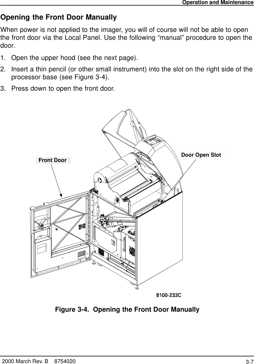
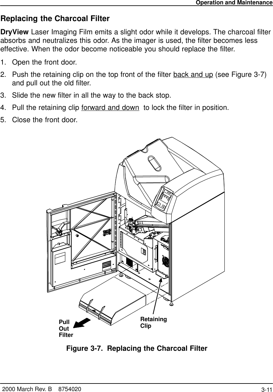
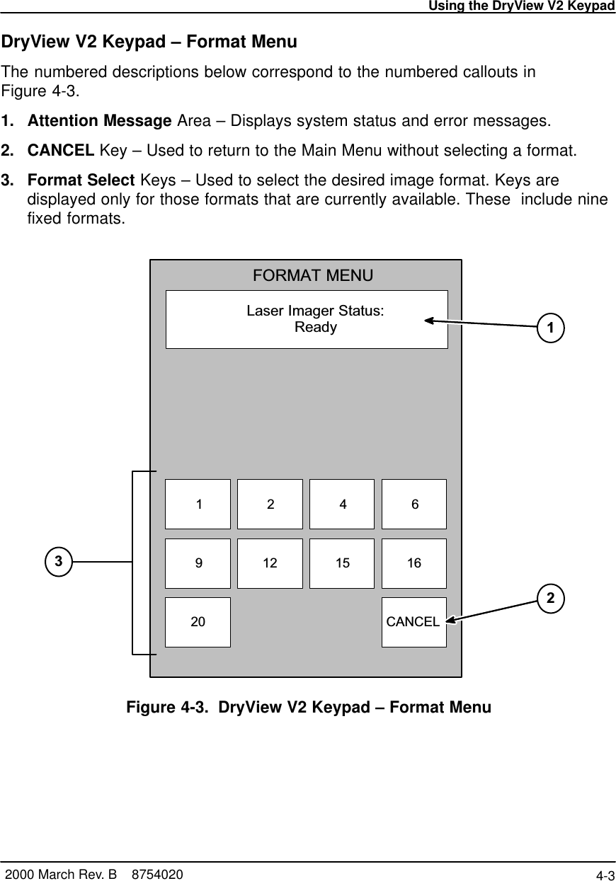
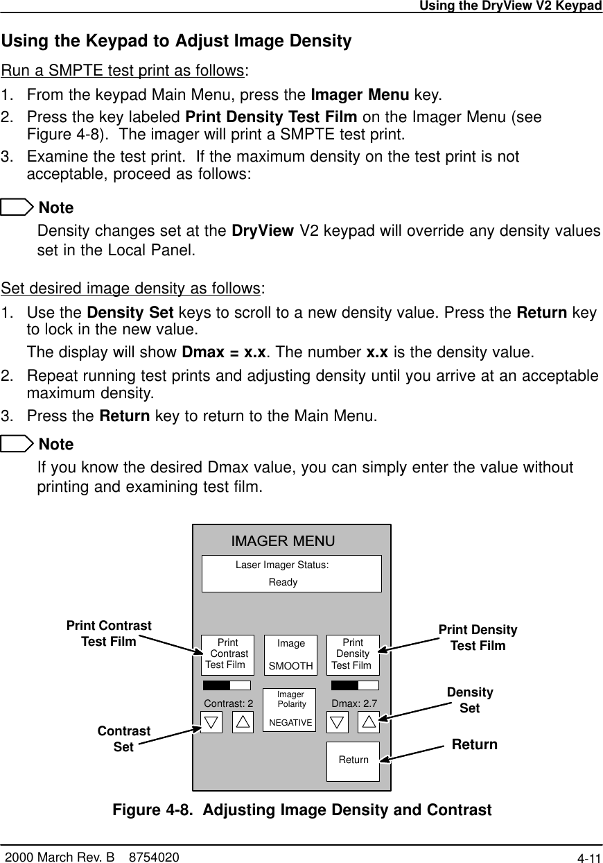
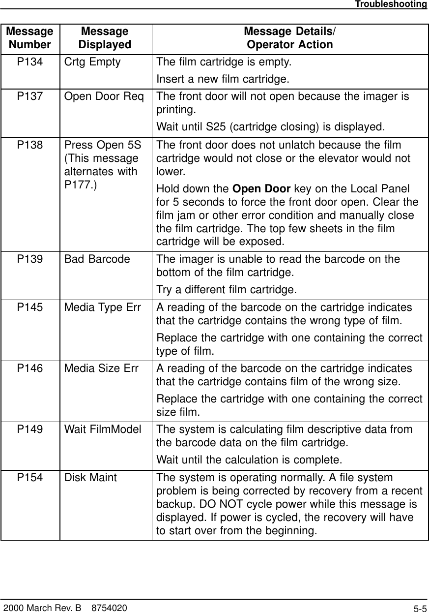
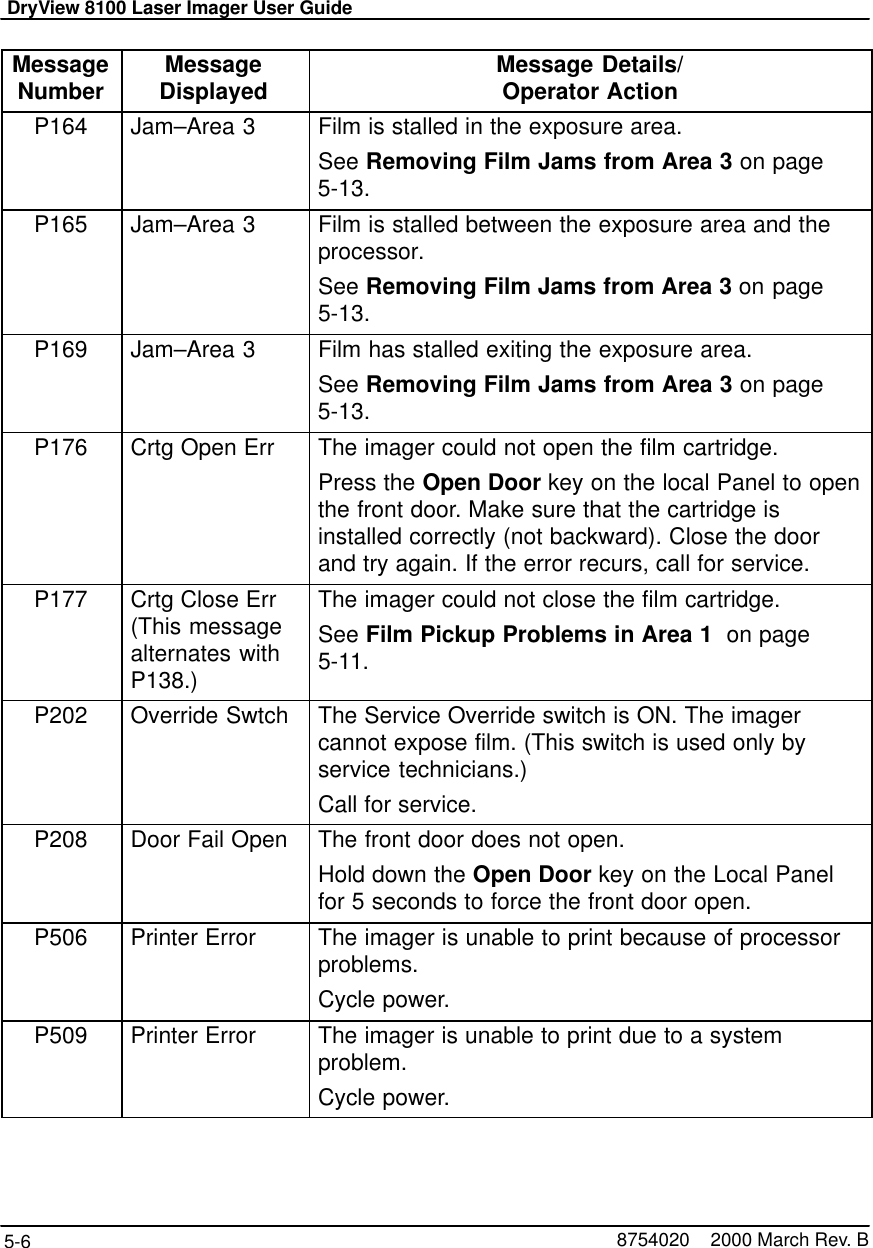
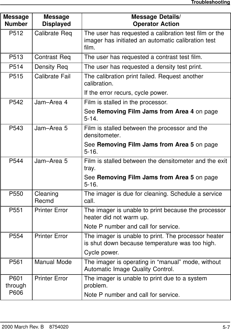
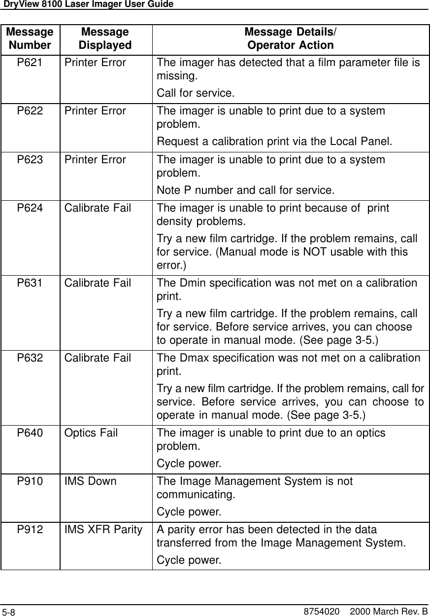
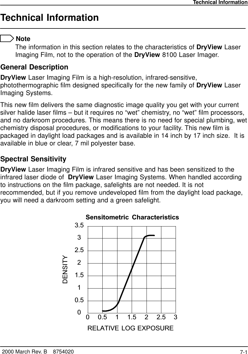
Eastman Kodak 810082007E2537 Medical Laser Imager User Manual 8100

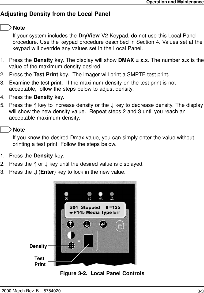
Eastman Kodak Company Medical Laser Imager 8100

Contents

8100

7 X 9 inside coverUser GuideKodak DryView 8100 Laser Imager875402096-0000-0197-23/00 Rev. B
Safety, EMC, and CE Marking Compliancei2000 March Rev. B    8754020Safety, EMC, and CE Marking ComplianceRead and understand all instructions before using.For a translation of the following warnings, please refer to the applicable safetyaddendum listed below:DryView 8100 Imager User Guide Safety Addendum (Polish) 74-0500-5507-3DryView 8100 Imager User Guide Safety Addendum (Hebrew) 74-0500-5508-1DryView 8100 Imager User Guide Safety Addendum (Korean) 74-0500-5509-9!WARNING  This equipment is operated with hazardous voltage which can shock,burn, or cause death.Remove wall plug before servicing equipment. Never pull on cord to remove fromoutlet. Grasp plug and pull to disconnect.Do not operate equipment with a damaged power cord.Do not use an extension cord to power this equipment.Use only the power cord supplied with this equipment.Position the power cord so it will not be tripped over or pulled.Connect this equipment to a grounded outlet.!WARNINGThis equipment contains moving parts that may be accessible to the user. Looseclothing, jewelry, or long hair may cause minor personal injury or damage to theequipment. Do not operate equipment with the covers open. Do not operateequipment with any of the safety interlocks overridden.!WARNINGThis equipment is not contained in a sealed cabinet. Therefore it must not be used inlocations where it can come in contact with liquids, including bodily fluids.!WARNINGFor continued protection against fire, replace fuses only with fuses of the same typeand rating.
DryView 8100 Laser Imager User Guideii   8754020  2000 March Rev.BRead and understand all instructions before using.!CAUTION  Do not use in the presence of flammable anesthetics, oxygen or nitrous oxide. Thisequipment does not have a gas sealed electronics enclosure and could ignite anyflammable or explosive gases present in its environment.!CAUTIONThis equipment is intended to connect to other medical devices. Installation andservice maintenance are to be performed only by qualified service personnel. Thelaser in the equipment is not a patient device. Therefore the equipment must beinstalled no closer than 1.83 meters from a patient bed or chair.!CAUTIONDo not substitute or modify any part of this equipment without approval of EastmanKodak Company.!CAUTIONThis equipment has been tested and found to comply with the limits for a Class Bdigital device, pursuant to part 15 of the FCC rules. Those limits are designed toprovide reasonable protection against harmful interference in a residentialinstallation. This equipment generates, uses, and can radiate radio frequencyenergy and, if not installed and used in accordance with the instructions, may causeharmful interference to radio communications. However, there is no guarantee thatinterference will not occur in a particular installation. If this equipment does causeharmful interference to radio or television reception, which can be determined byturning the equipment off and on, the user is encouraged to try to correct theinterference by one or more of the following measures:Reorient or relocate the receiving antenna.Increase the separation between the equipment and the receiver.Connect the equipment into an outlet on a circuit different from that to which thereceiver is connected.Consult the dealer or an experienced radio/TV technician for help.
Safety, EMC, and CE Marking Complianceiii2000 March Rev. B    8754020Read and understand all instructions before using.!CAUTIONGeneral External Cleaning: This equipment may be cleaned with a damp clothusing water with mild detergent, or commercial electronic equipment cleaner.8100–38L
DryView 8100 Laser Imager User Guideiv   8754020  2000 March Rev.BRead and understand all instructions before using. !DANGER    The equipment employs a 50 milliwatt laser. Laser radiation may be present whenthe machine operates without the rear cover installed.Use of controls or adjustments, or performance of procedures other than thosespecified herein, may result in eye damage.The rear cover shall be removed by authorized service personnel only.6E7000 Rev. AClass 1 LaserLaser de catégorie 1Laser-Klasse 1Laser di Classe 1Klass 1 LaserBypassing interlocks (other than the Service Interlock above)will allow the system to run with the laser energized.Exposure to laser light may result in permanent eye damage.DANGER
Safety, EMC, and CE Marking Compliancev2000 March Rev. B    8754020Read and understand all instructions before using.
DryView 8100 Laser Imager User Guidevi   8754020  2000 March Rev.BThis equipment has been tested for and complies with the following Safety andEmission Standards. Certificates of Compliance and Declarations of Conformityhave been issued as shown below.Safety:Canada:C22.2 NO 950-95–CAN/CSA  Safety for Information Technology Equipment,Including Electrical Business EquipmentC22.2 NO 601.1–M90–CAN/CSA  Medical Electrical Equipment – Part 1:General Requirements for SafetyEurope:EN60950: Safety of Information Technology Equipment, Including ElectricalBusiness Equipment (IEC 60950 : 1991, Modified) (Includes Amendment A1 andA2: 1993)EN60601–1–1: Medical electrical equipment – Part 1: General requirements forsafety – Section 1: Collateral standard: Safety requirements for medical electricalsystemsEN60825–1: Safety of laser products – Part 1: Equipment classification,requirements and user’s guideU.S.A.:UL 1950: Safety of Information Technology Equipment, Including ElectricalBusiness Equipment DOD (Bi–National Standard) with UL 2601–1 MedicalElectrical Equipment, Part 1: General Requirements for Safety21CFR1040.10 Class I: FDA CDRH Code of Federal Regulations Title 21,Volume 8, Food and Drugs,  Part 1040 Performance Standards ForLight–Emitting Products, Section 10 Laser ProductsFDA Premarket Notification 510(K): Regulatory Requirements For MedicalDevicesRest of World:IEC 950: Safety of information technology equipmentIEC 60601–1–1: Medical electrical equipment – Part 1: General requirements forsafety – Section 1: Collateral standard: Safety requirements for medical electricalsystemsIEC 60825–1: Safety of laser products – Part 1: Equipment classification,requirements and user’s guide
Safety, EMC, and CE Marking Compliancevii2000 March Rev. B    8754020EMC:Canada:CAN/CSA–C108.6–M91  Class A: Limits and Methods of Measurement ofElectromagnetic Disturbance Characteristics of Industrial, Scientific and Medical(ISM) Radio–Frequency EquipmentEurope:EN55022 (CISPR 22)  Class B Group 1: Limits and Methods of Measurement ofRadio Interference Characteristics of Information Technology EquipmentEN61000–3–2 (IEC 1000–3–2): Electromagnetic compatibility (EMC) – Part 3:Limits – Section 2: Limits for harmonic current emissions (equipment inputcurrent <= 16 per phase)EN 61000–4–2 (IEC 1000–4–2): Electromagnetic compatibility (EMC) – Part 4:Testing and measurement techniques – Section 2: Electrostatic dischargeimmunity test. Basic EMC PublicationEN 61000–4–3 (IEC 1000–4–3): Electromagnetic compatibility (EMC) – Part 4:Testing and measurement techniques – Section 3: Radiated, radio–frequency,electromagnetic field immunity testEN 61000–4–4 (IEC 1000–4–4): Electromagnetic compatibility (EMC) – Part 4:Testing and measurement techniques – Section 4: Electrical fast transient/burstimmunity test. Basic EMC PublicationEN 61000–4–5 (IEC 1000–4–5): Electromagnetic compatibility (EMC) – Part 4:Testing and measurement techniques – Section 5: Surge immunity testEN 61000–4–6 (IEC 1000–4–6): Electromagnetic compatibility (EMC) – Part 4:Testing and measurement techniques – Section 6: Immunity to conducteddisturbances, induced by radio–frequency fieldsEN 61000–4–11 (IEC 1000–4–11): Electromagnetic compatibility (EMC) – Part 4:Testing and measuring techniques – Section 11: Voltage dips, short interruptionsand voltage variations immunity testsU.S.A.:FCC Rules and Regulations, Title 47, Part 15,  Subpart B, Class B: Radiofrequency devices: Unintentional RadiatorsRest of World:CISPR 22 Class B Group 1: Limits and Methods of Measurement of RadioInterference Characteristics of Information Technology Equipment
DryView 8100 Laser Imager User Guideviii   8754020  2000 March Rev.BEU Directives:73/23/EEC  Council Directive on the Harmonization of the Laws of MemberStates Relating to Electrical Equipment Designed for Use within Certain VoltageLimits89/336/EEC  Council Directive on the Approximation of the Laws of the MemberStates Relating to Electromagnetic Compatibility93/42/EEC  Council Directive Concerning Medical DevicesCE Marking:Documents concerning the conformance of this product to Council Directive93/42/EEC of 14 June 1993 concerning Medical Devices can be obtained from theEastman Kodak Health Imaging Systems European Representative at:Kodak AGQuality ServicesProduct Safety70323 StuttgartGermanyPhone: ++49 711 406 2993Fax: ++49 711 406 3513DOC:This Class A digital apparatus meets all requirements of the CanadianInterference-Causing Equipment Regulations.Cet appareil numérique de la Classe A respecte toutes les exigences du Règlementsur le matérial brouilleur du Canada.
Table of Contentsix2000 March Rev. B    8754020PLEASE NOTE The information contained herein is based on the experienceand knowledge relating to the subject matter gained by EastmanKodak Company prior to publication.No patent license is granted by this information.Eastman Kodak Company reserves the right to change thisinformation without notice and makes no warranty, express orimplied, with respect to this information. Kodak shall not be liablefor any loss or damage, including consequential or specialdamages, resulting from the use of this information, even if lossor damage is caused by Kodak’s negligence or other fault.Table of ContentsDescription PageSafety, EMC, and CE Marking Compliance i. . . . . . . . . . . . Introduction 1-1. . . . . . . . . . . . . . . . . . . . . . . . . . . . . . . . . . . . . . . . Introducing the Kodak DryView 8100 Laser Imager 1-1. . . System Configurations 1-2. . . . . . . . . . . . . . . . . . . . . . . . . . . . DryView 8100 Laser Imager 1-2. . . . . . . . . . . . . . . . . . . . Dryview 8100 PACS Link Laser Imager 1-2. . . . . . . . . . Keypad Features 1-3. . . . . . . . . . . . . . . . . . . . . . . . . . . . . . . . . How the DryView 8100 Laser Imager Works 1-4. . . . . . . . . Automatic Image Quality Control 1-4. . . . . . . . . . . . . . . . . . . Manual Mode of Operation 1-4. . . . . . . . . . . . . . . . . . . . . . . . . How This Manual is Organized 1-6. . . . . . . . . . . . . . . . . . . . . Controls and Indicators 2-1. . . . . . . . . . . . . . . . . . . . . . . . . . . . . Main Cabinet Controls and Indicators 2-1. . . . . . . . . . . . . . . Local Panel Functions 2-2. . . . . . . . . . . . . . . . . . . . . . . . . . . . . Operation and Maintenance 3-1. . . . . . . . . . . . . . . . . . . . . . . . . System Power Up 3-1. . . . . . . . . . . . . . . . . . . . . . . . . . . . . . . . Methods for Acquiring and Printing Images 3-2. . . . . . . . . . Methods for Adjusting Image Density and Contrast 3-2. . . Adjusting Density from the Local Panel 3-3. . . . . . . . . . . . . . Adjusting Contrast from the Local Panel 3-4. . . . . . . . . . . . .
DryView 8100 Laser Imager User Guidex8754020    2000 March Rev. BDescription PageProducing a Calibration Test Print 3-4. . . . . . . . . . . . . . . . . . . Operating in Manual Mode 3-5. . . . . . . . . . . . . . . . . . . . . . . . . Opening the Front Door Via the Local Panel 3-6. . . . . . . . . Opening the Front Door Manually 3-7. . . . . . . . . . . . . . . . . . . Opening and Closing the Upper Hood 3-8. . . . . . . . . . . . . . . Loading/Unloading Film 3-10. . . . . . . . . . . . . . . . . . . . . . . . . . . Replacing the Charcoal Filter 3-11. . . . . . . . . . . . . . . . . . . . . . Using the DryView V2 Keypad 4-1. . . . . . . . . . . . . . . . . . . . . . . DryView V2 Keypad Controls 4-1. . . . . . . . . . . . . . . . . . . . . . DryView V2 Keypad – Main Menu 4-2. . . . . . . . . . . . . . . . . . DryView V2 Keypad – Format Menu 4-3. . . . . . . . . . . . . . . . DryView V2 Keypad – Imager Menu 4-4. . . . . . . . . . . . . . . . DryView V2 Keypad – Keypad Menu 4-6. . . . . . . . . . . . . . . Using the Keypad to Format/Acquire/Print 4-8. . . . . . . . . . . Selecting Auto Print or Auto Format Mode 4-10. . . . . . . . . . . Using the Keypad to Adjust Image Density 4-11. . . . . . . . . . . Using the Keypad to Adjust Image Contrast 4-12. . . . . . . . . . Using the Keypad to Erase Stored Images 4-13. . . . . . . . . . . DryView V2 Keypad Error Message Table 4-14. . . . . . . . . . . Troubleshooting 5-1. . . . . . . . . . . . . . . . . . . . . . . . . . . . . . . . . . . . Operator Troubleshooting 5-1. . . . . . . . . . . . . . . . . . . . . . . . . . Local Panel Message Types 5-1. . . . . . . . . . . . . . . . . . . . . . . Status Information 5-1. . . . . . . . . . . . . . . . . . . . . . . . . . . . . Error Messages or Notices 5-1. . . . . . . . . . . . . . . . . . . . . Local Panel Status Messages 5-2. . . . . . . . . . . . . . . . . . . . . . Local Panel Error Messages 5-4. . . . . . . . . . . . . . . . . . . . . . . Film Drive Problems 5-10. . . . . . . . . . . . . . . . . . . . . . . . . . . . . . Film Pickup Problems in Area 1 5-11. . . . . . . . . . . . . . . . . . . . Removing Film Jams from Area 2 5-12. . . . . . . . . . . . . . . . . . . Removing Film Jams from Area 3 5-13. . . . . . . . . . . . . . . . . . . Removing Film Jams from Area 4 5-14. . . . . . . . . . . . . . . . . . .
Table of Contentsxi2000 March Rev. B    8754020Description PageRemoving Film Jams from Area 5 5-16. . . . . . . . . . . . . . . . . . . Manually Closing the Film Cartridge 5-17. . . . . . . . . . . . . . . . . Calling for Support 5-18. . . . . . . . . . . . . . . . . . . . . . . . . . . . . . . . Specifications 6-1. . . . . . . . . . . . . . . . . . . . . . . . . . . . . . . . . . . . . . Dimensions 6-1. . . . . . . . . . . . . . . . . . . . . . . . . . . . . . . . . . . . . . Electrical 6-1. . . . . . . . . . . . . . . . . . . . . . . . . . . . . . . . . . . . . . . . Operating Environment 6-1. . . . . . . . . . . . . . . . . . . . . . . . . . . . Environmental Effects 6-1. . . . . . . . . . . . . . . . . . . . . . . . . . . . . Storage Environment 6-2. . . . . . . . . . . . . . . . . . . . . . . . . . . . . Film Size 6-2. . . . . . . . . . . . . . . . . . . . . . . . . . . . . . . . . . . . . . . . Film Throughput 6-2. . . . . . . . . . . . . . . . . . . . . . . . . . . . . . . . . . Host Control 6-2. . . . . . . . . . . . . . . . . . . . . . . . . . . . . . . . . . . . . DryView V2 Keypad 6-2. . . . . . . . . . . . . . . . . . . . . . . . . . . . . . Agency Compliance 6-2. . . . . . . . . . . . . . . . . . . . . . . . . . . . . . . Technical Information 7-1. . . . . . . . . . . . . . . . . . . . . . . . . . . . . . . General Description 7-1. . . . . . . . . . . . . . . . . . . . . . . . . . . . . . . Spectral Sensitivity 7-1. . . . . . . . . . . . . . . . . . . . . . . . . . . . . . . Image Quality 7-2. . . . . . . . . . . . . . . . . . . . . . . . . . . . . . . . . . . . Automatic Image Quality Control 7-2. . . . . . . . . . . . . . . . . . . Less Impact on the Environment 7-3. . . . . . . . . . . . . . . . . . . Storage and Handling of Undeveloped Film 7-3. . . . . . . . . . Handling of Developed Film 7-4. . . . . . . . . . . . . . . . . . . . . . . . Archivability of Developed Film 7-4. . . . . . . . . . . . . . . . . . . . . Exposure to Moisture 7-4. . . . . . . . . . . . . . . . . . . . . . . . . . . . . Odor Dissipation 7-5. . . . . . . . . . . . . . . . . . . . . . . . . . . . . . . . . . Heat Dissipation 7-5. . . . . . . . . . . . . . . . . . . . . . . . . . . . . . . . . . Film Recycling 7-5. . . . . . . . . . . . . . . . . . . . . . . . . . . . . . . . . . . IMPORTANT NOTICE TO PURCHASER 7-6. . . . . . . . . . . .
DryView 8100 Laser Imager User Guidexii 8754020    2000 March Rev. BBLANK PAGE
Introduction1-1 2000 March Rev. B    8754020IntroductionIntroducing the Kodak DryView 8100 Laser ImagerThe DryView 8100 Laser Imager is a continuous tone laser imager with an internalphotothermographic film developer. Heat, rather than photo chemicals, is used todevelop the film. The imager can be connected to and print images from a variety ofmedical image source devices such as CT scanners or Ultrasound.  It can also beconnected to a DICOM medical image network via the PACS Link 9410 AcquisitionSystem.The DryView 8100 Laser Imager uses 14 inch x 17 inch (35 cm x 43 cm) DryViewLaser Imaging Film, which is packaged in 125-sheet Kodak Instant Daylight LoadFilm Cartridges.A DryView V2 Keypad can be used to control the imager, or the system can becontrolled from the host modality. A footswitch is also available, providing an optionalmethod of acquiring images for printing.Figure 1-1. DryView 8100 Laser Imager
DryView 8100 Laser Imager User Guide1-2 8754020    2000 March Rev. BSystem ConfigurationsThe DryView 8100 Laser Imager can be used in two system configurations. The keyfeatures of these are described below.DryView 8100 Laser ImagerThe imager connects directly to up to three image source devices. (The standardunit has one input, but it can be upgraded for additional inputs.)Copper cables are used for connections to the source imaging device andkeypad.The operator controls image acquisition and printing from either a keypad or aconsole on the host source imaging device.Dryview 8100 PACS Link Laser ImagerThe imager connects to a DICOM medical image network via a PACS LinkInterface.The imager prints images sent from image source devices or archiving stationsconnected to the DICOM network.
Introduction1-3 2000 March Rev. B    8754020Keypad FeaturesThe table below lists the features provided by the DryView V2 Keypad.Feature DryView V2 KeypadFormat Select Yes*Multiple Copies Setting YesSequential Image Acquire YesRandom Image Acquire YesSequential Image Erase NoRandom Image Erase YesMove Acquired Image NoPrint YesStop Print NoDensity or Dmax Setting Yes**Contrast Setting Yes**Print Density Test Yes**Print Contrast Test Yes**Smooth/Sharp Select YesImage Polarity Select YesImage Framing Select NoAuto-Print Select YesAuto-Format Select YesAlarm Volume Setting Yes* Available image formats include:From DryView V2 Keypad:  1:1, 2:1, 4:1, 6:1, 9:1, 12:1, 15:1, 16:1, and 20:1.From host console: Same as for the DryView V2 Keypad, plus 24:1.** Can also be set at the imager’s Local Panel.
DryView 8100 Laser Imager User Guide1-4 8754020    2000 March Rev. BHow the DryView 8100 Laser Imager WorksUsing the keypad or host console, the operator acquires an image from theimage source device. The image is stored on a hard disk in the imager.Using the keypad or host console, the operator prints the image.The following sequence occurs each time the operator issues a print command. Thestep numbers refer to the circled numbers in Figure 1-2. The dashed lines in theillustration indicate the film path.1. Suction cups lift a single sheet of film out of the supply cartridge and route it intothe film feed rollers.2. The film feed rollers move the film down to the platen rollers.3. The platen rollers drive the film into the exposure module platen.4. A moving laser beam writes the image onto film, which is held stationary in theplaten.5. The platen rollers reverse direction and move the exposed film up through thevertical transport area.6. Transport rollers drive the film onto the processor drum.7. The heated processor drum develops the film as it passes over the drum.8. Rollers move the developed film from the processor drum, through thedensitometer (see the next paragraph), and onto the receive tray.Automatic Image Quality ControlThe built-in densitometer is a key element in the Automatic Image Quality Control(AIQC) process. AIQC allows the imager to automatically adjust processingparameters to ensure optimum image quality. The imager adjusts these parameterseach time it prints a calibration film. A calibration film is printed whenever:The DryView 8100 Laser imager is powered on.A calibration film is requested from the Local Panel.The imager has not been used for 7 days, and a print is requested.Manual Mode of OperationThe imager can be operated in a “manual” mode, without AIQC. Use of this mode isexplained in Section 3 of this manual.
Introduction1-5 2000 March Rev. B    8754020VerticalTransportAreaReceive TrayFilmSupplyCartridgeExposureModuleFilm ProcessorDrum123488100–49CSuctionCupsFilm FeedRollersDensitometerTransportRollersPlatenRollersLaserBeam567Figure 1-2. Print Sequence
DryView 8100 Laser Imager User Guide1-6 8754020    2000 March Rev. BHow This Manual is OrganizedThe remainder of this manual is organized as follows:Section 2 describes operator controls and indicators on the main cabinet,including the Local Panel.Section 3 provides general procedures for operating and maintaining the system.(It does not include instructions for using the keypad. These are provided inSection 4.)Section 4 provides instructions for using the DryView V2 Keypad, including:descriptions of keypad controls, procedures for operating the imager from thekeypad, and keypad error messages.Section 5 includes system troubleshooting procedures.Section 6 provides system specifications.Section 7 includes technical information about DryView 8100 Laser ImagingFilm.
Controls and Indicators2-1 2000 March Rev. B    8754020Controls and IndicatorsMain Cabinet Controls and IndicatorsThis section describes the operator controls on the DryView 8100 Laser Imagercabinet, focusing on the Local Panel.  For keypad functions, refer to Section 4.The numbered descriptions below correspond to the circled numbers in Figure 2-1.1. Local Panel – Includes a message display, status indicator lights, andpushbutton controls. The Local Panel is described in greater detail on thefollowing pages.2. Power Switch – Controls power to the imager. (On rear of cabinet.)3. Front Door –  Accesses the film cartridge.4. Upper Hood - Accesses upper assemblies.5. Receive Tray – Collects developed film.6. Floppy Disk Drive – Used to update the imager internal software.243568100–27C1Figure 2-1. DRYVIEW 8100 Laser Imager – Controls and Indicators
DryView 8100 Laser Imager User2-2 8754020    2000 March Rev. BLocal Panel FunctionsThis paragraph describes the controls and indicators on the Local Panel.  Use ofthese controls is covered in Section 3.  Display window messages are explained inSection 6.1. Power Light – Indicates that the imager is powered up.2. Ready Light – ON: Indicates that the imager is available for printing.– Blinking:Indicates that the imager is printing.– OFF: Indicates that the imager is not available for printing.3. Attention Light – Indicates an error condition that may affect imager operation(e.g., imager warming or film low). Check the display window for a relatedmessage.4. Alarm Light – Indicates that an error condition exists (e.g., a film jam or opendoor), and imager operation cannot continue until the error has been cleared.Check the display window for a related message.5. Display Window – Provides information about the status and function of theimager and the prints in progress.  Refer to Section 5 for descriptions of themessages displayed in this window.6. o (Enter) Key – Press to enter a selected value or to return to the status anderror screen.After you have changed the contrast or density setting, press o  to lock in thenew setting.After viewing maintenance information or IP addresses on the messagedisplay, press o  to return to the status and error message screen.7. Maintenance Information Key – Press to display a scrollable list that includes:Maintenance information such as total lifetime print count and number ofprints remaining until preventive maintenance is required.IP address of the imager.Reserved service IP address.8. Calibrate Key – Press to print a calibration test (step wedge pattern) as the nextfilm.  (The test film will interrupt a multiple-sheet print job.)
Controls and Indicators2-3 2000 March Rev. B    8754020Figure 2-2. Local Panel Controls9. Backlight Key – When system power is applied, the message display backlightturns on and the Ready, Attention, and Alarm lights are enabled for use.Press the Backlight key once to turn off the backlight.Press the Backlight key a second time to disable the Ready, Attention, andAlarm lights. The backlight remains off. (This is darkroom mode.)Press the Backlight key a third time to return the backlight and the threeindicator lights to their original state (enabled for use).
DryView 8100 Laser Imager User2-4 8754020    2000 March Rev. B10. Open Door Key – Press momentarily to open the front door. The film cartridgefirst closes to prevent exposing the film. Then the front door is unlatched.If a film jam at the cartridge prevents the cartridge from closing, error messageP138 (Press Open 5S) will display.  This indicates that you must hold down theOpen Door key for 5 seconds to unlatch the door. Since the film cartridge isopen, when you open the door the top sheets of film will be exposed. Tominimize exposure, you should make the room as dark as possible beforeopening the door.!  CautionDo not leave the imager unattended after pressing the Open Door Key.11. Test Print Key – Press this key after you press the Contrast or Density key, toinitiate a test print for examination of contrast or density.12. Density Key – Press this key to display and change the density setting. Use the= and O keys to adjust the setting up or down (The density range for blue film isfrom 1.7 to 3.1. For clear film it is from 1.7 to 3.0.)  Then press the Test Print orEnter key to apply the new setting. (Do not use this key to change density if yoursystem includes a DryView V2 keypad.) NoteIf your system includes the DryView V2 keypad, density must be set via thekeypad rather than the Local Panel. The values set at the keypad will overridevalues entered at the Local Panel.13. Contrast Key –   Press this key to display and change the contrast setting. Usethe = and O keys to adjust the setting up or down ( range: -15 to -1 and 1 to 15).Then press the Test Print or Enter key to apply the new setting. NoteIf your system includes the DryView V2 keypad, contrast must be set via thekeypad rather than the Local Panel. The values set at the keypad will overridevalues entered at the Local Panel.14. = Key– Press to move up through item lists or increase a parameter value.15. O Key – Press to move down through item lists or decrease a parameter value.
Operation and Maintenance3-1 2000 March Rev. B    8754020Operation and MaintenanceSystem Power Up1. Set the imager Power Switch to ON. (The Local Panel Power light will turn on.)The imager performs a series of self-diagnostic tests and begins a warmupcycle. (The time required for warmup varies based on how long the imagerhas been turned off. The maximum warmup time at normal room temperatureis about 25 minutes.)After the diagnostic tests and warmup cycle are complete, the Local Paneldisplays SO1 Ready and the Ready light turns ON.!  CautionOn occasion the imager may have to perform file maintenance on its hard diskafter power on. When this occurs, the message P154 Disk Maint displays onthe Local Panel. The process may require several minutes. To avoid longerdelays, NEVER turn off power during disk maintenance. As long as the P154Disk Maint message is displayed, the system is operating correctly.2. You can acquire images during the warmup cycle, but the system will not printuntil the Ready light turns on.Power Switch(Rear Cabinet)LocalPanelPowerLightReadyLightFigure 3-1. Power Switch and Local Panel
DryView 8100 Laser Imager User Guide3-2 8754020    2000 March Rev. BMethods for Acquiring and Printing ImagesThe basic operator functions required to acquire and print images on film are thefollowing:1. Selecting the number of copies to print.2. Selecting the format (order) in which the images will be printed on film.3. Acquiring the images from the host modality and storing them on hard disk in theimager.4. Printing the stored images on film.Other operator functions include:1. Erasing images stored on disk (before printing).2. Stopping a requested print job.The operator functions listed above can be processed in different ways:From a host console, using software programmed specifically for imager control.(See the host user documentation for operator instructions.)From a DryView V2 Keypad. (If your system includes this keypad, see Section 4for detailed procedures.) NoteAn optional footswitch can be used for acquisition of images from the hostmodality.Methods for Adjusting Image Density and ContrastThese image quality control functions can be performed in two ways:From the imager Local Panel, if your system does not include a DryView V2keypad. (See the instructions on the following pages in this section.)From a DryView V2 Keypad. (If your system includes this keypad, see Section 4for instructions. If it does not include this keypad, the procedures must beperformed from the Local Panel.)
Operation and Maintenance3-3 2000 March Rev. B    8754020Adjusting Density from the Local Panel NoteIf your system includes the DryView V2 Keypad, do not use this Local Panelprocedure. Use the keypad procedure described in Section 4. Values set at thekeypad will override any values set in the Local Panel.1. Press the Density key. The display will show DMAX = x.x. The number x.x is thevalue of the maximum density desired.2. Press the Test Print key.  The imager will print a SMPTE test print.3. Examine the test print.  If the maximum density on the test print is notacceptable, follow the steps below to adjust density.4. Press the Density key.5. Press the =key to increase density or the O key to decrease density. The displaywill show the new density value.  Repeat steps 2 and 3 until you reach anacceptable maximum density. NoteIf you know the desired Dmax value, you can simply enter the value withoutprinting a test print. Follow the steps below.1. Press the Density key.2. Press the =or O key until the desired value is displayed.3. Press the o (Enter) key to lock in the new value.8100 76LDensityTestPrintFigure 3-2. Local Panel Controls
DryView 8100 Laser Imager User Guide3-4 8754020    2000 March Rev. BAdjusting Contrast from the Local Panel NoteIf your system includes the DryView V2 Keypad, do not use this Local Panelprocedure. Use the keypad procedure described in Section 4. Values set at thekeypad will override any values set in the Local Panel.After acquiring an image, perform the following steps at the Local Panel.1. Press the Contrast key.The display will show CONTRAST = x, where x is a positive number from 1 to 15if the image is positive, or a negative 1 to 15 if the image is negative.2. Press the Test Print key.The imager will print a contrast print.  The image you acquired is printed 15 timeson a single film, using contrast values of 1 through 15 if a positive image wasselected.  If a negative image was selected, contrast values of negative 1through 15 are used. Contrast values are printed under each image. NoteIf the size of the acquired image is too large for a 15:1 format, the imager willprint a contrast test of the internal SMPTE image.3. Examine the contrast print and choose the most desirable contrast value.4. Press the Contrast key again.5. Use the =or O key to scroll to the chosen contrast value.6. Press the o(Enter) key to lock in the new value. NoteIf you know the desired contrast value, you can ignore steps 2, 3, and 4.Producing a Calibration Test PrintTo produce a calibration print (step wedge pattern) as the next film, press theCalibrate key on the Local Panel. (The system will interrupt a multiple-sheet print jobto produce the calibration print.)
Operation and Maintenance3-5 2000 March Rev. B    8754020Operating in Manual ModeThe calibration sheets produced by the imager (and the density patch at the top ofeach film) are products of the Automatic Image Quality Control (AIQC) system. Thissystem ensures that density, contrast and other image quality parameters areconstantly fine-tuned to produce high quality images.An error code P631 or P632 displayed on the Local Panel indicates that calibrationhas failed, that a print has failed to meet the AIQC standard. This occurrence isusually the result of aging film, and if you load a new film cartridge the error probablywill not recur. If, however, the error does recur with the new film, you will have to callservice to analyze the problem. Until the Field Engineer arrives, you can choose torun the imager in “manual” mode, without AIQC. To operate in manual mode:1. Simultaneously press the O Key and the Calibrate Key on the Local Panel. Themessage P561 Manual Mode will display. NoteWhile manual mode is in effect, the imager will not produce calibration printsand prints will not include density patches.2. Run a print and check image quality. As long as image quality is acceptable, youcan continue to run prints until the Field Engineer has repaired the imagerproblem. At this point you can resume operating with AIQC in effect.3. To exit manual mode and enter AIQC mode, press the Calibrate Key on theLocal Panel. (Loading a new film cartridge will return the imager to AIQC mode, ifthe new film is within the required operating parameters.) NoteManual Mode can be entered only when the P631 or P632 error code has beendisplayed.
DryView 8100 Laser Imager User Guide3-6 8754020    2000 March Rev. BOpening the Front Door Via the Local Panel During normal machine operation, you will occasionally need to open the front door(with power applied) to load and unload film cartridges, or to change the charcoalfilter. Also, if a film jam should occur in the lower part of the imager, you will need toopen the front door to clear the jam.1. Press and release the Open Door key on the Local Panel (see Figure 3-3). Theimager will close the film cartridge, to avoid exposing film, and then unlatch thedoor.!  CautionDo not leave the imager unattended when the front door is open.2. A film jam can prevent the film cartridge from closing. When this occurs, the frontdoor will not open normally. In this case you can hold down the Open Door keyfor 5 seconds to unlatch the door without closing the film cartridge. Severalsheets of film at the top of the cartridge will be exposed. You can minimize filmexposure by making the room as dark as possible.Front DoorLocal PanelOpen Door KeyFigure 3-3. Opening the Front Door Via the Local Panel
Operation and Maintenance3-7 2000 March Rev. B    8754020Opening the Front Door ManuallyWhen power is not applied to the imager, you will of course will not be able to openthe front door via the Local Panel. Use the following “manual” procedure to open thedoor.1. Open the upper hood (see the next page).2. Insert a thin pencil (or other small instrument) into the slot on the right side of theprocessor base (see Figure 3-4).3. Press down to open the front door.Door Open SlotFront DoorFigure 3-4. Opening the Front Door Manually
DryView 8100 Laser Imager User Guide3-8 8754020    2000 March Rev. BOpening and Closing the Upper HoodIf a film should jam in the developer area, you will have to lift the upper hood to clearthe jam.Open the upper hood as follows:1. Grasp the hood at the recessed slot below the Local Panel (see View A in FigureFigure 3-5).!  CautionWhenever you raise or lower the hood, grasp it only in the area of therecessed slot below the Local Panel to avoid possibly pinching your fingers.2. Raise the hood until the prop rod falls into the slot at the end of its travel (seeView B in Figure Figure 3-5).Close the hood as follows:1. Raise the hood slightly to lift the prop rod out of its slot, and pull the prop rodslightly forward from the slot.!  CautionClose the hood carefully. Releasing and dropping it could damage the laser.2. Gently lower the hood to its closed position.
Operation and Maintenance3-9 2000 March Rev. B    8754020View A View BGraspHoodHereHoodProp RodFigure 3-5. Opening and Closing the Upper Hood
DryView 8100 Laser Imager User Guide3-10 8754020    2000 March Rev. BLoading/Unloading Film1. To access the film cartridge, press the Open Door key on the Local Panel. Thiswill close the film cartridge cover and then unlock the front door.2. Open the front door to access the film cartridge.3. To remove the film cartridge, lift the edge of the cartridge slightly, then pull thecartridge out of the imager.4. To install the film cartridge, insert it into the cartridge slot as shown in Figure 3-6.5. Slide the cartridge into the imager.6. Close the front door.Film Cartridge is insertedlong edge firstPerforationsto the left8100–30CFigure 3-6. Loading and Unloading Film
Operation and Maintenance3-11 2000 March Rev. B    8754020Replacing the Charcoal FilterDryView Laser Imaging Film emits a slight odor while it develops. The charcoal filterabsorbs and neutralizes this odor. As the imager is used, the filter becomes lesseffective. When the odor become noticeable you should replace the filter.1. Open the front door.2. Push the retaining clip on the top front of the filter back and up (see Figure 3-7)and pull out the old filter.3. Slide the new filter in all the way to the back stop.4. Pull the retaining clip forward and down  to lock the filter in position.5. Close the front door.PullOutFilterRetainingClipFigure 3-7. Replacing the Charcoal Filter
DryView 8100 Laser Imager User Guide3-12 8754020    2000 March Rev. BBLANK PAGE
Using the DryView V2 Keypad4-1 2000 March Rev. B    8754020Using the DryView V2 Keypad DryView V2 Keypad ControlsThe numbered descriptions below correspond to the numbered callouts inFigure 4-1.1. Touch Screen – Displays a variety of menus used for system configuration andoperation. These menus are described in detail on the following pages.2. Print Key – Places a print request in the print queue.3. Store Keys – Used to acquire and store images in specific positions for printing.LEDs above each button indicate used (red) and available (green) storagelocations.4. Sequential Store Key – Used to acquire and store images in sequential order,starting in the top row of a rectangular grid, and working from left to right in eachrow.5. Erase Key – Used to enter Erase Image mode, which allows for random erasureof any or all stored images.12345Figure 4-1. DryView V2 Keypad
DryView 8100 Laser Imager User Guide4-2 8754020    2000 March Rev. BDryView V2 Keypad – Main MenuThe numbered descriptions below correspond to the numbered callouts in Figure 4-21. Attention Message Area – Displays system status and error messages.2. Imager Print Information Area – Displays the total number of prints that havebeen completed.3. Copy Count Set Keys – Increase or decrease the copy count (range: 1 - 99).4. Format Menu Key – Accesses the Format Menu. NoteWhen in Erase Image mode, the Erase All Images key is displayed in place ofthe Format Menu key. The Erase All Images key is used to erase all storedimages from the current format.5. Keypad Menu Key – Used to access the Keypad Menu.6. Imager Menu Key – Used to access the Imager Menu.Laser Imager Status:MAIN MENUReady   Printed:        0ImagerMenuKeypadMenuFormatMenu    Erase PrintCopies: 1123456Figure 4-2. DryView V2 Keypad – Main Menu
Using the DryView V2 Keypad4-3 2000 March Rev. B    8754020DryView V2 Keypad – Format MenuThe numbered descriptions below correspond to the numbered callouts inFigure 4-3.1. Attention Message Area – Displays system status and error messages.2. CANCEL Key – Used to return to the Main Menu without selecting a format.3. Format Select Keys – Used to select the desired image format. Keys aredisplayed only for those formats that are currently available. These  include ninefixed formats.NGLI-16LLaser Imager Status:ReadyFORMAT MENU20 CANCEL12 15 1692461213Figure 4-3. DryView V2 Keypad – Format Menu
DryView 8100 Laser Imager User Guide4-4 8754020    2000 March Rev. BDryView V2 Keypad – Imager MenuThe numbered descriptions below correspond to the numbered callouts inFigure 4-4.1. Attention Message Area – Displays system status and error messages.2. Print Density Test Film Key – Initiates the printing of a density test filmcontaining a SMPTE test pattern.3. Density Set Keys – Used to increase or decrease the density setting. If AIQC(Automatic Image Quality Control) is active, the selected Dmax setting isdisplayed (range: 1.70 – 3.10 for blue film, and 1.70 to 3.00 for clear film).4. Imager Polarity Key – Selects positive or negative image polarity.5. Return Key – Used to return to the Main Menu.6. Contrast Set Keys – Used to increase or decrease the contrast setting (range: 1– 15).7. Print Contrast Test Film Key – Initiates the printing of a contrast test film. Thelast image stored is printed in a 15:1 format, using 15 different contrast settings.8. Image Processing Key – Selects smooth or sharp image processing. (Thechoice depends on the personal preference of the viewer.)
Using the DryView V2 Keypad4-5 2000 March Rev. B    8754020NGLI-17L8Laser Imager Status:IMAGER MENUReady   Print   Contrast    Test FilmImager Polarity NEGATIVE Return23451ImageSMOOTHContrast: 2 Dmax: 2.7Print  Density  Test Film6876Figure 4-4. DryView V2 Keypad – Imager Menu
DryView 8100 Laser Imager User Guide4-6 8754020    2000 March Rev. BDryView V2 Keypad – Keypad MenuThe numbered descriptions below correspond to the numbered callouts inFigure 4-5.1. Attention Message Area – Displays system status and error messages.2. Display Brightness Set Keys – Increase or decrease the keypad displaybrightness.3. Alarm Beep Volume Set Keys – Increase or decrease the volume of the keypadalarm beep.4. Return Key – Used to return to the Main Menu.5. Auto Print Key – Sets the Auto Print function to ON or OFF. When set to ON, aprint is automatically queued after the last image is stored (the Print key doesnot have to be pressed).6. Auto Format Key – Sets the Auto Format function to ON or OFF. When set toON, a new format is automatically displayed (i.e., the LEDs above the Store keyschange from red to green) after a print is queued.7. Color Blind Mode Key – Sets the Color Blind feature to ON or OFF. When set toON, the red LEDs above the Store keys (which indicate used storage locations)blink instead of staying on constantly. This allows the red LEDs to bedifferentiated from the constant green LEDs (which indicate available storagelocations). NoteWhen in Erase Image mode, the red LEDs blink regardless of whether theColor Blind feature is ON or OFF.8. Key Beep Volume Set Keys – Set the key beep volume.9. Reset Local Print Counter Key – Resets the print counter on the Main MenuDisplay.
Using the DryView V2 Keypad4-7 2000 March Rev. B    8754020NGLI-18L9Laser Imager Status:KEYPAD MENUReady Reset Local PrintCounterAutoFormat:OFFAutoPrint:OFFColor Blind  Mode:OFF ReturnKey BeepVolumeAlarm  BeepVolumeDisplayBrightness67823541Figure 4-5. DryView V2 Keypad – Keypad Menu
DryView 8100 Laser Imager User Guide4-8 8754020    2000 March Rev. BUsing the Keypad to Format/Acquire/Print1. Power up the imager.2. On the keypad’s Main Menu, press the Copy Count Set keys (see Figure 4-6) toselect the number of copies desired.3. Press the Format Menu key to access the Format Menu. On that menu, pressthe appropriate Format Select key to select the desired format.4. Press the appropriate Store keys to acquire images.When an image has been successfully acquired, the light above thecorresponding Store key changes from green to red.The images are stored on a hard disk in the imager. You can acquire up tothe number of images in the format you selected.  For example, if you areusing the 6–image format, you can acquire only six images. You must thenprint before you can acquire more images.5. Once all the images have been acquired for a single film, press the Print key toplace a print request in the print queue.Laser Imager Status:MAIN MENUReady   Printed:        0ImagerMenuKeypadMenuFormatMenu  Erase PrintCopies: 1PrintStoreKeysCopyCountFormatMenuFigure 4-6. Formatting/Acquiring/Printing
Using the DryView V2 Keypad4-9 2000 March Rev. B    8754020 NoteIf the Auto Print function is ON, a print request is automatically placed in theprint queue as soon as the last image in the format has been stored. (See thenext paragraph for instructions for selecting Auto Print.)6. At this point, you can select a new format and continue acquiring images.If the Auto Format function is ON, the red lights above the Format keys willchange to green, indicating that you can start acquiring more images. (Seethe next paragraph for instructions for selecting Auto Format.)If the Auto Format function is OFF, you cannot acquire more images until youselect a new format or you erase currently stored images using the EraseImage function (see page 5-13).
DryView 8100 Laser Imager User Guide4-10 8754020    2000 March Rev. BSelecting Auto Print or Auto Format Mode1. On the Main Menu, press the Keypad Menu key to access the Keypad Menu.2. On the Keypad Menu (see Figure 4-7):To select the Auto Print mode, press the Auto Print key so it indicates ON.To select Auto Format, press the Auto Format key so it indicates ON.Press Return.Laser Imager Status:KEYPAD MENUReady AutoFormat:OFFAutoPrint:OFFColorBlindMode:OFF ReturnKey BeepVolume Alarm  BeepVolumeDisplayBrightnessAuto PrintAuto FormatReset Local PrintCounterReturnFigure 4-7. Selecting Auto Print or Auto Format
Using the DryView V2 Keypad4-11 2000 March Rev. B    8754020Using the Keypad to Adjust Image DensityRun a SMPTE test print as follows:1. From the keypad Main Menu, press the Imager Menu key.2. Press the key labeled Print Density Test Film on the Imager Menu (seeFigure 4-8).  The imager will print a SMPTE test print.3. Examine the test print.  If the maximum density on the test print is notacceptable, proceed as follows: NoteDensity changes set at the DryView V2 keypad will override any density valuesset in the Local Panel.Set desired image density as follows:1. Use the Density Set keys to scroll to a new density value. Press the Return keyto lock in the new value.The display will show Dmax = x.x. The number x.x is the density value.2. Repeat running test prints and adjusting density until you arrive at an acceptablemaximum density.3. Press the Return key to return to the Main Menu. NoteIf you know the desired Dmax value, you can simply enter the value withoutprinting and examining test film.Laser Imager Status:IMAGER MENUReady   Print   ContrastTest FilmImager  Polarity NEGATIVE ReturnImageSMOOTHContrast: 2 Dmax: 2.7  Print   Density  Test FilmPrint ContrastTest FilmContrastSetPrint DensityTest FilmDensitySetReturn Figure 4-8. Adjusting Image Density and Contrast
DryView 8100 Laser Imager User Guide4-12 8754020    2000 March Rev. BUsing the Keypad to Adjust Image Contrast NoteDo not adjust image contrast if you are not satisfied with image density. If adensity adjustment is required, perform it first before proceeding with thecontrast adjustment described below.Acquire a typical image for the contrast procedure as follows:1. Display an image on the appropriate user’s console.2. Adjust the window and level controls on the console to achieve the desiredimage quality on the display monitor.3. Press the Format Menu key on the Main Menu of the keypad. Then press anyFormat Select key on the Format Menu.4. Press any lighted Store key or the Sequential Store key on the keypad toacquire the image. NoteContrast changes set at the DryView V2 keypad will override any contrastvalues set in the Local Panel.Select and set desired contrast as follows:1. From the keypad Main Menu, press the Imager Menu key.2. Press the key labeled Print Contrast Test Film on the Imager Menu (see Figure5-8).The imager will print a contrast print.  The image you acquired is printed 15 timeson a single film, using contrast values of 1 through 15, if Image Polarity is Set toPOSITIVE. If Image Polarity is set to NEGATIVE, negative contrast values 1through 15 are used. The contrast value is printed under each image.3. Examine the contrast print and choose the most desirable contrast value.4. Press the Imager Menu key again.5. Use the Contrast Set keys to scroll to the contrast value you have selected.Press the Return key to lock in the new contrast value.The display will show CONTRAST = x, where x is a number from 1 to 15. Theimager will produce prints using positive contrast x, if positive polarity has beenselected via the Imager Polarity key. If negative polarity has been selected, thecontrast value will be negative.
Using the DryView V2 Keypad4-13 2000 March Rev. B    87540206. Press the Return key to lock in the new value. NoteIf you know the desired contrast value, you can ignore steps 2, 3, and 4.Using the Keypad to Erase Stored ImagesPress the Erase key on the keypad to enter the Erase Image mode (see Figure 4-9).In this mode, any or all stored images can be erased.To erase an individual image, press the Store key for that image. Once all thedesired images have been erased, press the Erase key again to exit the EraseImage mode.To erase all stored images, press the Erase All Images key on the Main Menu.After erasing the images, the keypad automatically exits the Erase Image mode. NoteWhen in Erase Image mode, the Erase All Images key is displayed in place ofthe Format Menu key on the Main Menu.Laser Imager Status:MAIN MENUReady   Printed:        0ImagerMenuKeypadMenuEraseAllImages  Erase PrintCopies: 1StoreKeysEraseAllImagesEraseFigure 4-9. Erasing Stored Images
DryView 8100 Laser Imager User Guide4-14 8754020    2000 March Rev. BDryView V2 Keypad Error Message TableThe following table lists all the DryView V2 Keypad error messages. (It does notinclude status or action messages.) For each error message, perform the operatoraction listed in the table next to the message. If the listed action does not clear theerror message, call for service.Table 4-1. DryView V2 Keypad Error MessagesMessage Operator ActionLaser Imager Status: Off-line Refer to the message on the Local Panel for adi b Th l k thiPrinter Feed Error. RemoveJamcorresponding error number. Then look up thisnumber in the error message table in Section 6 ofthis manual Follow the instructions for resolvingSupply Magazine Failed to Closethis manual. Follow the instructions for resolvingthe problem.Supply Magazine Failed to OpenSupply Magazine is Empty The film cartridge is empty. Load a new cartridge. Supply Magazine is Missing There is no film cartridge in the machine. Loadone.
Troubleshooting5-1 2000 March Rev. B    8754020TroubleshootingOperator TroubleshootingOperators occasionally have to clear film jams in the imager or correct other simpleproblems. If more serious malfunctions occur, operators must call a trained Kodakservice technician (see page 5-18).To help operators monitor imager operation and identify problems, the imagerdisplays status and error messages. The following paragraphs describe these errormessages and list corrective actions the operator should take.Local Panel Message TypesThe Local Panel displays two types of messages, as described below.S04  Stopped      = 125  P145 Media Type ErrStatus LineMessage LineScroll Indicator for ListsSheetsremainingin Cartridge NoteA scroll icon at the beginning of the message line indicates that moreinformation (above or below the line) is available. Press the Local Panel = or Okey to display another line of information.Status InformationStatus messages (see Table 5-1) are strictly informational and require no operatoraction.Error Messages or NoticesError messages (see Table 5-2) indicate an error condition within the imager. Insome cases, error messages can be cleared by operator action, but in many cases aservice call will be required. Notices are brief messages identifying special printrequests (for example, calibration prints).
DryView 8100 Laser Imager User Guide5-2 8754020    2000 March Rev. B NoteThe DryView 8100 Laser Imager displays a Local Panel message (P550) whenpreventive maintenance and cleaning are recommended. Preventivemaintenance and cleaning ensure optimum performance of the imager. Thismessage will not interfere with normal operation. The intent of the message isto allow the operator to schedule a convenient time to have preventivemaintenance and cleaning performed by a certified technician. NoteFor DryView  V2 Keypad error messages, see Section 4.Local Panel Status MessagesTable 5-1. Local Panel Status MessagesStatusCode Local PanelMessage ExplanationS00 Self Test The imager is performing a start-up self test. Pleasewait.S01 Ready The imager is idle and available for printing images.S02 Warming=# The imager is warming up. Please wait for Readymessage. (# = the number of minutes remaining untilthe imager will be ready to print.) The user canacquire but not print during the warmup period.S04 Stopped An error condition has caused the imager to stop.See error message on line 2 of the display.S11 Printing The imager is printing an image.S12 Calibrate The imager is printing a calibration print.The user can acquire and queue prints but thecalibration film will be printed first.S13 Contrast The imager is printing a contrast test print.The user can acquire and queue prints, but thecontrast test film will be printed first.S14 Density The imager is printing a density test print.The user can acquire and queue prints, but thedensity test film will be printed first.
Troubleshooting5-3 2000 March Rev. B    8754020StatusCode ExplanationLocal PanelMessageS16 Wait 1. The imager is completing films in process beforeunlatching the front door or,2. There is an error condition. See error message online 2 of the display.The user can continue to acquire and queue prints,but the imager will not print until the condition hasbeen corrected.S21 Door Open The front door is open.The user can continue to acquire and queue prints,but the imager will not print until the door has beenclosed.S22 Hood Open The upper hood is open.The user can continue to acquire and queue prints,but the imager will not print until the hood has beenclosed.S23 Doors Open The front door and upper hood are both open.The user can continue to acquire and queue prints,but the imager will not print until the door and hoodhave been closed.S24 Crtg Openg The imager is opening the film cartridge after thefront door has been closed.The user can acquire and queue prints, but theimager will not print until the cartridge is fully open.S25 Crtg Clsng The imager is closing the film cartridge beforeunlatching the front door.The user can continue to acquire and queue prints,but the imager will not print until the front door isclosed and the cartridge reopened.
DryView 8100 Laser Imager User Guide5-4 8754020    2000 March Rev. BLocal Panel Error MessagesThe following table lists the error messages displayed on the Local Panel. When anerror message is displayed, perform the operator action listed in the table for thatmessage. If this action does not clear the error message, call for service. When youmake a service call, be prepared to give the error message and message number tothe call taker (see page 5-18). NoteIn the table below the action “Cycle power” means to turn the imager PowerSwitch off, wait 5 seconds, and then turn the switch on. If cycling power doesnot clear the error, a service call is usually required.Table 5-2. Local Panel Error MessagesMessageNumber MessageDisplayed Message Details/Operator ActionP116 Pickup Fail The film pickup arm is unable to pick up film from thefilm cartridge. Try printing again. If the error recurs:See Film Pickup Problems in Area 1 on page5-11.P118 Elevator Fail The cartridge elevator did not return to its homeposition after the door was closed.Cycle power.P119 Feed Err Area 2 Film is stalled in the feed area.See Removing film Jams from Area 2 on page5-12.P121 Printer Error The imager is unable to print due to systemproblems.Cycle power.P123 Printer Error The imager is unable to print due to systemproblems.Cycle power.P132 No Crtg There is no film cartridge in the imager.Load a film cartridge.P133 Media Low Film cartridge contains less than 20 sheets.Be ready to load a new film cartridge.
Troubleshooting5-5 2000 March Rev. B    8754020MessageNumber Message Details/Operator ActionMessageDisplayedP134 Crtg Empty The film cartridge is empty.Insert a new film cartridge.P137 Open Door Req The front door will not open because the imager isprinting.Wait until S25 (cartridge closing) is displayed.P138 Press Open 5S(This messagealternates withP177.)The front door does not unlatch because the filmcartridge would not close or the elevator would notlower.Hold down the Open Door key on the Local Panelfor 5 seconds to force the front door open. Clear thefilm jam or other error condition and manually closethe film cartridge. The top few sheets in the filmcartridge will be exposed.P139 Bad Barcode The imager is unable to read the barcode on thebottom of the film cartridge.Try a different film cartridge.P145 Media Type Err A reading of the barcode on the cartridge indicatesthat the cartridge contains the wrong type of film.Replace the cartridge with one containing the correcttype of film.P146 Media Size Err A reading of the barcode on the cartridge indicatesthat the cartridge contains film of the wrong size.Replace the cartridge with one containing the correctsize film.P149 Wait FilmModel The system is calculating film descriptive data fromthe barcode data on the film cartridge.Wait until the calculation is complete.P154 Disk Maint The system is operating normally. A file systemproblem is being corrected by recovery from a recentbackup. DO NOT cycle power while this message isdisplayed. If power is cycled, the recovery will haveto start over from the beginning.
DryView 8100 Laser Imager User Guide5-6 8754020    2000 March Rev. BMessageNumber Message Details/Operator ActionMessageDisplayedP164 Jam–Area 3 Film is stalled in the exposure area.See Removing Film Jams from Area 3 on page5-13.P165 Jam–Area 3 Film is stalled between the exposure area and theprocessor.See Removing Film Jams from Area 3 on page5-13.P169 Jam–Area 3 Film has stalled exiting the exposure area.See Removing Film Jams from Area 3 on page5-13.P176 Crtg Open Err The imager could not open the film cartridge.Press the Open Door key on the local Panel to openthe front door. Make sure that the cartridge isinstalled correctly (not backward). Close the doorand try again. If the error recurs, call for service.P177 Crtg Close Err(This messagealternates withP138.)The imager could not close the film cartridge.See Film Pickup Problems in Area 1  on page5-11.P202 Override Swtch The Service Override switch is ON. The imagercannot expose film. (This switch is used only byservice technicians.)Call for service.P208 Door Fail Open The front door does not open.Hold down the Open Door key on the Local Panelfor 5 seconds to force the front door open.P506 Printer Error The imager is unable to print because of processorproblems.Cycle power.P509 Printer Error The imager is unable to print due to a systemproblem.Cycle power.
Troubleshooting5-7 2000 March Rev. B    8754020MessageNumber Message Details/Operator ActionMessageDisplayedP512 Calibrate Req The user has requested a calibration test film or theimager has initiated an automatic calibration testfilm.P513 Contrast Req The user has requested a contrast test film.P514 Density Req The user has requested a density test print.P515 Calibrate Fail The calibration print failed. Request anothercalibration.If the error recurs, cycle power.P542 Jam–Area 4 Film is stalled in the processor.See Removing Film Jams from Area 4 on page5-14.P543 Jam–Area 5 Film is stalled between the processor and thedensitometer.See Removing Film Jams from Area 5 on page5-16.P544 Jam–Area 5 Film is stalled between the densitometer and the exittray.See Removing Film Jams from Area 5 on page5-16.P550 CleaningRecmd The imager is due for cleaning. Schedule a servicecall.P551 Printer Error The imager is unable to print because the processorheater did not warm up.Note P number and call for service.P554 Printer Error The imager is unable to print. The processor heateris shut down because temperature was too high.Cycle power.P561 Manual Mode The imager is operating in “manual” mode, withoutAutomatic Image Quality Control.P601throughP606Printer Error The imager is unable to print due to a systemproblem.Note P number and call for service.
DryView 8100 Laser Imager User Guide5-8 8754020    2000 March Rev. BMessageNumber Message Details/Operator ActionMessageDisplayedP621 Printer Error The imager has detected that a film parameter file ismissing.Call for service.P622 Printer Error The imager is unable to print due to a systemproblem.Request a calibration print via the Local Panel.P623 Printer Error The imager is unable to print due to a systemproblem.Note P number and call for service.P624 Calibrate Fail The imager is unable to print because of  printdensity problems.Try a new film cartridge. If the problem remains, callfor service. (Manual mode is NOT usable with thiserror.)P631 Calibrate Fail The Dmin specification was not met on a calibrationprint.Try a new film cartridge. If the problem remains, callfor service. Before service arrives, you can chooseto operate in manual mode. (See page 3-5.)P632 Calibrate Fail The Dmax specification was not met on a calibrationprint.Try a new film cartridge. If the problem remains, call forservice. Before service arrives, you can choose tooperate in manual mode. (See page 3-5.)P640 Optics Fail The imager is unable to print due to an opticsproblem.Cycle power.P910 IMS Down The Image Management System is notcommunicating.Cycle power.P912 IMS XFR Parity A parity error has been detected in the datatransferred from the Image Management System.Cycle power.
Troubleshooting5-9 2000 March Rev. B    8754020MessageNumber Message Details/Operator ActionMessageDisplayedP913 IMS XFR Count Either too little or too much data has beentransferred from the Image Management System.Cycle power.P920 Printer Error The MCS Board failed its power-up self-test.Cycle power.P921 Printer Error The Feeder Board failed its power-up self-test.Cycle power.P922 Printer Error The Barcode Reader Board failed its power-upself-test.Cycle power.P923 Printer Error The Optics Board failed its power-up self-test.Cycle power.P924 Printer Error The Densitometer Board failed its power-up self-test.Cycle power.
DryView 8100 Laser Imager User Guide5-10 8754020    2000 March Rev. BFilm Drive ProblemsFigure 5-1 shows the path that film travels through the imager after the operatorrequests a print. The numbers in the illustration identify key areas on the path fromfilm pickup to exposure through development and exit onto the film tray:Area 1 – Film pickup from the cartridgeArea 2 – Film feed into the exposure areaArea 3 – Film feed out of the exposure areaArea 4 – Film feed into the processorArea 5 – Film feed out of the processorFigure 5-1. Film Drive Path
Troubleshooting5-11 2000 March Rev. B    8754020Film Pickup Problems in Area 1Area 1 identifies the location where film is removed from the film cartridge andpositioned to be sent by drive rollers toward the exposure area (see Figure 5-2). Ifthe imager cannot properly pick up a sheet of film and position it for drive, error P116is declared. P177 (Cartridge Close Error) also relates to Area 1. NoteWhen problems occur in Area 1, the film cartridge is left open. When you openthe front door, the top sheets of film in the cartridge will be exposed. Beforeopening the door, make the room as dark as possible to minimize exposure.1. Press and hold in the Open Door key on the Local Panel for 5 seconds to unlockthe front door.2. Open the front door and check the film pickup area. (There may be a filmcartridge problem.) If you cannot resolve the problem, call for service.3. Turn the rollback knob counterclockwise to manually close the cartridge lid.4. Close the front door.RollbackKnobArea 18100–50LFigure 5-2. Film Area 1
DryView 8100 Laser Imager User Guide5-12 8754020    2000 March Rev. BRemoving Film Jams from Area 2Area 2 in the imager includes the path between the film pickup assembly and theexposure platen (see Figure 5-3). NoteWhen jams occur in Area 2, the film cartridge is left open. When you open thefront door, the top sheets of film in the cartridge will be exposed. Beforeopening the door, make the room as dark as possible to minimize exposure.1. Press and hold in the Open Door key on the Local Panel for 5 seconds to unlockthe front door.2. Open the front door and clear the film jam.3. Turn the rollback knob counterclockwise to manually close the cartridge lid.4. Close the front door.RollbackKnob8100–116LArea 2Film PickupAssemblyExposurePlatenFigure 5-3. Jam Area 2
Troubleshooting5-13 2000 March Rev. B    8754020Removing Film Jams from Area 3Area 3 includes the exposure platen (see Figure 5-4). Jams in this area occur as filmis entering the platen before exposure, or as film is leaving the platen afterexposure. In rare cases, film may stall in the transport area above the platen.1. Press the Open Door key on the Local Panel to unlock the front door. (Thestatus message S25 Crtg Clsng will display, and the imager will close thecartridge and unlock the front door.) NoteIf the film cartridge does not close, you will have to press and hold the DoorOpen key for 5 seconds to unlock the front door. Be aware that when you openthe door, the top sheets of film in the cartridge will be exposed. Before openingthe door, make the room as dark as possible to minimize exposure.2. Open the front door and clear the jammed film, if it is accessible.3. If the film is not accessible: a. Open the platen door by sliding the door latch to the left and pulling out. b. Clear the film from inside the platen. If film is caught in the feed rollers (seeFigure 5-4), pull the green thumb tab to the right to open the rollers and freethe film. c.  After clearing the jam, close the platen door.4. Close the front door.Platen DoorLatch8100–51LArea 3NOTE:Film could jam inthis area also.ExposurePlatenPlaten FeedRollersPull green thumbtab to the right tofree film jammedin rollers.Figure 5-4. Jam Area 3
DryView 8100 Laser Imager User Guide5-14 8754020    2000 March Rev. BRemoving Film Jams from Area 4Area 4 includes the film processor.1. Open the upper hood.!  CautionHot SurfaceDrum and rollers inside the processor are hot. Exercise caution whenremoving jammed film from the processor.2. Release the two clamps at the left of the processor and open the drum cover(see Figure 5-5).!  CautionTo prevent damage to the surface of the processor drum, do not use any typeof tool to remove jammed film.Figure 5-5. Opening the Drum Cover
Troubleshooting5-15 2000 March Rev. B    87540203. Clear the jammed film from the processor area. (There may be more than onesheet.) If film is jammed in the drive rollers (see Figure 5-6), pull the green thumbtab to the left to open the rollers and free the film.4. Close the drum cover and secure it with the two clamps.5. Close the upper hood. (The processor will have to warm to operatingtemperature before printing can occur again.)8100–53LArea 4ProcessorDrumPull green thumbtab to the left tofree film jammedin rollers.Figure 5-6. Jam Area 4
DryView 8100 Laser Imager User Guide5-16 8754020    2000 March Rev. BRemoving Film Jams from Area 5Area 5 consists of the components between the processor drum and the film exittray (see Figure 5-7). Jams can occur in this area between the drum and thedensitometer, or in the densitometer.1. Open the upper hood.!  CautionHot SurfaceDrum and rollers inside the processor are hot. Exercise caution when workingin the drum area.2. Clear the jammed film. (There may be more than one sheet.) If film is jammed inthe drive rollers (see Figure 5-7), use the green thumb tab to open the rollers andfree the film.3. Close the upper hood.8100–55LArea 5ProcessorDrumDensitometerExit Tray Pull green thumb tab indirection shown to freefilm jammed in rollers.Figure 5-7. Jam Area 5
Troubleshooting5-17 2000 March Rev. B    8754020Manually Closing the Film CartridgeThe imager automatically closes the film cartridge when the Door Open key ispressed. If the imager is unable to close the cartridge, a P177 error displays. NoteIf the front door is opened when the film cartridge is open, the top sheets of filmin the cartridge are exposed.  Make the room as dark as possible to minimizeexposure.1. Press and hold the Open Door key on the Local Panel for 5 seconds to unlockand open the front door.2. Clear any films that may be jammed in the film cartridge area.3. Turn the rollback knob (see Figure 5-8) counterclockwise to close the cartridge.RollbackKnob8100–54LFigure 5-8. Manually Closing the Film Cartridge
DryView 8100 Laser Imager User Guide5-18 8754020    2000 March Rev. BCalling for SupportWhen you have tried to repair the machine, but realize that you need help, it is timeto call for service. Before you call, have the following information ready:Model Number:   8100Serial Number:    For serial number location, see Figure 5-9.Phone for Service: 1-800-328-7754, Option 1 NoteFor general information about Kodak Health Imaging Products, call 1-800-328-2910, Option 3.Figure 5-9. Serial Number Location
Specifications6-1 2000 March Rev. B    8754020SpecificationsDimensionsHeight: 1168 mm (46 in.) – Top cover closed1581 mm (62–1/4 in.) – Top cover openWidth: 635 mm (25 in.)Depth: 661 mm (26 in.) – Front door closed1245 mm (49 in.) – Front door openWeight: 188 kg (414 lbs.)ElectricalVoltage: 100 V AC " 10%, 50/60 Hz " 3120 V AC " 10%, 50 Hz " 3230 V AC " 10%, 50 Hz " 3Current Draw:  Less than 12 Amperes at 100 V AC input Less than 10 Amperes at 120 V AC inputPower Consumption: 700 Watts (maximum)Operating EnvironmentTemperature: 15° to 35°C (59° to 95°F)Humidity:  15% to 85% RH, NoncondensingMagnetic Field:  v 50 GaussEnvironmental EffectsHeat Dissipation:  3000 BTU/Hr (average)Acoustical Noise:  Less than 55 dB at one meter (70 dB momentarily)Less than 80 dB,  non–repetitive tasks such as dooropen/close
DryView 8100 Laser Imager User Guide6-2 8754020    2000 March Rev. BStorage EnvironmentTemperature:  –35° to 60°C (–31° to 140°F)Humidity:  10% to 90% RH, NoncondensingFilm SizeThe 8100 will process 14 inch by 17 inch DryView Laser Imaging Film.Film Throughput55 films per hour (assuming images of 1024 by 1024 pixels and a direct connectinput).Host ControlRS232 or RS422 connection to imager.DryView V2 KeypadAvailable image formats include 1:1, 2:1, 4:1, 6:1, 9:1, 12:1, 15:1, 16:1, and20:1.Images can be acquired and stored in random or sequential order.Can be located up to 3 meters (10 feet) from imager when connected directly.Can be located up to 60 meters (198 feet) from imager if a UKEIB interfacebox is used.Agency ComplianceSee the Safety, EMC, and CE Marking Compliance paragraphs at the beginning ofthis manual.
Technical Information7-1 2000 March Rev. B    8754020Technical Information NoteThe information in this section relates to the characteristics of DryView LaserImaging Film, not to the operation of the DryView 8100 Laser Imager.General DescriptionDryView Laser Imaging Film is a high-resolution, infrared-sensitive,photothermographic film designed specifically for the new family of DryView LaserImaging Systems.This new film delivers the same diagnostic image quality you get with your currentsilver halide laser films – but it requires no “wet” chemistry, no “wet” film processors,and no darkroom procedures. This means there is no need for special plumbing, wetchemistry disposal procedures, or modifications to your facility. This new film ispackaged in daylight load packages and is available in 14 inch by 17 inch size.  It isavailable in blue or clear, 7 mil polyester base.Spectral SensitivityDryView Laser Imaging Film is infrared sensitive and has been sensitized to theinfrared laser diode of  DryView Laser Imaging Systems. When handled accordingto instructions on the film package, safelights are not needed. It is notrecommended, but if you remove undeveloped film from the daylight load package,you will need a darkroom setting and a green safelight.Sensitometric CharacteristicsRELATIVE LOG EXPOSURE0 0.5 1 1.5 2 2.5 300.511.522.533.5DENSITY
DryView 8100 Laser Imager User Guide7-2 8754020    2000 March Rev. BImage QualityDryView Laser Imaging Film delivers diagnostic-quality, continuous-tone imagesalong with sharp alphanumerics and optimum contrast. This high-quality silver-basedfilm provides radiologists with the same diagnostic information they are accustomedto viewing – including the spatial resolution, contrast, and gray levels. Plus, becauseit is a totally dry imaging process, there is no image quality variability due to “wet”chemistry.Automatic Image Quality ControlDryView Laser Imaging Film is system-matched for the unique Automatic ImageQuality Control (AIQC) technology. This fully automated system, which is a standardfeature of DryView Laser Imaging Systems, is designed to ensure that contrast,density, and other image quality parameters meet preset user preferences,film-to-film, lot-to-lot.Barcode information on each film cartridge allows the DryView 8100 Laser Imager toautomatically determine film type, the number of sheets remaining, and the filmmanufacturing lot. The AIQC uses this information to automatically calibrate theimager’s electronics and optimize image quality without operator intervention.The AIQC also reads a special density patch printed on each 14 inch by 17 inchsheet of DryView Laser Imaging Film as it passes through a built-in densitometer.Slight density variations are corrected automatically.
77°F41°F25°C5°CTEMPTechnical Information7-3 2000 March Rev. B    8754020Less Impact on the EnvironmentDisposal regulations and procedures for “wet” processing chemistry aretime-consuming and expensive. And even with the most exacting procedures, thepotential exists to discharge hazardous materials into the environment.Tests show that DryView Laser Imaging Film is not considered hazardous to theenvironment. As a result, you can develop, recycle, and dispose of films with lessimpact on the environment than if you were using wet developed silver halide films. DryView Laser Imaging FilmEnvironmental Regulations ComparisonWet Silver Halide DryViewDeveloper Fixer Wash Film FilmProductRegulationOSHA MSDSDOTUse PermitsRequiredHazardousLocalRequiredHazardousLocalNot RequiredNo LimitsNoneNot RequiredNo LimitsNoneProvidedNo LimitsNoneDisposal *RegulationEPADOTHazardousHazardousHazardousHazardousNoNoNoNoNoNoNote: There is no SUPERFUND liability with DryView Laser Imaging Film.* State and local laws vary. Consult appropriate regulations or authorities prior to disposal.Storage and Handling of Undeveloped FilmAs with other laser imaging films, to achieve consistentresults up to the expiration date indicated on the filmpackage, DryView Laser Imaging Film must be storedin a cool, dry place (41°F/5°C to 77°F/25°C) andprotected from radiation and chemistry fumes.The film can also withstand short-term temperature spikes (up to 95°F/35°C forseveral hours) during transit without any significant effect on film quality orperformance. Transit temperatures above 95°F/35°C will gradually diminish shelf life.If the Automatic Image Quality Control system (AIQC) encounters film that has beendamaged by improper handling, it will automatically alert system operators beforethe film is developed.
DryView 8100 Laser Imager User Guide7-4 8754020    2000 March Rev. BHandling of Developed FilmAs with other photographic films or data storage materials, the handling of DryViewLaser Imaging Film requires reasonable care. Spills, humidity, and other moisturetypically have no significant effect on developed films. Prolonged exposure tointense light or excessive heat (130°F/54.4°C for more than 3 hours) may causesome gradual darkening of images. Leaving films in vehicles in hot climates forextended periods of time is not recommended.Under typical working conditions, DryView Laser Imaging Film will maintaindiagnostic quality for over 30 years. For best results, store film in sleeves when notbeing reviewed. DryView Laser Imaging Film can be left on a light box for more than24 hours; in extreme cases in which light boxes are exceptionally hot (120°F/49°C),we recommend removing them prior to 8 hours of continuous exposure.Care should be taken when using spotlight viewing for more than 30 seconds,because temperatures near the light source may exceed 180°F/82.2°C. Use in slideprojectors is not recommended due to the high temperatures generally found inthese devices.With the new DryView technology, a small amount of final development occurs whenthe film exits the DryView Laser Imager and is initially exposed to ambient or viewbox lighting. This is virtually undetectable and has no effect on image quality (i.e.,typically 0.02 change in density). This small density increase is uniform andpermanent upon full exposure of the film under normal handling conditions (i.e.,room light or view box).Archivability of Developed FilmDryView Laser Imaging Film is fully archivable for more than 100 years when storedat American National Standards Institute (ANSI) recommended storage conditions(77°F/25°C). Developed films may be stored at higher temperatures, but that mayaffect archivability. For example, storing films at a constant elevated temperature of90°F/32.2°C may reduce archivability to 30 years.Exposure to MoistureWhile moisture can damage traditional wet processed silver halide films, DryViewLaser Imaging Films typically withstand humidity, spills, and other forms of waterwithout any significant effect on image quality or film integrity. If needed, films can becleaned with a clean, damp cloth.
Technical Information7-5 2000 March Rev. B    8754020Odor DissipationThe “wet” chemistry associated with the development of silver halide film createsstrong, unpleasant odors. By eliminating “wet” chemistry, DryView technologyeliminates virtually all of these odors. While some low-level odors are producedduring the development process, they pose no known adverse health risks.Processing odor levels are further reduced by a non-hazardous, recyclable filter inDryView Laser Imaging Systems. This filter traps most low-level odors and preventsthem from dissipating into the work environment. To help maintain optimumperformance, the filter requires periodic replacement as specified in the DryViewLaser Imager User’s Manual. Unlike silver halide systems, DryView Laser Imagersrequire no special venting.Heat DissipationDryView Laser Imaging Systems use controlled heat to develop DryView LaserImaging Films. The heat has virtually no effect on the air temperature of the workarea. The amount of heat dissipated into an area during a day is typically less thanthe heat generated by four 100-watt light bulbs.Film RecyclingAccording to the Environmental Protection Agency (EPA) standards, DryView LaserImaging Film is not considered hazardous – so unlike typical “wet” films, these filmsrequire no special disposal procedures. But they do contain silver and polyester thatmay be recovered by using one of several recycling processes.If you are interested in recycling and silver recovery, Kodak can provide your localrecyclers with the information they need to get started. In some countries, nationalcontracts have been established with recycling firms. Call your local Kodak salesrepresentative for more information about these contracts.
DryView 8100 Laser Imager User Guide7-6 8754020    2000 March Rev. BIMPORTANT NOTICE TO PURCHASERKodak warrants that Kodak hardware products will be free from defects in parts,material, and manufacture for the period of one (1) year from the date of installation.For defects occurring during the warranty period and about which Kodak hasreceived notice during the warranty period, Kodak will provide Customer with freereplacement parts and labor to replace warranty-covered items. THIS WARRANTYIS MADE IN LIEU OF ALL OTHER PRODUCT WARRANTIES, EXPRESS ORIMPLIED, INCLUDING THE IMPLIED WARRANTIES OF MERCHANTABILITY ANDFITNESS FOR A PARTICULAR PURPOSE AND THOSE ARISING FROM ACOURSE OF DEALING OR USAGE OF TRADE.  This express warranty does notapply to expendable parts; defects or damage due to neglect, misuse, operatorerror, improper installation or alteration of Kodak hardware products or operation ofKodak hardware products out of specification.  EXCEPT FOR THE EXCLUSIVEREMEDY STATED ABOVE, KODAK IS NOT LIABLE FOR ANY DIRECT, INDIRECT,INCIDENTAL, OR CONSEQUENTIAL DAMAGES, HOWEVER OCCURRING ANDREGARDLESS OF THE LEGAL THEORY ASSERTED,  INCLUDING NEGLIGENCEAND STRICT LIABILITY.  Kodak shall in no event be liable for any of the following:(a) the performance or non-performance of any network utilized by the Customer, (b) the performance or non-performance of any third party equipment or software, or(c) the impact of any Kodak product upon a network or third party equipment orsoftware.Kodak and DryView are Trademarks of Eastman Kodak Company.

Navigation menu