Eastman Kodak 810082007E2537 Medical Laser Imager User Manual 8100
Eastman Kodak Company Medical Laser Imager 8100
Contents
- 1. 8100
- 2. manual
8100

7 X 9 inside cover
User Guide
Kodak DryView 8100 Laser Imager
8754020
96-0000-0197-2
3/00 Rev. B
Safety, EMC, and CE Marking Compliance
i
2000 March Rev. B 8754020
Safety, EMC, and CE Marking Compliance
Read and understand all instructions before using.
For a translation of the following warnings, please refer to the applicable safety
addendum listed below:
DryView 8100 Imager User Guide Safety Addendum (Polish) 74-0500-5507-3
DryView 8100 Imager User Guide Safety Addendum (Hebrew) 74-0500-5508-1
DryView 8100 Imager User Guide Safety Addendum (Korean) 74-0500-5509-9
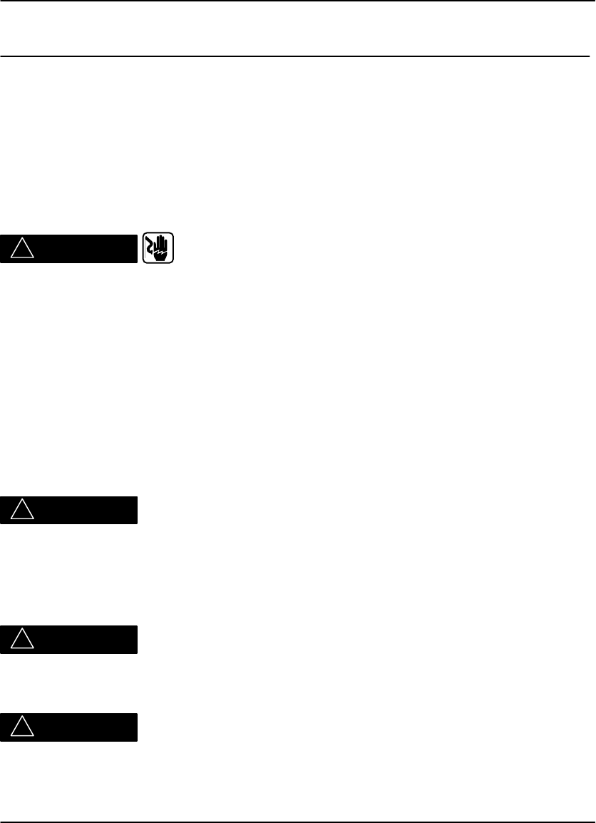
!WARNING
This equipment is operated with hazardous voltage which can shock,
burn, or cause death.
Remove wall plug before servicing equipment. Never pull on cord to remove from
outlet. Grasp plug and pull to disconnect.
Do not operate equipment with a damaged power cord.
Do not use an extension cord to power this equipment.
Use only the power cord supplied with this equipment.
Position the power cord so it will not be tripped over or pulled.
Connect this equipment to a grounded outlet.
!WARNING
This equipment contains moving parts that may be accessible to the user. Loose
clothing, jewelry, or long hair may cause minor personal injury or damage to the
equipment. Do not operate equipment with the covers open. Do not operate
equipment with any of the safety interlocks overridden.
!WARNING
This equipment is not contained in a sealed cabinet. Therefore it must not be used in
locations where it can come in contact with liquids, including bodily fluids.
!WARNING
For continued protection against fire, replace fuses only with fuses of the same type
and rating.
DryView 8100 Laser Imager User Guide
ii 8754020 2000 March Rev.B
Read and understand all instructions before using.
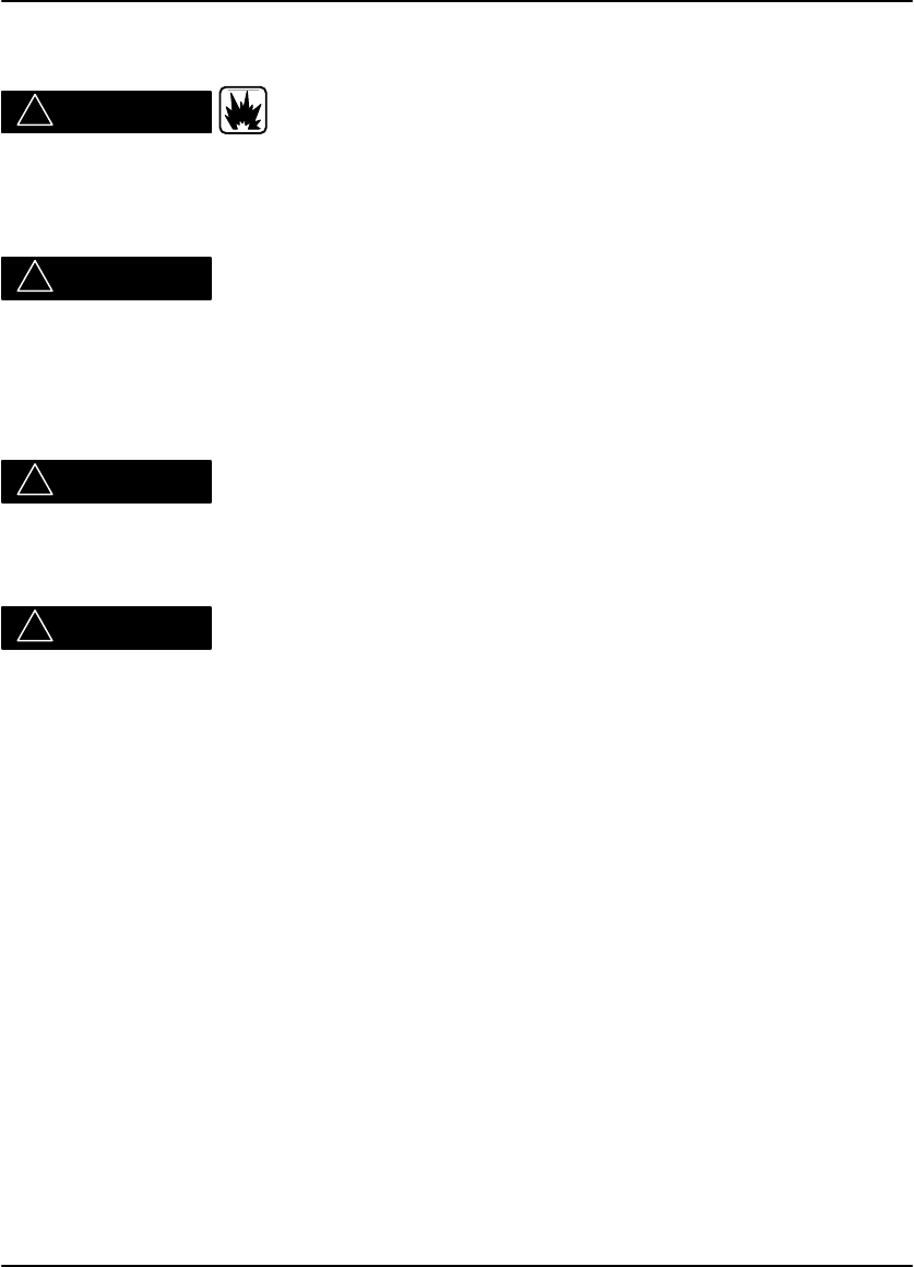
!CAUTION
Do not use in the presence of flammable anesthetics, oxygen or nitrous oxide. This
equipment does not have a gas sealed electronics enclosure and could ignite any
flammable or explosive gases present in its environment.
!CAUTION
This equipment is intended to connect to other medical devices. Installation and
service maintenance are to be performed only by qualified service personnel. The
laser in the equipment is not a patient device. Therefore the equipment must be
installed no closer than 1.83 meters from a patient bed or chair.
!CAUTION
Do not substitute or modify any part of this equipment without approval of Eastman
Kodak Company.
!CAUTION
This equipment has been tested and found to comply with the limits for a Class B
digital device, pursuant to part 15 of the FCC rules. Those limits are designed to
provide reasonable protection against harmful interference in a residential
installation. This equipment generates, uses, and can radiate radio frequency
energy and, if not installed and used in accordance with the instructions, may cause
harmful interference to radio communications. However, there is no guarantee that
interference will not occur in a particular installation. If this equipment does cause
harmful interference to radio or television reception, which can be determined by
turning the equipment off and on, the user is encouraged to try to correct the
interference by one or more of the following measures:
Reorient or relocate the receiving antenna.
Increase the separation between the equipment and the receiver.
Connect the equipment into an outlet on a circuit different from that to which the
receiver is connected.
Consult the dealer or an experienced radio/TV technician for help.
Safety, EMC, and CE Marking Compliance
iii
2000 March Rev. B 8754020
Read and understand all instructions before using.
!CAUTION
General External Cleaning: This equipment may be cleaned with a damp cloth
using water with mild detergent, or commercial electronic equipment cleaner.
8100–38L
DryView 8100 Laser Imager User Guide
iv 8754020 2000 March Rev.B
Read and understand all instructions before using.
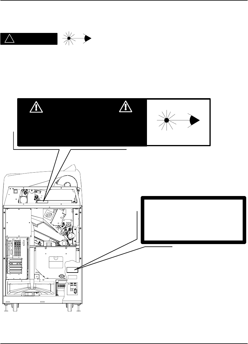
!DANGER
The equipment employs a 50 milliwatt laser. Laser radiation may be present when
the machine operates without the rear cover installed.
Use of controls or adjustments, or performance of procedures other than those
specified herein, may result in eye damage.
The rear cover shall be removed by authorized service personnel only.
6E7000 Rev. A
Class 1 Laser
Laser de catégorie 1
Laser-Klasse 1
Laser di Classe 1
Klass 1 Laser
Bypassing interlocks (other than the Service Interlock above)
will allow the system to run with the laser energized.
Exposure to laser light may result in permanent eye damage.
DANGER
Safety, EMC, and CE Marking Compliance
v
2000 March Rev. B 8754020
Read and understand all instructions before using.

DryView 8100 Laser Imager User Guide
vi 8754020 2000 March Rev.B
This equipment has been tested for and complies with the following Safety and
Emission Standards. Certificates of Compliance and Declarations of Conformity
have been issued as shown below.
Safety:
Canada:
C22.2 NO 950-95–CAN/CSA Safety for Information Technology Equipment,
Including Electrical Business Equipment
C22.2 NO 601.1–M90–CAN/CSA Medical Electrical Equipment – Part 1:
General Requirements for Safety
Europe:
EN60950: Safety of Information Technology Equipment, Including Electrical
Business Equipment (IEC 60950 : 1991, Modified) (Includes Amendment A1 and
A2: 1993)
EN60601–1–1: Medical electrical equipment – Part 1: General requirements for
safety – Section 1: Collateral standard: Safety requirements for medical electrical
systems
EN60825–1: Safety of laser products – Part 1: Equipment classification,
requirements and user’s guide
U.S.A.:
UL 1950: Safety of Information Technology Equipment, Including Electrical
Business Equipment DOD (Bi–National Standard) with UL 2601–1 Medical
Electrical Equipment, Part 1: General Requirements for Safety
21CFR1040.10 Class I: FDA CDRH Code of Federal Regulations Title 21,
Volume 8, Food and Drugs, Part 1040 Performance Standards For
Light–Emitting Products, Section 10 Laser Products
FDA Premarket Notification 510(K): Regulatory Requirements For Medical
Devices
Rest of World:
IEC 950: Safety of information technology equipment
IEC 60601–1–1: Medical electrical equipment – Part 1: General requirements for
safety – Section 1: Collateral standard: Safety requirements for medical electrical
systems
IEC 60825–1: Safety of laser products – Part 1: Equipment classification,
requirements and user’s guide

Safety, EMC, and CE Marking Compliance
vii
2000 March Rev. B 8754020
EMC:
Canada:
CAN/CSA–C108.6–M91 Class A: Limits and Methods of Measurement of
Electromagnetic Disturbance Characteristics of Industrial, Scientific and Medical
(ISM) Radio–Frequency Equipment
Europe:
EN55022 (CISPR 22) Class B Group 1: Limits and Methods of Measurement of
Radio Interference Characteristics of Information Technology Equipment
EN61000–3–2 (IEC 1000–3–2): Electromagnetic compatibility (EMC) – Part 3:
Limits – Section 2: Limits for harmonic current emissions (equipment input
current <= 16 per phase)
EN 61000–4–2 (IEC 1000–4–2): Electromagnetic compatibility (EMC) – Part 4:
Testing and measurement techniques – Section 2: Electrostatic discharge
immunity test. Basic EMC Publication
EN 61000–4–3 (IEC 1000–4–3): Electromagnetic compatibility (EMC) – Part 4:
Testing and measurement techniques – Section 3: Radiated, radio–frequency,
electromagnetic field immunity test
EN 61000–4–4 (IEC 1000–4–4): Electromagnetic compatibility (EMC) – Part 4:
Testing and measurement techniques – Section 4: Electrical fast transient/burst
immunity test. Basic EMC Publication
EN 61000–4–5 (IEC 1000–4–5): Electromagnetic compatibility (EMC) – Part 4:
Testing and measurement techniques – Section 5: Surge immunity test
EN 61000–4–6 (IEC 1000–4–6): Electromagnetic compatibility (EMC) – Part 4:
Testing and measurement techniques – Section 6: Immunity to conducted
disturbances, induced by radio–frequency fields
EN 61000–4–11 (IEC 1000–4–11): Electromagnetic compatibility (EMC) – Part 4:
Testing and measuring techniques – Section 11: Voltage dips, short interruptions
and voltage variations immunity tests
U.S.A.:
FCC Rules and Regulations, Title 47, Part 15, Subpart B, Class B: Radio
frequency devices: Unintentional Radiators
Rest of World:
CISPR 22 Class B Group 1: Limits and Methods of Measurement of Radio
Interference Characteristics of Information Technology Equipment

DryView 8100 Laser Imager User Guide
viii 8754020 2000 March Rev.B
EU Directives:
73/23/EEC Council Directive on the Harmonization of the Laws of Member
States Relating to Electrical Equipment Designed for Use within Certain Voltage
Limits
89/336/EEC Council Directive on the Approximation of the Laws of the Member
States Relating to Electromagnetic Compatibility
93/42/EEC Council Directive Concerning Medical Devices
CE Marking:
Documents concerning the conformance of this product to Council Directive
93/42/EEC of 14 June 1993 concerning Medical Devices can be obtained from the
Eastman Kodak Health Imaging Systems European Representative at:
Kodak AG
Quality Services
Product Safety
70323 Stuttgart
Germany
Phone: ++49 711 406 2993
Fax: ++49 711 406 3513
DOC:
This Class A digital apparatus meets all requirements of the Canadian
Interference-Causing Equipment Regulations.
Cet appareil numérique de la Classe A respecte toutes les exigences du Règlement
sur le matérial brouilleur du Canada.

Table of Contents
ix
2000 March Rev. B 8754020
PLEASE NOTE The information contained herein is based on the experience
and knowledge relating to the subject matter gained by Eastman
Kodak Company prior to publication.
No patent license is granted by this information.
Eastman Kodak Company reserves the right to change this
information without notice and makes no warranty, express or
implied, with respect to this information. Kodak shall not be liable
for any loss or damage, including consequential or special
damages, resulting from the use of this information, even if loss
or damage is caused by Kodak’s negligence or other fault.
Table of Contents
Description Page
Safety, EMC, and CE Marking Compliance i. . . . . . . . . . . .
Introduction 1-1. . . . . . . . . . . . . . . . . . . . . . . . . . . . . . . . . . . . . . . .
Introducing the Kodak DryView 8100 Laser Imager 1-1. . .
System Configurations 1-2. . . . . . . . . . . . . . . . . . . . . . . . . . . .
DryView 8100 Laser Imager 1-2. . . . . . . . . . . . . . . . . . . .
Dryview 8100 PACS Link Laser Imager 1-2. . . . . . . . . .
Keypad Features 1-3. . . . . . . . . . . . . . . . . . . . . . . . . . . . . . . . .
How the DryView 8100 Laser Imager Works 1-4. . . . . . . . .
Automatic Image Quality Control 1-4. . . . . . . . . . . . . . . . . . .
Manual Mode of Operation 1-4. . . . . . . . . . . . . . . . . . . . . . . . .
How This Manual is Organized 1-6. . . . . . . . . . . . . . . . . . . . .
Controls and Indicators 2-1. . . . . . . . . . . . . . . . . . . . . . . . . . . . .
Main Cabinet Controls and Indicators 2-1. . . . . . . . . . . . . . .
Local Panel Functions 2-2. . . . . . . . . . . . . . . . . . . . . . . . . . . . .
Operation and Maintenance 3-1. . . . . . . . . . . . . . . . . . . . . . . . .
System Power Up 3-1. . . . . . . . . . . . . . . . . . . . . . . . . . . . . . . .
Methods for Acquiring and Printing Images 3-2. . . . . . . . . .
Methods for Adjusting Image Density and Contrast 3-2. . .
Adjusting Density from the Local Panel 3-3. . . . . . . . . . . . . .
Adjusting Contrast from the Local Panel 3-4. . . . . . . . . . . . .

DryView 8100 Laser Imager User Guide
x8754020 2000 March Rev. B
Description Page
Producing a Calibration Test Print 3-4. . . . . . . . . . . . . . . . . . .
Operating in Manual Mode 3-5. . . . . . . . . . . . . . . . . . . . . . . . .
Opening the Front Door Via the Local Panel 3-6. . . . . . . . .
Opening the Front Door Manually 3-7. . . . . . . . . . . . . . . . . . .
Opening and Closing the Upper Hood 3-8. . . . . . . . . . . . . . .
Loading/Unloading Film 3-10. . . . . . . . . . . . . . . . . . . . . . . . . . .
Replacing the Charcoal Filter 3-11. . . . . . . . . . . . . . . . . . . . . .
Using the DryView V2 Keypad 4-1. . . . . . . . . . . . . . . . . . . . . . .
DryView V2 Keypad Controls 4-1. . . . . . . . . . . . . . . . . . . . . .
DryView V2 Keypad – Main Menu 4-2. . . . . . . . . . . . . . . . . .
DryView V2 Keypad – Format Menu 4-3. . . . . . . . . . . . . . . .
DryView V2 Keypad – Imager Menu 4-4. . . . . . . . . . . . . . . .
DryView V2 Keypad – Keypad Menu 4-6. . . . . . . . . . . . . . .
Using the Keypad to Format/Acquire/Print 4-8. . . . . . . . . . .
Selecting Auto Print or Auto Format Mode 4-10. . . . . . . . . . .
Using the Keypad to Adjust Image Density 4-11. . . . . . . . . . .
Using the Keypad to Adjust Image Contrast 4-12. . . . . . . . . .
Using the Keypad to Erase Stored Images 4-13. . . . . . . . . . .
DryView V2 Keypad Error Message Table 4-14. . . . . . . . . . .
Troubleshooting 5-1. . . . . . . . . . . . . . . . . . . . . . . . . . . . . . . . . . . .
Operator Troubleshooting 5-1. . . . . . . . . . . . . . . . . . . . . . . . . .
Local Panel Message Types 5-1. . . . . . . . . . . . . . . . . . . . . . .
Status Information 5-1. . . . . . . . . . . . . . . . . . . . . . . . . . . . .
Error Messages or Notices 5-1. . . . . . . . . . . . . . . . . . . . .
Local Panel Status Messages 5-2. . . . . . . . . . . . . . . . . . . . . .
Local Panel Error Messages 5-4. . . . . . . . . . . . . . . . . . . . . . .
Film Drive Problems 5-10. . . . . . . . . . . . . . . . . . . . . . . . . . . . . .
Film Pickup Problems in Area 1 5-11. . . . . . . . . . . . . . . . . . . .
Removing Film Jams from Area 2 5-12. . . . . . . . . . . . . . . . . . .
Removing Film Jams from Area 3 5-13. . . . . . . . . . . . . . . . . . .
Removing Film Jams from Area 4 5-14. . . . . . . . . . . . . . . . . . .

Table of Contents
xi
2000 March Rev. B 8754020
Description Page
Removing Film Jams from Area 5 5-16. . . . . . . . . . . . . . . . . . .
Manually Closing the Film Cartridge 5-17. . . . . . . . . . . . . . . . .
Calling for Support 5-18. . . . . . . . . . . . . . . . . . . . . . . . . . . . . . . .
Specifications 6-1. . . . . . . . . . . . . . . . . . . . . . . . . . . . . . . . . . . . . .
Dimensions 6-1. . . . . . . . . . . . . . . . . . . . . . . . . . . . . . . . . . . . . .
Electrical 6-1. . . . . . . . . . . . . . . . . . . . . . . . . . . . . . . . . . . . . . . .
Operating Environment 6-1. . . . . . . . . . . . . . . . . . . . . . . . . . . .
Environmental Effects 6-1. . . . . . . . . . . . . . . . . . . . . . . . . . . . .
Storage Environment 6-2. . . . . . . . . . . . . . . . . . . . . . . . . . . . .
Film Size 6-2. . . . . . . . . . . . . . . . . . . . . . . . . . . . . . . . . . . . . . . .
Film Throughput 6-2. . . . . . . . . . . . . . . . . . . . . . . . . . . . . . . . . .
Host Control 6-2. . . . . . . . . . . . . . . . . . . . . . . . . . . . . . . . . . . . .
DryView V2 Keypad 6-2. . . . . . . . . . . . . . . . . . . . . . . . . . . . . .
Agency Compliance 6-2. . . . . . . . . . . . . . . . . . . . . . . . . . . . . . .
Technical Information 7-1. . . . . . . . . . . . . . . . . . . . . . . . . . . . . . .
General Description 7-1. . . . . . . . . . . . . . . . . . . . . . . . . . . . . . .
Spectral Sensitivity 7-1. . . . . . . . . . . . . . . . . . . . . . . . . . . . . . .
Image Quality 7-2. . . . . . . . . . . . . . . . . . . . . . . . . . . . . . . . . . . .
Automatic Image Quality Control 7-2. . . . . . . . . . . . . . . . . . .
Less Impact on the Environment 7-3. . . . . . . . . . . . . . . . . . .
Storage and Handling of Undeveloped Film 7-3. . . . . . . . . .
Handling of Developed Film 7-4. . . . . . . . . . . . . . . . . . . . . . . .
Archivability of Developed Film 7-4. . . . . . . . . . . . . . . . . . . . .
Exposure to Moisture 7-4. . . . . . . . . . . . . . . . . . . . . . . . . . . . .
Odor Dissipation 7-5. . . . . . . . . . . . . . . . . . . . . . . . . . . . . . . . . .
Heat Dissipation 7-5. . . . . . . . . . . . . . . . . . . . . . . . . . . . . . . . . .
Film Recycling 7-5. . . . . . . . . . . . . . . . . . . . . . . . . . . . . . . . . . .
IMPORTANT NOTICE TO PURCHASER 7-6. . . . . . . . . . . .

DryView 8100 Laser Imager User Guide
xii 8754020 2000 March Rev. B
BLANK PAGE
Introduction
1-1
2000 March Rev. B 8754020
Introduction
Introducing the Kodak DryView 8100 Laser Imager
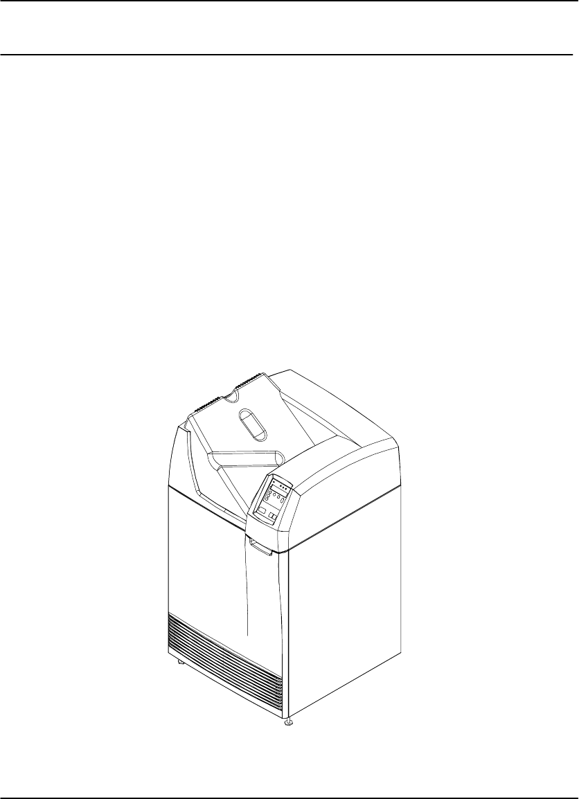
The DryView 8100 Laser Imager is a continuous tone laser imager with an internal
photothermographic film developer. Heat, rather than photo chemicals, is used to
develop the film. The imager can be connected to and print images from a variety of
medical image source devices such as CT scanners or Ultrasound. It can also be
connected to a DICOM medical image network via the PACS Link 9410 Acquisition
System.
The DryView 8100 Laser Imager uses 14 inch x 17 inch (35 cm x 43 cm) DryView
Laser Imaging Film, which is packaged in 125-sheet Kodak Instant Daylight Load
Film Cartridges.
A DryView V2 Keypad can be used to control the imager, or the system can be
controlled from the host modality. A footswitch is also available, providing an optional
method of acquiring images for printing.
Figure 1-1. DryView 8100 Laser Imager

DryView 8100 Laser Imager User Guide
1-2 8754020 2000 March Rev. B
System Configurations
The DryView 8100 Laser Imager can be used in two system configurations. The key
features of these are described below.
DryView 8100 Laser Imager
The imager connects directly to up to three image source devices. (The standard
unit has one input, but it can be upgraded for additional inputs.)
Copper cables are used for connections to the source imaging device and
keypad.
The operator controls image acquisition and printing from either a keypad or a
console on the host source imaging device.
Dryview 8100 PACS Link Laser Imager
The imager connects to a DICOM medical image network via a PACS Link
Interface.
The imager prints images sent from image source devices or archiving stations
connected to the DICOM network.

Introduction
1-3
2000 March Rev. B 8754020
Keypad Features
The table below lists the features provided by the DryView V2 Keypad.
Feature DryView
V2 Keypad
Format Select Yes*
Multiple Copies Setting Yes
Sequential Image Acquire Yes
Random Image Acquire Yes
Sequential Image Erase No
Random Image Erase Yes
Move Acquired Image No
Print Yes
Stop Print No
Density or Dmax Setting Yes**
Contrast Setting Yes**
Print Density Test Yes**
Print Contrast Test Yes**
Smooth/Sharp Select Yes
Image Polarity Select Yes
Image Framing Select No
Auto-Print Select Yes
Auto-Format Select Yes
Alarm Volume Setting Yes
* Available image formats include:
From DryView V2 Keypad: 1:1, 2:1, 4:1, 6:1, 9:1, 12:1, 15:1, 16:1, and 20:1.
From host console: Same as for the DryView V2 Keypad, plus 24:1.
** Can also be set at the imager’s Local Panel.

DryView 8100 Laser Imager User Guide
1-4 8754020 2000 March Rev. B
How the DryView 8100 Laser Imager Works
Using the keypad or host console, the operator acquires an image from the
image source device. The image is stored on a hard disk in the imager.
Using the keypad or host console, the operator prints the image.
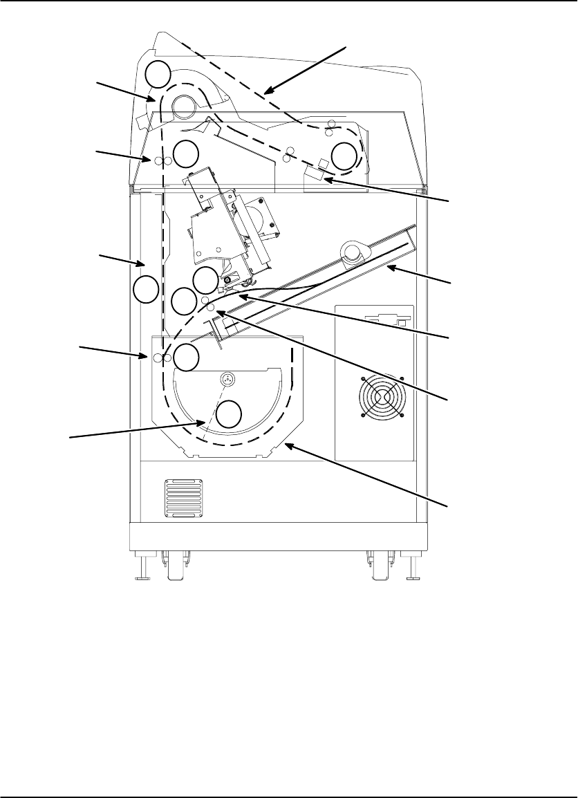
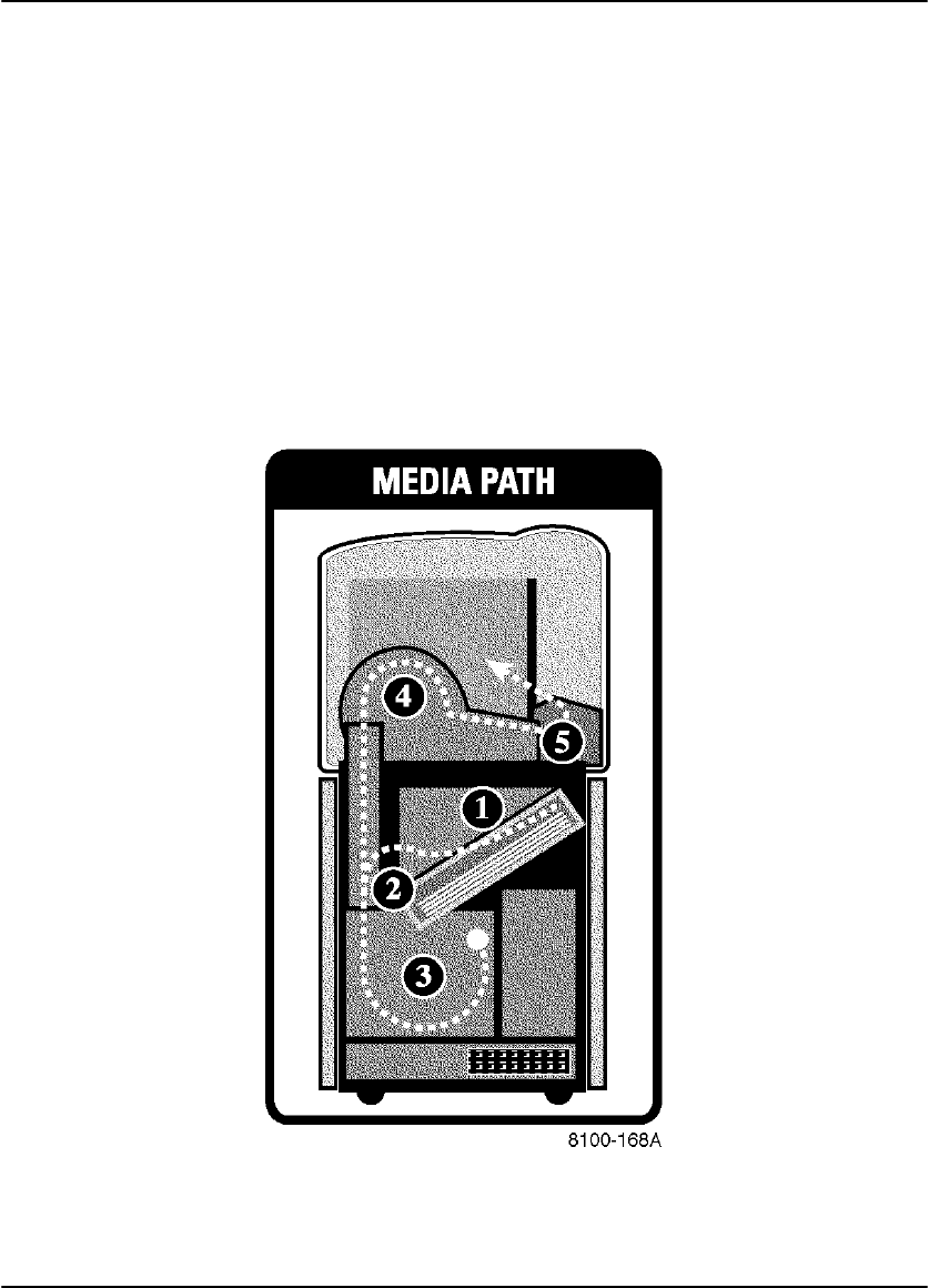
The following sequence occurs each time the operator issues a print command. The
step numbers refer to the circled numbers in Figure 1-2. The dashed lines in the
illustration indicate the film path.
1. Suction cups lift a single sheet of film out of the supply cartridge and route it into
the film feed rollers.
2. The film feed rollers move the film down to the platen rollers.
3. The platen rollers drive the film into the exposure module platen.
4. A moving laser beam writes the image onto film, which is held stationary in the
platen.
5. The platen rollers reverse direction and move the exposed film up through the
vertical transport area.
6. Transport rollers drive the film onto the processor drum.
7. The heated processor drum develops the film as it passes over the drum.
8. Rollers move the developed film from the processor drum, through the
densitometer (see the next paragraph), and onto the receive tray.
Automatic Image Quality Control
The built-in densitometer is a key element in the Automatic Image Quality Control
(AIQC) process. AIQC allows the imager to automatically adjust processing
parameters to ensure optimum image quality. The imager adjusts these parameters
each time it prints a calibration film. A calibration film is printed whenever:
The DryView 8100 Laser imager is powered on.
A calibration film is requested from the Local Panel.
The imager has not been used for 7 days, and a print is requested.
Manual Mode of Operation
The imager can be operated in a “manual” mode, without AIQC. Use of this mode is
explained in Section 3 of this manual.
Introduction
1-5
2000 March Rev. B 8754020
Vertical
Transport
Area
Receive Tray
Film
Supply
Cartridge
Exposure
Module
Film
Processor
Drum
1
2
3
4
8
8100–49C
Suction
Cups
Film Feed
Rollers
Densitometer
Transport
Rollers
Platen
Rollers
Laser
Beam
5
6
7
Figure 1-2. Print Sequence

DryView 8100 Laser Imager User Guide
1-6 8754020 2000 March Rev. B
How This Manual is Organized
The remainder of this manual is organized as follows:
Section 2 describes operator controls and indicators on the main cabinet,
including the Local Panel.
Section 3 provides general procedures for operating and maintaining the system.
(It does not include instructions for using the keypad. These are provided in
Section 4.)
Section 4 provides instructions for using the DryView V2 Keypad, including:
descriptions of keypad controls, procedures for operating the imager from the
keypad, and keypad error messages.
Section 5 includes system troubleshooting procedures.
Section 6 provides system specifications.
Section 7 includes technical information about DryView 8100 Laser Imaging
Film.
Controls and Indicators
2-1
2000 March Rev. B 8754020
Controls and Indicators
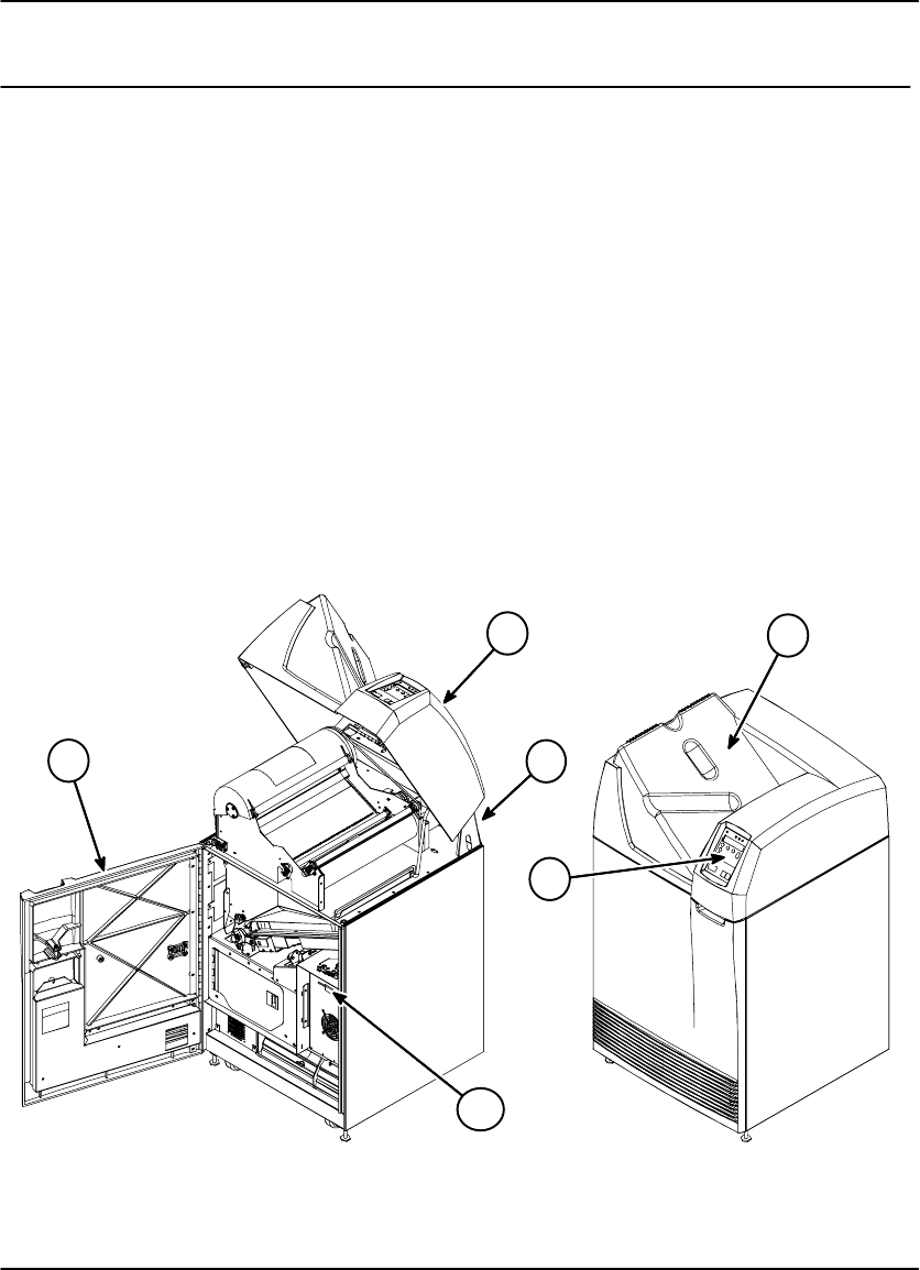
Main Cabinet Controls and Indicators
This section describes the operator controls on the DryView 8100 Laser Imager
cabinet, focusing on the Local Panel. For keypad functions, refer to Section 4.
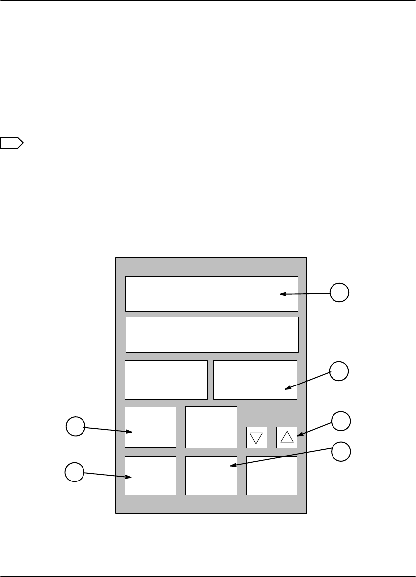
The numbered descriptions below correspond to the circled numbers in Figure 2-1.
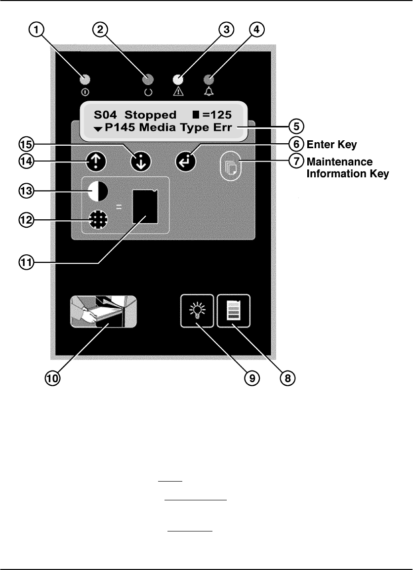
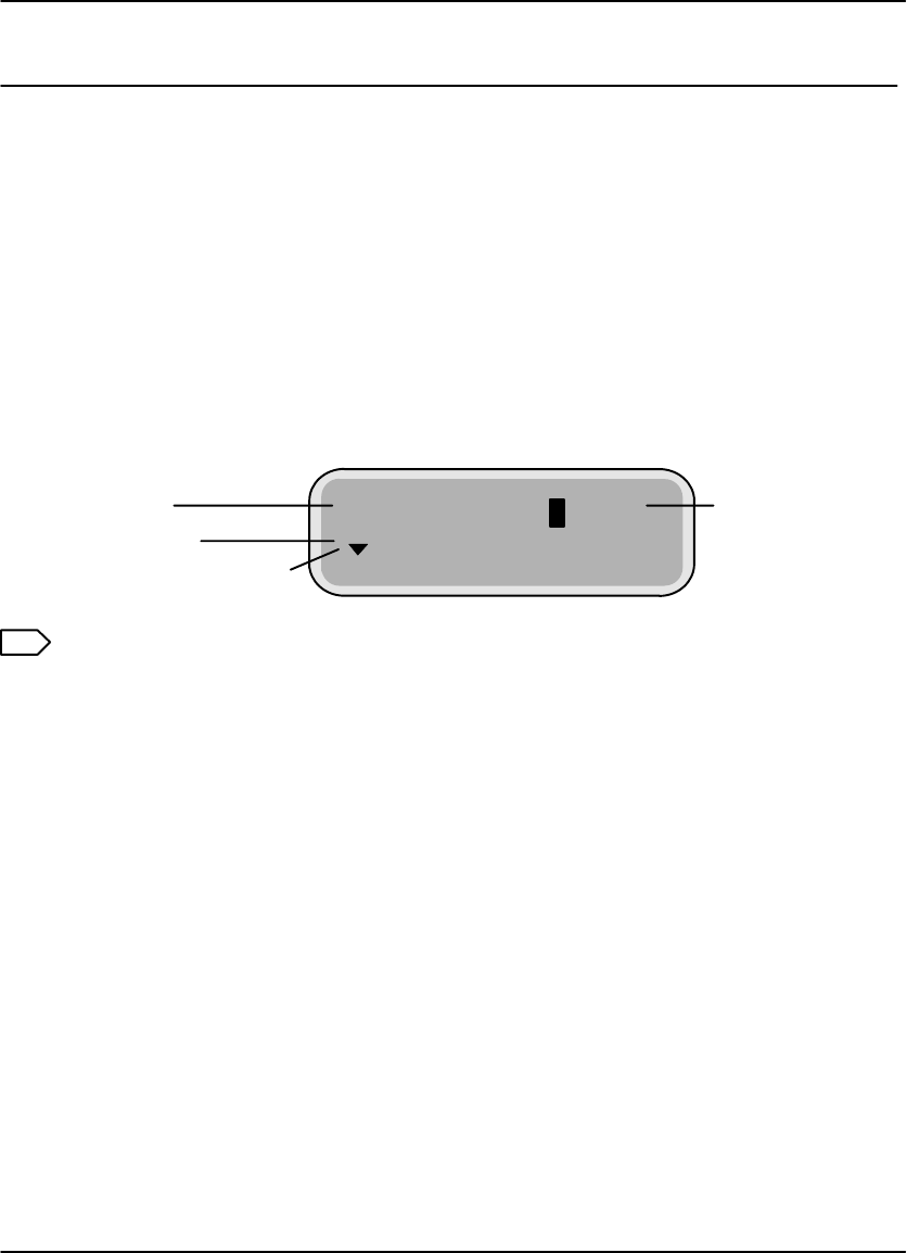
1. Local Panel – Includes a message display, status indicator lights, and
pushbutton controls. The Local Panel is described in greater detail on the
following pages.
2. Power Switch – Controls power to the imager. (On rear of cabinet.)
3. Front Door – Accesses the film cartridge.
4. Upper Hood - Accesses upper assemblies.
5. Receive Tray – Collects developed film.
6. Floppy Disk Drive – Used to update the imager internal software.
2
4
3
5
68100–27C
1
Figure 2-1. DRYVIEW 8100 Laser Imager – Controls and Indicators

DryView 8100 Laser Imager User
2-2 8754020 2000 March Rev. B
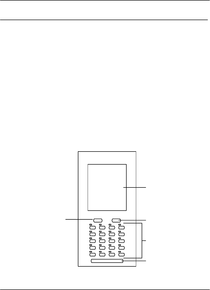
Local Panel Functions
This paragraph describes the controls and indicators on the Local Panel. Use of
these controls is covered in Section 3. Display window messages are explained in
Section 6.
1. Power Light – Indicates that the imager is powered up.
2. Ready Light – ON: Indicates that the imager is available for printing.
– Blinking:Indicates that the imager is printing.
– OFF: Indicates that the imager is not available for printing.
3. Attention Light – Indicates an error condition that may affect imager operation
(e.g., imager warming or film low). Check the display window for a related
message.
4. Alarm Light – Indicates that an error condition exists (e.g., a film jam or open
door), and imager operation cannot continue until the error has been cleared.
Check the display window for a related message.
5. Display Window – Provides information about the status and function of the
imager and the prints in progress. Refer to Section 5 for descriptions of the
messages displayed in this window.
6. o (Enter) Key – Press to enter a selected value or to return to the status and
error screen.
After you have changed the contrast or density setting, press o to lock in the
new setting.
After viewing maintenance information or IP addresses on the message
display, press o to return to the status and error message screen.
7. Maintenance Information Key – Press to display a scrollable list that includes:
Maintenance information such as total lifetime print count and number of
prints remaining until preventive maintenance is required.
IP address of the imager.
Reserved service IP address.
8. Calibrate Key – Press to print a calibration test (step wedge pattern) as the next
film. (The test film will interrupt a multiple-sheet print job.)
Controls and Indicators
2-3
2000 March Rev. B 8754020
Figure 2-2. Local Panel Controls
9. Backlight Key – When system power is applied, the message display backlight
turns on and the Ready, Attention, and Alarm lights are enabled for use.
Press the Backlight key once to turn off the backlight.
Press the Backlight key a second time to disable the Ready, Attention, and
Alarm lights. The backlight remains off. (This is darkroom mode.)
Press the Backlight key a third time to return the backlight and the three
indicator lights to their original state (enabled for use).

DryView 8100 Laser Imager User
2-4 8754020 2000 March Rev. B
10. Open Door Key – Press momentarily to open the front door. The film cartridge
first closes to prevent exposing the film. Then the front door is unlatched.
If a film jam at the cartridge prevents the cartridge from closing, error message
P138 (Press Open 5S) will display. This indicates that you must hold down the
Open Door key for 5 seconds to unlatch the door. Since the film cartridge is
open, when you open the door the top sheets of film will be exposed. To
minimize exposure, you should make the room as dark as possible before
opening the door.
! Caution
Do not leave the imager unattended after pressing the Open Door Key.
11. Test Print Key – Press this key after you press the Contrast or Density key, to
initiate a test print for examination of contrast or density.
12. Density Key – Press this key to display and change the density setting. Use the
= and O keys to adjust the setting up or down (The density range for blue film is
from 1.7 to 3.1. For clear film it is from 1.7 to 3.0.) Then press the Test Print or
Enter key to apply the new setting. (Do not use this key to change density if your
system includes a DryView V2 keypad.)
Note
If your system includes the DryView V2 keypad, density must be set via the
keypad rather than the Local Panel. The values set at the keypad will override
values entered at the Local Panel.
13. Contrast Key – Press this key to display and change the contrast setting. Use
the = and O keys to adjust the setting up or down ( range: -15 to -1 and 1 to 15).
Then press the Test Print or Enter key to apply the new setting.
Note
If your system includes the DryView V2 keypad, contrast must be set via the
keypad rather than the Local Panel. The values set at the keypad will override
values entered at the Local Panel.
14. = Key– Press to move up through item lists or increase a parameter value.
15. O Key – Press to move down through item lists or decrease a parameter value.
Operation and Maintenance
3-1
2000 March Rev. B 8754020
Operation and Maintenance
System Power Up
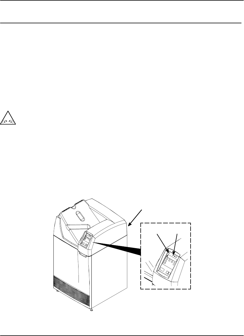
1. Set the imager Power Switch to ON. (The Local Panel Power light will turn on.)
The imager performs a series of self-diagnostic tests and begins a warmup
cycle. (The time required for warmup varies based on how long the imager
has been turned off. The maximum warmup time at normal room temperature
is about 25 minutes.)
After the diagnostic tests and warmup cycle are complete, the Local Panel
displays SO1 Ready and the Ready light turns ON.
! Caution
On occasion the imager may have to perform file maintenance on its hard disk
after power on. When this occurs, the message P154 Disk Maint displays on
the Local Panel. The process may require several minutes. To avoid longer
delays, NEVER turn off power during disk maintenance. As long as the P154
Disk Maint message is displayed, the system is operating correctly.
2. You can acquire images during the warmup cycle, but the system will not print
until the Ready light turns on.
Power Switch
(Rear Cabinet)
Local
Panel
Power
Light
Ready
Light
Figure 3-1. Power Switch and Local Panel

DryView 8100 Laser Imager User Guide
3-2 8754020 2000 March Rev. B
Methods for Acquiring and Printing Images
The basic operator functions required to acquire and print images on film are the
following:
1. Selecting the number of copies to print.
2. Selecting the format (order) in which the images will be printed on film.
3. Acquiring the images from the host modality and storing them on hard disk in the
imager.
4. Printing the stored images on film.
Other operator functions include:
1. Erasing images stored on disk (before printing).
2. Stopping a requested print job.
The operator functions listed above can be processed in different ways:
From a host console, using software programmed specifically for imager control.
(See the host user documentation for operator instructions.)
From a DryView V2 Keypad. (If your system includes this keypad, see Section 4
for detailed procedures.)
Note
An optional footswitch can be used for acquisition of images from the host
modality.
Methods for Adjusting Image Density and Contrast
These image quality control functions can be performed in two ways:
From the imager Local Panel, if your system does not include a DryView V2
keypad. (See the instructions on the following pages in this section.)
From a DryView V2 Keypad. (If your system includes this keypad, see Section 4
for instructions. If it does not include this keypad, the procedures must be
performed from the Local Panel.)
Operation and Maintenance
3-3
2000 March Rev. B 8754020
Adjusting Density from the Local Panel
Note
If your system includes the DryView V2 Keypad, do not use this Local Panel
procedure. Use the keypad procedure described in Section 4. Values set at the
keypad will override any values set in the Local Panel.
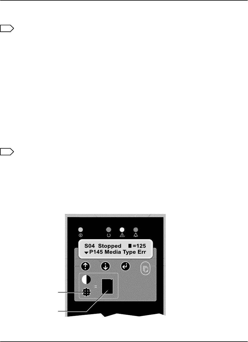
1. Press the Density key. The display will show DMAX = x.x. The number x.x is the
value of the maximum density desired.
2. Press the Test Print key. The imager will print a SMPTE test print.
3. Examine the test print. If the maximum density on the test print is not
acceptable, follow the steps below to adjust density.
4. Press the Density key.
5. Press the =key to increase density or the O key to decrease density. The display
will show the new density value. Repeat steps 2 and 3 until you reach an
acceptable maximum density.
Note
If you know the desired Dmax value, you can simply enter the value without
printing a test print. Follow the steps below.
1. Press the Density key.
2. Press the =or O key until the desired value is displayed.
3. Press the o (Enter) key to lock in the new value.
8100 76L
Density
Test
Print
Figure 3-2. Local Panel Controls

DryView 8100 Laser Imager User Guide
3-4 8754020 2000 March Rev. B
Adjusting Contrast from the Local Panel
Note
If your system includes the DryView V2 Keypad, do not use this Local Panel
procedure. Use the keypad procedure described in Section 4. Values set at the
keypad will override any values set in the Local Panel.
After acquiring an image, perform the following steps at the Local Panel.
1. Press the Contrast key.
The display will show CONTRAST = x, where x is a positive number from 1 to 15
if the image is positive, or a negative 1 to 15 if the image is negative.
2. Press the Test Print key.
The imager will print a contrast print. The image you acquired is printed 15 times
on a single film, using contrast values of 1 through 15 if a positive image was
selected. If a negative image was selected, contrast values of negative 1
through 15 are used. Contrast values are printed under each image.
Note
If the size of the acquired image is too large for a 15:1 format, the imager will
print a contrast test of the internal SMPTE image.
3. Examine the contrast print and choose the most desirable contrast value.
4. Press the Contrast key again.
5. Use the =or O key to scroll to the chosen contrast value.
6. Press the o(Enter) key to lock in the new value.
Note
If you know the desired contrast value, you can ignore steps 2, 3, and 4.
Producing a Calibration Test Print
To produce a calibration print (step wedge pattern) as the next film, press the
Calibrate key on the Local Panel. (The system will interrupt a multiple-sheet print job
to produce the calibration print.)

Operation and Maintenance
3-5
2000 March Rev. B 8754020
Operating in Manual Mode
The calibration sheets produced by the imager (and the density patch at the top of
each film) are products of the Automatic Image Quality Control (AIQC) system. This
system ensures that density, contrast and other image quality parameters are
constantly fine-tuned to produce high quality images.
An error code P631 or P632 displayed on the Local Panel indicates that calibration
has failed, that a print has failed to meet the AIQC standard. This occurrence is
usually the result of aging film, and if you load a new film cartridge the error probably
will not recur. If, however, the error does recur with the new film, you will have to call
service to analyze the problem. Until the Field Engineer arrives, you can choose to
run the imager in “manual” mode, without AIQC. To operate in manual mode:
1. Simultaneously press the O Key and the Calibrate Key on the Local Panel. The
message P561 Manual Mode will display.
Note
While manual mode is in effect, the imager will not produce calibration prints
and prints will not include density patches.
2. Run a print and check image quality. As long as image quality is acceptable, you
can continue to run prints until the Field Engineer has repaired the imager
problem. At this point you can resume operating with AIQC in effect.
3. To exit manual mode and enter AIQC mode, press the Calibrate Key on the
Local Panel. (Loading a new film cartridge will return the imager to AIQC mode, if
the new film is within the required operating parameters.)
Note
Manual Mode can be entered only when the P631 or P632 error code has been
displayed.
DryView 8100 Laser Imager User Guide
3-6 8754020 2000 March Rev. B
Opening the Front Door Via the Local Panel
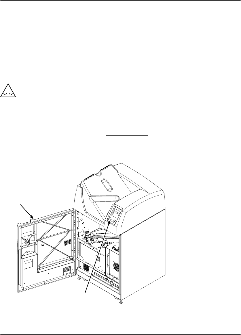
During normal machine operation, you will occasionally need to open the front door
(with power applied) to load and unload film cartridges, or to change the charcoal
filter. Also, if a film jam should occur in the lower part of the imager, you will need to
open the front door to clear the jam.
1. Press and release the Open Door key on the Local Panel (see Figure 3-3). The
imager will close the film cartridge, to avoid exposing film, and then unlatch the
door.
! Caution
Do not leave the imager unattended when the front door is open.
2. A film jam can prevent the film cartridge from closing. When this occurs, the front
door will not open normally. In this case you can hold down the Open Door key
for 5 seconds to unlatch the door without closing the film cartridge. Several
sheets of film at the top of the cartridge will be exposed. You can minimize film
exposure by making the room as dark as possible.
Front Door
Local Panel
Open Door Key
Figure 3-3. Opening the Front Door Via the Local Panel

Operation and Maintenance
3-7
2000 March Rev. B 8754020
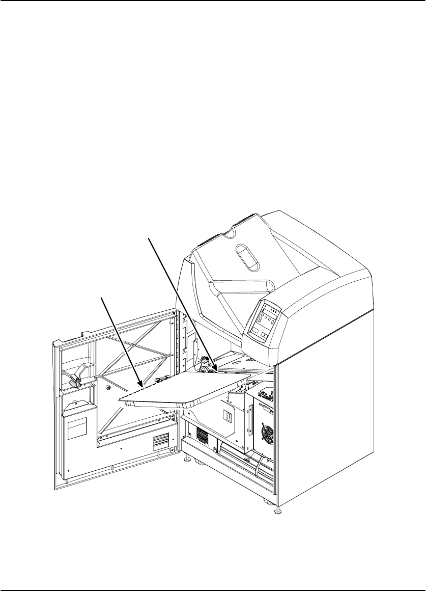
Opening the Front Door Manually
When power is not applied to the imager, you will of course will not be able to open
the front door via the Local Panel. Use the following “manual” procedure to open the
door.
1. Open the upper hood (see the next page).
2. Insert a thin pencil (or other small instrument) into the slot on the right side of the
processor base (see Figure 3-4).
3. Press down to open the front door.
Door Open Slot
Front Door
Figure 3-4. Opening the Front Door Manually

DryView 8100 Laser Imager User Guide
3-8 8754020 2000 March Rev. B
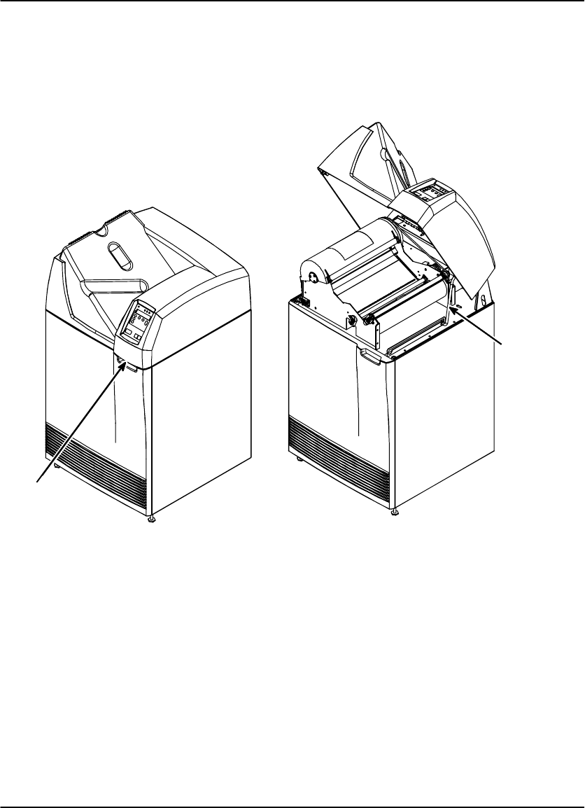
Opening and Closing the Upper Hood
If a film should jam in the developer area, you will have to lift the upper hood to clear
the jam.
Open the upper hood as follows:
1. Grasp the hood at the recessed slot below the Local Panel (see View A in Figure
Figure 3-5).
! Caution
Whenever you raise or lower the hood, grasp it only in the area of the
recessed slot below the Local Panel to avoid possibly pinching your fingers.
2. Raise the hood until the prop rod falls into the slot at the end of its travel (see
View B in Figure Figure 3-5).
Close the hood as follows:
1. Raise the hood slightly to lift the prop rod out of its slot, and pull the prop rod
slightly forward from the slot.
! Caution
Close the hood carefully. Releasing and dropping it could damage the laser.
2. Gently lower the hood to its closed position.
Operation and Maintenance
3-9
2000 March Rev. B 8754020
View A View B
Grasp
Hood
Here
Hood
Prop Rod
Figure 3-5. Opening and Closing the Upper Hood
DryView 8100 Laser Imager User Guide
3-10 8754020 2000 March Rev. B
Loading/Unloading Film
1. To access the film cartridge, press the Open Door key on the Local Panel. This
will close the film cartridge cover and then unlock the front door.
2. Open the front door to access the film cartridge.
3. To remove the film cartridge, lift the edge of the cartridge slightly, then pull the
cartridge out of the imager.
4. To install the film cartridge, insert it into the cartridge slot as shown in Figure 3-6.
5. Slide the cartridge into the imager.
6. Close the front door.
Film Cartridge is inserted
long edge first
Perforations
to the left
8100–30C
Figure 3-6. Loading and Unloading Film
Operation and Maintenance
3-11
2000 March Rev. B 8754020
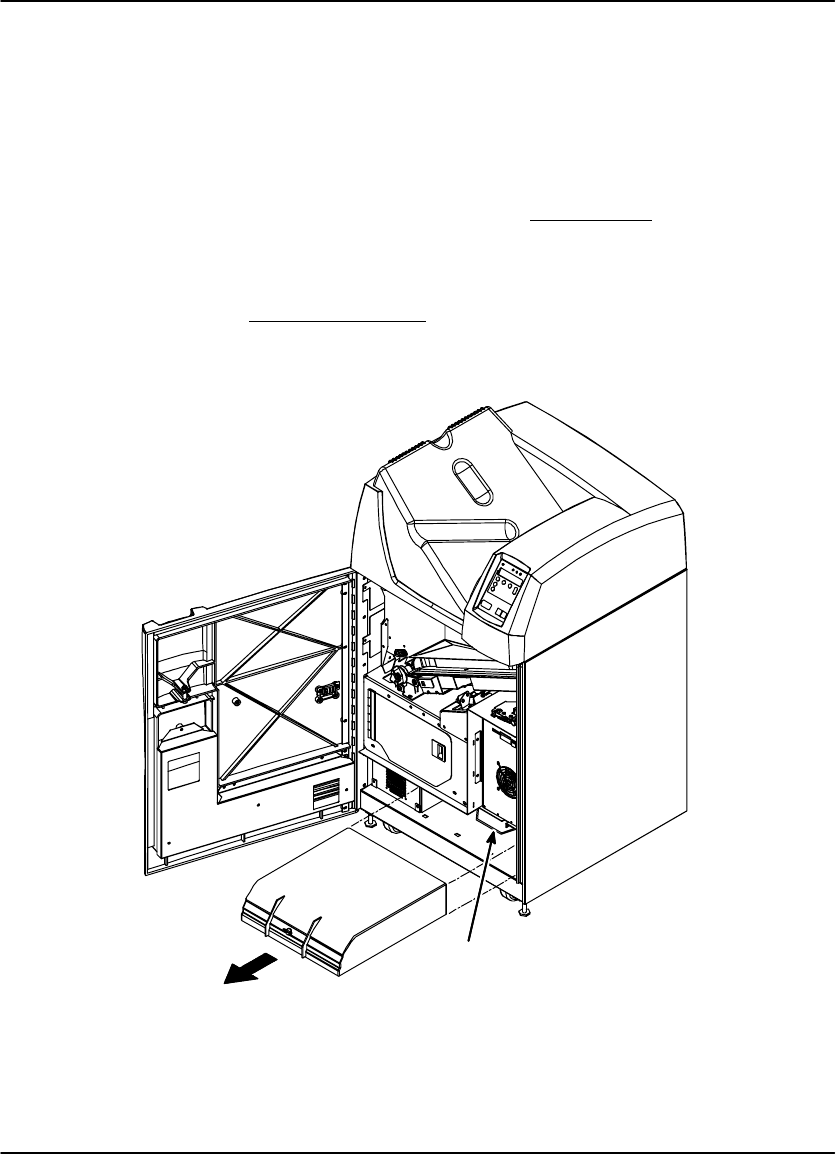
Replacing the Charcoal Filter
DryView Laser Imaging Film emits a slight odor while it develops. The charcoal filter
absorbs and neutralizes this odor. As the imager is used, the filter becomes less
effective. When the odor become noticeable you should replace the filter.
1. Open the front door.
2. Push the retaining clip on the top front of the filter back and up (see Figure 3-7)
and pull out the old filter.
3. Slide the new filter in all the way to the back stop.
4. Pull the retaining clip forward and down to lock the filter in position.
5. Close the front door.
Pull
Out
Filter
Retaining
Clip
Figure 3-7. Replacing the Charcoal Filter

DryView 8100 Laser Imager User Guide
3-12 8754020 2000 March Rev. B
BLANK PAGE
Using the DryView V2 Keypad
4-1
2000 March Rev. B 8754020
Using the DryView V2 Keypad
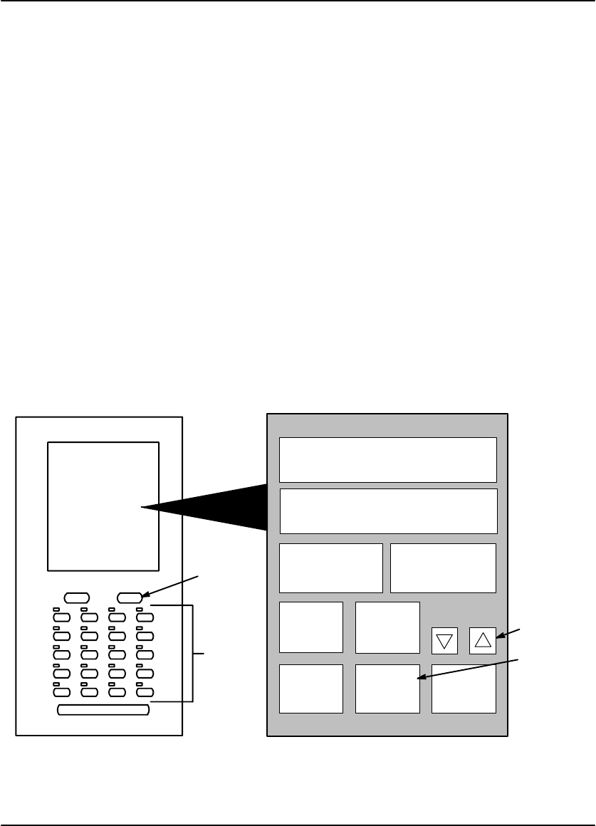
DryView V2 Keypad Controls
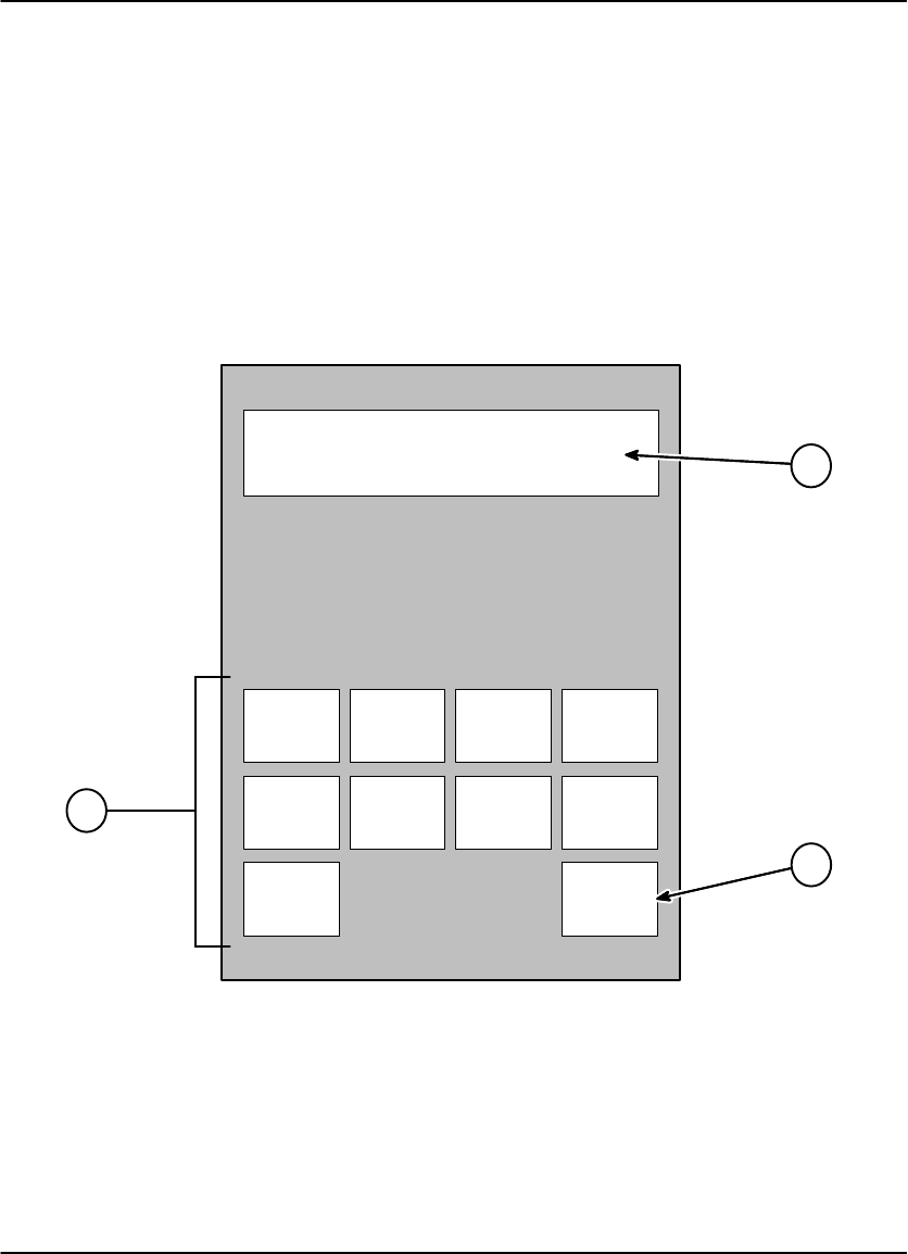
The numbered descriptions below correspond to the numbered callouts in
Figure 4-1.
1. Touch Screen – Displays a variety of menus used for system configuration and
operation. These menus are described in detail on the following pages.
2. Print Key – Places a print request in the print queue.
3. Store Keys – Used to acquire and store images in specific positions for printing.
LEDs above each button indicate used (red) and available (green) storage
locations.
4. Sequential Store Key – Used to acquire and store images in sequential order,
starting in the top row of a rectangular grid, and working from left to right in each
row.
5. Erase Key – Used to enter Erase Image mode, which allows for random erasure
of any or all stored images.
1
2
3
4
5
Figure 4-1. DryView V2 Keypad
DryView 8100 Laser Imager User Guide
4-2 8754020 2000 March Rev. B
DryView V2 Keypad – Main Menu
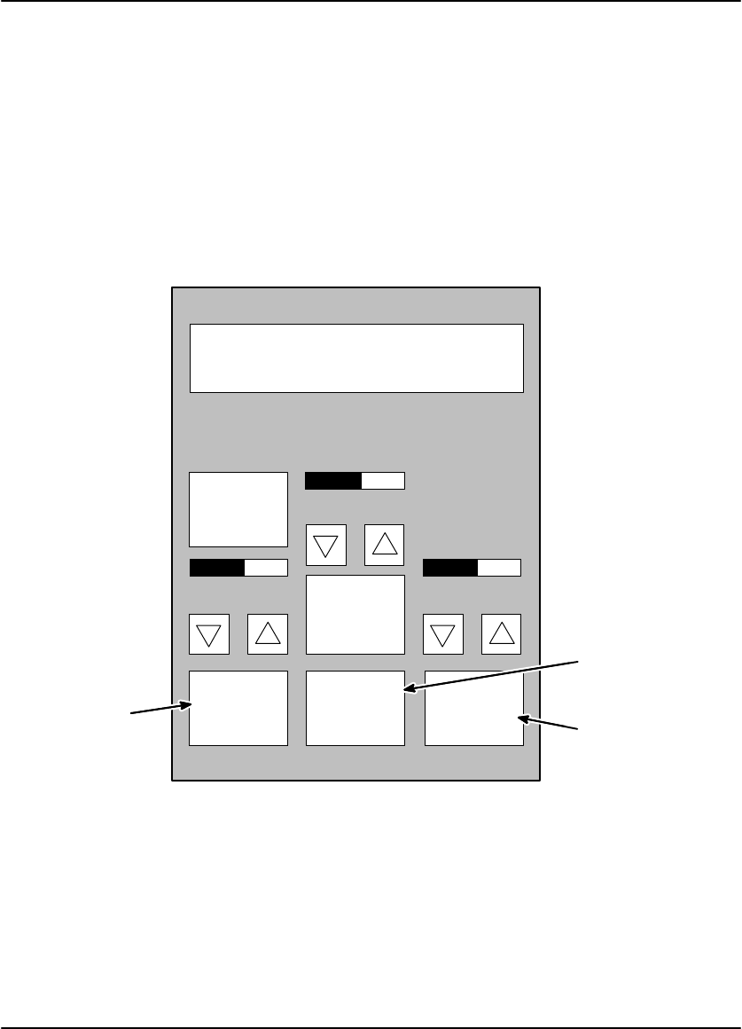
The numbered descriptions below correspond to the numbered callouts in Figure 4-2
1. Attention Message Area – Displays system status and error messages.
2. Imager Print Information Area – Displays the total number of prints that have
been completed.
3. Copy Count Set Keys – Increase or decrease the copy count (range: 1 - 99).
4. Format Menu Key – Accesses the Format Menu.
Note
When in Erase Image mode, the Erase All Images key is displayed in place of
the Format Menu key. The Erase All Images key is used to erase all stored
images from the current format.
5. Keypad Menu Key – Used to access the Keypad Menu.
6. Imager Menu Key – Used to access the Imager Menu.
Laser Imager Status:
MAIN MENU
Ready
Printed: 0
Imager
Menu
Keypad
Menu
Format
Menu
Erase Print
Copies: 1
1
2
3
4
5
6
Figure 4-2. DryView V2 Keypad – Main Menu
Using the DryView V2 Keypad
4-3
2000 March Rev. B 8754020
DryView V2 Keypad – Format Menu
The numbered descriptions below correspond to the numbered callouts in
Figure 4-3.
1. Attention Message Area – Displays system status and error messages.
2. CANCEL Key – Used to return to the Main Menu without selecting a format.
3. Format Select Keys – Used to select the desired image format. Keys are
displayed only for those formats that are currently available. These include nine
fixed formats.
NGLI-16L
Laser Imager Status:
Ready
FORMAT MENU
20 CANCEL
12 15 169
2461
2
1
3
Figure 4-3. DryView V2 Keypad – Format Menu

DryView 8100 Laser Imager User Guide
4-4 8754020 2000 March Rev. B
DryView V2 Keypad – Imager Menu
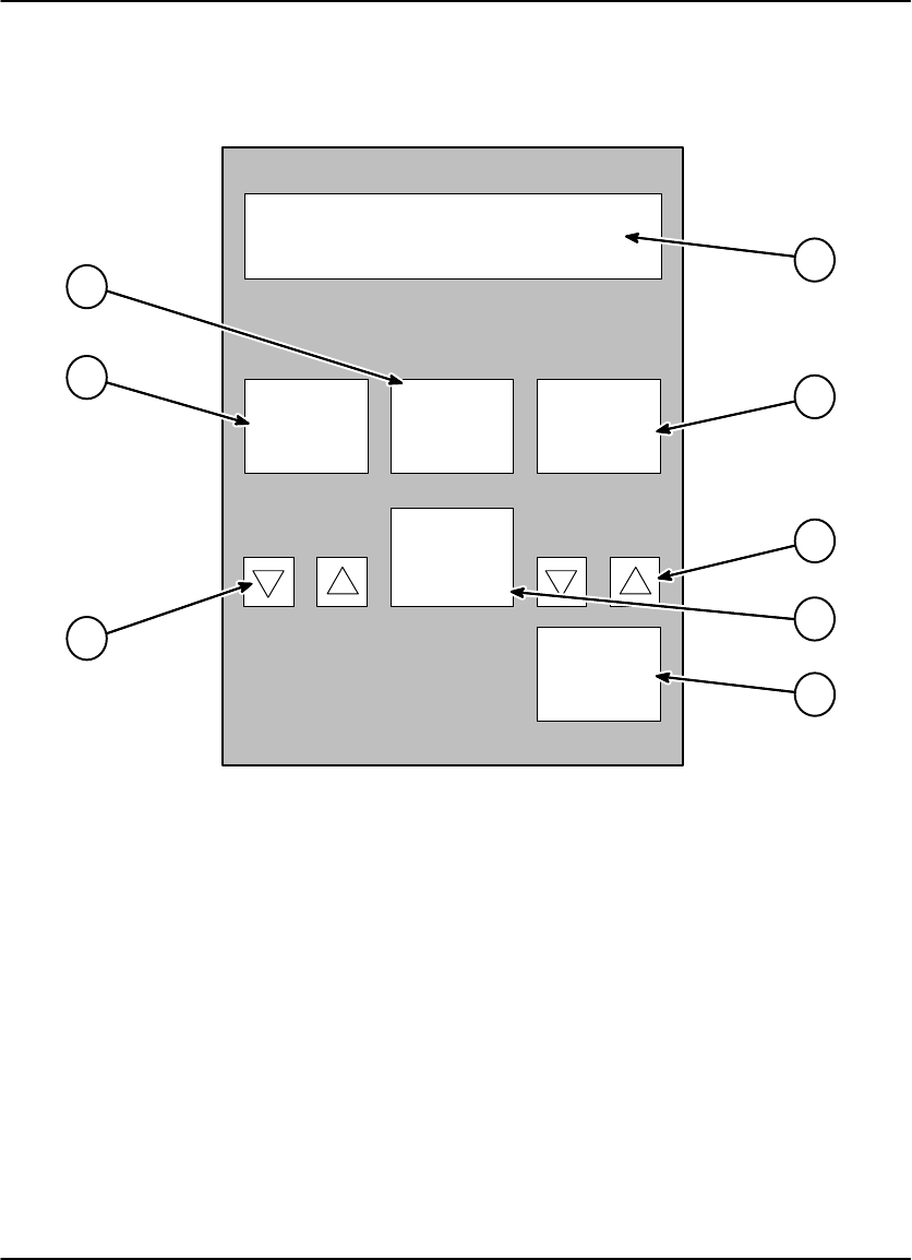
The numbered descriptions below correspond to the numbered callouts in
Figure 4-4.
1. Attention Message Area – Displays system status and error messages.
2. Print Density Test Film Key – Initiates the printing of a density test film
containing a SMPTE test pattern.
3. Density Set Keys – Used to increase or decrease the density setting. If AIQC
(Automatic Image Quality Control) is active, the selected Dmax setting is
displayed (range: 1.70 – 3.10 for blue film, and 1.70 to 3.00 for clear film).
4. Imager Polarity Key – Selects positive or negative image polarity.
5. Return Key – Used to return to the Main Menu.
6. Contrast Set Keys – Used to increase or decrease the contrast setting (range: 1
– 15).
7. Print Contrast Test Film Key – Initiates the printing of a contrast test film. The
last image stored is printed in a 15:1 format, using 15 different contrast settings.
8. Image Processing Key – Selects smooth or sharp image processing. (The
choice depends on the personal preference of the viewer.)
Using the DryView V2 Keypad
4-5
2000 March Rev. B 8754020
NGLI-17L
8
Laser Imager Status:
IMAGER MENU
Ready
Print
Contrast
Test Film
Imager
Polarity
NEGATIVE
Return
2
3
4
5
1
Image
SMOOTH
Contrast: 2 Dmax: 2.7
Print
Density
Test Film
6
8
7
6
Figure 4-4. DryView V2 Keypad – Imager Menu

DryView 8100 Laser Imager User Guide
4-6 8754020 2000 March Rev. B
DryView V2 Keypad – Keypad Menu
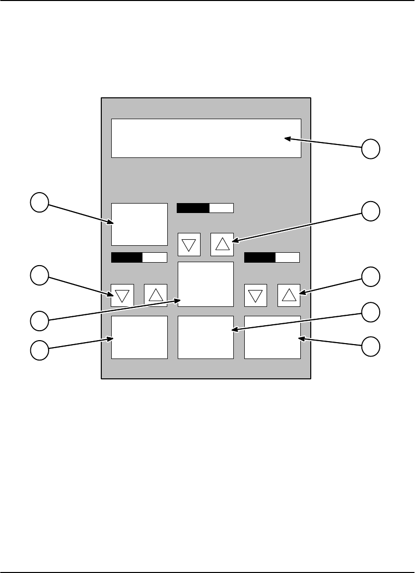
The numbered descriptions below correspond to the numbered callouts in
Figure 4-5.
1. Attention Message Area – Displays system status and error messages.
2. Display Brightness Set Keys – Increase or decrease the keypad display
brightness.
3. Alarm Beep Volume Set Keys – Increase or decrease the volume of the keypad
alarm beep.
4. Return Key – Used to return to the Main Menu.
5. Auto Print Key – Sets the Auto Print function to ON or OFF. When set to ON, a
print is automatically queued after the last image is stored (the Print key does
not have to be pressed).
6. Auto Format Key – Sets the Auto Format function to ON or OFF. When set to
ON, a new format is automatically displayed (i.e., the LEDs above the Store keys
change from red to green) after a print is queued.
7. Color Blind Mode Key – Sets the Color Blind feature to ON or OFF. When set to
ON, the red LEDs above the Store keys (which indicate used storage locations)
blink instead of staying on constantly. This allows the red LEDs to be
differentiated from the constant green LEDs (which indicate available storage
locations).
Note
When in Erase Image mode, the red LEDs blink regardless of whether the
Color Blind feature is ON or OFF.
8. Key Beep Volume Set Keys – Set the key beep volume.
9. Reset Local Print Counter Key – Resets the print counter on the Main Menu
Display.
Using the DryView V2 Keypad
4-7
2000 March Rev. B 8754020
NGLI-18L
9
Laser Imager Status:
KEYPAD MENU
Ready
Reset
Local Print
Counter
Auto
Format:
OFF
Auto
Print:
OFF
Color
Blind
Mode:
OFF
Return
Key Beep
Volume
Alarm Beep
Volume
Display
Brightness
6
7
8
2
3
5
4
1
Figure 4-5. DryView V2 Keypad – Keypad Menu
DryView 8100 Laser Imager User Guide
4-8 8754020 2000 March Rev. B
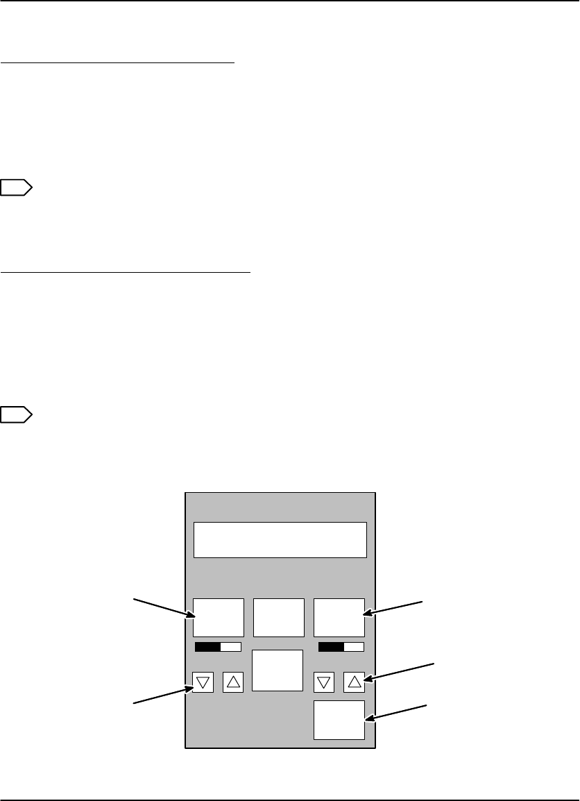
Using the Keypad to Format/Acquire/Print
1. Power up the imager.
2. On the keypad’s Main Menu, press the Copy Count Set keys (see Figure 4-6) to
select the number of copies desired.
3. Press the Format Menu key to access the Format Menu. On that menu, press
the appropriate Format Select key to select the desired format.
4. Press the appropriate Store keys to acquire images.
When an image has been successfully acquired, the light above the
corresponding Store key changes from green to red.
The images are stored on a hard disk in the imager. You can acquire up to
the number of images in the format you selected. For example, if you are
using the 6–image format, you can acquire only six images. You must then
print before you can acquire more images.
5. Once all the images have been acquired for a single film, press the Print key to
place a print request in the print queue.
Laser Imager Status:
MAIN MENU
Ready
Printed: 0
Imager
Menu
Keypad
Menu
Format
Menu
Erase Print
Copies: 1
Print
Store
Keys
Copy
Count
Format
Menu
Figure 4-6. Formatting/Acquiring/Printing

Using the DryView V2 Keypad
4-9
2000 March Rev. B 8754020
Note
If the Auto Print function is ON, a print request is automatically placed in the
print queue as soon as the last image in the format has been stored. (See the
next paragraph for instructions for selecting Auto Print.)
6. At this point, you can select a new format and continue acquiring images.
If the Auto Format function is ON, the red lights above the Format keys will
change to green, indicating that you can start acquiring more images. (See
the next paragraph for instructions for selecting Auto Format.)
If the Auto Format function is OFF, you cannot acquire more images until you
select a new format or you erase currently stored images using the Erase
Image function (see page 5-13).
DryView 8100 Laser Imager User Guide
4-10 8754020 2000 March Rev. B
Selecting Auto Print or Auto Format Mode
1. On the Main Menu, press the Keypad Menu key to access the Keypad Menu.
2. On the Keypad Menu (see Figure 4-7):
To select the Auto Print mode, press the Auto Print key so it indicates ON.
To select Auto Format, press the Auto Format key so it indicates ON.
Press Return.
Laser Imager Status:
KEYPAD MENU
Ready
Auto
Format:
OFF
Auto
Print:
OFF
Color
Blind
Mode:
OFF
Return
Key Beep
Volume Alarm Beep
Volume
Display
Brightness
Auto Print
Auto Format
Reset
Local Print
Counter
Return
Figure 4-7. Selecting Auto Print or Auto Format
Using the DryView V2 Keypad
4-11
2000 March Rev. B 8754020
Using the Keypad to Adjust Image Density
Run a SMPTE test print as follows:
1. From the keypad Main Menu, press the Imager Menu key.
2. Press the key labeled Print Density Test Film on the Imager Menu (see
Figure 4-8). The imager will print a SMPTE test print.
3. Examine the test print. If the maximum density on the test print is not
acceptable, proceed as follows:
Note
Density changes set at the DryView V2 keypad will override any density values
set in the Local Panel.
Set desired image density as follows:
1. Use the Density Set keys to scroll to a new density value. Press the Return key
to lock in the new value.
The display will show Dmax = x.x. The number x.x is the density value.
2. Repeat running test prints and adjusting density until you arrive at an acceptable
maximum density.
3. Press the Return key to return to the Main Menu.
Note
If you know the desired Dmax value, you can simply enter the value without
printing and examining test film.
Laser Imager Status:
IMAGER MENU
Ready
Print
Contrast
Test Film
Imager
Polarity
NEGATIVE
Return
Image
SMOOTH
Contrast: 2 Dmax: 2.7
Print
Density
Test Film
Print Contrast
Test Film
Contrast
Set
Print Density
Test Film
Density
Set
Return
Figure 4-8. Adjusting Image Density and Contrast

DryView 8100 Laser Imager User Guide
4-12 8754020 2000 March Rev. B
Using the Keypad to Adjust Image Contrast
Note
Do not adjust image contrast if you are not satisfied with image density. If a
density adjustment is required, perform it first before proceeding with the
contrast adjustment described below.
Acquire a typical image for the contrast procedure as follows:
1. Display an image on the appropriate user’s console.
2. Adjust the window and level controls on the console to achieve the desired
image quality on the display monitor.
3. Press the Format Menu key on the Main Menu of the keypad. Then press any
Format Select key on the Format Menu.
4. Press any lighted Store key or the Sequential Store key on the keypad to
acquire the image.
Note
Contrast changes set at the DryView V2 keypad will override any contrast
values set in the Local Panel.
Select and set desired contrast as follows:
1. From the keypad Main Menu, press the Imager Menu key.
2. Press the key labeled Print Contrast Test Film on the Imager Menu (see Figure
5-8).
The imager will print a contrast print. The image you acquired is printed 15 times
on a single film, using contrast values of 1 through 15, if Image Polarity is Set to
POSITIVE. If Image Polarity is set to NEGATIVE, negative contrast values 1
through 15 are used. The contrast value is printed under each image.
3. Examine the contrast print and choose the most desirable contrast value.
4. Press the Imager Menu key again.
5. Use the Contrast Set keys to scroll to the contrast value you have selected.
Press the Return key to lock in the new contrast value.
The display will show CONTRAST = x, where x is a number from 1 to 15. The
imager will produce prints using positive contrast x, if positive polarity has been
selected via the Imager Polarity key. If negative polarity has been selected, the
contrast value will be negative.
Using the DryView V2 Keypad
4-13
2000 March Rev. B 8754020
6. Press the Return key to lock in the new value.
Note
If you know the desired contrast value, you can ignore steps 2, 3, and 4.
Using the Keypad to Erase Stored Images
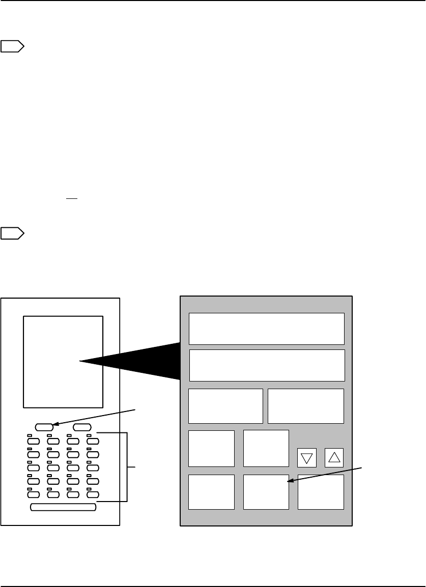
Press the Erase key on the keypad to enter the Erase Image mode (see Figure 4-9).
In this mode, any or all stored images can be erased.
To erase an individual image, press the Store key for that image. Once all the
desired images have been erased, press the Erase key again to exit the Erase
Image mode.
To erase all stored images, press the Erase All Images key on the Main Menu.
After erasing the images, the keypad automatically exits the Erase Image mode.
Note
When in Erase Image mode, the Erase All Images key is displayed in place of
the Format Menu key on the Main Menu.
Laser Imager Status:
MAIN MENU
Ready
Printed: 0
Imager
Menu
Keypad
Menu
Erase
All
Images
Erase Print
Copies: 1
Store
Keys
Erase
All
Images
Erase
Figure 4-9. Erasing Stored Images

DryView 8100 Laser Imager User Guide
4-14 8754020 2000 March Rev. B
DryView V2 Keypad Error Message Table
The following table lists all the DryView V2 Keypad error messages. (It does not
include status or action messages.) For each error message, perform the operator
action listed in the table next to the message. If the listed action does not clear the
error message, call for service.
Table 4-1. DryView V2 Keypad Error Messages
Message Operator Action
Laser Imager Status: Off-line Refer to the message on the Local Panel for a
di b Th l k thi
Printer Feed Error. Remove
Jam
corresponding error number. Then look up this
number in the error message table in Section 6 of
this manual Follow the instructions for resolving
Supply Magazine Failed
to Close
thi
s manua
l
.
F
o
ll
ow
th
e
i
ns
t
ruc
ti
ons
f
or reso
l
v
i
ng
the problem.
Supply Magazine Failed
to Open
Supply Magazine is Empty The film cartridge is empty. Load a new cartridge.
Supply Magazine is Missing There is no film cartridge in the machine. Load
one.
Troubleshooting
5-1
2000 March Rev. B 8754020
Troubleshooting
Operator Troubleshooting
Operators occasionally have to clear film jams in the imager or correct other simple
problems. If more serious malfunctions occur, operators must call a trained Kodak
service technician (see page 5-18).
To help operators monitor imager operation and identify problems, the imager
displays status and error messages. The following paragraphs describe these error
messages and list corrective actions the operator should take.
Local Panel Message Types
The Local Panel displays two types of messages, as described below.
S04 Stopped = 125
P145 Media Type Err
Status Line
Message Line
Scroll Indicator for Lists
Sheets
remaining
in Cartridge
Note
A scroll icon at the beginning of the message line indicates that more
information (above or below the line) is available. Press the Local Panel = or O
key to display another line of information.
Status Information
Status messages (see Table 5-1) are strictly informational and require no operator
action.
Error Messages or Notices
Error messages (see Table 5-2) indicate an error condition within the imager. In
some cases, error messages can be cleared by operator action, but in many cases a
service call will be required. Notices are brief messages identifying special print
requests (for example, calibration prints).

DryView 8100 Laser Imager User Guide
5-2 8754020 2000 March Rev. B
Note
The DryView 8100 Laser Imager displays a Local Panel message (P550) when
preventive maintenance and cleaning are recommended. Preventive
maintenance and cleaning ensure optimum performance of the imager. This
message will not interfere with normal operation. The intent of the message is
to allow the operator to schedule a convenient time to have preventive
maintenance and cleaning performed by a certified technician.
Note
For DryView V2 Keypad error messages, see Section 4.
Local Panel Status Messages
Table 5-1. Local Panel Status Messages
Status
Code Local Panel
Message Explanation
S00 Self Test The imager is performing a start-up self test. Please
wait.
S01 Ready The imager is idle and available for printing images.
S02 Warming=# The imager is warming up. Please wait for Ready
message. (# = the number of minutes remaining until
the imager will be ready to print.) The user can
acquire but not print during the warmup period.
S04 Stopped An error condition has caused the imager to stop.
See error message on line 2 of the display.
S11 Printing The imager is printing an image.
S12 Calibrate The imager is printing a calibration print.
The user can acquire and queue prints but the
calibration film will be printed first.
S13 Contrast The imager is printing a contrast test print.
The user can acquire and queue prints, but the
contrast test film will be printed first.
S14 Density The imager is printing a density test print.
The user can acquire and queue prints, but the
density test film will be printed first.

Troubleshooting
5-3
2000 March Rev. B 8754020
Status
Code Explanation
Local Panel
Message
S16 Wait 1. The imager is completing films in process before
unlatching the front door or,
2. There is an error condition. See error message on
line 2 of the display.
The user can continue to acquire and queue prints,
but the imager will not print until the condition has
been corrected.
S21 Door Open The front door is open.
The user can continue to acquire and queue prints,
but the imager will not print until the door has been
closed.
S22 Hood Open The upper hood is open.
The user can continue to acquire and queue prints,
but the imager will not print until the hood has been
closed.
S23 Doors Open The front door and upper hood are both open.
The user can continue to acquire and queue prints,
but the imager will not print until the door and hood
have been closed.
S24 Crtg Openg The imager is opening the film cartridge after the
front door has been closed.
The user can acquire and queue prints, but the
imager will not print until the cartridge is fully open.
S25 Crtg Clsng The imager is closing the film cartridge before
unlatching the front door.
The user can continue to acquire and queue prints,
but the imager will not print until the front door is
closed and the cartridge reopened.

DryView 8100 Laser Imager User Guide
5-4 8754020 2000 March Rev. B
Local Panel Error Messages
The following table lists the error messages displayed on the Local Panel. When an
error message is displayed, perform the operator action listed in the table for that
message. If this action does not clear the error message, call for service. When you
make a service call, be prepared to give the error message and message number to
the call taker (see page 5-18).
Note
In the table below the action “Cycle power” means to turn the imager Power
Switch off, wait 5 seconds, and then turn the switch on. If cycling power does
not clear the error, a service call is usually required.
Table 5-2. Local Panel Error Messages
Message
Number Message
Displayed Message Details/
Operator Action
P116 Pickup Fail The film pickup arm is unable to pick up film from the
film cartridge. Try printing again. If the error recurs:
See Film Pickup Problems in Area 1 on page
5-11.
P118 Elevator Fail The cartridge elevator did not return to its home
position after the door was closed.
Cycle power.
P119 Feed Err Area 2 Film is stalled in the feed area.
See Removing film Jams from Area 2 on page
5-12.
P121 Printer Error The imager is unable to print due to system
problems.
Cycle power.
P123 Printer Error The imager is unable to print due to system
problems.
Cycle power.
P132 No Crtg There is no film cartridge in the imager.
Load a film cartridge.
P133 Media Low Film cartridge contains less than 20 sheets.
Be ready to load a new film cartridge.

Troubleshooting
5-5
2000 March Rev. B 8754020
Message
Number Message Details/
Operator Action
Message
Displayed
P134 Crtg Empty The film cartridge is empty.
Insert a new film cartridge.
P137 Open Door Req The front door will not open because the imager is
printing.
Wait until S25 (cartridge closing) is displayed.
P138 Press Open 5S
(This message
alternates with
P177.)
The front door does not unlatch because the film
cartridge would not close or the elevator would not
lower.
Hold down the Open Door key on the Local Panel
for 5 seconds to force the front door open. Clear the
film jam or other error condition and manually close
the film cartridge. The top few sheets in the film
cartridge will be exposed.
P139 Bad Barcode The imager is unable to read the barcode on the
bottom of the film cartridge.
Try a different film cartridge.
P145 Media Type Err A reading of the barcode on the cartridge indicates
that the cartridge contains the wrong type of film.
Replace the cartridge with one containing the correct
type of film.
P146 Media Size Err A reading of the barcode on the cartridge indicates
that the cartridge contains film of the wrong size.
Replace the cartridge with one containing the correct
size film.
P149 Wait FilmModel The system is calculating film descriptive data from
the barcode data on the film cartridge.
Wait until the calculation is complete.
P154 Disk Maint The system is operating normally. A file system
problem is being corrected by recovery from a recent
backup. DO NOT cycle power while this message is
displayed. If power is cycled, the recovery will have
to start over from the beginning.

DryView 8100 Laser Imager User Guide
5-6 8754020 2000 March Rev. B
Message
Number Message Details/
Operator Action
Message
Displayed
P164 Jam–Area 3 Film is stalled in the exposure area.
See Removing Film Jams from Area 3 on page
5-13.
P165 Jam–Area 3 Film is stalled between the exposure area and the
processor.
See Removing Film Jams from Area 3 on page
5-13.
P169 Jam–Area 3 Film has stalled exiting the exposure area.
See Removing Film Jams from Area 3 on page
5-13.
P176 Crtg Open Err The imager could not open the film cartridge.
Press the Open Door key on the local Panel to open
the front door. Make sure that the cartridge is
installed correctly (not backward). Close the door
and try again. If the error recurs, call for service.
P177 Crtg Close Err
(This message
alternates with
P138.)
The imager could not close the film cartridge.
See Film Pickup Problems in Area 1 on page
5-11.
P202 Override Swtch The Service Override switch is ON. The imager
cannot expose film. (This switch is used only by
service technicians.)
Call for service.
P208 Door Fail Open The front door does not open.
Hold down the Open Door key on the Local Panel
for 5 seconds to force the front door open.
P506 Printer Error The imager is unable to print because of processor
problems.
Cycle power.
P509 Printer Error The imager is unable to print due to a system
problem.
Cycle power.

Troubleshooting
5-7
2000 March Rev. B 8754020
Message
Number Message Details/
Operator Action
Message
Displayed
P512 Calibrate Req The user has requested a calibration test film or the
imager has initiated an automatic calibration test
film.
P513 Contrast Req The user has requested a contrast test film.
P514 Density Req The user has requested a density test print.
P515 Calibrate Fail The calibration print failed. Request another
calibration.
If the error recurs, cycle power.
P542 Jam–Area 4 Film is stalled in the processor.
See Removing Film Jams from Area 4 on page
5-14.
P543 Jam–Area 5 Film is stalled between the processor and the
densitometer.
See Removing Film Jams from Area 5 on page
5-16.
P544 Jam–Area 5 Film is stalled between the densitometer and the exit
tray.
See Removing Film Jams from Area 5 on page
5-16.
P550 Cleaning
Recmd The imager is due for cleaning. Schedule a service
call.
P551 Printer Error The imager is unable to print because the processor
heater did not warm up.
Note P number and call for service.
P554 Printer Error The imager is unable to print. The processor heater
is shut down because temperature was too high.
Cycle power.
P561 Manual Mode The imager is operating in “manual” mode, without
Automatic Image Quality Control.
P601
through
P606
Printer Error The imager is unable to print due to a system
problem.
Note P number and call for service.

DryView 8100 Laser Imager User Guide
5-8 8754020 2000 March Rev. B
Message
Number Message Details/
Operator Action
Message
Displayed
P621 Printer Error The imager has detected that a film parameter file is
missing.
Call for service.
P622 Printer Error The imager is unable to print due to a system
problem.
Request a calibration print via the Local Panel.
P623 Printer Error The imager is unable to print due to a system
problem.
Note P number and call for service.
P624 Calibrate Fail The imager is unable to print because of print
density problems.
Try a new film cartridge. If the problem remains, call
for service. (Manual mode is NOT usable with this
error.)
P631 Calibrate Fail The Dmin specification was not met on a calibration
print.
Try a new film cartridge. If the problem remains, call
for service. Before service arrives, you can choose
to operate in manual mode. (See page 3-5.)
P632 Calibrate Fail The Dmax specification was not met on a calibration
print.
Try a new film cartridge. If the problem remains, call for
service. Before service arrives, you can choose to
operate in manual mode. (See page 3-5.)
P640 Optics Fail The imager is unable to print due to an optics
problem.
Cycle power.
P910 IMS Down The Image Management System is not
communicating.
Cycle power.
P912 IMS XFR Parity A parity error has been detected in the data
transferred from the Image Management System.
Cycle power.

Troubleshooting
5-9
2000 March Rev. B 8754020
Message
Number Message Details/
Operator Action
Message
Displayed
P913 IMS XFR Count Either too little or too much data has been
transferred from the Image Management System.
Cycle power.
P920 Printer Error The MCS Board failed its power-up self-test.
Cycle power.
P921 Printer Error The Feeder Board failed its power-up self-test.
Cycle power.
P922 Printer Error The Barcode Reader Board failed its power-up
self-test.
Cycle power.
P923 Printer Error The Optics Board failed its power-up self-test.
Cycle power.
P924 Printer Error The Densitometer Board failed its power-up self-test.
Cycle power.
DryView 8100 Laser Imager User Guide
5-10 8754020 2000 March Rev. B
Film Drive Problems
Figure 5-1 shows the path that film travels through the imager after the operator
requests a print. The numbers in the illustration identify key areas on the path from
film pickup to exposure through development and exit onto the film tray:
Area 1 – Film pickup from the cartridge
Area 2 – Film feed into the exposure area
Area 3 – Film feed out of the exposure area
Area 4 – Film feed into the processor
Area 5 – Film feed out of the processor
Figure 5-1. Film Drive Path
Troubleshooting
5-11
2000 March Rev. B 8754020
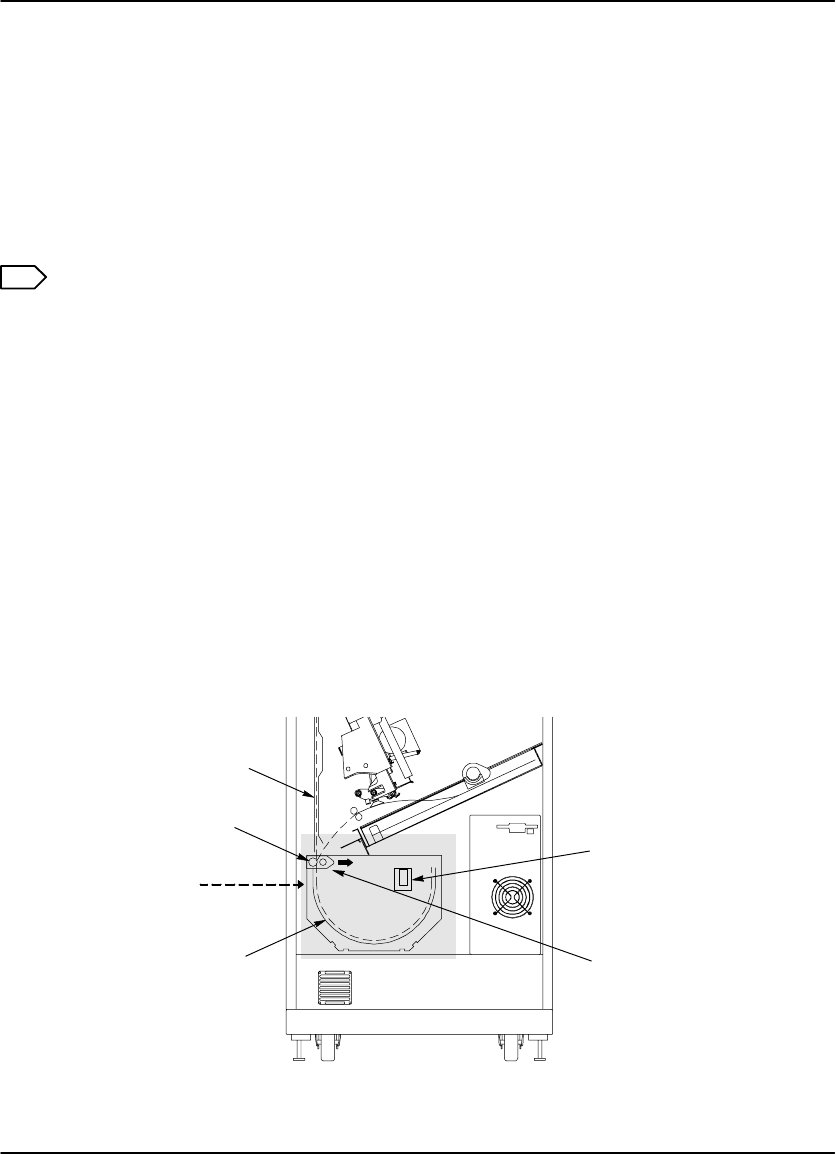
Film Pickup Problems in Area 1
Area 1 identifies the location where film is removed from the film cartridge and
positioned to be sent by drive rollers toward the exposure area (see Figure 5-2). If
the imager cannot properly pick up a sheet of film and position it for drive, error P116
is declared. P177 (Cartridge Close Error) also relates to Area 1.
Note
When problems occur in Area 1, the film cartridge is left open. When you open
the front door, the top sheets of film in the cartridge will be exposed. Before
opening the door, make the room as dark as possible to minimize exposure.
1. Press and hold in the Open Door key on the Local Panel for 5 seconds to unlock
the front door.
2. Open the front door and check the film pickup area. (There may be a film
cartridge problem.) If you cannot resolve the problem, call for service.
3. Turn the rollback knob counterclockwise to manually close the cartridge lid.
4. Close the front door.
Rollback
Knob
Area 1
8100–50L
Figure 5-2. Film Area 1
DryView 8100 Laser Imager User Guide
5-12 8754020 2000 March Rev. B
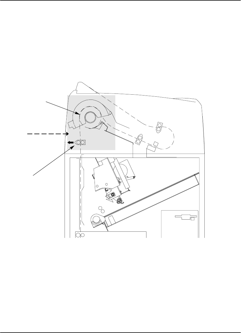
Removing Film Jams from Area 2
Area 2 in the imager includes the path between the film pickup assembly and the
exposure platen (see Figure 5-3).
Note
When jams occur in Area 2, the film cartridge is left open. When you open the
front door, the top sheets of film in the cartridge will be exposed. Before
opening the door, make the room as dark as possible to minimize exposure.
1. Press and hold in the Open Door key on the Local Panel for 5 seconds to unlock
the front door.
2. Open the front door and clear the film jam.
3. Turn the rollback knob counterclockwise to manually close the cartridge lid.
4. Close the front door.
Rollback
Knob
8100–116L
Area 2
Film Pickup
Assembly
Exposure
Platen
Figure 5-3. Jam Area 2
Troubleshooting
5-13
2000 March Rev. B 8754020
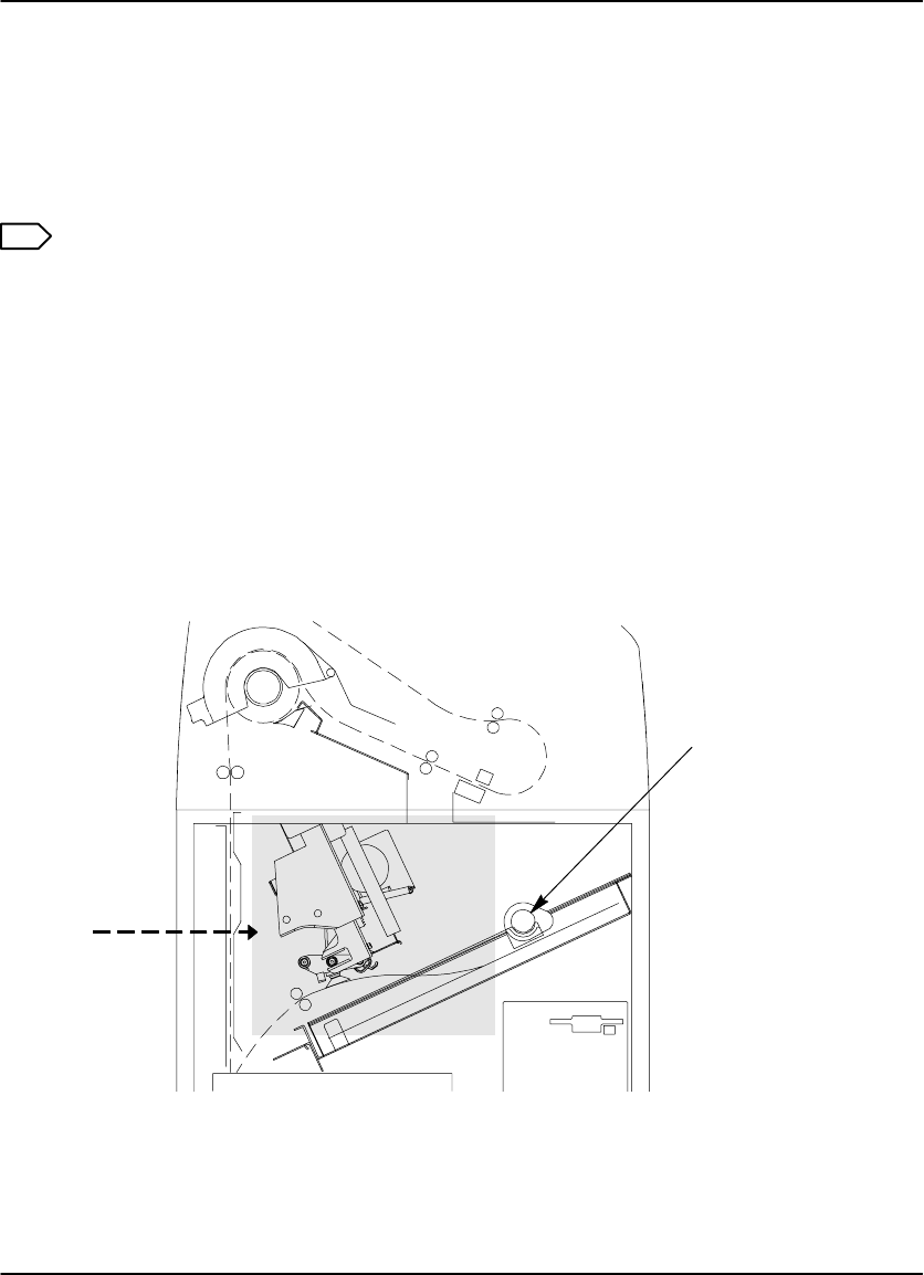
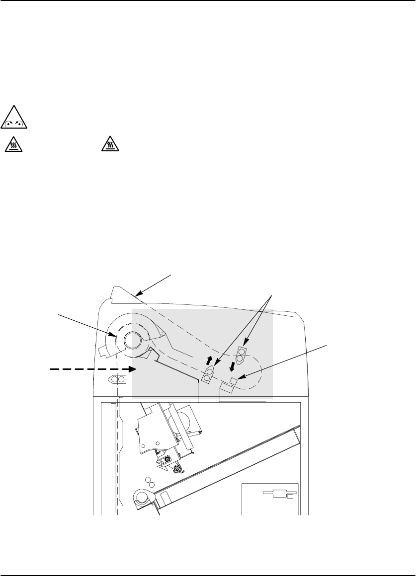
Removing Film Jams from Area 3
Area 3 includes the exposure platen (see Figure 5-4). Jams in this area occur as film
is entering the platen before exposure, or as film is leaving the platen after
exposure. In rare cases, film may stall in the transport area above the platen.
1. Press the Open Door key on the Local Panel to unlock the front door. (The
status message S25 Crtg Clsng will display, and the imager will close the
cartridge and unlock the front door.)
Note
If the film cartridge does not close, you will have to press and hold the Door
Open key for 5 seconds to unlock the front door. Be aware that when you open
the door, the top sheets of film in the cartridge will be exposed. Before opening
the door, make the room as dark as possible to minimize exposure.
2. Open the front door and clear the jammed film, if it is accessible.
3. If the film is not accessible:
a. Open the platen door by sliding the door latch to the left and pulling out.
b. Clear the film from inside the platen. If film is caught in the feed rollers (see
Figure 5-4), pull the green thumb tab to the right to open the rollers and free
the film.
c. After clearing the jam, close the platen door.
4. Close the front door.
Platen Door
Latch
8100–51L
Area 3
NOTE:
Film could jam in
this area also.
Exposure
Platen
Platen Feed
Rollers
Pull green thumb
tab to the right to
free film jammed
in rollers.
Figure 5-4. Jam Area 3
DryView 8100 Laser Imager User Guide
5-14 8754020 2000 March Rev. B
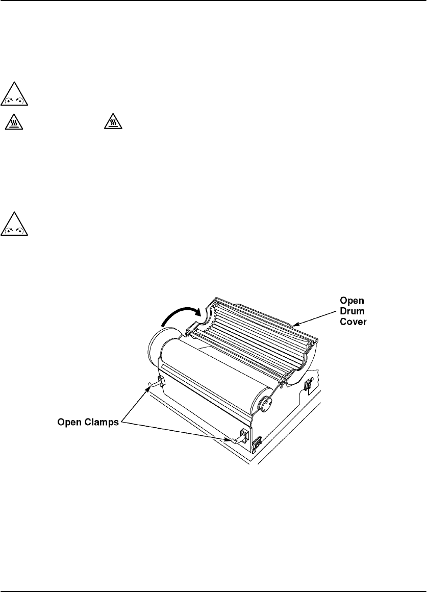
Removing Film Jams from Area 4
Area 4 includes the film processor.
1. Open the upper hood.
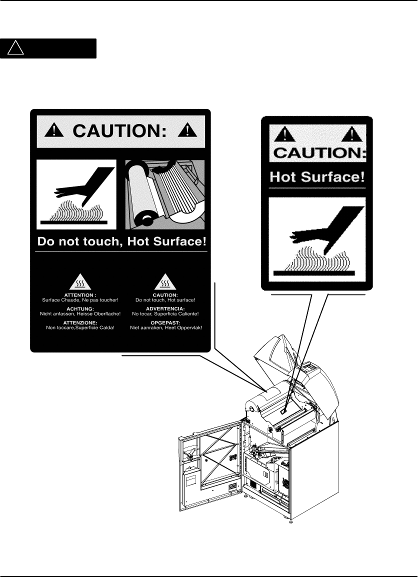
! Caution
Hot Surface
Drum and rollers inside the processor are hot. Exercise caution when
removing jammed film from the processor.
2. Release the two clamps at the left of the processor and open the drum cover
(see Figure 5-5).
! Caution
To prevent damage to the surface of the processor drum, do not use any type
of tool to remove jammed film.
Figure 5-5. Opening the Drum Cover
Troubleshooting
5-15
2000 March Rev. B 8754020
3. Clear the jammed film from the processor area. (There may be more than one
sheet.) If film is jammed in the drive rollers (see Figure 5-6), pull the green thumb
tab to the left to open the rollers and free the film.
4. Close the drum cover and secure it with the two clamps.
5. Close the upper hood. (The processor will have to warm to operating
temperature before printing can occur again.)
8100–53L
Area 4
Processor
Drum
Pull green thumb
tab to the left to
free film jammed
in rollers.
Figure 5-6. Jam Area 4
DryView 8100 Laser Imager User Guide
5-16 8754020 2000 March Rev. B
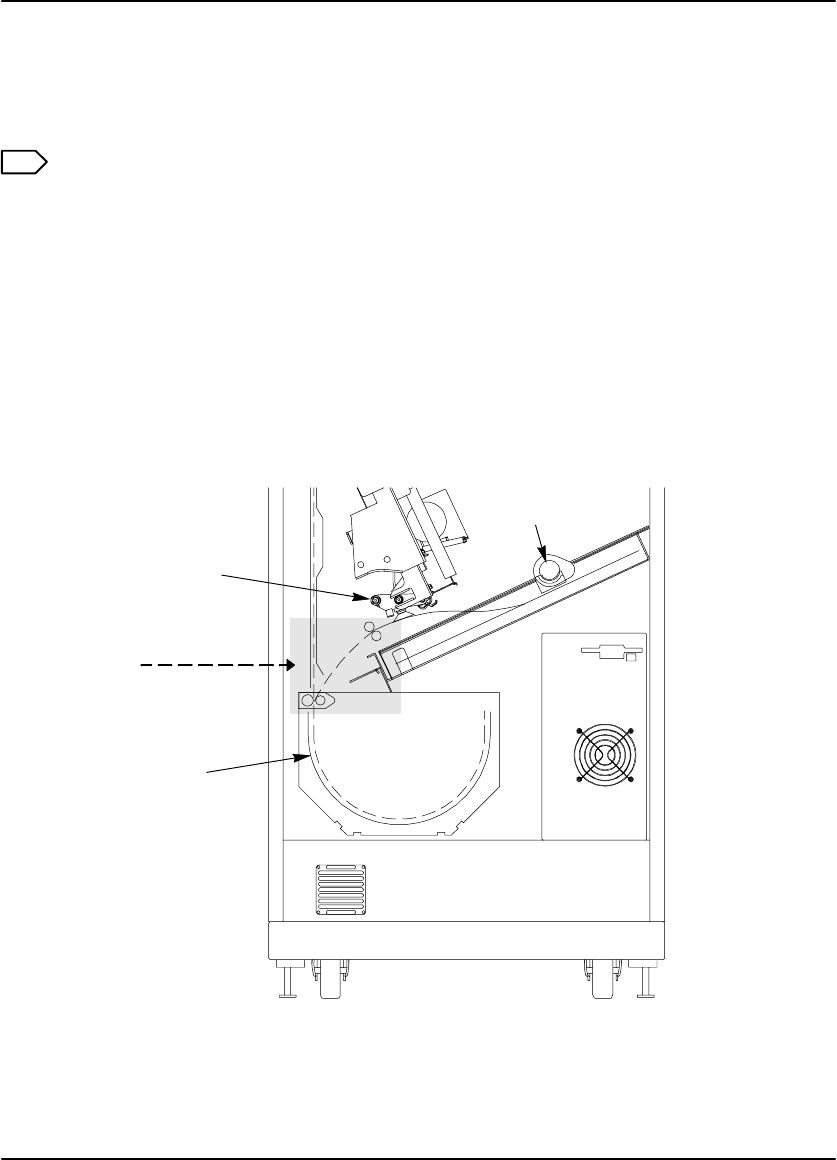
Removing Film Jams from Area 5
Area 5 consists of the components between the processor drum and the film exit
tray (see Figure 5-7). Jams can occur in this area between the drum and the
densitometer, or in the densitometer.
1. Open the upper hood.
! Caution
Hot Surface
Drum and rollers inside the processor are hot. Exercise caution when working
in the drum area.
2. Clear the jammed film. (There may be more than one sheet.) If film is jammed in
the drive rollers (see Figure 5-7), use the green thumb tab to open the rollers and
free the film.
3. Close the upper hood.
8100–55L
Area 5
Processor
Drum
Densitometer
Exit Tray Pull green thumb tab in
direction shown to free
film jammed in rollers.
Figure 5-7. Jam Area 5
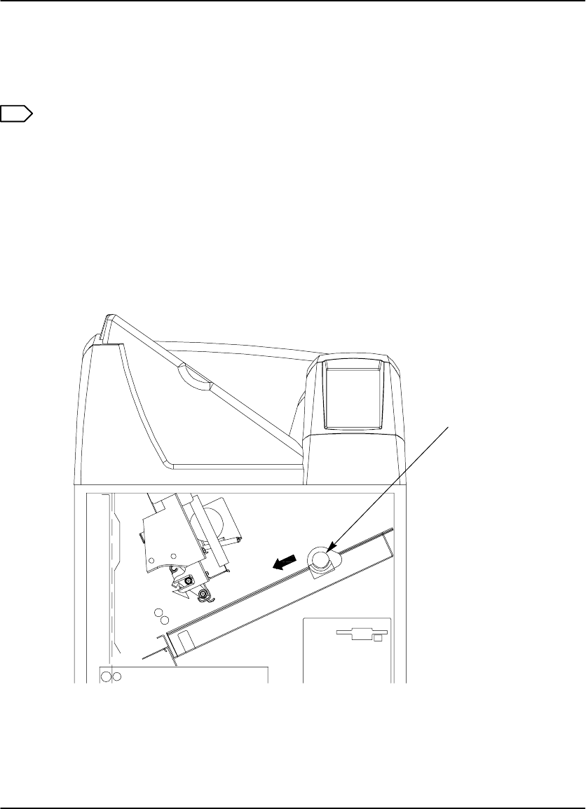
Troubleshooting
5-17
2000 March Rev. B 8754020
Manually Closing the Film Cartridge
The imager automatically closes the film cartridge when the Door Open key is
pressed. If the imager is unable to close the cartridge, a P177 error displays.
Note
If the front door is opened when the film cartridge is open, the top sheets of film
in the cartridge are exposed. Make the room as dark as possible to minimize
exposure.
1. Press and hold the Open Door key on the Local Panel for 5 seconds to unlock
and open the front door.
2. Clear any films that may be jammed in the film cartridge area.
3. Turn the rollback knob (see Figure 5-8) counterclockwise to close the cartridge.
Rollback
Knob
8100–54L
Figure 5-8. Manually Closing the Film Cartridge
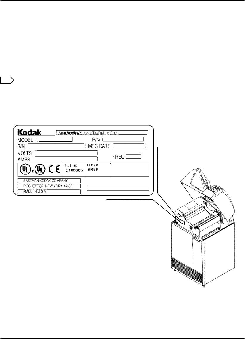
DryView 8100 Laser Imager User Guide
5-18 8754020 2000 March Rev. B
Calling for Support
When you have tried to repair the machine, but realize that you need help, it is time
to call for service. Before you call, have the following information ready:
Model Number: 8100
Serial Number: For serial number location, see Figure 5-9.
Phone for Service: 1-800-328-7754, Option 1
Note
For general information about Kodak Health Imaging Products, call
1-800-328-2910, Option 3.
Figure 5-9. Serial Number Location

Specifications
6-1
2000 March Rev. B 8754020
Specifications
Dimensions
Height: 1168 mm (46 in.) – Top cover closed
1581 mm (62–1/4 in.) – Top cover open
Width: 635 mm (25 in.)
Depth: 661 mm (26 in.) – Front door closed
1245 mm (49 in.) – Front door open
Weight: 188 kg (414 lbs.)
Electrical
Voltage: 100 V AC " 10%, 50/60 Hz " 3
120 V AC " 10%, 50 Hz " 3
230 V AC " 10%, 50 Hz " 3
Current Draw: Less than 12 Amperes at 100 V AC input
Less than 10 Amperes at 120 V AC input
Power Consumption: 700 Watts (maximum)
Operating Environment
Temperature: 15° to 35°C (59° to 95°F)
Humidity: 15% to 85% RH, Noncondensing
Magnetic Field: v 50 Gauss
Environmental Effects
Heat Dissipation: 3000 BTU/Hr (average)
Acoustical Noise: Less than 55 dB at one meter (70 dB momentarily)
Less than 80 dB, non–repetitive tasks such as door
open/close

DryView 8100 Laser Imager User Guide
6-2 8754020 2000 March Rev. B
Storage Environment
Temperature: –35° to 60°C (–31° to 140°F)
Humidity: 10% to 90% RH, Noncondensing
Film Size
The 8100 will process 14 inch by 17 inch DryView Laser Imaging Film.
Film Throughput
55 films per hour (assuming images of 1024 by 1024 pixels and a direct connect
input).
Host Control
RS232 or RS422 connection to imager.
DryView V2 Keypad
Available image formats include 1:1, 2:1, 4:1, 6:1, 9:1, 12:1, 15:1, 16:1, and
20:1.
Images can be acquired and stored in random or sequential order.
Can be located up to 3 meters (10 feet) from imager when connected directly.
Can be located up to 60 meters (198 feet) from imager if a UKEIB interface
box is used.
Agency Compliance
See the Safety, EMC, and CE Marking Compliance paragraphs at the beginning of
this manual.
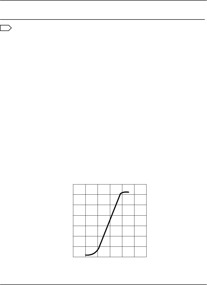
Technical Information
7-1
2000 March Rev. B 8754020
Technical Information
Note
The information in this section relates to the characteristics of DryView Laser
Imaging Film, not to the operation of the DryView 8100 Laser Imager.
General Description
DryView Laser Imaging Film is a high-resolution, infrared-sensitive,
photothermographic film designed specifically for the new family of DryView Laser
Imaging Systems.
This new film delivers the same diagnostic image quality you get with your current
silver halide laser films – but it requires no “wet” chemistry, no “wet” film processors,
and no darkroom procedures. This means there is no need for special plumbing, wet
chemistry disposal procedures, or modifications to your facility. This new film is
packaged in daylight load packages and is available in 14 inch by 17 inch size. It is
available in blue or clear, 7 mil polyester base.
Spectral Sensitivity
DryView Laser Imaging Film is infrared sensitive and has been sensitized to the
infrared laser diode of DryView Laser Imaging Systems. When handled according
to instructions on the film package, safelights are not needed. It is not
recommended, but if you remove undeveloped film from the daylight load package,
you will need a darkroom setting and a green safelight.
Sensitometric Characteristics
RELATIVE LOG EXPOSURE
0 0.5 1 1.5 2 2.5 3
0
0.5
1
1.5
2
2.5
3
3.5
DENSITY

DryView 8100 Laser Imager User Guide
7-2 8754020 2000 March Rev. B
Image Quality
DryView Laser Imaging Film delivers diagnostic-quality, continuous-tone images
along with sharp alphanumerics and optimum contrast. This high-quality silver-based
film provides radiologists with the same diagnostic information they are accustomed
to viewing – including the spatial resolution, contrast, and gray levels. Plus, because
it is a totally dry imaging process, there is no image quality variability due to “wet”
chemistry.
Automatic Image Quality Control
DryView Laser Imaging Film is system-matched for the unique Automatic Image
Quality Control (AIQC) technology. This fully automated system, which is a standard
feature of DryView Laser Imaging Systems, is designed to ensure that contrast,
density, and other image quality parameters meet preset user preferences,
film-to-film, lot-to-lot.
Barcode information on each film cartridge allows the DryView 8100 Laser Imager to
automatically determine film type, the number of sheets remaining, and the film
manufacturing lot. The AIQC uses this information to automatically calibrate the
imager’s electronics and optimize image quality without operator intervention.
The AIQC also reads a special density patch printed on each 14 inch by 17 inch
sheet of DryView Laser Imaging Film as it passes through a built-in densitometer.
Slight density variations are corrected automatically.
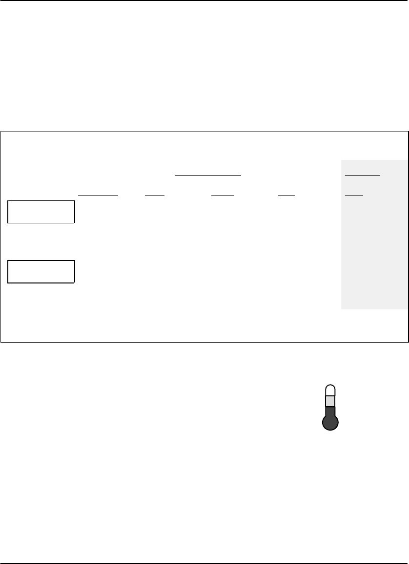
77°F
41°F
25°C
5°C
TEMP
Technical Information
7-3
2000 March Rev. B 8754020
Less Impact on the Environment
Disposal regulations and procedures for “wet” processing chemistry are
time-consuming and expensive. And even with the most exacting procedures, the
potential exists to discharge hazardous materials into the environment.
Tests show that DryView Laser Imaging Film is not considered hazardous to the
environment. As a result, you can develop, recycle, and dispose of films with less
impact on the environment than if you were using wet developed silver halide films.
DryView Laser Imaging Film
Environmental Regulations Comparison
Wet Silver Halide DryView
Developer Fixer Wash Film Film
Product
Regulation
OSHA MSDS
DOT
Use Permits
Required
Hazardous
Local
Required
Hazardous
Local
Not Required
No Limits
None
Not Required
No Limits
None
Provided
No Limits
None
Disposal *
Regulation
EPA
DOT
Hazardous
Hazardous
Hazardous
Hazardous
No
No
No
No
No
No
Note: There is no SUPERFUND liability with DryView Laser Imaging Film.
* State and local laws vary. Consult appropriate regulations or authorities prior to disposal.
Storage and Handling of Undeveloped Film
As with other laser imaging films, to achieve consistent
results up to the expiration date indicated on the film
package, DryView Laser Imaging Film must be stored
in a cool, dry place (41°F/5°C to 77°F/25°C) and
protected from radiation and chemistry fumes.
The film can also withstand short-term temperature spikes (up to 95°F/35°C for
several hours) during transit without any significant effect on film quality or
performance. Transit temperatures above 95°F/35°C will gradually diminish shelf life.
If the Automatic Image Quality Control system (AIQC) encounters film that has been
damaged by improper handling, it will automatically alert system operators before
the film is developed.

DryView 8100 Laser Imager User Guide
7-4 8754020 2000 March Rev. B
Handling of Developed Film
As with other photographic films or data storage materials, the handling of DryView
Laser Imaging Film requires reasonable care. Spills, humidity, and other moisture
typically have no significant effect on developed films. Prolonged exposure to
intense light or excessive heat (130°F/54.4°C for more than 3 hours) may cause
some gradual darkening of images. Leaving films in vehicles in hot climates for
extended periods of time is not recommended.
Under typical working conditions, DryView Laser Imaging Film will maintain
diagnostic quality for over 30 years. For best results, store film in sleeves when not
being reviewed. DryView Laser Imaging Film can be left on a light box for more than
24 hours; in extreme cases in which light boxes are exceptionally hot (120°F/49°C),
we recommend removing them prior to 8 hours of continuous exposure.
Care should be taken when using spotlight viewing for more than 30 seconds,
because temperatures near the light source may exceed 180°F/82.2°C. Use in slide
projectors is not recommended due to the high temperatures generally found in
these devices.
With the new DryView technology, a small amount of final development occurs when
the film exits the DryView Laser Imager and is initially exposed to ambient or view
box lighting. This is virtually undetectable and has no effect on image quality (i.e.,
typically 0.02 change in density). This small density increase is uniform and
permanent upon full exposure of the film under normal handling conditions (i.e.,
room light or view box).
Archivability of Developed Film
DryView Laser Imaging Film is fully archivable for more than 100 years when stored
at American National Standards Institute (ANSI) recommended storage conditions
(77°F/25°C). Developed films may be stored at higher temperatures, but that may
affect archivability. For example, storing films at a constant elevated temperature of
90°F/32.2°C may reduce archivability to 30 years.
Exposure to Moisture
While moisture can damage traditional wet processed silver halide films, DryView
Laser Imaging Films typically withstand humidity, spills, and other forms of water
without any significant effect on image quality or film integrity. If needed, films can be
cleaned with a clean, damp cloth.

Technical Information
7-5
2000 March Rev. B 8754020
Odor Dissipation
The “wet” chemistry associated with the development of silver halide film creates
strong, unpleasant odors. By eliminating “wet” chemistry, DryView technology
eliminates virtually all of these odors. While some low-level odors are produced
during the development process, they pose no known adverse health risks.
Processing odor levels are further reduced by a non-hazardous, recyclable filter in
DryView Laser Imaging Systems. This filter traps most low-level odors and prevents
them from dissipating into the work environment. To help maintain optimum
performance, the filter requires periodic replacement as specified in the DryView
Laser Imager User’s Manual. Unlike silver halide systems, DryView Laser Imagers
require no special venting.
Heat Dissipation
DryView Laser Imaging Systems use controlled heat to develop DryView Laser
Imaging Films. The heat has virtually no effect on the air temperature of the work
area. The amount of heat dissipated into an area during a day is typically less than
the heat generated by four 100-watt light bulbs.
Film Recycling
According to the Environmental Protection Agency (EPA) standards, DryView Laser
Imaging Film is not considered hazardous – so unlike typical “wet” films, these films
require no special disposal procedures. But they do contain silver and polyester that
may be recovered by using one of several recycling processes.
If you are interested in recycling and silver recovery, Kodak can provide your local
recyclers with the information they need to get started. In some countries, national
contracts have been established with recycling firms. Call your local Kodak sales
representative for more information about these contracts.

DryView 8100 Laser Imager User Guide
7-6 8754020 2000 March Rev. B
IMPORTANT NOTICE TO PURCHASER
Kodak warrants that Kodak hardware products will be free from defects in parts,
material, and manufacture for the period of one (1) year from the date of installation.
For defects occurring during the warranty period and about which Kodak has
received notice during the warranty period, Kodak will provide Customer with free
replacement parts and labor to replace warranty-covered items. THIS WARRANTY
IS MADE IN LIEU OF ALL OTHER PRODUCT WARRANTIES, EXPRESS OR
IMPLIED, INCLUDING THE IMPLIED WARRANTIES OF MERCHANTABILITY AND
FITNESS FOR A PARTICULAR PURPOSE AND THOSE ARISING FROM A
COURSE OF DEALING OR USAGE OF TRADE. This express warranty does not
apply to expendable parts; defects or damage due to neglect, misuse, operator
error, improper installation or alteration of Kodak hardware products or operation of
Kodak hardware products out of specification. EXCEPT FOR THE EXCLUSIVE
REMEDY STATED ABOVE, KODAK IS NOT LIABLE FOR ANY DIRECT, INDIRECT,
INCIDENTAL, OR CONSEQUENTIAL DAMAGES, HOWEVER OCCURRING AND
REGARDLESS OF THE LEGAL THEORY ASSERTED, INCLUDING NEGLIGENCE
AND STRICT LIABILITY. Kodak shall in no event be liable for any of the following:
(a) the performance or non-performance of any network utilized by the Customer,
(b) the performance or non-performance of any third party equipment or software, or
(c) the impact of any Kodak product upon a network or third party equipment or
software.
Kodak and DryView are Trademarks of Eastman Kodak Company.