Eastman Kodak 870085007E2620 Kodak DryView 8700/8500 Laser Imager User Manual ug8700
Eastman Kodak Company Kodak DryView 8700/8500 Laser Imager ug8700
Contents
- 1. Draft user manual
- 2. draft user guide
Draft user manual
User Guide
Kodak DryView 8700/8500 Laser Imager
8599110
41-1202-0176-3
3/01 Rev. B
DRAFT
1
Warnings and Cautions
i
2001 March Rev. B 8599110
Warnings and Cautions for
Kodak DryView 8700/8500 Laser Imager
Safety Instructions
Read and understand all instructions before using.
!WARNING
This equipment is operated with hazardous voltage which can shock,
burn, or cause death.
Remove wall plug before servicing equipment. Never pull on cord to remove from
outlet. Grasp plug and pull to disconnect.
Do not operate equipment with a damaged power cord.
Do not use an extension cord to power this equipment.
Position the power cord so it will not be tripped over or pulled.
Connect this equipment to a grounded outlet.
Use only the power cord supplied with this equipment.
!WARNING
For Continued Protection against Fire, Replace Fuses with only the Same Type and
Fuse Rating.
!WARNING
This equipment contains moving parts that may be accessible to the user. Loose
clothing, jewelry, or long hair may cause minor personal injury or damage to the
equipment. Do not operate equipment with the covers open. Do not operate
equipment with any of the safety interlocks overridden.
!WARNING
This equipment is not contained in a sealed cabinet. Therefore, it must not be used
in locations where it can come in contact with liquids, including bodily fluids.
User Guide
ii 8599110 2001 March Rev. B
!CAUTION
Avoid Laser Beam
This equipment employs a 150 milliwatt laser. Laser radiation may be
present when the machine operates without panels or covers installed.
Use of controls or adjustments, or performance of procedures other than those
specified herein, may result in eye damage.
Covers shall be removed by authorized service personnel only.
!CAUTION
Do not substitute or modify any part of this equipment without approval of Eastman
Kodak Company.
!CAUTION
General External Cleaning: This equipment may be cleaned with a damp cloth
using water with mild detergent, or commercial electronic equipment cleaner.
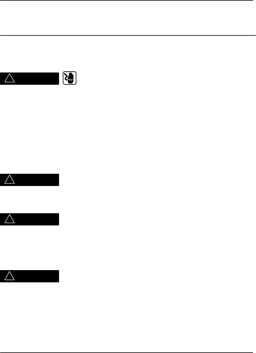
ATTENTION:
Surface Chaude. Ne pas toucher!
ACHTUNG:
Nicht anfassen. Heisse Oberflache!
ATTENZIONE:
Non toccare. Superficie Calda!
CAUTION:
Do not touch. Hot surface!
ADVERTENCIA:
No tocar. Superficia Caliente!
OPGEPAST:
Niet aanraken. Heet Oppervlak!
Do not touch, Hot Surface!
!CAUTION
U.S. Federal law restricts this device to the sale by, or on the order of, a licensed
health care practitioner.
Warnings and Cautions
iii
2001 March Rev. B 8599110
!CAUTION
This equipment is intended to connect to other medical devices. Only qualified
service personnel may perform installation and service maintenance. The laser in
the equipment is not a patient device. Therefore, the equipment must be installed no
closer than 1.83 meters from a patient bed or chair.
!CAUTION
Do not use in the presence of flammable anesthetics, oxygen or nitrous oxide. This
equipment does not have a gas–sealed electronics enclosure and could ignite any
flammable or explosive gases present in its environment.
!CAUTION
This equipment has been tested and found to comply with the limits for a Class B
digital device, pursuant to part 15 of the FCC rules. Those limits are designed to
provide reasonable protection against harmful interference in a residential
installation. This equipment generates, uses, and can radiate radio frequency
energy and, if not installed and used in accordance with the instructions, may cause
harmful interference to radio communications. However, there is no guarantee that
interference will not occur in a particular installation. If this equipment does cause
harmful interference to radio or television reception, which can be determined by
turning the equipment off and on, the user is encouraged to try to correct the
interference by one or more of the following measures:
Reorient or relocate the receiving antenna.
Increase the separation between the equipment and the receiver.
Connect the equipment into an outlet on a circuit different from that to which the
receiver is connected.
Consult the dealer or an experienced radio/TV technician for help.
FCC ID: PA4870085007E2620
User Guide
iv 8599110 2001 March Rev. B
Class 1 Laser
Laser de catégorie 1
Laser-Klasse 1
Laser di Classe 1
Klass 1 Laser
Front Left Rear
DANGER - Invisible Laser Radiation When Open.
Avoid Direct Exposure to Beam.
ATTENTION - Rayonnement Laser Invisible En Cas
D’Ouverture. Exposition Dangereuse
Au Faisceau.
VORSICHT - Unsichtbare Laserstrahlung Wenn Abdeckung
Geöffnet. Nicht Dem Strahl Aussetzen.
VARNING - Osynlig Laserstrålning. Laserstråining När
Denna Del Ä Öppnad. Strålen Är Farlig.
Warnings and Cautions
v
2001 MarchRev.B8599110
W
a
r
n
i
n
g
s
a
n
d
C
a
u
t
i
o
n
s
forExternal Interface BoxAccessories
Readand understand all instructionsbeforeusing.
Classifications
ULClassified
FileNumberE183646
Control Number9R46
MedicalEquipment
UL 2601-1CAN/CSA No.601.1
!Classified byUnderwritersLaboratoriesInc.ÒWithRespect toElectricShock,
Fire,Casualtyand Medical HazardsonlyinAccordancewithUL 2601-1,CAN/CSA
C22.2No.601.1 and IEC601.1.
!WARNING
This equipmentisoperatedwith hazardous voltagewhichcanshock,
burn orcause death.
¯Removewall plug beforeservicing equipment. Neverpull on cordtoremovefrom
outlet. Grasp plug and pull to disconnect.
¯Do notoperate equipmentwith a damaged powercord.
¯Do notuse an extension cordto powerthisequipment.
¯Use onlythe powercordsupplied withthisequipment.
¯Position the powercordsoitwill notbe tripped overorpulled.
¯Connect thisequipment toagrounded outlet.
¯Do notplace a portablemultiple--socketoutlet(powerstrip)on the floor.Mount
the powerstriponawall oron the underside ofatable.
UserGuide
vi8599110 2001 MarchRev.B
!WARNING
Thisequipmentcontainsmoving partsthatmaybe accessibletothe user.Loose
clothing,jewelryorlong hair may causeminorpersonal injuryordamage tothe
equipment. Do notoperate equipmentwiththe coversopen.Do notoperate
equipmentwith anyof the safetyinterlocks overridden..
!WARNING
Thisequipmentisnotcontained inasealed cabinet. Therefore,itmustnotbe used
inlocationswhereitcan comeincontactwithliquids,including bodilyfluids.
!WARNING
ForContinued Protection againstFire,ReplaceFuseswith onlythe SameType and
FuseRating.
!CAUTION
Do notsubstitute or modifyanypartof thisequipmentwithoutapprovalofEastman
KodakCompany.
!CAUTION
GeneralExternalCleaning:Thisequipmentmaybe cleaned with a dampcloth
using waterwithmild detergent, orcommercialelectronicequipmentcleaner.
Type B Applied Part
!CAUTION
Do notuseinthe presence of flammable anesthetics,oxygen ornitrousoxide.This
equipmentdoesnothave a gas--sealed electronics enclosure and couldignite any
flammable orexplosive gasespresentinitsenvironment.
!CAUTION
Thisequipmentisintended toconnect to other medicaldevices. Onlyqualified
service personnelmayperform installation and servicemaintenance.
!CAUTION
U.S.Federal lawrestrictsthisdevicetothe sale by,oron the orderof, alicensed
healthcare practitioner.
Warnings and Cautions
vii
2001 MarchRev.B8599110
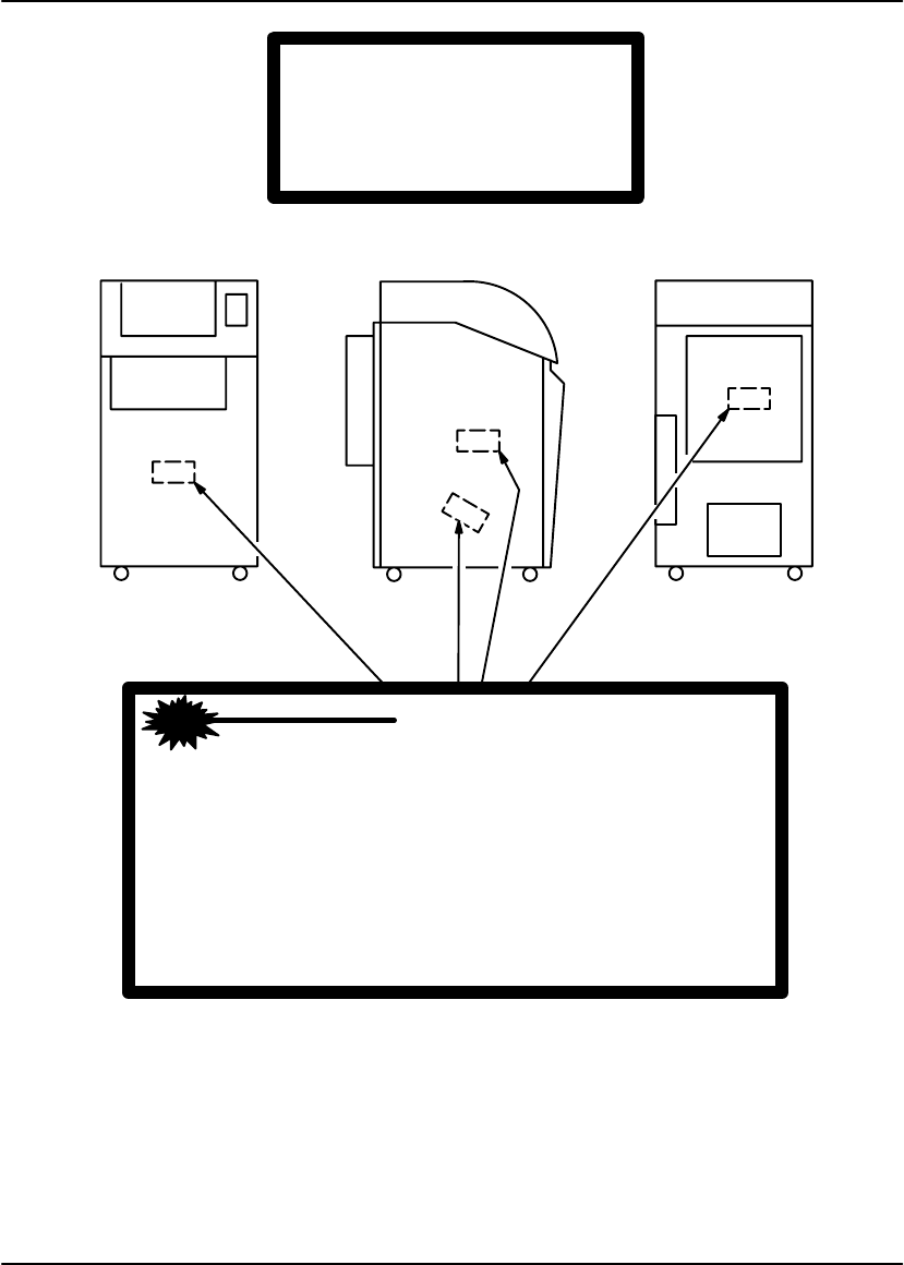
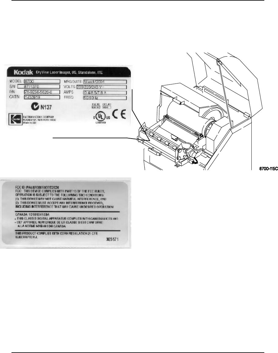
Readand understand all instructionsbeforeusing.
Label located on back ofmachine.

UserGuide
viii 8599110 2001 MarchRev.B
BLANK PAGE

Agency, Regulatory and CE Marking Compliance
ix
2001 March Rev. B 8599110
Agency, Regulatory and CE Marking Compliance
This equipment has been tested for and complies with the following Safety and
Emission Standards. Certificates of Compliance and Declarations of Conformity
have been issued as shown below.
Safety:
Canada:
C22.2 NO 950-95–CAN/CSA Safety for Information Technology Equipment,
Including Electrical Business Equipment
C22.2 NO 601.1–M90–CAN/CSA Medical Electrical Equipment – Part 1:
General Requirements for Safety
CSA–CS–03: Rules for Telecommunication Equipment
Europe:
EN60950: Safety of Information Technology Equipment, Including Electrical
Business Equipment (IEC 60950 : 1991, Modified) (Includes Amendment A1 and
A2: 1993)
EN60601–1–1: Medical electrical equipment – Part 1: General requirements for
safety – Section 1: Collateral standard: Safety requirements for medical electrical
systems
EN60825–1: Safety of laser products – Part 1: Equipment classification,
requirements and user’s guide
U.S.A.:
UL 1950: Safety of Information Technology Equipment, Including Electrical
Business Equipment DOD (Bi–National Standard) with UL 2601–1 Medical
Electrical Equipment, Part 1: General Requirements for Safety
21CFR1040.10 Class I: FDA CDRH Code of Federal Regulations Title 21,
Volume 8, Food and Drugs, Part 1040 Performance Standards For
Light–Emitting Products, Section 10 Laser Products
FDA Premarket Notification 510(K): Regulatory Requirements For Medical
Devices
47 CFR Part 68: FCC Rules for Telecommunication Equipment

User Guide
x8599110 2001 March Rev. B
Rest of World:
IEC 950: Safety of information technology equipment
IEC 60601–1–1: Medical electrical equipment – Part 1: General requirements for
safety – Section 1: Collateral standard: Safety requirements for medical electrical
systems
IEC 60825–1: Safety of laser products – Part 1: Equipment classification,
requirements and user’s guide
EMC:
Canada:
CAN/CSA–C108.6–M91 Class A: Limits and Methods of Measurement of
Electromagnetic Disturbance Characteristics of Industrial, Scientific and Medical
(ISM) Radio–Frequency Equipment
Europe:
EN55022 (CISPR 22) Class B Group 1: Limits and Methods of Measurement of
Radio Interference Characteristics of Information Technology Equipment
EN300330: 1999 European Telecommunication Standard, Sections 7.2 and 7.4
Emission Requirements
EN300683: 1997 European Telecommunication Standard, Section 8 Emission
Requirements and Immunity Requirements
EN61000–3–2 (IEC 1000–3–2): 1995 Electromagnetic Compatibility (EMC) –
Part 3: Limits – Section 2: Limits for Harmonic Current Emissions (equipment
input current <= 16A per phase)
EN61000–3–3 (IEC 1000–3–3): 1995 Electromagnetic Compatibility (EMC) –
Part 3: Limits – Section 3: Limits for Voltage Flicker Emissions (equipment input
<– 16A per phase)
EN 61000–4–2 (IEC 1000–4–2): Electromagnetic Compatibility (EMC) – Part 4:
Testing and Measurement techniques – Section 2: Electrostatic Discharge
Immunity Test. Basic EMC Publication
EN 61000–4–3 (IEC 1000–4–3): Electromagnetic Compatibility (EMC) – Part 4:
Testing and Measurement Techniques – Section 3: Radiated, Radio–frequency,
Electromagnetic Field Immunity Test
EN 61000–4–4 (IEC 1000–4–4): Electromagnetic Compatibility (EMC) – Part 4:
Testing and Measurement techniques – Section 4: Electrical Fast Transient/Burst
Immunity Test. Basic EMC Publication

Agency, Regulatory and CE Marking Compliance
xi
2001 March Rev. B 8599110
EN 61000–4–5 (IEC 1000–4–5): Electromagnetic Compatibility (EMC) – Part 4:
Testing and Measurement Techniques – Section 5: Surge Immunity Test
EN 61000–4–6 (IEC 1000–4–6): Electromagnetic Compatibility (EMC) – Part 4:
Testing and Measurement Techniques – Section 6: Immunity to Conducted
Disturbances, Induced by Radio–Frequency Fields
EN61000–4–8 (IEC1000–4–8): Electromagnetic Compatibility (EMC) – Part 4:
Testing and Measurement Techniques – Section 8: Power Frequency Magnetic
Field
EN 61000–4–11 (IEC 1000–4–11): Electromagnetic Compatibility (EMC) –
Part 4: Testing and Measuring Techniques – Section 11: Voltage Dips, Short
Interruptions and Voltage Variations Immunity Tests
U.S.A.:
FCC Rules and Regulations, Title 47, Part 15, Subpart B, Class B: Radio
Frequency Devices: Unintentional Radiators; Part 15, Subpart C, Section 15.209
Radiated Emission Requirements
Rest of World:
CISPR 22 Class B Group 1: Limits and Methods of Measurement of Radio
Interference Characteristics of Information Technology Equipment
Directives:
EU:
73/23/EEC Council Directive on the Harmonization of the Laws of Member
States Relating to Electrical Equipment Designed for Use within Certain Voltage
Limits
89/336/EEC Council Directive on the Approximation of the Laws of the Member
States Relating to Electromagnetic Compatibility
93/42/EEC Council Directive Concerning Medical Devices
99/5/EEC Council Directive on Radio Equipment and Telecommunications
Terminal Equipment 0123

User Guide
xii 8599110 2001 March Rev. B
CE Marking:
Documents concerning the conformance of this product to Council Directive
93/42/EEC of 14 June 1993 concerning Medical Devices can be obtained from the
Eastman Kodak Health Imaging Systems European Representative at:
Kodak AG
Quality Services
Product Safety
70323 Stuttgart
Germany
Phone: ++49 711 406 2993
Fax: ++49 711 406 3513
DOC:
Canada 1016104159A
This Class A digital apparatus meets all requirements of the Canadian
Interference-Causing Equipment Regulations.
Cet appareil numérique de la Classe A respecte toutes les exigences du Règlement
sur le matérial brouilleur du Canada.

Table of Contents
xiii
2001 March Rev. B 8599110
PLEASE NOTE The information contained herein is based on the experience
and knowledge relating to the subject matter gained by Eastman
Kodak Company prior to publication.
No patent license is granted by this information.
Eastman Kodak Company reserves the right to change this
information without notice and makes no warranty, express or
implied, with respect to this information. Kodak shall not be liable
for any loss or damage, including consequential or special
damages, resulting from the use of this information, even if loss
or damage is caused by Kodak’s negligence or other fault.
Table of Contents
Description Page
Warnings and Cautions
for DryView 8700/8500 Laser Imager i. . . . . . . . . . . . . .
Warnings and Cautions
for External Interface Box Accessories iv. . . . . . . . . . .
Agency, Regulatory and CE Marking Compliance vi. . . . .
Introduction 1-1. . . . . . . . . . . . . . . . . . . . . . . . . . . . . . . . . . . . . . . .
Introducing the DryView 8700 and 8500 Laser Imagers 1-1
System Configurations 1-2. . . . . . . . . . . . . . . . . . . . . . . . . . . .
Keypad Feature Comparison 1-3. . . . . . . . . . . . . . . . . . . . . . .
How the DryView 8700/8500 Laser Imager Works 1-4. . . .
Controls and Indicators 2-1. . . . . . . . . . . . . . . . . . . . . . . . . . . . .
DryView 8700/8500 Laser Imager 2-1. . . . . . . . . . . . . . . . . .
Local Panel 2-2. . . . . . . . . . . . . . . . . . . . . . . . . . . . . . . . . . . . . .
Local Panel – Main Menu 2-4. . . . . . . . . . . . . . . . . . . . . . . . . .
Local Panel – User Settings Menu (Applies to 8700/8500
Standard and Plus systems.) 2-6. . . . . . . . . . . . . . . . . . .
DryView 8700/8500 Keypad (Used only on 8700/8500
Standard systems.) 2-8. . . . . . . . . . . . . . . . . . . . . . . . . . . .
Kodak Keypad (Used on 8700/8500 Standard and Plus
systems and on Multi–Input/Dual Printer systems.) 2-10

User Guide
xiv 8599110 2001 March Rev. B
Description Page
Kodak Keypad – Main Menu 2-12. . . . . . . . . . . . . . . . . . . . . . .
Kodak Keypad – Format Menu 2-14. . . . . . . . . . . . . . . . . . . . .
Kodak Keypad – Imager Menu 2-16. . . . . . . . . . . . . . . . . . . . .
Kodak Keypad – Contrast, Density, & Count Menu 2-18. . . .
Kodak Keypad – Keypad Menu 2-20. . . . . . . . . . . . . . . . . . . . .
Operation and Maintenance 3-1. . . . . . . . . . . . . . . . . . . . . . . . .
System Power Up 3-1. . . . . . . . . . . . . . . . . . . . . . . . . . . . . . . .
Format/Acquire/Print – DryView 8700/8500 Keypad 3-2. .
Format/Acquire/Print – Kodak Keypad 3-3. . . . . . . . . . . . . . .
Density/Contrast Selection – Local Panel
(Applies to 8700/8500 Standard and Plus systems.) 3-4
Density/Contrast Selection – Kodak Keypad
(Applies to 8700/8500 Standard and Plus systems and
Multi–Input/Dual Printer systems.) 3-5. . . . . . . . . . . . . . .
Moving Stored Images – Kodak Keypad 3-6. . . . . . . . . . . . .
Erasing Stored Images – DryView 8700/8500 Keypad 3-7
Erasing Stored Images – Kodak Keypad 3-7. . . . . . . . . . . .
Deleting a Job from the Print Queue – DryView 8700/8500
Keypad 3-8. . . . . . . . . . . . . . . . . . . . . . . . . . . . . . . . . . . . . .
Deleting a Job from the Print Queue – Kodak Keypad 3-8.
Loading/Unloading Film 3-9. . . . . . . . . . . . . . . . . . . . . . . . . . .
Cleaning the Platen 3-10. . . . . . . . . . . . . . . . . . . . . . . . . . . . . . .
Replacing the Developer Filter 3-12. . . . . . . . . . . . . . . . . . . . .
Troubleshooting 4-1. . . . . . . . . . . . . . . . . . . . . . . . . . . . . . . . . . . .
Local Panel and Keypad Message Types 4-1. . . . . . . . . . . .
Local Panel Error Message Table 4-2. . . . . . . . . . . . . . . . . . .
Kodak Keypad Error Message Table 4-4. . . . . . . . . . . . . . . .
DryView 8700/8500 Keypad Error Message Table 4-5. . . .
Removing Jams from Area 1 4-6. . . . . . . . . . . . . . . . . . . . . . .
Removing Jams from Area 2a 4-7. . . . . . . . . . . . . . . . . . . . . .
Removing Jams from Area 2b 4-8. . . . . . . . . . . . . . . . . . . . . .
Removing Jams from Area 3 4-9. . . . . . . . . . . . . . . . . . . . . . .

Table of Contents
xv
2001 March Rev. B 8599110
Description Page
Removing Jams from Area 4 4-10. . . . . . . . . . . . . . . . . . . . . . .
Removing Jams from Area 5 4-12. . . . . . . . . . . . . . . . . . . . . . .
Manually Closing the Film Cartridge 4-13. . . . . . . . . . . . . . . . .
Unlocking the Left Door and Supply Door Via Mechanical
Releases 4-14. . . . . . . . . . . . . . . . . . . . . . . . . . . . . . . . . . . . .
Specifications 5-1. . . . . . . . . . . . . . . . . . . . . . . . . . . . . . . . . . . . . .
Dimensions 5-1. . . . . . . . . . . . . . . . . . . . . . . . . . . . . . . . . . . . . .
Electrical 5-1. . . . . . . . . . . . . . . . . . . . . . . . . . . . . . . . . . . . . . . .
Operating Environment 5-1. . . . . . . . . . . . . . . . . . . . . . . . . . . .
Environmental Effects 5-1. . . . . . . . . . . . . . . . . . . . . . . . . . . . .
DryView 8700/8500 Laser Imager Storage
Environment 5-2. . . . . . . . . . . . . . . . . . . . . . . . . . . . . . . . . .
Host Control 5-2. . . . . . . . . . . . . . . . . . . . . . . . . . . . . . . . . . . . .
DryView 8700/8500 Keypad 5-2. . . . . . . . . . . . . . . . . . . . . . .
Kodak Keypad 5-2. . . . . . . . . . . . . . . . . . . . . . . . . . . . . . . . . . .
Technical Information 6-1. . . . . . . . . . . . . . . . . . . . . . . . . . . . . . .
Description 6-1. . . . . . . . . . . . . . . . . . . . . . . . . . . . . . . . . . . . . .
Spectral Sensitivity 6-1. . . . . . . . . . . . . . . . . . . . . . . . . . . . . . .
Image Quality 6-2. . . . . . . . . . . . . . . . . . . . . . . . . . . . . . . . . . . .
Automatic Image Quality Control 6-2. . . . . . . . . . . . . . . . . . .
Less Impact on the Environment 6-3. . . . . . . . . . . . . . . . . . .
Storage and Handling of Undeveloped Film 6-4. . . . . . . . . .
Handling of Developed Film 6-4. . . . . . . . . . . . . . . . . . . . . . . .
Archivability of Developed Film 6-5. . . . . . . . . . . . . . . . . . . . .
Exposure to Moisture 6-5. . . . . . . . . . . . . . . . . . . . . . . . . . . . .
Odor Dissipation 6-5. . . . . . . . . . . . . . . . . . . . . . . . . . . . . . . . . .
Heat Dissipation 6-5. . . . . . . . . . . . . . . . . . . . . . . . . . . . . . . . . .
Film Recycling 6-6. . . . . . . . . . . . . . . . . . . . . . . . . . . . . . . . . . .
IMPORTANT NOTICE TO PURCHASER 6-6. . . . . . . . . . . .

User Guide
xvi 8599110 2001 March Rev. B
BLANK PAGE
Introduction
1-1
2001 March Rev. B 8599110
Introduction
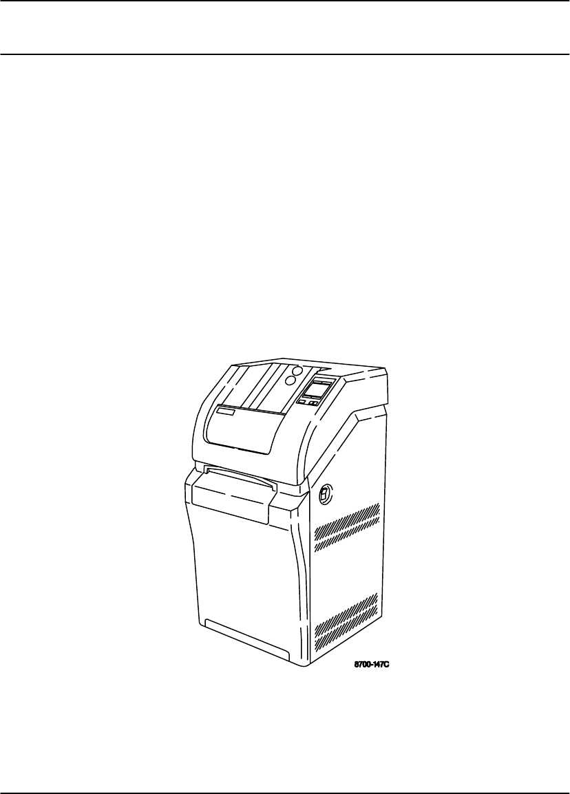
Introducing the Kodak DryView 8700 and 8500 Laser Imagers
The Kodak DryView 8700 Laser Imager (8700 Laser Imager) and the Kodak
DryView 8500 Laser Imager (8500 Laser Imager) are continuous–tone laser
imagers with an integrated photothermographic film developer.
The two imagers are nearly identical except for film size. The 8700 Laser Imager
uses only 14” x 17” (35 x 43 cm) Kodak DryView Laser Imaging Film (DryView film).
The 8500 Laser Imager also uses DryView film but accepts only 11 in. x 14 in.
(28 x 35 cm) film sheets.
Both film sizes are available in clear or blue base, packaged in 125-sheet Kodak
Instant Daylight Load Film Cartridges.
The 8700/8500 Laser Imagers are both available in three different configurations,
with two different remote keypads, described later in this manual.
Figure 1-1. Kodak DryView 8700/8500 Laser Imager

User Guide
1-2 8599110 2001 March Rev. B
System Configurations
The 8700/8500 Laser Imagers are both available in three different configurations.
Key features of each configuration are:
8700/8500 Laser Imager Standard System
Supports up to two inputs (can be upgraded to support multiple inputs).
Provides up to 64 megabytes of image memory, in 16 megabyte increments.
Uses copper cable for external connections.
Image acquisition and printing are accomplished via host control, Kodak
DryView 8700/8500 Keypad, or Kodak Keypad.
8700/8500 Laser Imager Plus System
Supports up to two inputs (can be upgraded to support multiple inputs).
Provides up to 128 megabytes of image memory, in 32 megabyte increments.
Uses fiber optic cable for external connections.
Image acquisition and printing are accomplished via host control or Kodak
Keypad.
Multi-Input/Dual Printer System
Consists of an 8700 or 8500 Dual Printer connected to a Kodak DryView 8800
Multi-Input Manager (8800 Multi–Input Manager) or 969 HQ Laser Imager.
Supports up to eight inputs.
Provides 32 or 64 megabytes of image memory per input.
Uses fiber optic cable for external connections.
Image acquisition and printing are accomplished via host control or Kodak
Keypad.
The 8800 Multi–Input Manager can provide output connects for one or two laser
printers. Connects to any of the following printers:
–Kodak DryView 8700 Laser Imager
–Kodak DryView 8500 Laser Imager
–Kodak DryView 8300 Laser Imager
–969 HQ Laser Imager
If dual printers are connected, the two printers can be the same or mixed.

Introduction
1-3
2001 March Rev. B 8599110
Keypad Feature Comparison
This table compares the features provided by the DryView 8700/8500 Keypad and
the Kodak Keypad. Note that the Kodak Keypad is available with all DryView
8700/8500 Laser Imager systems, but the DryView 8700/8500 Keypad is available
only with the DryView 8700/8500 Laser Imager Standard system.
Feature DryView 8700/8500 Keypad Kodak Keypad
Format Select Yes Yes
Custom Formats No Yes
Multiple Copies Setting Yes Yes
Sequential Image Acquire Yes Yes
Random Image Acquire No Yes
Sequential Image Erase Yes Yes
Random Image Erase No Yes
Move Acquired Image No Yes
Print Yes Yes
Stop Print Yes Yes
Density or Dmax Setting No * Yes
Contrast Setting No * Yes
Print Density Test No * Yes
Print Contrast Test No * Yes
Smooth/Sharp Select No Yes
Image Polarity Select No Yes
Image Framing Select No Yes
Auto-Print Select No ** Yes
Auto-Format Select No ** Yes
Alarm Volume Setting No Yes
* Can be set at the imager’s local panel.
** Can be set by service personnel during installation.

User Guide
1-4 8599110 2001 March Rev. B
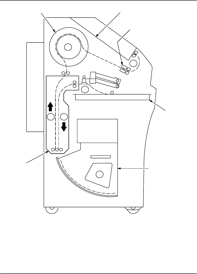
How the 8700/8500 Laser Imager Works
The following sequence occurs each time the 8700/8500 Laser Imager receives a
print command. The circled numbers in Figure 1-2 correspond to the numbered
steps below. Dashed lines indicate the film path.
1. Suction cups in the pickup area lift a single sheet of film out of the supply
cartridge and feed it into the film transport rollers.
2. The film transport drives the film down into the exposure module.
3. The film is exposed by a laser beam and then fed back into the film transport.
4. The film transport drives the film up into the film developer.
5. As the film passes over the film developer drum, the heat generated by the drum
develops the film.
6. The film transport drives the film out of the film developer, through the
densitometer, and out to the receive tray. The densitometer is a key element in
the Kodak Automatic Image Quality Control (AIQC) process, which allows the
imager to automatically adjust image processing parameters to ensure optimum
image quality.
Introduction
1-5
2001 March Rev. B 8599110
1
2
3
4
5
6
Supply
Cartridge
Receive Tray
Densitometer
Film Developer
Exposure
Module
Film
Transport
Figure 1-2. Print Sequence

User Guide
1-6 8599110 2001 March Rev. B
BLANK PAGE
Controls and Indicators
2-1
2001 March Rev. B 8599110
Controls and Indicators
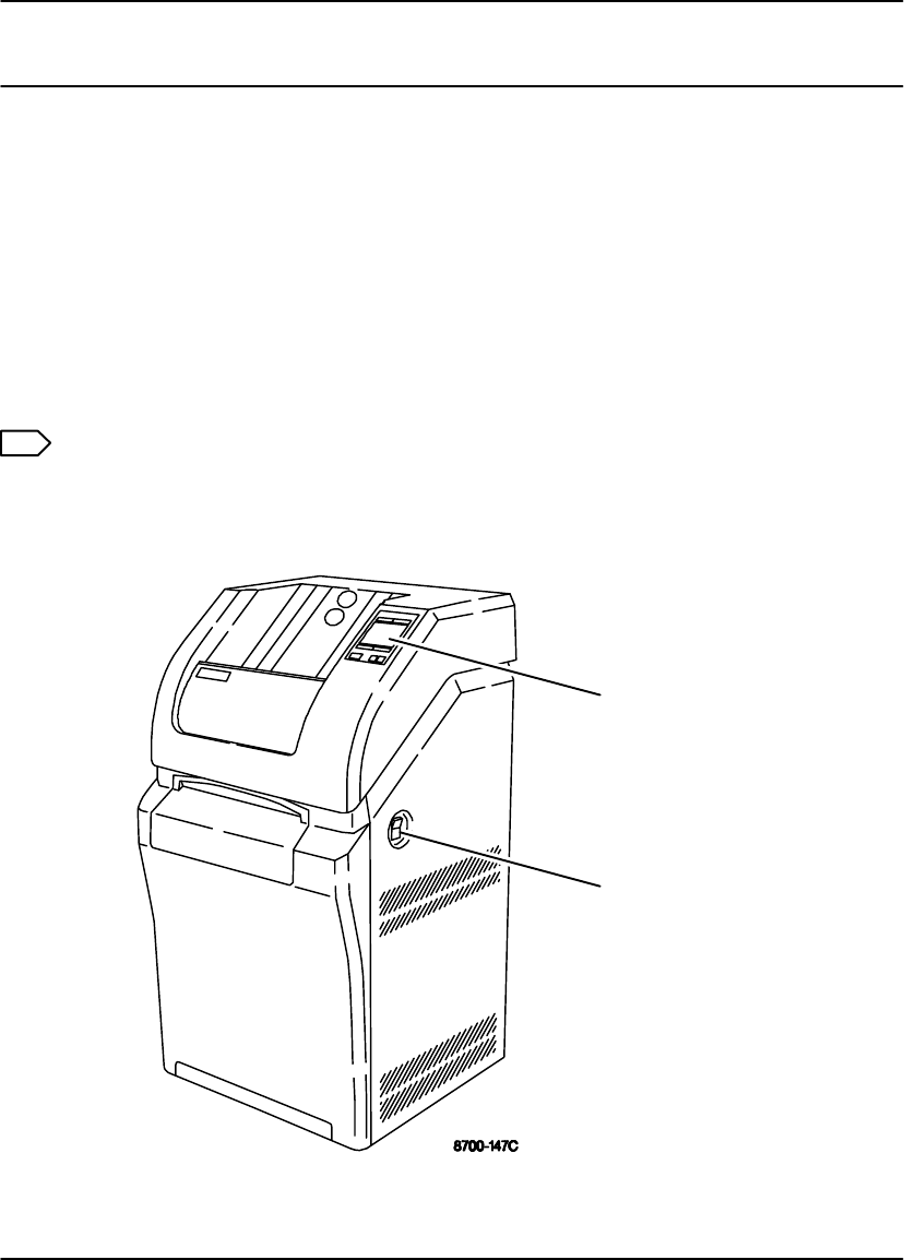
Kodak DryView 8700/8500 Laser Imager
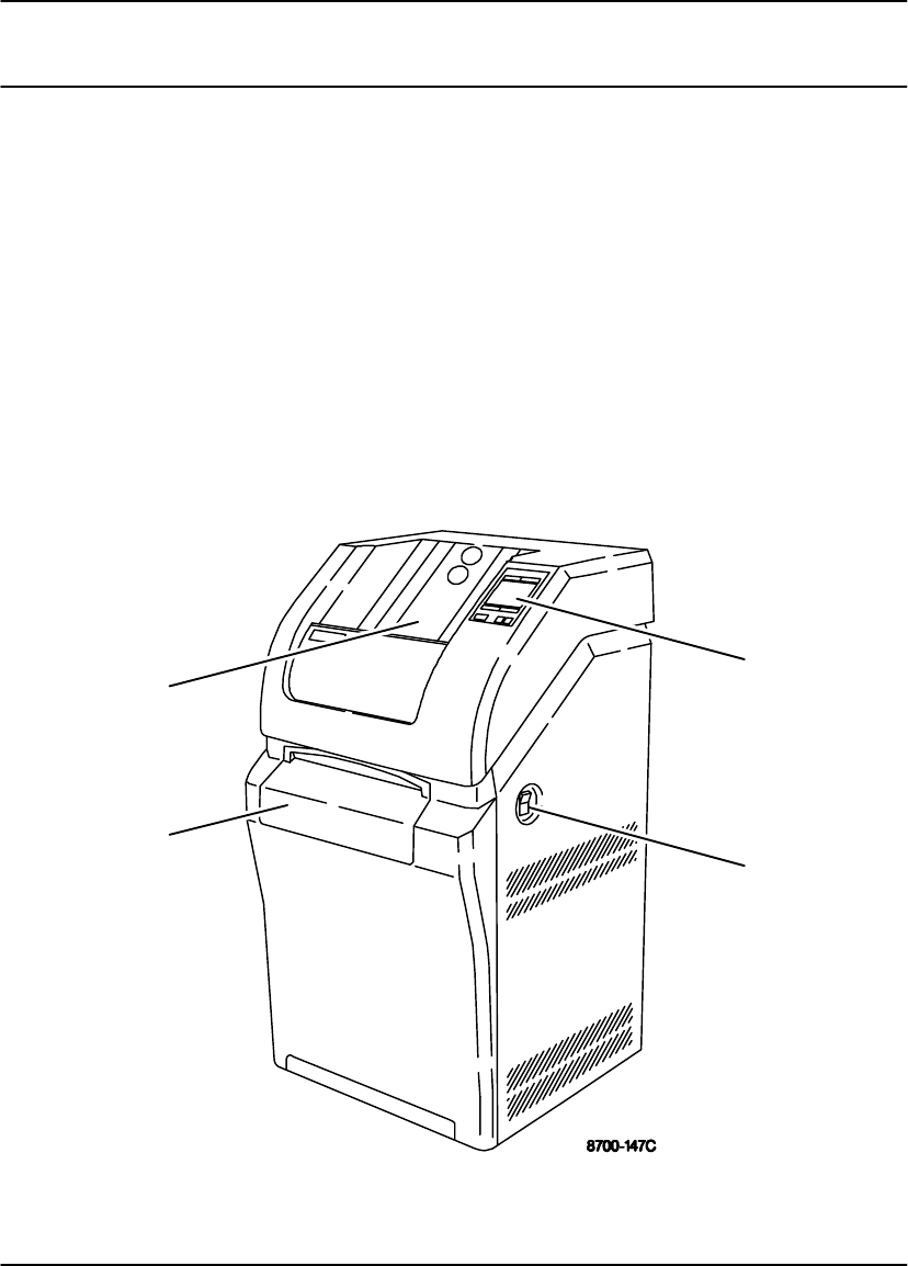
The controls and indicators for the Kodak DryView 8700/8500 Laser Imager
(8700/8500 Laser Imager) are identified in the figure. The numbered descriptions
correspond to the numbered callouts in Figure 2-1.
1. Local Panel – Includes a message display, status indicator lights, and push
button controls. For more detailed description, refer to Local Panel in this
section.
2. Power Switch – Controls power to the imager.
3. Supply Door – Enables access to the film cartridge.
4. Receive Tray – Collects developed film.
1
2
3
4
Figure 2-1. 8700/8500 Laser Imager – Controls and Indicators

User Guide
2-2 8599110 2001 March Rev. B
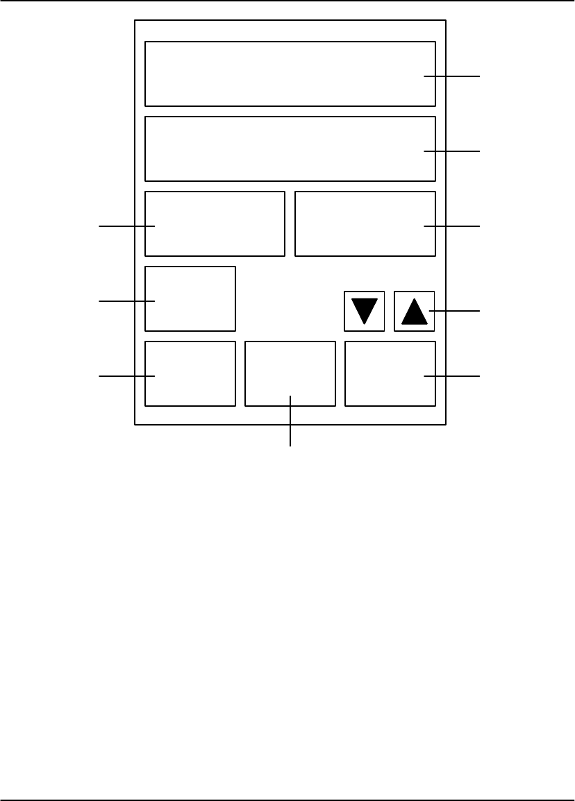
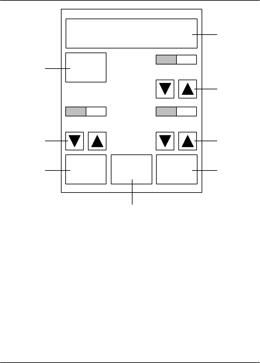
Local Panel
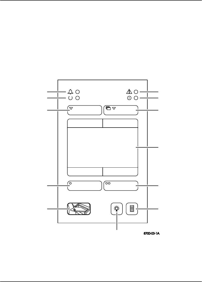
The numbered descriptions correspond to the numbered callouts in Figure 2-2.
1. Attention Light – Indicates a condition that may affect imager operation (e.g.,
imager warming or film low). Check the display for a related message.
2. Power Light – Indicates the imager is powered up.
3. Next Button –
Main Menu displayed: Used to scroll through status/error messages.
User Settings menu displayed: Used to move from one parameter to the
next.
4. Display – Displays messages, menus, and button labels.
5. User 2/+ Button –
Main Menu displayed: Used to access the User 2 Settings menu.
User Settings menu displayed: Used to increase the contrast or density
setting .
Note
The User 2/+ button has no function on Multi-Input/Dual Printer systems. Refer to
the 8800 Multi–Input Manager User Guide for instructions on setting contrast and
density and for printing test films on Multi-Input/Dual Printer systems.
6. Calibration Button – Initiates a calibration film is printing.
7. Light Control Button – Disables the indicator lights and display backlighting.
8. Supply Button – Opens the supply door.
9. User 1/–/Print Button –
Main Menu displayed: Used to access the User 1 Settings menu.
User Settings menu displayed: Used to decrease the contrast or density
setting, or to initiate printing of a contrast or density test sheet.
Note
The User 1/–/Print button has no function on Multi-Input/Dual Printer systems. Refer
to the 8800 Multi–Input Manager User Guide for instructions on setting contrast and
density and for printing test films on Multi-Input/Dual Printer systems.
Controls and Indicators
2-3
2001 March Rev. B 8599110
10. Test/Return Button –
Multi–Input/Dual Printer systems: Used to initiate a test print.
User Settings menus on Standard and Plus systems: Used to return to
the Main Menu.
11. Ready Light – Indicates the imager is ready to begin its next operation.
12. Alarm Light – Indicates an error condition exists (e.g., film jam or door open),
and imager operation can not continue until the error is cleared. Check the
display for a related message.
1
2
3
4
5
68
9
10
11
12
7
Laser Imager Ready
14 x 17 Blue
Supply: 123
Printed: 9870
User 1 User 2
Next
Figure 2-2. Local Panel Controls

User Guide
2-4 8599110 2001 March Rev. B
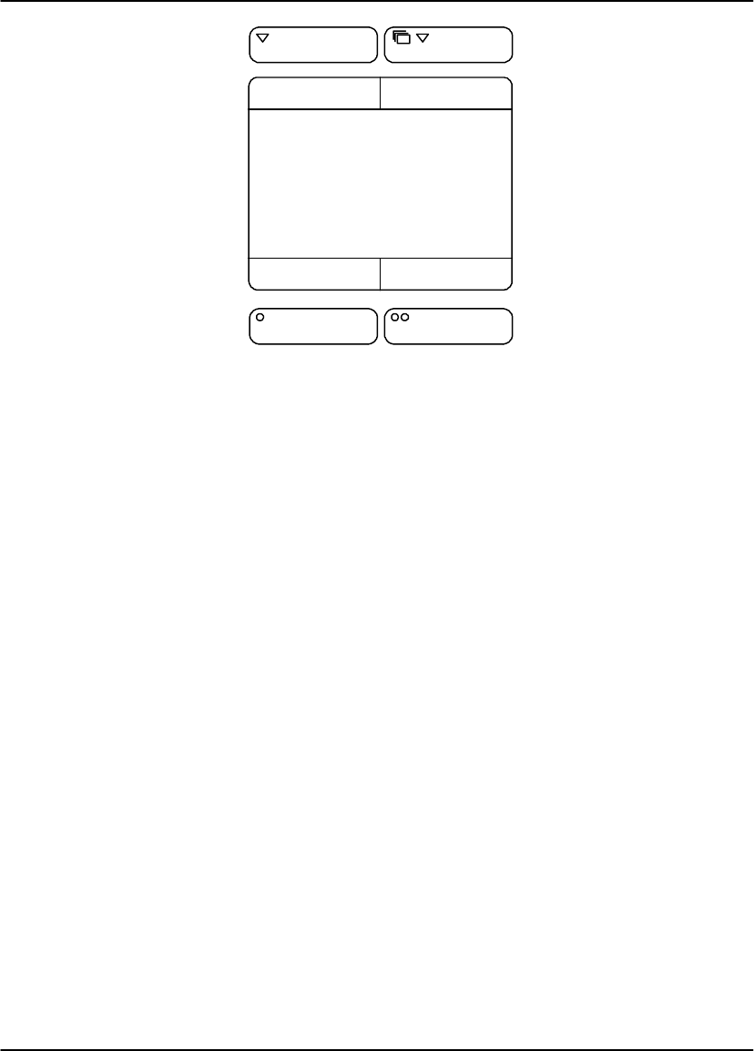
Local Panel – Main Menu
The center box displays system status and error messages. The four smaller boxes
display labels that indicate the function of the buttons immediately above and below
the display. Note that the functions of the buttons vary depending on the type of
system. Figure 2-3 shows the labels displayed for Standard and Plus systems.
Figure 2-4 shows the labels displayed for Multi-Input/Dual Printer systems.
Laser Imager Ready
14 x 17 Blue
Supply: 123
Printed: 9870
User 1 User 2
Next
Figure 2-3. Local Panel Main Menu – Standard and Plus Systems
Controls and Indicators
2-5
2001 March Rev. B 8599110
Laser Imager Ready
14 x 17 Blue
Supply: 123
Printed: 9870
NextTest
Figure 2-4. Local Panel Main Menu – Multi-Input/Dual Printer Systems
The Test button is not displayed or available on an 8500 Dual Printer.
Pressing the Test button on an 8700 Dual Printer initiates a density test film print
containing a SMPTE test pattern.

User Guide
2-6 8599110 2001 March Rev. B
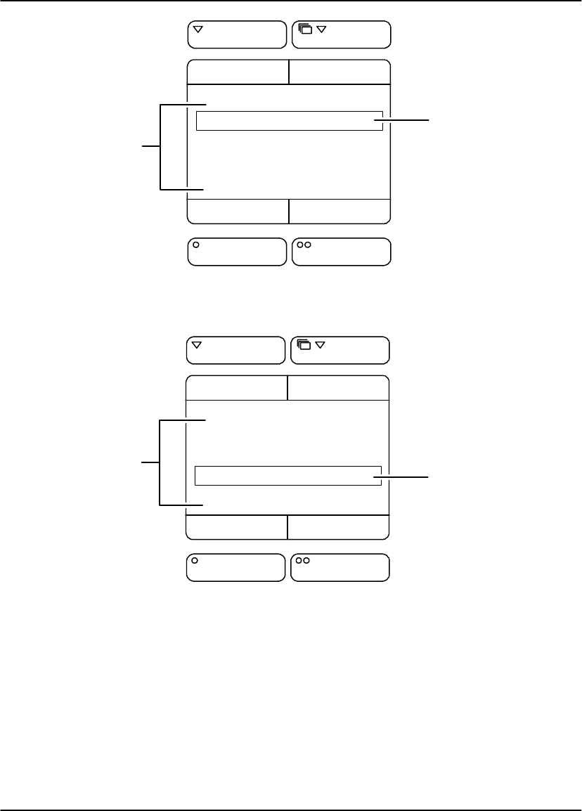
Local Panel – User Settings Menu
Note
The Local Panel User Settings Menu applies only to 8700/8500 Standard and Plus
systems. For Multi–Input 8700/8500 Dual Printer systems, refer to the 8800
Multi–Input Manager User Guide for instructions on setting contrast and density and
printing test films.
The center box on the User Settings Menu displays a menu. The currently selected
menu item is surrounded by a rectangle.
The four smaller boxes display labels that indicate the function of the buttons
immediately above and below the display. The two bottom labels depend on which
menu item is currently selected:
If Contrast or DMAX is selected, the + and – labels are displayed. Refer to
Figure 2-5.
If Contrast Test or Density Test is selected, the Print label is displayed. Refer to
Figure 2-6.
Each menu item is described below:
Contrast – When selected, pressing the + or – buttons increases or decreases
the contrast setting (range: 1 to 15 for positive contrast and –1 to –15 for
negative contrast).
DMAX – When selected, pressing the + or – buttons increases or decreases the
density setting. If AIQC (Automatic Image Quality Control) is active, the selected
Dmax setting is displayed (range: 1.70 – 3.10). If AIQC is not active, the selected
density setting is displayed (range: 1 – 16).
Contrast Test – When selected, pressing the Print button initiates a contrast test
film print. The last image stored is printed 15 times using 15 different contrast
settings. On either an 8700 or 8500 Standard or Plus system, the 15 images
may be printed on a single film sheet or the 15 different contrast images may be
printed on multiple–film sheets, depending on the acquired image size.
Density Test – When selected, pressing the Print button initiates a density test
film print containing a SMPTE test pattern.
Controls and Indicators
2-7
2001 March Rev. B 8599110
User 1
Contrast: 8
DMAX: 2.90
Contrast Test
Density Test
–+
NextReturn
Menu Items
Selected Item
Figure 2-5. User Settings Menu – Contrast Setting Selected
User 1
Contrast: 8
DMAX: 2.90
Contrast Test
Density Test
Print
NextReturn
Menu Items Selected Item
Figure 2-6. User Settings Menu – Contrast Test Selected

User Guide
2-8 8599110 2001 March Rev. B
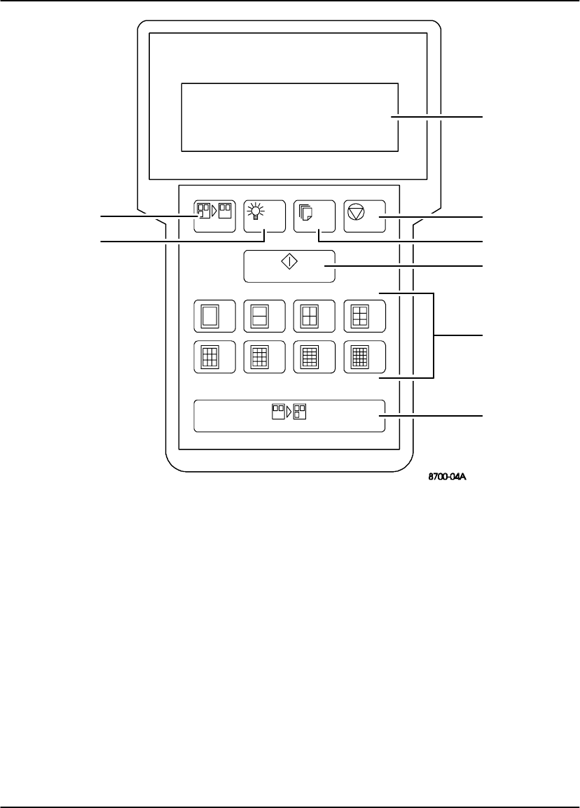
DryView 8700/8500 Keypad
Note
The DryView 8700/8500 Keypad is used only on 8700/8500 Laser Imager Standard
systems.
The numbered descriptions correspond to the numbered callouts in Figure 2-7.
1. Display – Displays system status information.
2. Stop Key – Stops the most recently queued print job. The job, including any
unprinted multiple copies, is deleted from the print queue.
3. Copies Key – Sets the copy count (range: 1 – 9).
4. Print Key – Places a print request in the print queue.
5. Format Keys – Used to select the desired image format.
6. Acquire Key – Used to acquire and store images in sequential order, starting in
the top row and working from left to right in each row.
7. Light Key – Adjusts the brightness of the display backlighting.
8. Erase Key – Deletes images in reverse order, starting with the last image stored.
Controls and Indicators
2-9
2001 March Rev. B 8599110
Acquire
Erase Light Copies Stop
Print
READY
Film:125 Queue:90
Next:1/20 Copies:9
––––––––––––––––––––
1
2
3
4
5
6
8
7
1246
9121520
Figure 2-7. DryView 8700/8500 Keypad

User Guide
2-10 8599110 2001 March Rev. B
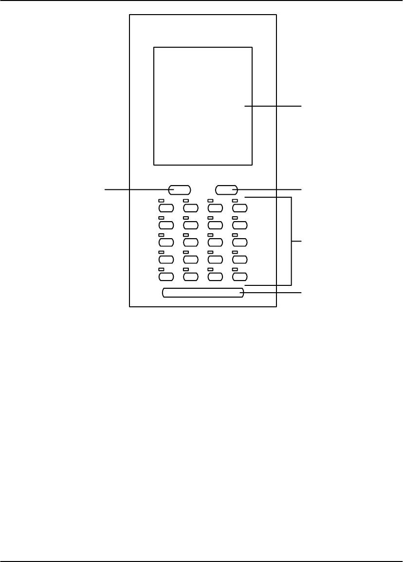
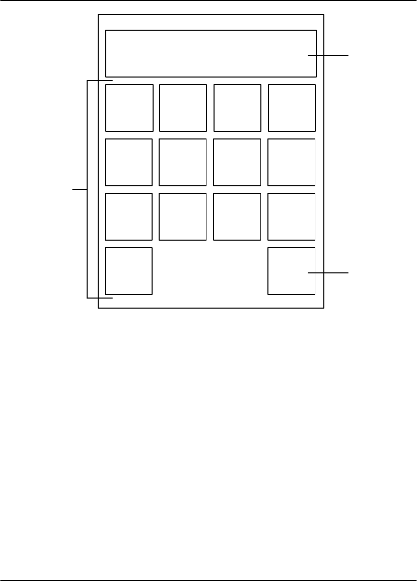
Kodak Keypad
Note
The Kodak Keypad is used on 8700/8500 Laser Imager Standard and Plus systems
and on Multi–Input/Dual Printer systems.
The numbered descriptions correspond to the numbered callouts in Figure 2-8.
1. Touch Screen – Displays a variety of menus used for system configuration and
operation. These menus are described later in this section.
2. Print Button – Places a print request in the print queue.
3. Store Buttons – Used to acquire and store images in specific positions for
printing. LEDs above each button indicate used (red) and available (green)
storage locations.
4. Sequential Store Button – Used to acquire and store images in sequential
order, starting in the top row, and working from left to right in each row.
5. Erase Button – Used to enter Erase Image mode, which allows random erasure
of any or all stored images.
Controls and Indicators
2-11
2001 March Rev. B 8599110
1
2
3
4
5
Figure 2-8. Kodak Keypad

User Guide
2-12 8599110 2001 March Rev. B
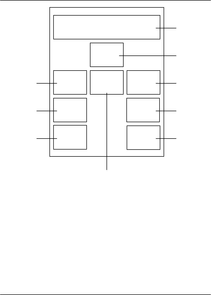
Kodak Keypad – Main Menu
The numbered descriptions correspond to the numbered callouts in Figure 2-9.
1. Attention Message Area – Displays system status and error messages.
2. Imager Information Area #1 – Indicates the status (active or OFF) of Automatic
Image Quality Control (AIQC) and the percentage of free image memory.
3. Imager Information Area #3 – Indicates the number of films remaining in the
supply cartridge, the number of prints in the print queue, and the total number of
completed prints.
4. Copy Count Set Buttons – Used to increase or decrease the copy count
(range: 1 – 99).
5. Stop Print Button – Stops the most recently queued print job. The job, including
any unprinted multiple copies, is deleted from the print queue.
6. Format Menu Button – Used to access the Format Menu.
Note
When in Erase Image mode, the Erase All Images button is displayed in place of the
Format Menu button. The Erase All Images button is used to erase all stored images
from the current format.
7. Keypad Menu Button – Used to access the Keypad Menu.
8. Imager Menu Button – Used to access the Imager Menu.
9. Imager Information Area #2 – Indicates the status of the auto print and auto
format functions (ON or OFF).
Controls and Indicators
2-13
2001 March Rev. B 8599110
Keypad
Menu Format
Menu Stop
Print
Imager
Menu
Laser Imager 1 Status:
Ready
Auto Print ON
Auto Format ON Media: 14 X 17
Supply: 125
Queued: 10
Printed: 1231
Imager 1
Automatic Image Quality Control Active
Memory Free 100%
Main Menu
ERASE PRINT
Copies: 2
1
2
3
4
5
6
7
8
9
Figure 2-9. Kodak Keypad – Main Menu

User Guide
2-14 8599110 2001 March Rev. B
Kodak Keypad – Format Menu
The numbered descriptions correspond to the numbered callouts in Figure 2-10.
1. Attention Message Area – Displays system status and error messages.
2. RETURN Button – Used to return to the Main Menu without selecting a format.
3. Format Select Buttons – Used to select the desired image format. Buttons are
only displayed for those formats that are currently available. The available
formats include:
Nine fixed formats (1:1, 2:1, 4:1, 6:1, 9:1, 12:1, 15:1, 16:1, and 20:1).
Up to four custom formats. Custom formats (also referred to as mixed
formats) are set up by service personnel based on operator input.
–For custom formats on 8700 and 8500 Laser Imager Standard and Plus
systems, images within each row must all be the same size. Image size
can vary from row to row.
–For custom formats on Multi–Input/Dual Printer systems, the images can
be different sizes and randomly arranged on the film.
Controls and Indicators
2-15
2001 March Rev. B 8599110
Laser Imager 1 Status:
Ready
Format Menu
CUSTOM
FORMAT
A
CUSTOM
FORMAT
B
CUSTOM
FORMAT
C
CUSTOM
FORMAT
D
1246
9 121516
20 RETURN
1
2
3
Figure 2-10. Kodak Keypad – Format Menu

User Guide
2-16 8599110 2001 March Rev. B
Kodak Keypad – Imager Menu
The numbered descriptions correspond to the numbered callouts in Figure 2-11.
1. Attention Message Area – Displays system status and error messages.
2. Contrast, Density, & Count Menu Button – Used to access the Contrast,
Density, & Count Menu.
3. Print Density Test Button – Initiates a density test film print containing a
SMPTE test pattern.
4. Image Polarity Button – Selects positive or negative image polarity.
5. RETURN Button – Used to return to the Main Menu.
6. Image Framing Button – Sets image framing to ON or OFF. When set to ON, a
one pixel frame is printed around each image.
7. Output Button – Selects the desired output destination (Imager 1 or Imager 2).
This button is not displayed if the keypad is connected to a Standard or Plus
system.
8. Image Processing Button – Selects smooth or sharp image processing. (The
choice depends on the personal preference of the viewer.)
9. Print Contrast Test Button – Initiates a contrast test film print. The last image
stored is printed 15 times using 15 different contrast settings. On either an 8700
or 8500 Laser Imager Standard or Plus system, the 15 images may be printed on
a single film sheet or the 15 different contrast images may be printed on multiple
film sheets depending on the acquired image size.
Controls and Indicators
2-17
2001 March Rev. B 8599110
RETURN
Image
Processing
SMOOTH
Laser Imager 1 Status:
Ready
Imager Menu
ERASE PRINT
1
2
57
8
Print
Contrast
Test
Image
Framing
ON
Print
Density
Test 39
Contrast,
Density,
& Count
Menu
Output
Imager 1
4
Image
Polarity
POSITIVE
6
Figure 2-11. Kodak Keypad – Imager Menu

User Guide
2-18 8599110 2001 March Rev. B
Kodak Keypad – Contrast, Density, & Count Menu
The numbered descriptions correspond to the numbered callouts in Figure 2-12.
1. Attention Message Area – Displays system status and error messages.
2. Reset Printed Count Button – Resets the printed count value to zero (displayed
in Imager Information Area #3 on the Main Menu).
3. Density Set Buttons – Used to increase or decrease the density setting. If
Automatic Image Quality Control (AIQC) is active, the selected Dmax setting is
displayed (range: 1.70 – 3.10). If AIQC is not active, the selected density setting
is displayed (range: 1 – 16).
4. RETURN Button – Used to return to the Imager Menu.
5. Contrast Set Buttons – Used to increase or decrease the contrast setting
(range: 1 through 15).
Controls and Indicators
2-19
2001 March Rev. B 8599110
Reset
Printed
Count
RETURN
K190:
Changing the contrast and/or
density will affect image quality.
Contrast, Density, & Count Menu
ERASE PRINT
1
3
4
5
DMAX 2.10Contrast 12
2
Figure 2-12. Kodak Keypad – Contrast, Density, & Count Menu

User Guide
2-20 8599110 2001 March Rev. B
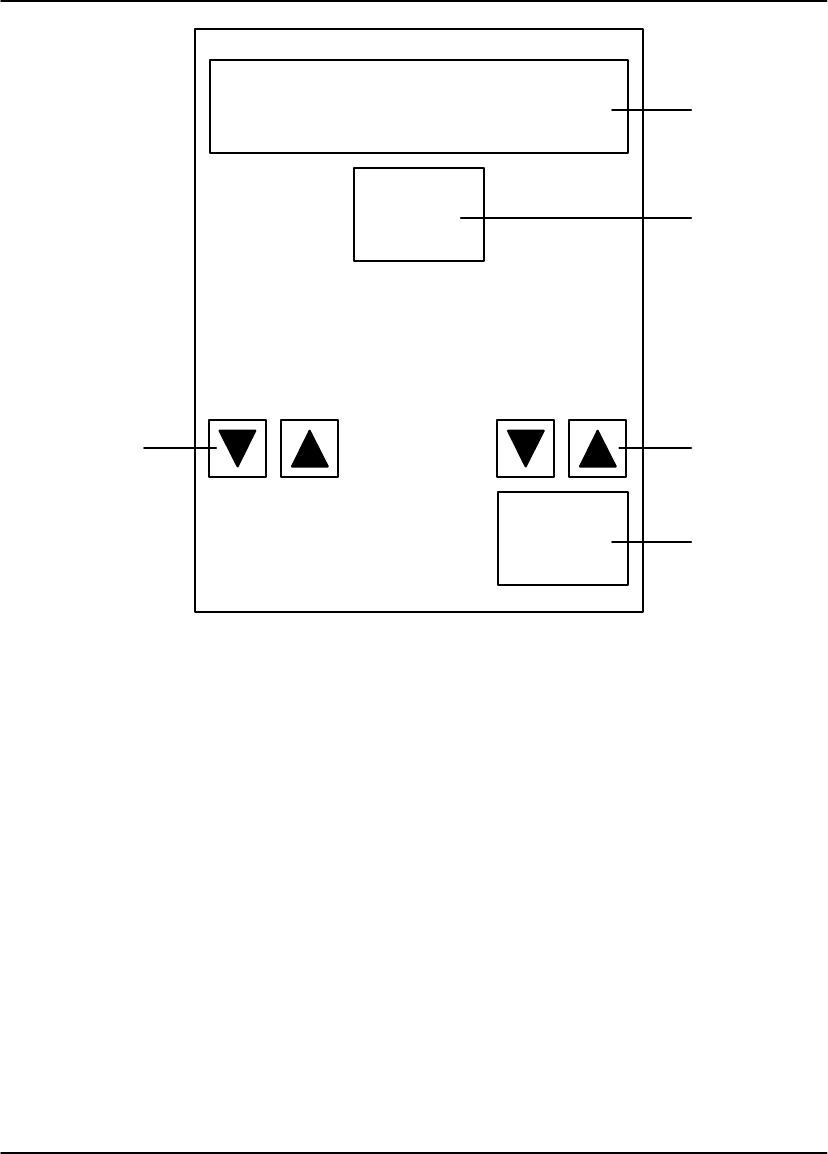
Kodak Keypad – Keypad Menu
The numbered descriptions below correspond to the numbered callouts in
Figure 2-13.
1. Attention Message Area – Displays system status and error messages.
2. Display Brightness Set Buttons – Sets the keypad display brightness.
3. Alarm Beep Volume Set Buttons – Sets the keypad alarm beep volume.
4. RETURN Button – Used to return to the Main Menu.
5. Auto Print Button – Sets the auto print function to ON or OFF. When set to ON,
a print is automatically queued after the last image is stored (the Print button
does not have to be pressed).
6. Auto Format Button – Sets the auto format function to ON or OFF. When set to
ON, a new format is automatically displayed after a print is queued (i.e., the
LEDs above the store buttons change from red to green).
7. Key Beep Volume Set Buttons – Sets the key beep volume.
8. Color Blind Mode Button – Sets the color blind feature to ON or OFF. When set
to ON, the red LEDs above the Store buttons (which indicate used storage
locations) blink instead of staying on constantly. This allows the red LEDs to be
differentiated from the constant green LEDs (which indicate available storage
locations).
Note
When in Erase Image mode, the red LEDs blink regardless of whether the color
blind feature is ON or OFF.
Controls and Indicators
2-21
2001 March Rev. B 8599110
Auto
Print
ON
RETURN
Laser Imager 1 Status:
Ready
Keypad Menu
ERASE PRINT
5
1
3
4
7
Auto
Format
ON
Key Beep
Volume Alarm Beep
Volume
Color
Blind
Mode
OFF
Display
Brightness
2
6
8
Figure 2-13. Kodak Keypad – Keypad Menu

User Guide
2-22 8599110 2001 March Rev. B
BLANK PAGE
Operation and Maintenance
3-1
2001 March Rev. B 8599110
Operation and Maintenance
System Power Up
1. Set the imager power switch to ON.
The Power light on the local panel comes on.
The imager performs a series of self-diagnostic tests and begins a warmup
cycle. The time required for warmup varies based on how long the imager
has been turned off.
After the diagnostic tests and warmup cycle are complete, the local panel
displays “Laser Imager Ready”.
Note
Images can be acquired during the warmup cycle, but no printing will occur until the
ready message is displayed.
Local Panel
Power Switch
Figure 3-1. Power Switch and Local Panel

User Guide
3-2 8599110 2001 March Rev. B
Format/Acquire/Print – DryView 8700/8500 Keypad
1. Set the imager power switch to ON.
2. On the keypad, press Copies to select the number of copies desired.
3. Press the appropriate Format key to select the desired format.
4. Press Acquire to acquire images.
5. After the images are acquired, press Print to place a print request in the print
queue.
Note
If the auto–print function is enabled, a print request is automatically placed in the
print queue after the last image in the format has been acquired (the Print button
does not have to be pressed).
Note
For the DryView 8700/8500 Keypad, the auto–print function is enabled or disabled
by service personnel during installation. The user cannot change this setting.

Operation and Maintenance
3-3
2001 March Rev. B 8599110
Format/Acquire/Print – Kodak Keypad
1. Set the imager power switch to ON.
2. On the keypad’s Main Menu, press Copy Count Set to select the number of
copies desired.
3. Press Format Menu to access the Format Menu.
4. Press the appropriate Format Select button to select the desired format.
5. Press the appropriate Store buttons to acquire images.
6. After the images are acquired, press Print to place a print request in the print
queue.
Note
If the auto–print function is ON, a print request is automatically placed in the print
queue after the last image in the format has been stored.
7. Select a new format and/or acquire and store more images, as desired.
If the auto–format function is ON, a new format is automatically displayed,
allowing you to acquire more images.
If the auto–format function is OFF, new images cannot be acquired until a
new format is selected or the currently stored images are erased using the
Erase Image function.

User Guide
3-4 8599110 2001 March Rev. B
Density/Contrast Selection – Local Panel
Note
This procedure applies only to 8700/8500 Laser Imager Standard and Plus Systems.
For Multi–Input 8700/8500 Dual Printer systems, refer to the 8800 Multi–Input
Manager User Guide for instructions on setting contrast and density and for printing
test films.
1. Display an image on the user’s console.
2. From the console, adjust the window and level controls to achieve the desired
image quality on the display monitor.
3. Acquire the displayed image.
4. Press User 1 or User 2 on the Local Panel to display the appropriate User
Settings Menu.
5. Press Next, as required, to select Contrast Test Print.
6. Press Print to initiate a contrast test film print. The last image stored is printed 15
times, using 15 different contrast settings. On either an 8700 or 8500 Standard
or Plus system, the 15 different contrast images may be printed on a single film
sheet or on multiple film sheets, depending on the acquired image size.
7. Examine the test sheet(s) to determine if the maximum density is acceptable.
If the maximum density is acceptable, skip to Step 11.
If the maximum density is not acceptable, continue to Step 8.
8. Press Next, as required, to select DMAX.
9. Press Increase/Decrease, as required, to change the density setting.
10. Repeat steps 5 through 9 until the desired maximum density is achieved.
11. Examine the 15 images on the contrast test sheet and select the image with the
most appropriate contrast. Note the value printed next to this image.
12. Press Next, as required, to select Contrast.
13. Press Increase/Decrease, as required, to change the contrast setting to the
value of the selected image (step 11). You can select either positive or negative
contrast. Use settings 1 through 15 for positive contrast images. Use settings –1
through –15 for negative contrast images.
14. Press Return to return to the Main Menu.

Operation and Maintenance
3-5
2001 March Rev. B 8599110
Density/Contrast Selection – Kodak Keypad
Note
This procedure applies only to 8700/8500 Laser Imager Standard and Plus systems
and Multi–Input/Dual Printer systems.
1. Display an image on the user’s console.
2. From the console, adjust the window and level controls to achieve the desired
image quality on the display monitor.
3. From the Main Menu, press Format Menu, then press any Format Select button
on the Format Menu.
4. Press any lighted Store button or Sequential Store to acquire the image.
5. From the Main Menu, press Imager Menu.
6. Press Print Contrast Test. The imager prints the acquired image in a 15:1
format on a single sheet, using each of the 15 different contrast settings.
7. Examine the test sheet to determine if the maximum density is acceptable.
If the maximum density is acceptable, skip to Step 11.
If the maximum density is not acceptable, continue to Step 8.
8. From the Imager Menu, press Contrast, Density, & Count Menu, then press OK
on the Confirmation Menu.
9. Press Density Set, as required, to change the density setting. When the desired
density value is displayed, press RETURN.
10. Repeat steps 6 through 9 until the desired maximum density is achieved.
11. Examine the 15 images on the contrast test sheet and select the image with the
most appropriate contrast. Note the value printed next to this image.
12. From the Imager Menu, press Contrast, Density, & Count Menu, then press OK
on the Confirmation Menu.
13. Press Contrast Set, as required, to change the contrast setting of the selected
image. When the desired contrast value is displayed, press RETURN.
14. From the Imager Menu, press Image Polarity to select either positive or
negative image contrast.
15. From the Imager Menu, press RETURN to return to the Main Menu.

User Guide
3-6 8599110 2001 March Rev. B
Moving Stored Images – Kodak Keypad
The move function let you move a previously stored image to any available
non-stored position (i.e., any Store button with a green LED). To enable the move
function, press the Store button of the image you want moved. To complete the
move, press the Store button for the desired image position.
The move function is exited as soon as the image is stored at its new location.
To exit the move function without moving the image, press the image’s Store
button again (or press the Store button of any other stored image).
Erasing Stored Images – DryView 8700/8500 Keypad
Press Erase to erase images in reverse order, starting with the most recently
acquired image.
Erasing Stored Images – Kodak Keypad
Press Erase Image to enter Erase Image mode. While in Erase Image mode, any or
all stored images can be erased.
To erase a specific image, press Store for that image. Once all the desired
images are erased, press Erase Image to exit the Erase Image mode.
To erase all stored images, press Erase All Images on the Main Menu. After
erasing of the stored images, the keypad automatically exits Erase Image mode.
Note
When in Erase Image mode, the Erase All Images button is displayed in place of the
Format Menu button.

Operation and Maintenance
3-7
2001 March Rev. B 8599110
Deleting a Job from the Print Queue – DryView 8700/8500 Keypad
To stop the most recently queued print job, press Stop. The job, including any
unprinted multiple copies, is deleted from the print queue.
Note
You cannot delete multiple jobs from the print queue by pressing the Stop key
multiple times.
Deleting a Job from the Print Queue – Kodak Keypad
To stop the most recently queued print job, press Stop Print on the Main Menu. The
job, including any unprinted multiple copies, is deleted from the print queue.
Note
You cannot delete multiple jobs from the print queue by pressing the Stop Print
button multiple times.
User Guide
3-8 8599110 2001 March Rev. B
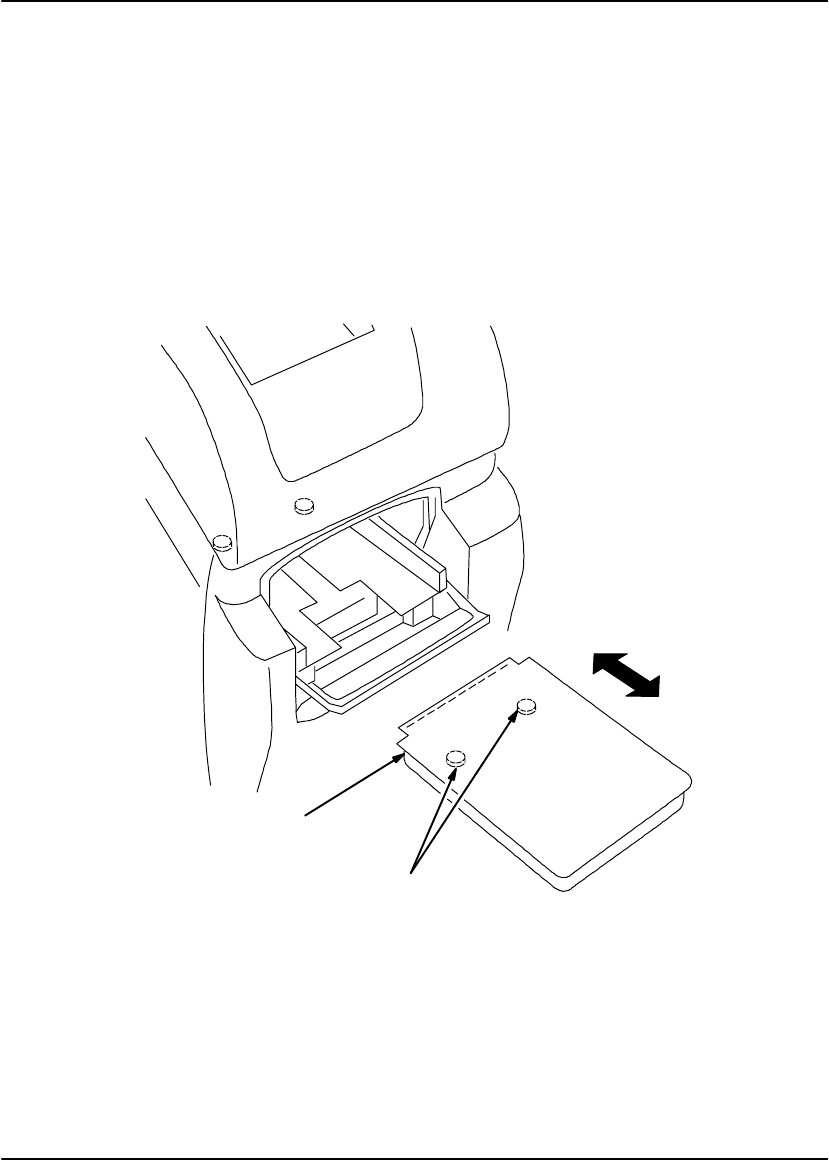
Loading/Unloading Film
1. If the supply door is not already open, press Supply on the local panel.
2. To remove the film cartridge, lift the edge of the cartridge slightly, then slide the
cartridge out of the imager.
3. To install the film cartridge, set the leading edge of the cartridge on the cartridge
guides, then slide the cartridge into the imager to engage the detents in the
bottom of the cartridge.
4. Close the supply door.
8700-43A
Leading Edge
Detents
Figure 3-2. Loading/Unloading Film
Operation and Maintenance
3-9
2001 March Rev. B 8599110
Cleaning the Platen
The platen is the inside bottom surface of the exposure module. Over time, this
surface can collect dust. This dust can create artifacts on printed images.
Supplies Required
3M Auto-Pak Tack Cloth (60-9800-0888-6)
Procedure
1. From the local panel, press Supply to close the film cartridge and open the
supply door.
2. Remove the film cartridge.
! Warning
When the power cord is plugged in, hazardous voltages are present in some areas
of the imager. These voltages can cause severe injury or death.
3. Turn off the imager and unplug its power cord.
4. Open the left door via its mechanical release (see page 4-14).
5. Open the platen access door (turn the handle counterclockwise and push in the
door).
! Caution
The anti-reflective surface of the platen is easily damaged by fingernails and jewelry.
Before cleaning the platen, remove any jewelry (rings, bracelets, watches, etc.)
which may accidentally come in contact with the platen.
If the Auto-Pak cloth catches on parts inside the exposure module, take care not to
damage the parts when removing the cloth. Check for and remove any torn pieces of
cloth.
6. Use an Auto-Pak cloth to wipe the surface of the platen, as well as the inside
surfaces close to the bottom of the exposure module.
Note
The Auto-Pak cloth will not remove large particles. Use a flashlight and fingers to
remove large particles.
User Guide
3-10 8599110 2001 March Rev. B
7. Close the platen access door after cleaning. Turn the handle fully clockwise to
latch the door.
8. Install the film cartridge.
9. Close the left door and supply door.
10. Plug in the power cord and power up the imager.
Platen Access Door
Handle
Figure 3-3.
Operation and Maintenance
3-11
2001 March Rev. B 8599110
Replacing the Developer Filter
Kodak DryView Laser Imaging Film emits a slight odor when it is developed. The
developer filter absorbs and neutralizes this odor. As the filter ages, it becomes
slightly less effective. If odor becomes noticeable, replace the filter as follows:
1. Unlatch and open the filter housing.
2. Remove the old filter.
3. Install the new filter. See the instructions on the filter package.
4. Close and latch the filter housing.
Filter
Figure 3-4. Replacing the Developer Filter

User Guide
3-12 8599110 2001 March Rev. B
BLANK PAGE

Troubleshooting
4-1
2001 March Rev. B 8599110
Troubleshooting
Local Panel and Keypad Message Types
The local panel and keypads display three types of messages.
Status
Status messages are strictly informational and require no operator action.
Note
The DryView 8700/8500 Laser Imager displays a local panel status message (P550)
when preventive maintenance and cleaning are recommended. Preventive
maintenance and cleaning ensure optimum imager performance. The P550
message will not interfere with normal operation. The intent is to let the operator
schedule a convenient time for preventive maintenance and cleaning by a certified
technician.
Action
Action messages indicate that operator action is required before imager operation
can continue. If an action message does not clear after performing the indicated
action, call for service.
Error
Error messages indicate an error condition within the imager. In some cases, error
messages can be cleared by operator action, but in most cases a service call will be
required.
Error message tables list error messages (for the DryView 8700/8500 Keypad) or
error message numbers (for the local panel and Kodak Keypad), along with the
operator action that may clear the error.

User Guide
4-2 8599110 2001 March Rev. B
Local Panel Error Message Table
This table lists all local panel error message numbers. When an error message is
displayed on the local panel, perform the operator action listed next to the message
number. If the listed action does not clear the error message, call for service.
This table does not include status or action messages. Status messages require no
operator action. Action messages include the required operator action.
Message
Number Operator Action
P116 Open and close the supply door. Press Supply on the local panel.
P121
P122
P123
P126
Turn the imager OFF, wait five seconds, then turn the imager back
ON.
P138 If pressing Supply does not unlock the door, use the mechanical
release (refer to page 4-14). Darken the room before opening the
door to expose as few sheets of media as possible.
P151
P154 Turn the imager OFF, wait five seconds, then turn the imager back
ON.
P173 Close the platen access door.
P177 Close the cartridge manually (refer to page 4-13).
P178 Close the top cover.
P203
P204
P205
P206
Turn the imager OFF, wait five seconds, then turn the imager back
ON.
P208 Use the mechanical release to open the left door (refer to page
4-14).
P221
P222
P223
P224
P225
P226
P227
Turn the imager OFF, wait five seconds, then turn the imager back
ON.

Troubleshooting
4-3
2001 March Rev. B 8599110
Message
Number Operator Action
P228 Open the left door. Grasp the transport handle and slide the
transport out of the imager, then slide it back in until it latches.
P229 Use the mechanical release to open the supply door (refer to page
4-14).
P301
P302
P303
Turn the imager OFF, wait five seconds, then turn the imager back
ON.
P501
P506 Open and close the top cover of the imager to reset the developer.
P507
P509
P551
P552
P553
P554
Turn the imager OFF, wait five seconds, then turn the imager back
ON.
P561 If this error is caused by a film jam, clearing the jam should clear
the error. If not, turn the imager OFF, wait five seconds, then turn
the imager back ON.
P601
P602
P603
P604
P605
P620
P622
P623
Turn the imager OFF, wait five seconds, then turn the imager back
ON.
P624
P625
P631
P632
P633
P634
Insert a different film cartridge and press Calibration on the local
panel.
P910
P913 Turn the imager OFF, wait five seconds, then turn the imager back
ON.

User Guide
4-4 8599110 2001 March Rev. B
Kodak Keypad Error Message Table
This table lists all Kodak Keypad error message numbers. When an error message
is displayed on the Kodak Keypad, perform the operator action listed next to the
message number. If the listed action does not clear the error message, call for
service.
This table does not include status or action messages. Status messages require no
operator action. Action messages include the required operator action.
Message
Number Operator Action
K1
K3
K4
K9
Turn the imager OFF, wait five seconds, then turn the imager back
ON.
K58 Select a format with fewer images.
K73 Refer to local panel message.
K85 Wait for some images to be printed.
K183 Check for objects laying on the keypad or footswitch.
K184 Call for service.
K202 Refer to local panel message.
K203 Call for service.
K209
K215 Refer to local panel message.
K230 Insert a different film cartridge and press the calibration button on
the local panel.

Troubleshooting
4-5
2001 March Rev. B 8599110
DryView 8700/8500 Keypad Error Message Table
This table lists all DryView 8700/8500 Keypad error messages. When an error
message is displayed on the DryView 8700/8500 Keypad, perform the operator
action listed next to the message. If the listed action does not clear the error
message, call for service.
This table does not include status or action messages. Status messages require no
operator action. Action messages include the required operator action.
Message Operator Action
Acquire Failure – 59
Acquire Failure – 65
Acquire Failure – 68
Acquire Failure – 72
Try acquiring again.
Cover Open Refer to local panel message.
Error – Check Imager Refer to local panel message.
Media Jam Refer to local panel message.
Memory Full Wait for some images to be printed, then
continue acquiring.
No Cassette Refer to local panel message.
Supply Out Refer to local panel message.
User Guide
4-6 8599110 2001 March Rev. B
Removing Jams from Area 1
Note
When jams occur in Area 1, the film cartridge does not close. If the left door is
opened, the top sheets of film in the cartridge will be exposed. To minimize the
number of exposed sheets, darken the room before opening the left door.
1. From the local panel, press and hold Supply for five seconds to unlock the left
door and supply door.
2. Swing open the left door.
3. Reach into the pickup area and remove the jammed film.
4. Close the left door and supply door.
Pickup Area
Figure 4-1. Removing Jams from Area 1

Troubleshooting
4-7
2001 March Rev. B 8599110
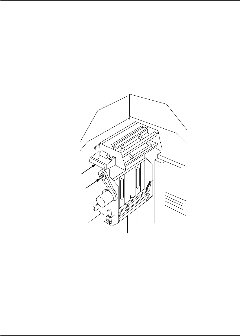
Removing Jams from Area 2a
1. Open the left door (the imager automatically unlocks the door).
2. Squeeze the transport handle and slide the assembly out of the imager.
3. Push in the lever at the bottom of the transport. The film should drop out of the
transport; if not, reach through the access holes and push the film down and out
of the transport.
4. After removing the jam, slide the transport assembly in until it latches (do not
squeeze the transport handle), then close the left door.
Lever
Access Holes
Handle
Figure 4-2. Removing Jams from Area 2a
User Guide
4-8 8599110 2001 March Rev. B
Removing Jams from Area 2b
1. Open the left door (the imager automatically unlocks the door).
2. Squeeze the transport assembly handle and slide the assembly out of the
imager.
3. Turn the knob on the side of the transport clockwise to drive the film out the top
of the transport.
4. After removing the jam, slide the transport assembly in until it latches (do not
squeeze the transport handle), then close the left door.
Handle
Knob
Figure 4-3. Removing Jams from Area 2b
Troubleshooting
4-9
2001 March Rev. B 8599110
Removing Jams from Area 3
1. Open the left door (the imager automatically unlocks the door).
2. Open the platen access door (turn the handle counterclockwise and push the
door in).
3. Reach into the platen and remove the jammed film.
Note
If there is no film in the platen, check for the film in Area 2a (refer to page 4-7).
4. Close the platen access door. Turn the handle fully clockwise to latch the door.
5. Close the left door.
Platen Access Door
Handle
Figure 4-4. Removing Jams from Area 3

User Guide
4-10 8599110 2001 March Rev. B
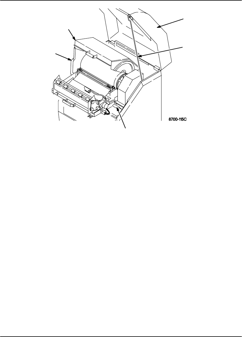
Removing Jams from Area 4
1. Raise the top cover to its highest position, then lower it slightly to engage the
support rod.
2. Grasp the developer/exit assembly handle and lift up to unlatch it, then slide the
assembly out of the imager.
3. Grasp the developer cover handle. Raise the cover to its highest position, then
lower it slightly to engage the support arm.
! Caution
The drum and rollers inside the developer are hot. Use caution when removing
jammed film from the developer.
To prevent damage to the surface of the developer drum, do not use any type of
tool to remove jammed film.
4. Remove the jammed film.
5. Lift the developer cover slightly, pull the support arm forward, then carefully close
the cover.
6. Push down the release lever on the right side of the developer/exit assembly,
then slide the assembly into the imager until the handle latches.
7. Raise the the top cover slightly, push the support rod backward, then carefully
close the cover.
Troubleshooting
4-11
2001 March Rev. B 8599110
Developer Cover
Release Lever
Support Arm Support Rod
Top Cover
Figure 4-5. Removing Jams from Area 4
User Guide
4-12 8599110 2001 March Rev. B
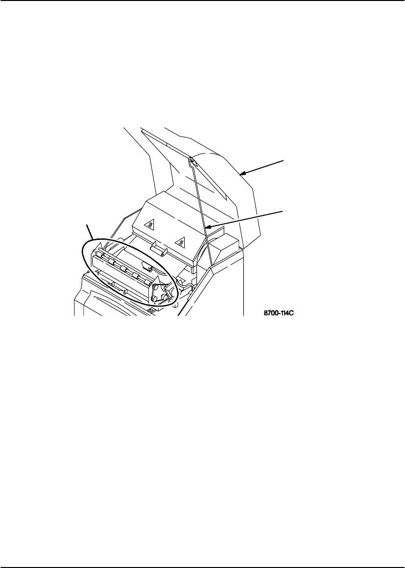
Removing Jams from Area 5
1. Raise the top cover to its highest position, then lower it slightly to engage the
support rod.
2. Remove the jammed film.
3. Raise the the top cover slightly, push the support rod backward, then carefully
close the cover.
Area 5 Support Rod
Top Cover
Figure 4-6. Removing Jams from Area 5
Troubleshooting
4-13
2001 March Rev. B 8599110
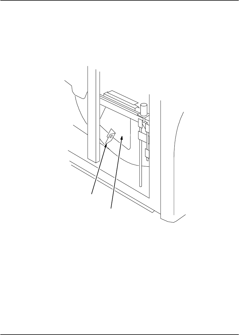
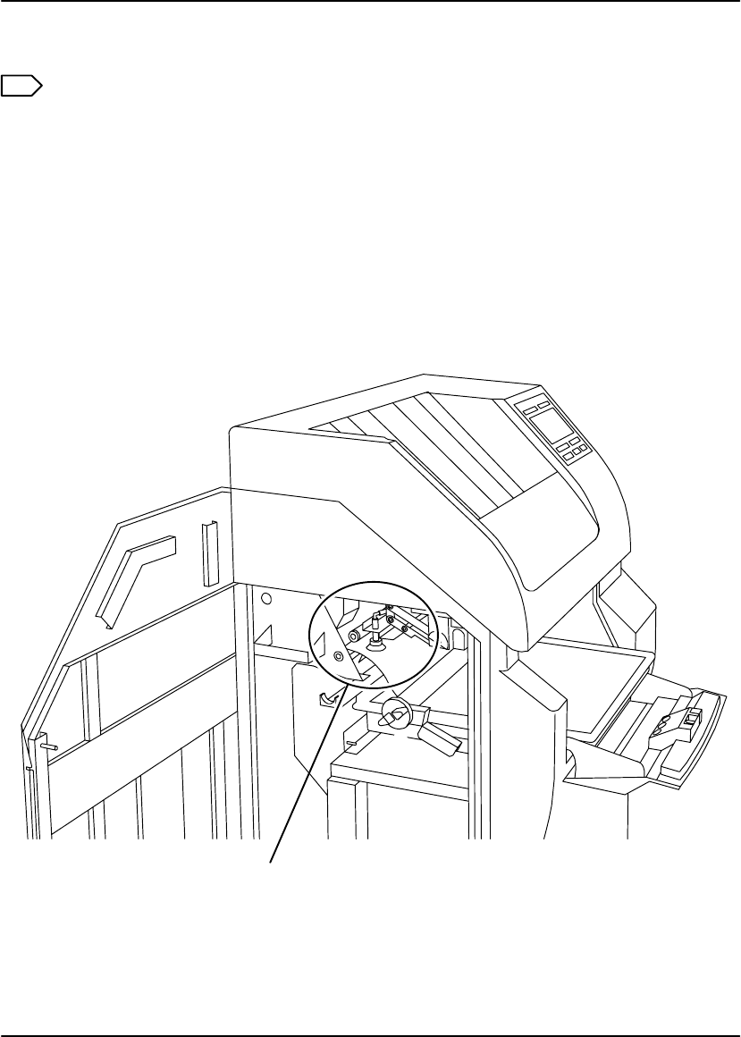
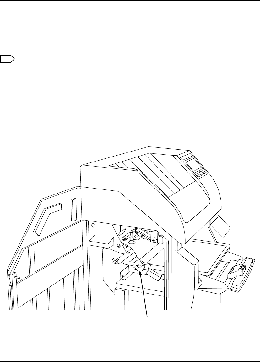
Manually Closing the Film Cartridge
The imager automatically closes the film cartridge when Supply is pressed, when
the cartridge is empty, and when film jams occur in the expose or transport areas. If
the imager cannot close the cartridge, a P177 error message is displayed.
Note
If doors are opened when the film cartridge is open, the top sheets of film will be
exposed. To minimize the number of exposed sheets, darken the room before
opening the doors.
Press and hold Supply for five seconds to unlock the left door and supply door. If
the imager cannot unlock the door(s), use their mechanical releases (refer to
page 4-14).
To close the cartridge, turn the rollback knob counterclockwise.
Rollback Knob
Figure 4-7. Manually Closing the Film Cartridge

User Guide
4-14 8599110 2001 March Rev. B
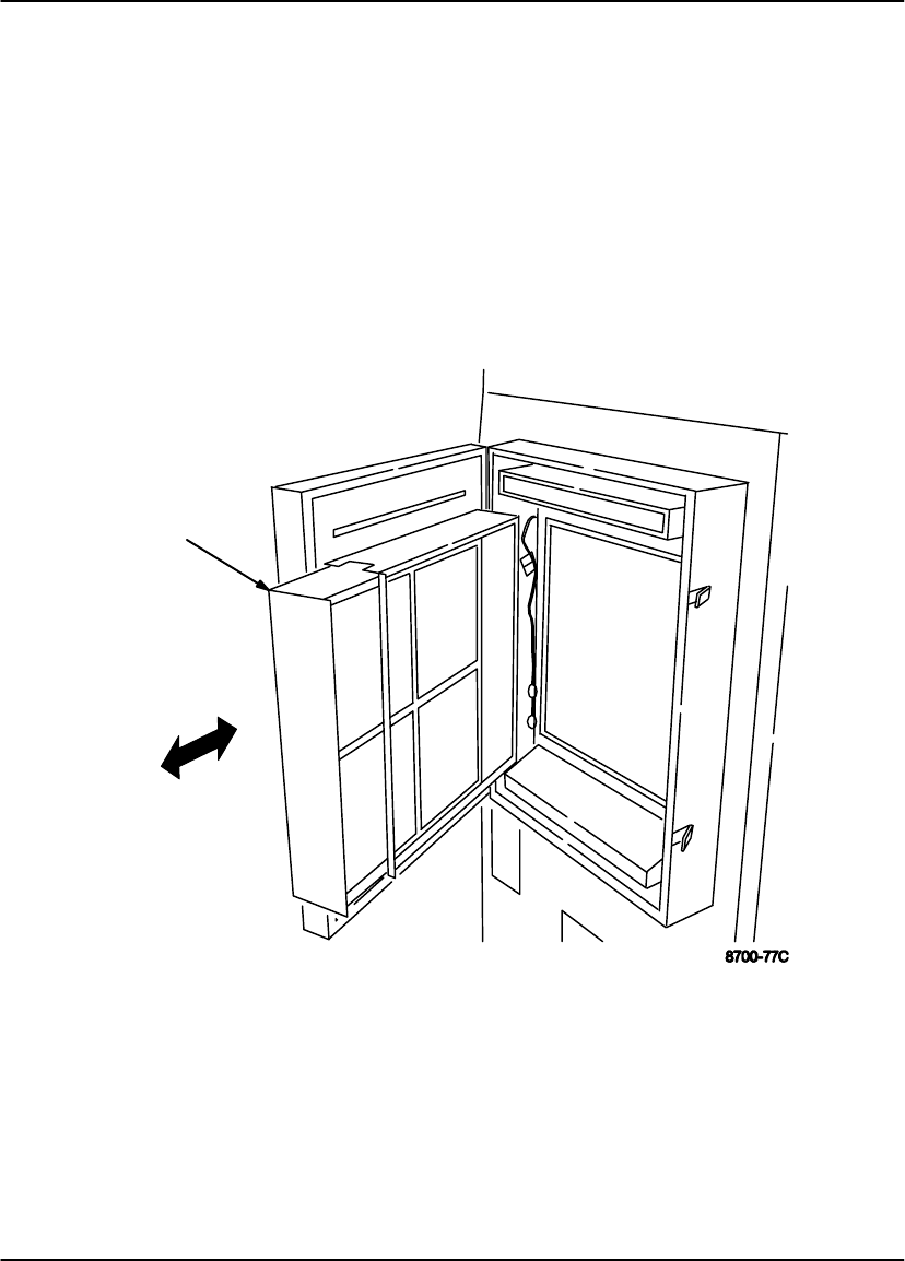
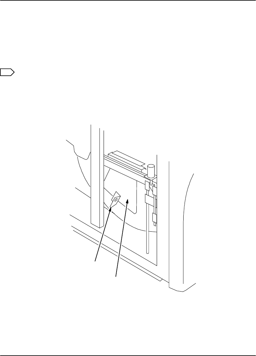
Unlocking the Left Door and Supply Door Via Mechanical Releases
Note
When the left door is unlocked via its mechanical release, the film cartridge stays
open, and the top sheets of film in the cartridge are exposed. To minimize the
number of exposed sheets, darken the room before opening the left door.
Left Door
The imager automatically unlocks the left door if a film jam occurs in the expose or
transport areas. If the imager cannot unlock the door, the local panel displays a
P208 error message. If this occurs, unlock the left door by lifting up the mechanical
release located below the left side of the imager.
Supply Door
The imager automatically unlocks the supply door when the film cartridge is empty or
when Supply is pressed on the local panel. If the imager cannot unlock the door, the
local panel displays a P229 error message. If this occurs,unlock the supply door by
pushing in the mechanical release located inside the left door.

Troubleshooting
4-15
2001 March Rev. B 8599110
Supply Door Release
Left Door Release
Figure 4-8. Left Door and Supply Door Mechanical Releases

User Guide
4-16 8599110 2001 March Rev. B
BLANK PAGE

Specifications
5-1
2001 March Rev. B 8599110
Specifications
Dimensions
Height: 1279 mm (50.4 in.) – Top Cover closed
1641 mm (64.6 in.) – Top Cover open
Width: 661 mm (26.0 in.) – Left Side Door closed
1218 mm (47.9 in.) – Left Side Door open
Depth: 813 mm (32.0 in.) – Supply and Filter Doors closed
1392 mm (54.9 in.) – Supply and Filter Doors open
Weight: 250 kg (550 lbs)
Electrical
Voltage: 200/220/240 VAC " 10%
50/60 Hz " 3%
Current Draw: 9 Amperes (maximum)
Power Consumption: 2000 V.A. (maximum)
Operating Environment
Temperature: 15° to 35°C (59° to 95°F)
Humidity: 20% to 85% RH, Noncondensing
Vibration: 0.01 Gs (maximum)
Magnetic Field: v 100 Gauss
Environmental Effects
Heat Load: 300 BTU/Hr (average)
Floor Load: 220 lb/ft2 (1065 kg/m2)
Acoustical Noise: 55 dB at one meter (70 dB momentarily)

User Guide
5-2 8599110 2001 March Rev. B
DryView 8700/8500 Laser Imager Storage Environment
Temperature: –35° to 60°C (–31° to 140°F)
Humidity: 10% to 90% RH, Noncondensing
Host Control
RS232 or RS422 (jumper selectable) connection to imager or UKEIB.
Can be located up to one kilometer (3280 feet) from imager when using a
UKEIB and fiber cable.
DryView 8700/8500 Keypad
Available image formats include 1:1, 2:1, 4:1, 6:1, 9:1, 12:1, 15:1 and 20:1.
Images are acquired and stored in sequential order, from left to right and top
to bottom.
Can be located up to 60 meters (198 feet) from imager (copper cable).
Kodak Keypad
Nine fixed formats are available – (1:1, 2:1, 4:1, 6:1, 9:1, 12:1, 15:1, 16:1
and 20:1).
Up to four custom formats can be set up. Custom formats (also referred to as
mixed formats) are set up by service personnel based on operator input.
–For 8700 and 8500 Standard and Plus systems, images within each row
must be all the same size. Image size can vary from row to row.
–For Multi–Input/Dual Printer systems, the images can be different sizes
and randomly arranged on the film.
Images can be acquired and stored in random or sequential order.
Can be located up to one kilometer (3280 feet) from imager (fiber cable).
Technical Information
6-1
2001 March Rev. B 8599110
Technical Information
Description
Kodak DryView Laser Imaging (DryView Laser Imaging) film is a high-resolution,
infrared-sensitive, photothermographic film designed specifically for the family of
DryView Laser Imaging systems.
DryView Laser Imaging film delivers the same diagnostic image quality you get with
your current silver halide laser films – but it requires no “wet” chemistry, no “wet” film
processors, and no darkroom procedures. This means there is no need for special
plumbing, wet chemistry disposal procedures, or modifications to your facility.
DryView Laser Imaging film is packaged in daylight load packages and is available
in 14” x 17”, 11” x 14”, and 8” x 10” sizes. All sizes are available in blue or clear, 7 mil
polyester base.
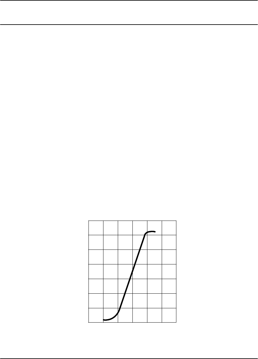
Spectral Sensitivity
DryView Laser Imaging Film is infrared sensitive and has been sensitized to the
infrared laser diode of DryView Laser Imaging systems. When handled according to
instructions on the film package, safelights are not needed. It is not recommended,
but if you remove undeveloped film from the daylight load package, you will need a
darkroom setting and a green safelight, such as the Kodak IR Safelight.
Sensitometric Characteristics
RELATIVE LOG EXPOSURE
0 0.5 1 1.5 2 2.5 3
0
0.5
1
1.5
2
2.5
3
3.5
DENSITY

User Guide
6-2 8599110 2001 March Rev. B
Image Quality
DryView Laser Imaging film delivers diagnostic-quality, continuous-tone images
along with sharp alphanumerics and optimum contrast. This high-quality silver-based
film provides radiologists with the same diagnostic information they are accustomed
to viewing – including the spatial resolution, contrast, and gray levels. Plus, because
it is a totally dry imaging process, there is no image quality variability due to “wet”
chemistry.
Automatic Image Quality Control
DryView Laser Imaging film is system-matched for Kodak’s unique Automatic Image
Quality Control (AIQC) technology. This fully automated system, which is a standard
feature of DryView Laser Imaging systems, is designed to ensure that contrast,
density, and other image quality parameters meet preset user preferences,
film-to-film, lot-to-lot.
When using the Kodak DryView 8700/8500 Laser Imager, information on each film
cartridge will allow the system to automatically determine film type, the number of
sheets remaining, and the film manufacturing lot. The AIQC uses this information to
automatically calibrate the imager’s electronics and optimize image quality without
operator intervention.
The AIQC also reads a special density patch printed on each 14” x 17” or 11” x 14”
sheet of DryView Laser Imaging film as it passes through a built-in densitometer.
Slight density variations are corrected automatically.
Technical Information
6-3
2001 March Rev. B 8599110
Less Impact on the Environment
Disposal regulations and procedures for “wet” processing chemistry are
time-consuming and expensive. And even with the most exacting procedures, the
potential to discharge hazardous materials into the environment exists.
Tests show that DryView Laser Imaging film is not considered hazardous to the
environment. As a result, you can develop, recycle, and dispose of films with less
impact on the environment than if you were using wet developed silver halide films.
DryView Laser Imaging Film
Environmental Regulations Comparison
Wet Silver Halide DryView
Developer Fixer Wash Film Film
Product
Regulation
OSHA
DOT
Use Permits
MSDS
Hazardous
Local
MSDS
Hazardous
Local
Not Required
No Limits
None
Not Required
No Limits
None
Provided
No Limits
None
Disposal *
Regulation
EPA
DOT Hazardous
Hazardous Hazardous
Hazardous No
No No
No No
No
Note: There is no SUPERFUND liability with DryView Laser Imaging Film.
* State and local laws vary. Consult appropriate regulations or authorities prior to disposal.

77°F
41°F
25°C
5°C
TEMP
User Guide
6-4 8599110 2001 March Rev. B
Storage and Handling of Undeveloped Film
As with other laser imaging films, to achieve consistent
results up to the expiration date indicated on the film
package, DryView Laser Imaging film must be stored
in a cool, dry place (41°F/5°C to 77°F/25°C) and
protected from radiation and chemistry fumes.
The film can also withstand short-term temperature spikes (up to 95°F/35°C for
several hours) during transit without any significant effect on film quality or
performance. Transit temperatures above 95°F/35°C will gradually diminish shelf life.
If the Kodak Automatic Image Quality Control system (AIQC) encounters film that
has been damaged by improper handling, it will automatically alert system operators
before the film is developed.
Handling of Developed Film
Like other photographic films or data storage materials, the handling of DryView
Laser Imaging film requires reasonable care. Spills, humidity, and other moisture
typically have no significant effect on developed films. Prolonged exposure to
intense light or excessive heat (130°F/54.4°C for more than three hours) may cause
some gradual darkening of images. Leaving films in vehicles in hot climates for
extended periods of time is not recommended.
Under typical working conditions, DryView Laser Imaging film will maintain
diagnostic quality for over 30 years. For best results, store film in sleeves when not
being reviewed. DryView Laser Imaging film can be left on a light box for more than
24 hours; in extreme cases in which light boxes are exceptionally hot (120°F/49°C),
we recommend removing them prior to eight hours of continuous exposure.
Care should be taken when using spotlight viewing for more than 30 seconds,
because temperatures near the light source may exceed 180°F/82.2°C. Use in slide
projectors is not recommended due to the high temperatures generally found in
these devices.
With Kodak DryView technology, a small amount of final development occurs when
the film exits the DryView Laser Imager and is initially exposed to ambient or view
box lighting. This is virtually undetectable and has no effect on image quality (i.e.,
less than 0.02 change in density). This small density increase is uniform and
permanent upon full exposure of the film under normal handling conditions (i.e.,
room light or view box).

Technical Information
6-5
2001 March Rev. B 8599110
Archivability of Developed Film
DryView Laser Imaging film has been tested and can be archived for more than 100
years when stored at American National standards Institute (ANSI) recommended
storage conditions (77°F/25°C). Developed films may be stored at higher
temperatures, however, that may reduce the number of years the film can be stored.
For example, storing films at a constant elevated temperature of 90°F/32.2°C may
reduce archive capability to 30 years.
Exposure to Moisture
While moisture can damage traditional wet processed silver halide films, DryView
Laser Imaging films typically withstand humidity, spills, and other forms of water
without any significant effect on image quality or film integrity. If needed, films can be
cleaned with a clean, damp cloth.
Odor Dissipation
The “wet” chemistry associated with the development of silver halide film creates
strong, unpleasant odors. By eliminating “wet” chemistry, Kodak DryView
technology eliminates virtually all of these odors. While some low-level odors are
produced during the development process, they pose no known adverse health
risks. Processing odor levels are further reduced by a non-hazardous, recyclable
filter in DryView Laser Imaging systems. This filter traps most low-level odors and
prevents them from dissipating into the work environment. To help maintain optimum
performance, the filter requires periodic replacement as specified in the DryView
Laser Imager User’s Manual. Unlike silver halide systems, DryView Laser Imagers
require no special venting.
Heat Dissipation
DryView Laser Imaging systems use a controlled amount of heat to develop
DryView Laser Imaging films. The heat has virtually no effect on the air temperature
of the work area. The amount of heat dissipated into an area during a day is typically
less than the heat generated by four 100-watt light bulbs.

User Guide
6-6 8599110 2001 March Rev. B
Film Recycling
According to the Environmental Protection Agency (EPA) standards, DryView Laser
Imaging film is not considered hazardous – so unlike typical “wet” films, it requires no
special disposal procedures. DryView Laser Imaging film does contain silver and
polyester that may be recovered by using one of several recycling processes.
If you are interested in recycling and silver recovery, Kodak can provide your local
recyclers with the information they need to get started. In some countries, Kodak has
established national contracts with recycling firms. Call your local Kodak sales
representative for more information about these contracts.
IMPORTANT NOTICE TO PURCHASER
THE FOLLOWING IS MADE IN LIEU OF ALL WARRANTIES EXPRESS OR
IMPLIED. If Kodak’s Health Imaging film products are proved defective, the user’s
exclusive remedy will be, at Kodak’s or seller’s option, to replace the defective
product or refund the purchase price.
EXCEPT FOR THE REPLACEMENT OR REFUND REMEDIES, KODAK AND
SELLER ARE NOT LIABLE FOR INDIRECT, INCIDENTAL, OR CONSEQUENTIAL
DAMAGES, REGARDLESS OF LEGAL THEORY ASSERTED, INCLUDING
NEGLIGENCE AND STRICT LIABILITY.
The foregoing may not be altered except by written agreement signed by an officer
of Kodak and seller. All customer orders are subject to above terms of sale,
notwithstanding conflicting terms on orders.