Eastman Kodak 870085007E2620 Medical Laser Imager User Manual ug8700
Eastman Kodak Company Medical Laser Imager ug8700
UserManual.wiki
>
Eastman Kodak
>
870085007E2620 User Manual
>
draft user guide
Contents
1.
Draft user manual
2.
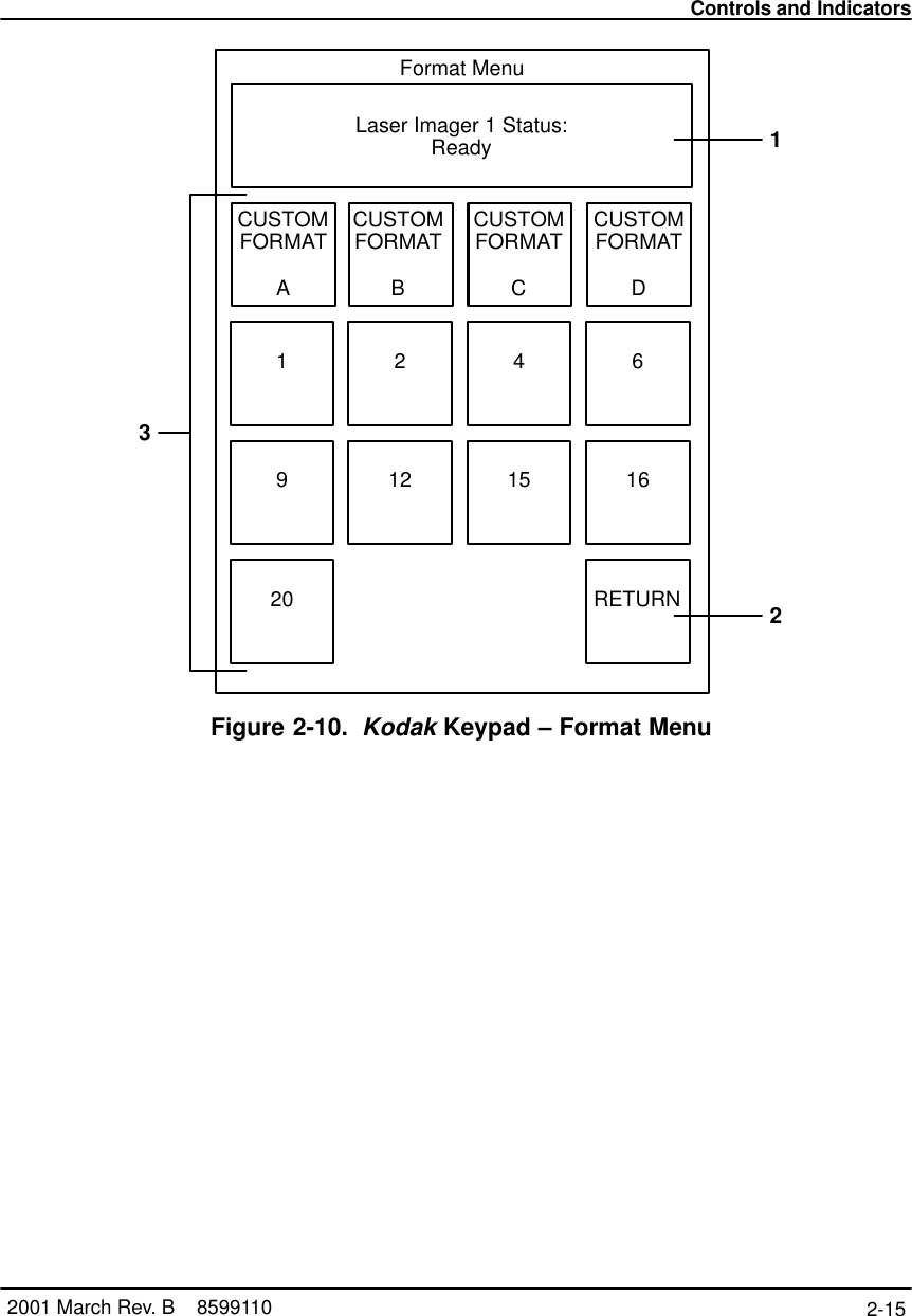
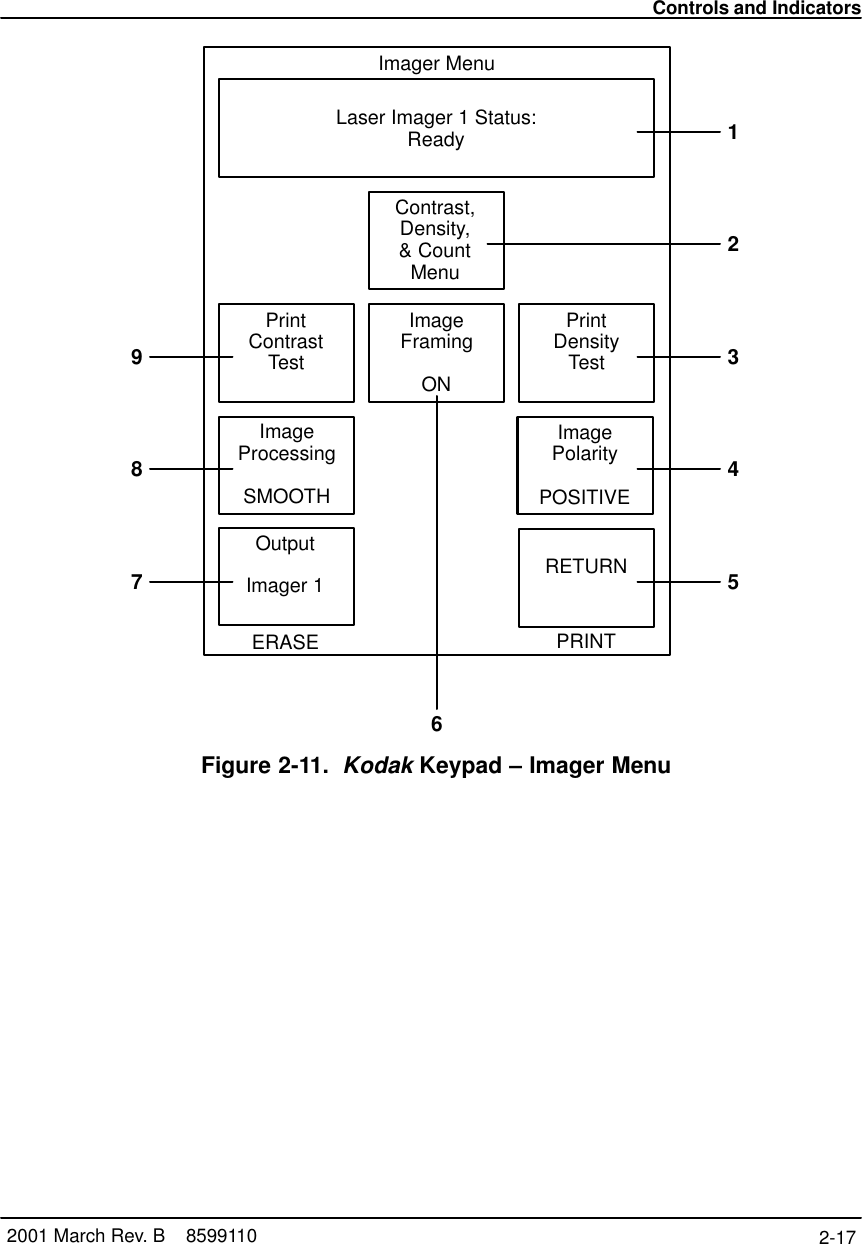
draft user guide
draft user guide
Navigation menu
Upload a User Manual
Namespaces
Wiki Guide
HTML
PDF
Info
Views
User Manual
Discussion / Help
Navigation