Easy Radar USA ER500A Ground Penetrating Radar User Manual ER500A Manual 7 28 17
Easy Radar USA LLC Ground Penetrating Radar ER500A Manual 7 28 17
Contents
- 1. User Manual
- 2. Infosheet for customer
- 3. Usermanual
Usermanual

Manual for Ground Penetrating Radar model: ER500A
FCC ID: 2AJAHER500A
7-28-2017
EASY RADAR USA LLC 237 IMPLEMENT ROAD AIKEN SC (803) 761-3699

FCC Class B Compliance
This device complies with Part 15 of the FCC Rules. Operation is subject to the following two conditions:
(1) this device may not cause harmful interference, and (2) this device must accept any interference received,
including interference that may cause undesired operation.
Warning: Changes or modifications to this unit not expressly approved by Easy Radar USA LLC can void
your authority to operate this equipment under Federal Communications Commission rules.
Note: This equipment has been tested and found to comply with the limits for a Class B digital device,
pursuant to Part 15 of the FCC Rules. These limits are designed to provide reasonable protection against
harmful interference when the equipment is operated in a commercial environment or residential installation.
This equipment generates, uses, and can radiate radio frequency energy and, if not installed and used in
accordance with the introduction manual, may cause harmful interference to radio communications. However,
there is not guarantee that interference will not occur in a particular installation.
Shielded USB cable must be used with this unit to ensure compliance with the Class B FCC limits.
SOFTWARE INSTALLATION:
1.
DISCONNECT THE GPR from the PC, AND SWITCH IT OFF (if switched ON and/or connected to the PC)
2.
Please, download the software .zip packages
3.
Unpack the DRIVER CP210x_VCP_Windows.zip package on your desktop, and the proper installer (for 32or
64-bit Windows)
4.
When finished with the installation of the drivers, plug the GPR's USB into the USB port of the PC
5.
Open Device Manager and check in COM Ports Section for a device 'Silicon Labs CP210x USB to UART Bridge
(COM?)', where ‘?’ is the Com Port the GPR will use. If, for some reason, the number of the COM port is above
10 or higher, open COM port's properties, Port Settings Tab, Advanced, and change COM Port Number to a
number below 10.Also, in rare cases (usually when there are Bluetooth units being used, or have been used
on this PC), COM ports below 10 may be stated as 'in use'. Since we are not going to use a Bluetooth device
and the GPR simultaneously, we intentionally change the COM port number of the Silicon Labs CP210x USB to
UART Bridge to a number below 10. After that, we unplug the USB cable from the PC and plug it back in. This
time, the COM port of Silicon Labs CP210x USB to UART Bridge should be changed to the desired COM Port
Number (below 10).
6.
Unpack the Main GPR Program's archive (EASYRAD_098_ENG_20130901.ZIP) on (for example) your
Desktop, and start the GPR Program.
7.
Upon start, the Program may show you some warnings about the COM Port it needs to use, but after you
close these warnings messages, you will have to change the COM Port Number that your GPR Device will use.
8.
Initially, the GPR Program starts in GPR Mode (I.e., it will use the GPR right away), but you may also switch
to Demo Mode and train yourself working with the Program, using the Data File (EASYGPR.SGY) provided with
the Program's package.
9.
When you decide to use the GPR (GPR Mode), upon start working, you do the following steps:
Each time you want to work with the GPR, you do the steps from 9.1 to 9.8 in this very order.
9.1) Switch the GPR OFF
9.2) Plug the USB Cable in USB Port of the PC (you should hear a sound once the OS recognizes the GPR).
9.3) Start the GPR Program
9.4) Check (and change if needed) the COM Port you are about to use with the GPR
9.5) Switch the GPR ON
9.6) Click on Start (or press 'Z' on keyboard)
..... Work with the GPR
9.7) Switch the GPR OFF
9.8)
Leave (exit) the GPR Program (Upon exit, the GPR Program will save all its settings, and next time you
start the GPR Program, it will use them - COM Port, Gain Settings, Color Palette, etc.)
9.9)
(Eventually) Shut the computer down (Not necessary, if you are about to do more with it).
CHAPTER 1
Installing USB-to-COM Port Serial Bridge
This chapter demonstrates how to install the GPR software drivers on your computer operating system.
Although it depicts how you should do it on Windows 7 OS, it applies to Windows XP and Windows 8 as well.
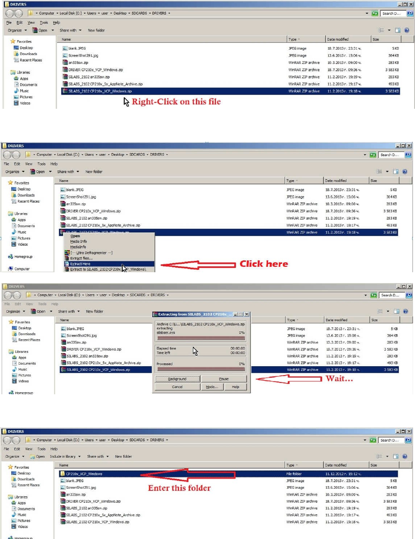
1. When you have the drivers package downloaded on your computer, open the containing folder and do
the following steps in order to install the drivers.
2. Extract the archive
3. Open the subfolder, that contains the drivers
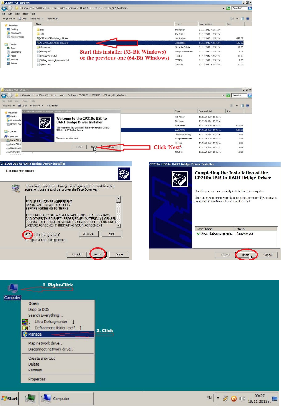
4. Start the installer, depending on your Operating System: 32 or 64-bit
5. Follow the Installer’s instructions
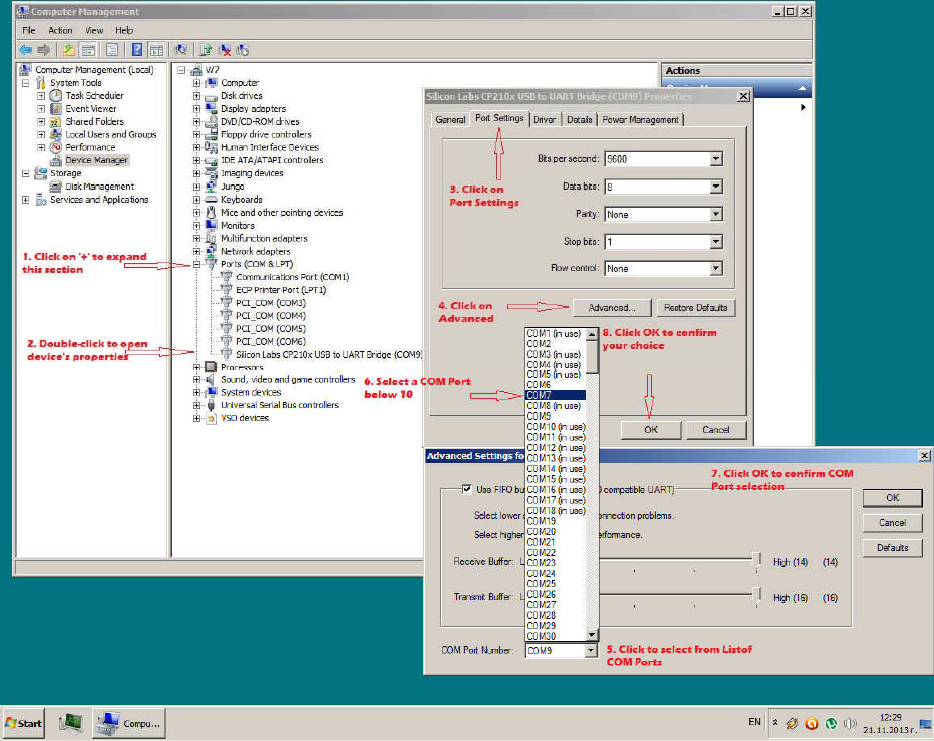
6. When Installer finished, go to Desktop and Right-Click My Computer and Click to select Manage.
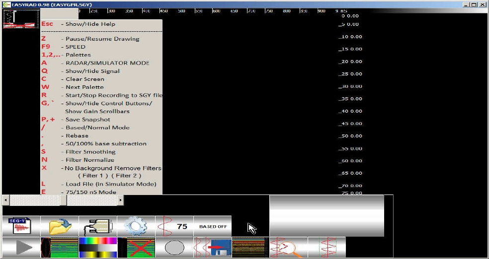
7. If GPR COM Port number is above 10, you need to change it to a number below 10. If its number is below 10,
leave it as it is.
CHAPTER 2
In this chapter we will get to know how to work with the GPR program.
It is for the best if you have the GPR program on your computer’s Desktop. The GPR program must be placed on a
writable media (HDD/flash drive) and must not be placed on a non-writable media such as CD-ROM or DRV-ROM,
because it would need to store information on the disk, where it has been started from.
The program consists of 3 (three) files:
1. The executable file (.EXE),
2. The Configuration File (.CFG) containing settings and parameters,
3. The demonstration File (a .SGY file, made while working with a GPR).
You should know that all the files you are going to create during working with the GPR and the program will be
stored in the same folder (for example the Desktop and subfolders as 20130713, 20130714, etc.)
Providing we have already installed the communication drivers (USB-to-Serial Com port drivers) (See Chapter I –
Installing the Device Driver), we may proceed to start working with the GPR. First we need to connect the GPR to the
PC, i.e. we need to plug the GPR’s USB cable into a free USB port on the PC. Note that at this moment the GPR may
be switched ON or OFF, but still we recommend you at this very moment you better keep it switched OFF (in very
rare occasions, the Operational system (Windows XP/7) may misrecognize the GPR as a mouse and would start
acting weirdly).
After plugging the USB into the PC, we should hear a sound that indicates computer has recognized the GPR’s USB
communication dongle. Now we are ready to start the GPR program and work with the GPR. Find the GPR Program’s
icon on your Desktop (or where it is located) and double-click it.
Upon start, the GPR Program shows its Control Panel and the help window (describing the control keyboard keys).
You may hide/show the help window using key ESC.
(fig. 1)
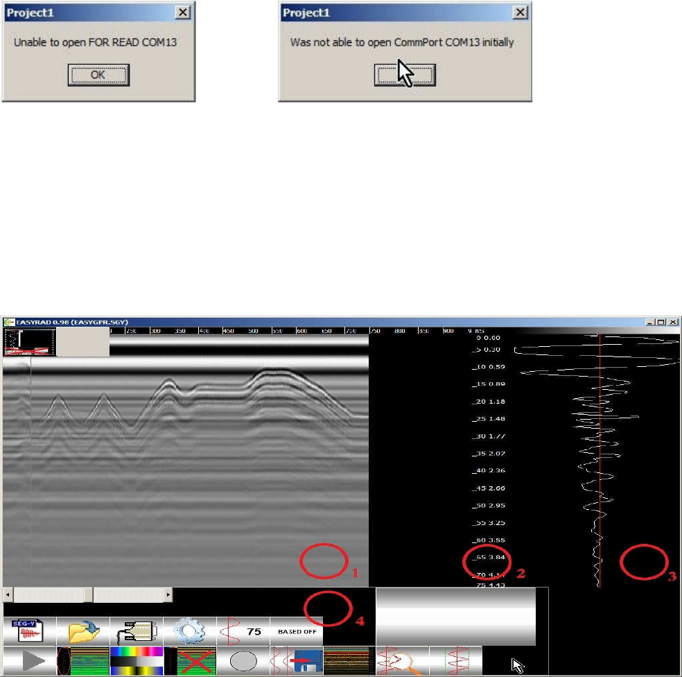
Sometimes, when you start the GPR Program, it shows messages, that it could not find the last COM port used:
followed by: (fig. 2)
You click “OK”, and will have to manually select the COM port to work with (see Troubleshooting, fig. 13)
GPR Program’s window consists of 4 (four) regions:
1. Here is the Radar gram as a result of consecutive radar signals drawn;
2. Panel with Depth information;
3. Signal Curve Panel. Here the signal curve is shown;
4. Control Panel. Contains control buttons, scrollbars, settings, etc.
(fig. 3)
You may show/hide Panel 3 (one containing the signal curve) using the corresponding button in the Control Panel or
by pressing ‘Q’ key on keyboard. Hiding the Signal Curve panel, you can see more of the Radargram Panel.
In panel 1 you see the radargram, i.e. the result of the latest incoming radar signal data. The radargram shows the
incoming radar data, filtered and processed by the desired data processing filters and settings.
Control Panel: there are many buttons on the Control Panel. You may click on them and control GPR and Program’s
actions, using filters, recording data, etc.
Almost every button on the Control Panel has its keyboard substitute, i.e. you may control Program’s actions by
mouse clicking on screen buttons OR by pressing keys on keyboard.
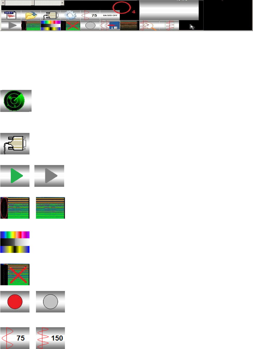
The GPR Program’s Control Panel is situated in the Bottom Pane. It contains several buttons, scrollbars, etc. which
you may use to navigate the GPR Program, change settings, using filters, choosing files to simulate, choosing COM
Ports to communicate with the GPR, etc.
You can interact with the Program by mouse-clicking on program’s Control Panel buttons or pressing keys of the
keyboard.
Button (A) MODE -(Key ‘A’). Selects Mode of operation: Radar or Simulator Mode. This icon
shows the selected operation mode you selected. In RADAR Mode, the program uses the GPR as
data source; in SIMULATOR Mode it uses a pre-recorded data file to simulate. When using
SIMULATOR, the Load File (key ‘L’), is allowed in order to select a Radargram File (.SGY file) from your computer and
simulate it.
Button COM Port - You may choose the COM Port the GPR communicates with the PC and the
Program.
Button (Z)PAUSE -(Key ‘Z’).Starts/Stops receiving data from the GPR (start/stop
showing simulated data from file).
Button (Q) Signal -(Key ‘Q’). Shows/Hides Signal Curve Panel on program’s
window.
Button [W] Palette -(Key ‘W’). Changes Color Palette.
Button (C )Clear -(Key ‘C’). Clears the radargram and starts receiving data from the GPR.
Button (R )Start/Stop Recording -(Key ‘R’). Start/Stop recording the radar
data to a file on the PC. Filenames are in the following format:
year_month_day_hour_min_sec.SGY – the time of creation of the file. Ex:
20130710_231029.SGY – 10 July, 2013, 23:10:29 h.
Buttons 75nS , 150nS -(Key ‘E’). Using these buttons (or key ‘E’) you choose the
‘length of the time window’ (in nanoseconds) the GPR works on. This defines the
depth of the scanning. In 150nS time window the GPR scans in FULL depth, as where
as in 75nS time window it scans in HALF time window/half depth respectively.
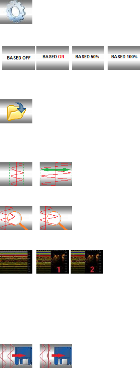
Button Set Soil Type - You may choose the presumable soil type that the GPR works on. Different
soils reflect, absorb, etc the radio-waves differently, and allow different depth of penetration of the
GPR radio-waves in them. They also affect the signal’s form/amplitude in different ways/degree. This
way it is possible to determine presence of different layers of soils, voids, objects and their (presumable) depth.
Button 100%, Based - You choose Base Filter (and
degree of applying it). The incoming data is being
compared with a base signal, taken at the moment of
start using the filter. Key ‘/’ starts/stops using the filter.
Key ‘.’ takes a new base signal to compare with. Key ‘,’ changes the degree of applying the Base Filter (50%, 100%).
Button Open File -(Key ‘L’). In Simulator Mode, you may open a previously saved .SGY file and
visualize/simulate.
FILTERS:
Normalize -(Key ‘N’). You should use this filter when you have weak
Radar signals. This filter would enhance signal’s amplitude for better presentation of
signal changes of incoming signal/data.
Smooth -(Key ‘S’). „Smoothing” the incoming signal/data. When you
apply this filter, it removes high frequency components of the signal/data.
Remover Filters (Off, 1, 2) - (Key ‘X’). These filters are probably the
most often used filters. When No Remover Filter is used, you will see
the original Radar Signals drawn onto the Radargram. When Remover
Filter 1 or 2 is selected, the software applies algorithmic and computational methods in order to clarify the
Radargram’s image and show as much as possible significant and useful information out off the GPR’s data. When
Remover Filter 1 or 2 is selected, the software applies 2 similar, yet different methods to remove the “carrying form”
of the signal, and leaves only changes and differences between the consecutive scans and that way shows objects
and layers beneath the ground surface. Remover Filter 1 and 2 give better results in combination with ”Smooth”
Filter and Normalize Filter.
Original / Modified Data -When recording the GPR data, you may choose to
either save it ‘as it is’ or save it ‘as it is shown’, i.e. to either store the GPR data in its
original form (despite the current settings of the Filters, Gain controls, etc.) OR after
applying all the filters and settings selected. It is recommended you to store (record) the incoming data in its original
form, in order to analyze/edit the data using other SGY data viewers/editors, etc..
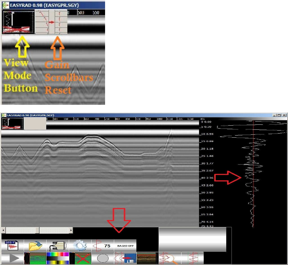
Gain Scrollbar Reset Button: Resets all the Scrollbars (Hardware
Amplifier Scrollbar, Zonal Software Amplifier Scrollbars, and Contrast
Scrollbar to their Initial settings.
View Mode Button: Clicking on this button or using keyboard key “G”
or “ ` ” you choose one of three possible views of the program’s
window: (fig. 4) (fig. 5) (fig. 6)
(fig. 4) With Control Panel and Curve Panel visible
Visualization Mode 1: When you press Key ‘G’ for a first time, you will see the Zonal Gain Control Scrollbars at the
place of the Signal Pane . There are 5 Scrollbars, each controlling a subzone (from top to bottom of the signal) and
are able to (Software) amplify the signal from 0% до 400%. There is also a Button Gain=1, which puts all 5 Zonal Gain
Scrollbars in equal (100%) position. It also sets the Hardware Amplifier Scrollbar and Contrast Scrollbar to their
default Initial
settings.
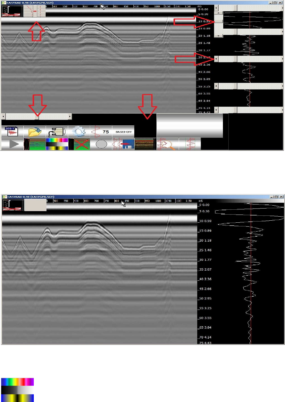
(fig. 5) With Control Panel, Curve Panel and Gain Scrollbars visible
Visualization Mode 2: When you press Key ‘G’ for a second time, the program hides the Zonal Gain Control Scrollbars
and the Program Control Panel for a clean Radargram and/or Signal view.
(fig. 6) With no Panels visible
Visualisation Mode 3: When you press Key ‘G’ for a third time, the program shows back the Control Panel.
Color Palette selection. By pressing keys ‘1’ to ‘9’ you choose one of 9 pre-defined color Palettes,
used to represent the Radargram. There are color and black/white Palettes to choose from, and you
may use one that suits you best. Black/White (Grey shade) Palettes are recommended, since they are
easier to comprehend.
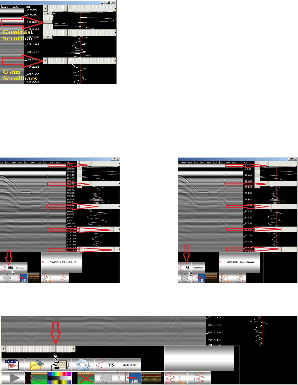
SCROLLBARS: Gain Scrollbars, Hardware Amplifier Scrollbar, Contrast Scrollbar
(fig. 7)
Contrast Scrollbar: It serves for Contrast Adjustment of the Radargram.
Zonal Gain Control Scrollbars: They serve for zonal (from top to bottom, 5 zonal) amplitude control (amplification) of
the signal. You may amplify certain zones of the signal curve (usually the lower part of it, which corresponds to
bigger depth) in order to emphasize the changes of underground content while doing a survey. Note, that you have 2
different sets of settings (Zonal Gain Control, Contrast, Hardware Amplifier) for half-depth scanning (75 ns) and full
depth-scanning (150 nS). (fig. 8)
Zonal Gain (fig.8)
There is a Hardware Amplifier in upper left part of the Control Panel. It controls a hardware signal amplifier, built in
the GPR. It has 5 degrees of amplification. Using the Button next to the Gain Scrollbar sets the hardware amplifier to
its middle degree. (fig. 9)
(fig. 9) Hardware Amplifier Scrollbar
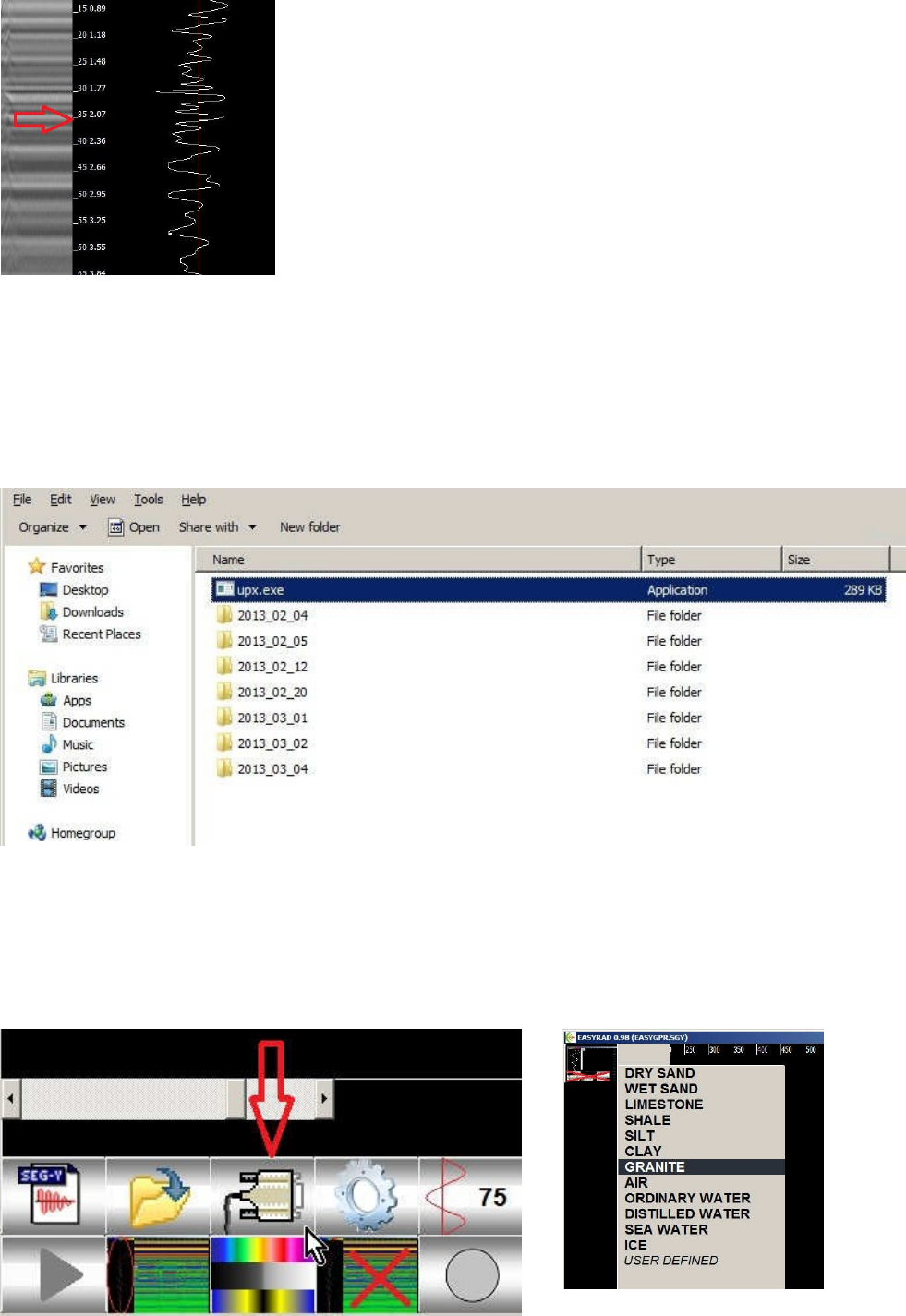
There is a Time/Depth Panel between the Radargram Panel and Signal Curve
Panel. It shows a scale in nanoseconds and depth in meters (depending of soil
setting and presumed soil conditions). You may mouse-click on the Radargram
and see depth of the pointed object. (fig.10)
(fig. 10)
Making a snapshot of program’s window:
Key ‘P’, Key ‘+’ - Saves a snapshot of the current screen content as a .BMP (BitMap) file format in Current
date’s Folder. You should know that all the files you are going to create during working with the GPR and the
program will be stored in the same folder (for example: the Desktop and subfolders as 20130713, 20130714, etc.)
(fig. 11)
Selecting a Soil Type
(fig.12)
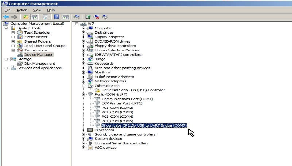
If, for some reason, there is no COM Port List, or the Com Port you normally use is not listed, you may
need to close the Program, unplug the USB Cable and do the following:
1. Turn the GPR OFF
2. Plug the USB cable into the PC (you should hear a sound when the PC recognizes the GPR)
3. Start the GPR Program again
4. Do Select a Com Port again
If you are unsure why the Program does find the Com Port, you may check its presence in the
Computer Configuration by Opening PC’s Control Panel (Manage):
1. Right-Click On My Computer’s Icon on PC’s Desktop
2. Click on Manage and click On Device Manager
3. Click On Ports
4. Check for USB-to-Serial Bridge Device
For more detailed information on how to set the GPR COM Port, see at the end of Chapter 1.

For U.S. Customers
Ground Penetrating Radar Coordination Notice and Equipment Registration
Note: This form is only for Domestic United States users. The Federal Communications
Commission (FCC) requires that all users of GPR who purchased antennas after July 15th, 2002
register their equipment and areas of operation. If you have purchased any antennas after
July 15th, 2002, you must fill out this form and fax or mail to the FCC.
1. Date:
2. Company name:
3. Address:
4. Contact Information [contact name and phone number]:
5. Area of Operation [state(s)]:
---Continued on next page.

6. Equipment Identification:
Brand Name: Easy Radar USA LLC
Model Frequency
FCC ID (2AJAH followed
by Model #)
7. Receipt Date of Equipment:
Fax this form to the FCC at: 202-418-1944
Or
Mail to:
Frequency Coordination Branch, OET Federal
Communications Commission 445 12th Street, SW
Washington, D.C. 20554
ATTN: UWB Coordination
Do not send this information to Easy Radar USA LLC.