EasyIO FW14 Building Automation System User Manual
EasyIO Holdings Pte. Ltd. Building Automation System Users Manual
EasyIO >
Users Manual
EasyIOFW‐14–UserReference
1
EasyIOFW14UserReference

EasyIOFW‐14–UserReference
2
DocumentChangeLog
26thDec2016
Documentcreated.

EasyIOFW‐14–UserReference
3
Disclaimer
EasyIOFW‐14isaproductbyEasyIOHoldingsPteLtd
TheEasyIOFW‐14wasbuiltontheSedonaFramework®.
SedonaFrameworkisatrademarkofTridium,Inc.
CPTToolisbyOnlineToolsInc.

EasyIOFW‐14–UserReference
4
Federal Communication Commission Interference Statement
This equipment has been tested and found to comply with the limits for a Class B digital device, pursuant to Part
15 of the FCC Rules. These limits are designed to provide reasonable protection against harmful interference in a
residential installation. This equipment generates, uses, and can radiate radio frequency energy and, if not
installed and used in accordance with the instructions, may cause harmful interference to radio communications.
However, there is no guarantee that interference will not occur in a particular installation. If this equipment does
cause harmful interference to radio or television reception, which can be determined by turning the equipment off
and on, the user is encouraged to try to correct the interference by one or more of the following measures:
• Reorient or relocate the receiving antenna.
• Increase the separation between the equipment and receiver.
• Connect the equipment into an outlet on a circuit different from that to which the receiver is connected.
• Consult the dealer or an experienced radio/TV technician for help.
Caution: Any changes or modifications not expressly approved by the party responsible for compliance could void
the user's authority to operate this equipment.
FCC Caution:
This device complies with Part 15 of the FCC Rules. Operation is subject to the following two conditions: (1) This
device may not cause harmful interference, and (2) this device must accept any interference received, including
interference that may cause undesired operation.
FCC Radiation Exposure Statement:
This equipment complies with FCC radiation exposure limits set forth for an uncontrolled environment. This
equipment should be installed and operated with minimum distance 20cm between the radiator & your body.
RF Exposure: A distance of 20 cm shall be maintained between the antenna and users, and the transmitter
module may not be co-located with any other transmitter or antenna.

EasyIOFW‐14–UserReference
5
TableofContents
Introduction ....................................................................................................................................................6
HardwareConfigurations................................................................................................................................7
PowersupplyConnection...........................................................................................................................7
RS485Connection.......................................................................................................................................8
JumpersConfigurations ..............................................................................................................................9
Wiringdiagram .........................................................................................................................................10
DigitalOutputWiringConnection ............................................................................................................11
AnalogueInputConnection ......................................................................................................................12
AnalogueOutputConnection ...................................................................................................................14
WirelessNetwork..........................................................................................................................................15
ButtonsandIndications ................................................................................................................................15
LoginDetails..................................................................................................................................................17
ChangingIPaddress......................................................................................................................................18
Restorefactorysettings................................................................................................................................20
TechnicalSupport .........................................................................................................................................21
EasyIOFW‐14–UserReference
6
Introduction
EasyIOFWSeriesisthemostpowerfulwirelessSedonacontrollerinthemarket.Itisequippedwithtwo
32‐bitProcessors,thefirstintheAutomationindustry,witha580MHzMTKprocessorandanARMM0
CortexfortheI/OmanagementandA‐Dprocessing,andalsowithaLinux3.18OSforpremium
performance.SupportsBACnetasserverandTComorpremiumperformancewithNiagaraAXandN4.
TheBuildinbootloadercanbecarriedoutremotely.Nomoremanualservicebutton
neededisused.
Firmwareupgradingcanbedoneremotelyandwithoutanyassistant.
Firmwareupgradingisviaftpclient.
Thisdocumentdescribeaboutbasicconnectionandtechnicalspecifications.
ItappliesforEasyIOFW‐14.
Item FG‐32
DigitalOutput 2Channels
UniversalOutput 4Channels
UniversalInput 8Channels
TableshownaboveshowtheIOconfiguration
EasyIOFW‐14–UserReference
7
HardwareConfigurations
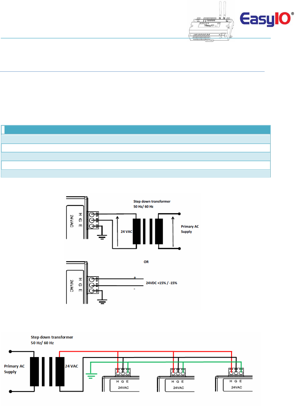
PowersupplyConnection
BothACandDCcanbeusedforEasyIOFW‐14Seriescontroller.Refertoelectricalspecificationforthe
workingrange.Inordertoavoiddamageonthecontrollerinput/outputdevicesandRS485connection,
useindividualpowersupplyforeachcontroller.Ifasinglepowersupplyisusedtopowerupmultiple
EasyIOFW‐14,makesurecontrollerpowersuppliesareconnectedwiththesamepolarity.
Electrical
Power Supply 24V AC +/- 5% or 24V DC +20%/-15%
Consumption 500 mA
Operating Temperature 32 to 150 Deg-F (0 to 65 Deg-C)
Storage Temperature -4 to 150 Deg-F (-20 to 65 Deg-C)
Operating Humidity 10% to 70% relative humidity non-condensing
PowerSupplyConnection
Multiplecontrollerssharesingletransformerconnection
EasyIOFW‐14–UserReference
8
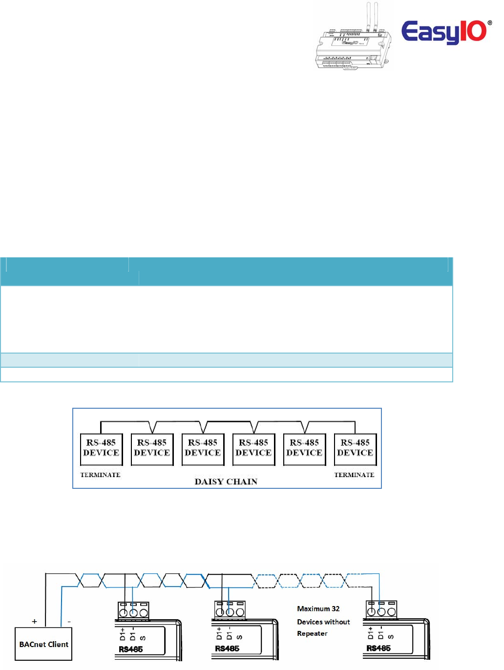
RS485Connection
RS485connectionmustbeterminatedatbothendswithterminationresistor,typically120Ohms.Itis
recommendedtouseshieldedtwistedpairwire(STP)forthewiring.
Lightningprotectioncircuitishighlyrecommendedtobeinstalledatoneendofthewiring.Thecontroller
shouldbewiredindaisychainnetworktopologyasshownasimagebelow.Ifwirebranchcanbeavoided,
keepitasshortaspossible,andneverconnectmorethanonedevicetothewirebranch(itisnot
recommended).
BecarefulifsinglepowersupplyisusedforallconnectedRS485device,makesurealldevicesare
havingthesamegroundconnection.Makesureyouareconnectingthesamewireforthesame
terminalposition,all“H”terminalsconnectedtothesamewire.
Physical Interface Remark
EIA-485
BUS A,B
Two Wire, Half Duplex
Speed:(9.6K, 19.2k, 38.4K),
Data Bit:(8 bits),
Parity:(None)
Ethernet 10/100 Mbps IP, TCP, UDP, ICMP, HTTP,FTP
Application Support Sedona, BACnet MSTP Server and Tcom
DaisyChainNetworkTopology
RS485ConnectionDiagram
EasyIOFW‐14–UserReference
9
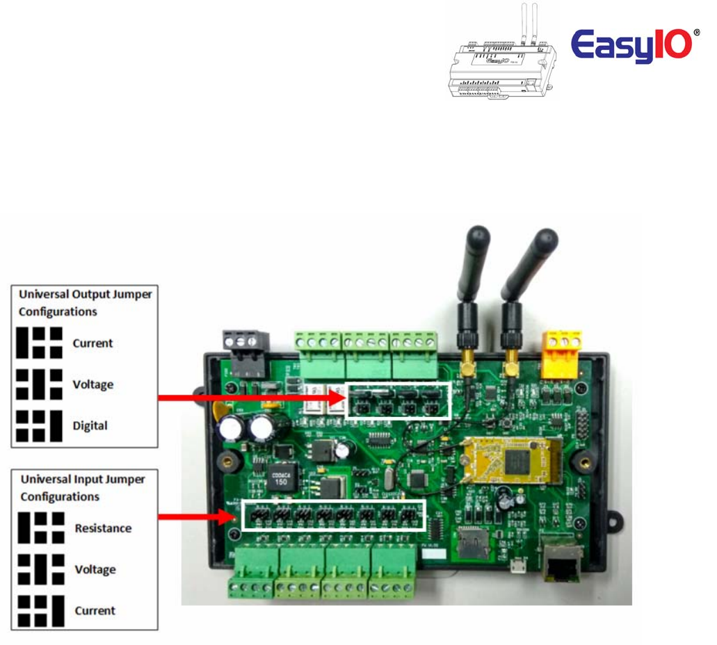
JumpersConfigurations
BelowimageshowsthejumpersettingforUniversalInput,UniversalOutput,WatchdogandalsoEIA485
120Ohmterminations.
EasyIOFW‐14–UserReference
10
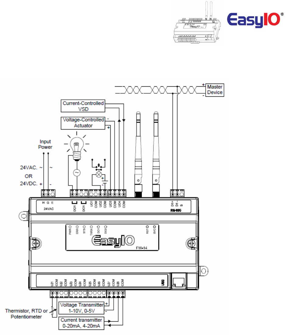
Wiringdiagram
EasyIOFW‐14–UserReference
11
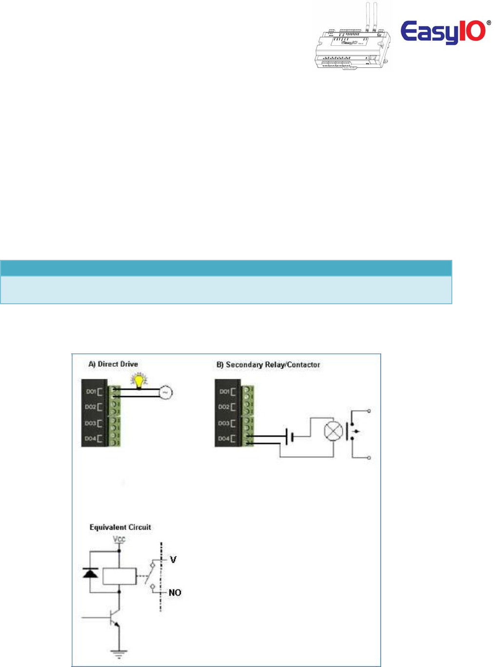
DigitalOutputWiringConnection
EasyIOFW‐14Seriesdigitaloutputisforgeneralpurposeisolateddigitaloutputconnections(relay
output).
Generalratingisasbelow(DirectDrive);
100VAC,0.5A
24VDC,2A
PilotDutyratingisasbelow(PilotDuty);
24VAC,0.5A
24VDC,0.5A
Digital Output 2 Channels
Type Relay Contacts, SPST NO, 48VA at 24VAC,
Pilot Duty at 500mA max load.
Itdoesnotoutputvoltageorcurrent.Itisadryrelaycontact.
DigitalOutputConnection
EasyIOFW‐14–UserReference
12
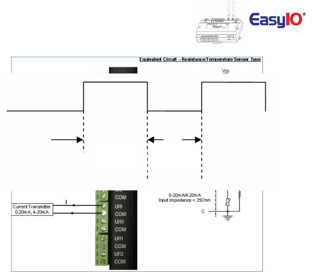
AnalogueInputConnection
EasyIOFW‐14serieshasnon‐isolateduniversalinputs.Theuniversalinputsupportsthreetypeofanalog
signali.e.resistance,voltageandcurrenttransmitterviahardwarejumperandinternalregistersettings:
Universal Input 8 Channels
Voltage 0 - 10V DC (+/-0.005V)
Resistance 500 - 500K (+/-10 Ohm)
Thermistor 10K, 10K Shunt, 1K Balco, 1K Platinum : All (+/-0.01 Deg-C)
UI as Digital Input Voltage Free Contact
a) Resistance–Theworkingrangeofresistanceis500Ohm–500KOhms.Iftheinputis
configuredasThermistortype.ThecommonlyusedThermistorlike10K,10KwithShunt,1K
Balcoand1KPlatinumareallsupported
b) Voltage–Supports0–10Vand0–5V(scalingrequired).
Theminimuminputimpedanceofvoltagemodeinputis1MegaOhm.
c) PulseInput–AllUniversalInputsarecapableofreceivinghighspeedpulse.Minimumontime
pulseis20msandminimumofftimeis20ms.
Approximately25Hz.Refertoimagebelow.
EasyIOFW‐14–UserReference
13
UniversalInputasPulseInputspecifications,Max25Hz
MinimumOn
period20ms
MinimumOff
period20ms
EasyIOFW‐14–UserReference
14
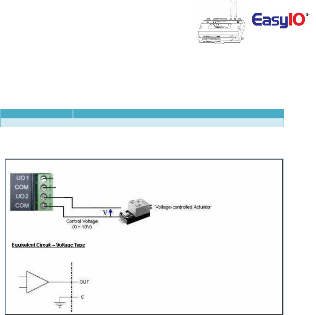
AnalogueOutputConnection
EasyIOFW‐14serieshasUniversalOutputconnections.EachUniversalOutputcanbeconfiguredtodrive
voltageorcurrentoutputordigitaloutputviahardwarejumperandinternalregistersettings.
Theworkingrangeforvoltageis0–10V.
Universal Output
4 Channels
Type
Voltage: 0 – 10VDC , Min Impedance 1000 Ohm.
UniversalOutputConnectionforVoltageandCurrent
EasyIOFW‐14–UserReference
15
WirelessNetwork
EasyIOFW‐14comeswithonboardwirelessconnection.
ItcomplytoIEEE802.11standards.
ItsupportsB/G/Nband.
Eachunitissuppliedwithtwo(2)2dBifemaleSMAjackantenna.
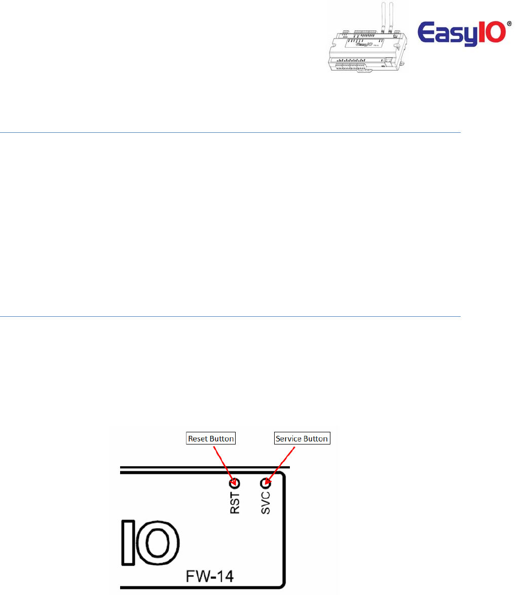
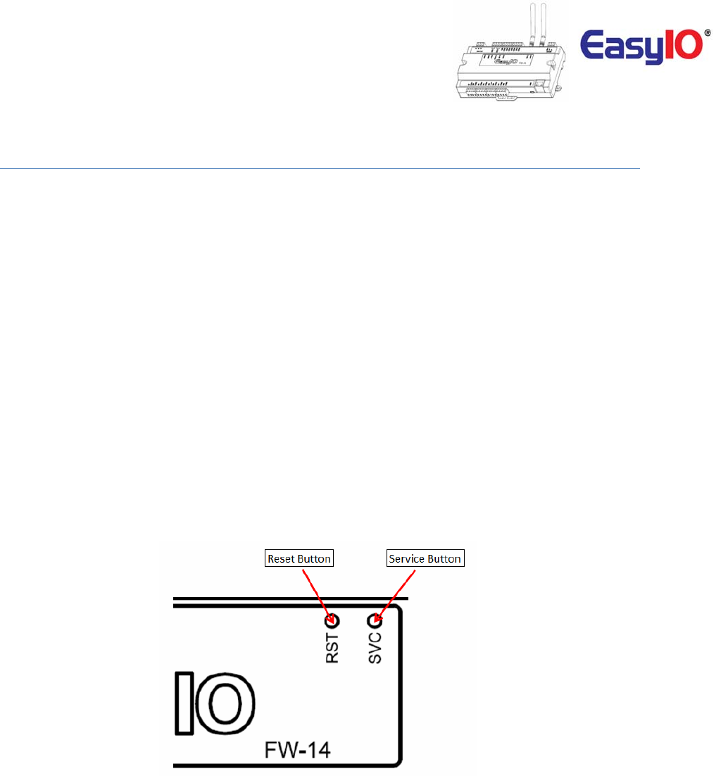
ButtonsandIndications
ThecontrollerwilldoahardwareresetwhentheResetButtonispressedwhenevermanualrestartis
required.
TheServicebuttonisusedtoactivatethebuilt‐inbootloaderprogramforsoftwareupgrade.
EachdigitaloutputhasacorrespondenceLEDtoindicateitscurrentstate.
ImageshowstheResetbutton,ServicebuttonandalsoTXRXindicators.
ImageshownisanEasyIOFW‐14unit.
EasyIOFW‐14–UserReference
16
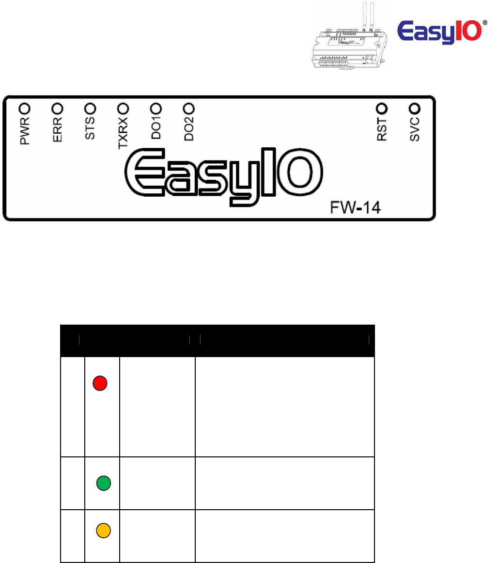
ImageshowstheStatusindicator,ErrorindicatorandindividualDigitalOutputindicator
ButtonandLEDindications.ImageshownisanEasyIOFW‐14.
LED
Conditions Description
Pattern: continuously blinking.
ERR is to indicate whenever there is
1
ERR
Communication errors.
Pattern: constantly light up.
The controller is undergoing firmware
upgrading. This is normal during firmware
upgrade process.
STS is used to indicate the heartbeat of the
Microcontroller. The STS LED will blink at
2
STS
1-second interval in normal operation
Condition.
TXRX is used to indicate when there are
Communication activities in Port 1.
3
TX/RX
(Transmitting or Receiving) on the
Communication port.

EasyIOFW‐14–UserReference
17
LoginDetails
EasyIOFW‐14Seriesdetailsareasbelow.
DefaultIPaddress
:192.168.10.14
DefaultSubnet
:255.255.255.0
DefaultGateway :192.168.10.1
Note:
Inordertologin,thehostPC(laptop)hastobeinthesamesubnet.Example:
IPaddress:192.168.10.123
Subnet :255.255.255.0
SedonaLoginviaCPT
Username :admin
Password :<nopassword>
EasyIOFW‐14–UserReference
18
ChangingIPaddress
BydefaulttheEasyIOFW‐14seriescontrollerIPaddressis192.168.10.14.
ChangingtheIPaddresscanonlybedoneviaCPTTool.
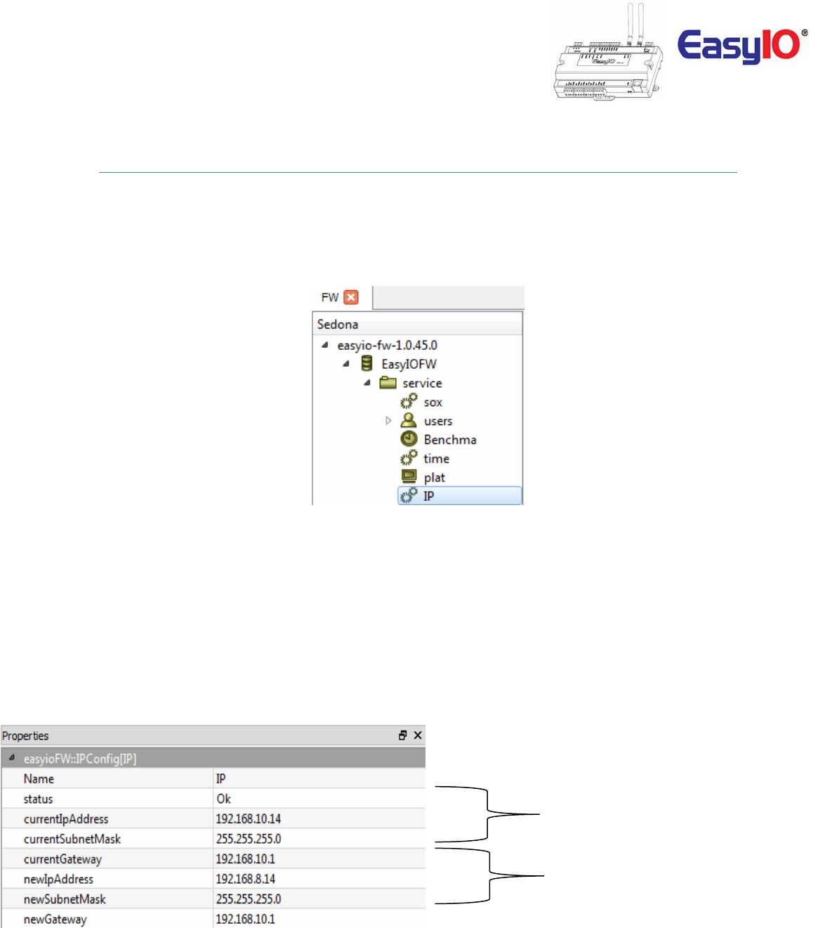
Step1
LogintotheFW‐14viaSedonaworkbench.Locatetheobject“IP”undertheSedonaservicefolder.
Step2
Gointothepropertysheetofthe“IP”object.
CurrentIPaddressthatis
assigntothecontroller
NewIPaddressfield.Keyin
therequiredIPaddressin
thesefields.MakesuretheIP
addressandsubnetiscorrect
beforesaving
EasyIOFW‐14–UserReference
19
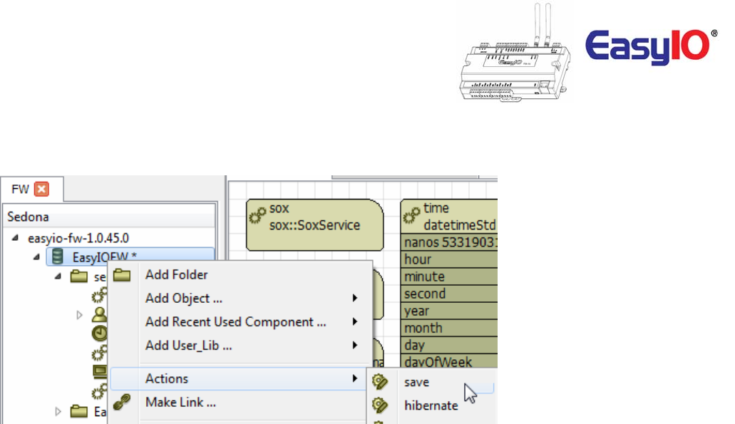
Step3
SavetheSedonaappsandcyclepower.
Step4
ReconnecttothecontrollerviaSedonaworkbenchusingthenewconfiguredIPaddress.
EasyIOFW‐14–UserReference
20
Restorefactorysettings
Thisfunctionisdonewithjustthebypressingthe“Service”buttonwhilethecontrollerisbootingup.
Arestoretofactorysettingswilldothefollowing;
1. RestoretheIPaddresstothedefaultwhichis192.168.10.14
2. CleartheSedonaapplicationintheSedonaVMbacktodefault(defaultappisanemptyapp)
3. AdefaultSedonaappsdefaultloginisadmin,<nopassword>.
Followthestepsbelowtorestoretofactorysettings.
Step1
MakesureyoubackuptheSedonaappsifyouhaveconnectiontotheEasyIOFW‐14.
Step2
Cyclepowerandwithin5secondspressandHOLDdowntheservicebuttonuntiltheErrorLEDstartsto
flash.
Thisprocesswilltakeapproximately10secondsbeforetheerrorLedstarttoblink.
Step3
OncetheRedLEDflashes,amomentarypressoftheservicebuttonwillrestorebacktheFW‐14controller
backtofactorydefaultstate.

EasyIOFW‐14–UserReference
21
TechnicalSupport
Fortechnicalissue,pleasecontact
Email:support@easyio.com