Eaton Electrical 350 Users Manual
350 to the manual 260fd08d-3c4c-4610-b500-16011c35ef6e
2015-02-06
: Eaton-Electrical Eaton-Electrical-350-Users-Manual-537245 eaton-electrical-350-users-manual-537245 eaton-electrical pdf
Open the PDF directly: View PDF ![]() .
.
Page Count: 45
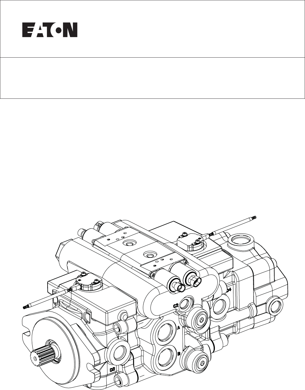
Dual Path Mobile Pumps
Parts and Repair Manual
350 Series

2EATON 350 Series Dual Path Mobile Pumps E-PUPI-TS006-E September 2007
Introduction ....................................................................................2
Exploded View ................................................................................3
Parts List ........................................................................................5
Model Code....................................................................................8
Rotating Kit Assembly ..................................................................10
Drive Shafts ..................................................................................13
Relief Valve Sub-Assembly............................................................14
Housing Identification ..................................................................14
Servo Piston Assembly ................................................................15
Index of Mechanical Servo Controllers,
Control Valve Sub-Assemblies......................................................16
Charge Pump Adapter Assumbly..................................................24
Assembly......................................................................................25
Required Tools ..........................................................................25
Swash Plate Sub-Assembly......................................................26
Mechanical Servo Control ........................................................27
Rotating Kit Asembly................................................................29
Servo Piston Assembly............................................................30
Dual Pump Housing Assembly ................................................31
Rear Pump Assembly ..............................................................32
Front Pump Assembly..............................................................35
Troubleshooting ..........................................................................39
Start-Up Procedure ......................................................................44
How To Order................................................................................45
Table of Contents
Introduction
This manual provides service
information for the Eaton
Model 350 Series Piston
Pumps. Step-by-step instructions
for the complete assembly
of the pump are given. For
dis-assembly, follow the reverse
of the assembly instructions.
These recommendations
should be followed to insure
successful repairs.
• Remove the pump from the
vehicle.
• Cleanliness is extremely
important.
• Clean the port areas thor-
oughly before disconnecting
the hydraulic lines.
• Plug the pump ports and
cover the open hydraulic
lines immediately after
they’re disconnected.
• Drain the oil and clean the
exterior of the pump before
making repairs.
• Wash all metal parts in
clean solvent.
• Use compressed air to dry
the parts. Do not wipe them
dry with paper towels or
cloth.
• The compressed air should
be filtered and moisture
free.
• Always use new seals when
reassembling hydraulic
pumps.
• Lubricate the new rubber
seals with a petroleum jelly
(Vaseline) before installation.
• Torque all bolts over gasketed
joints, then repeat torquing
sequence to make up for
gasket compression.
• Verifying the accuracy of
pump repairs on an authorized
test stand is essential.
3
EATON 350 Series Dual Path Mobile Pumps E-PUPI-TS006-E September 2007
77
89
60
60
61
61
59
70 71 72
1
43, 44, 45, 46
43, 44, 45, 46
75
74
53, 88
53, 88
87 90
90
51, 52 50
47
67
2, 3, 4, 5, 6, 73
13
39
54
48, 49
30
6, 7, 8
7
15
89
16 31 20, 33
22, 35
42
76
59
47
17
41
27
55
57, 58
56
25
24
42
10
54
26
30
9, 10, 11, 12
29
21
20, 33
14
17
15
16
18
28
22, 35
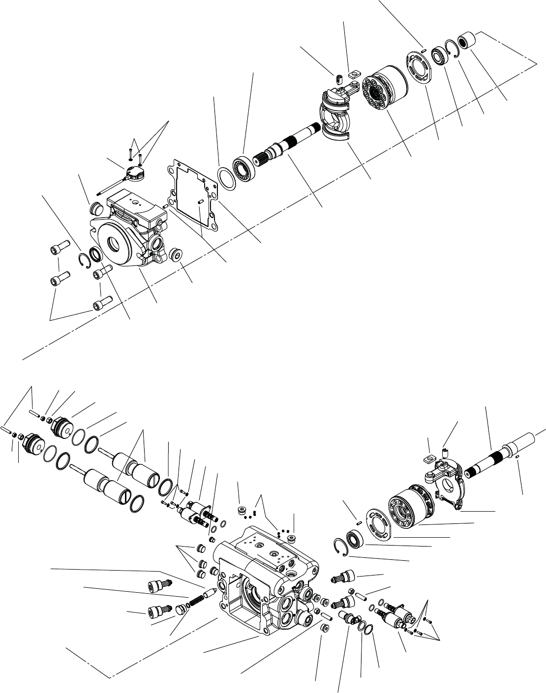
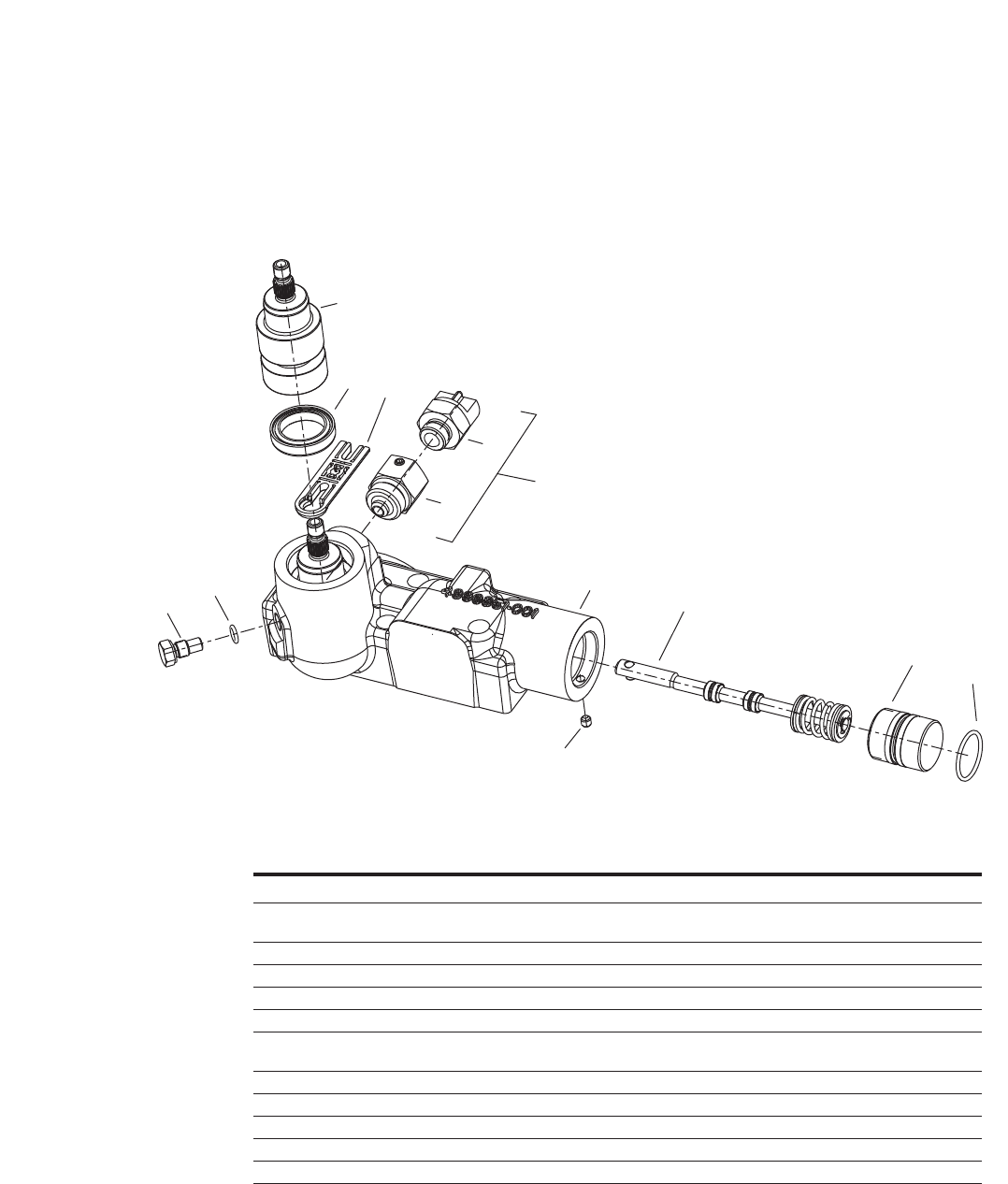
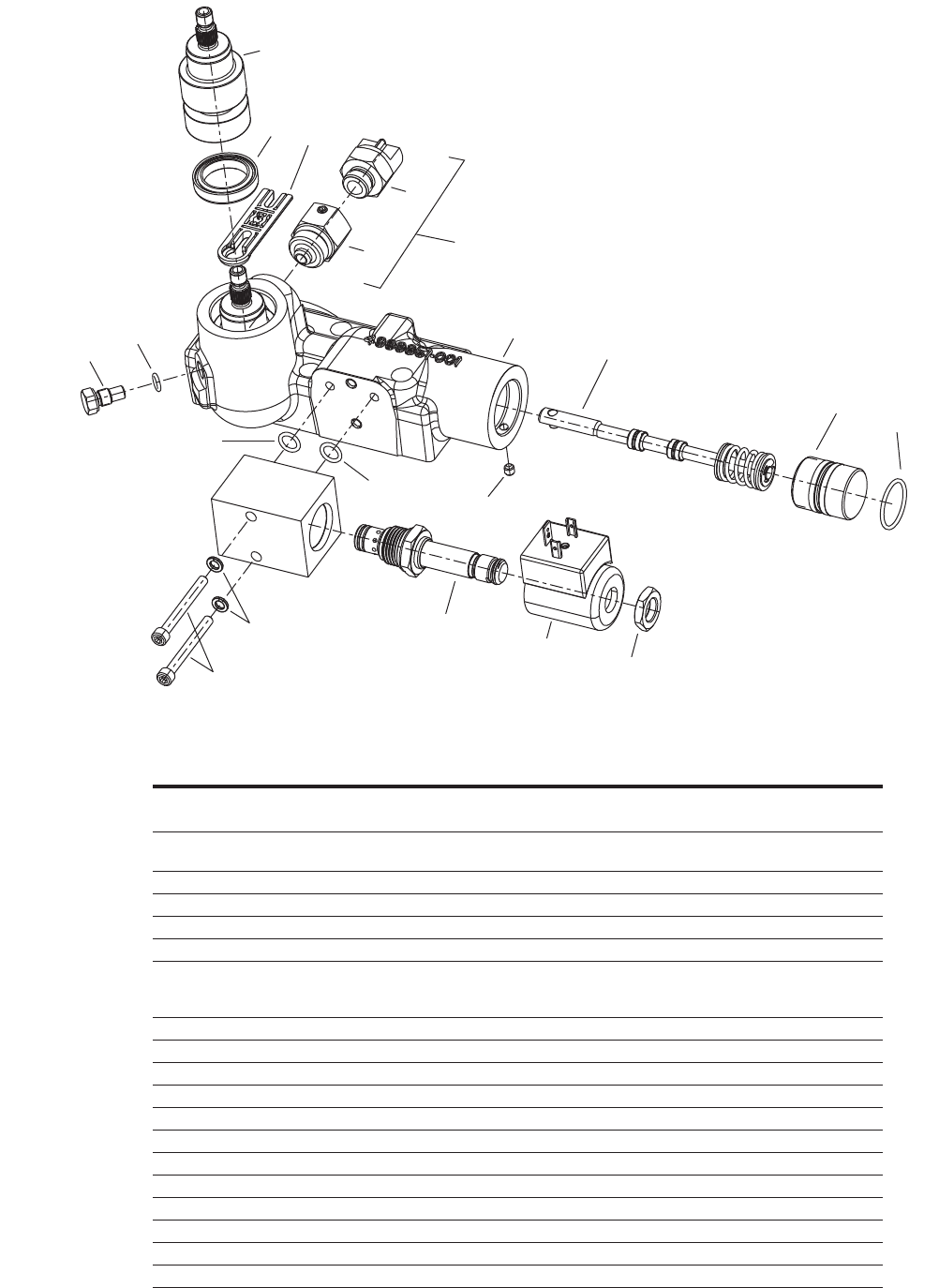
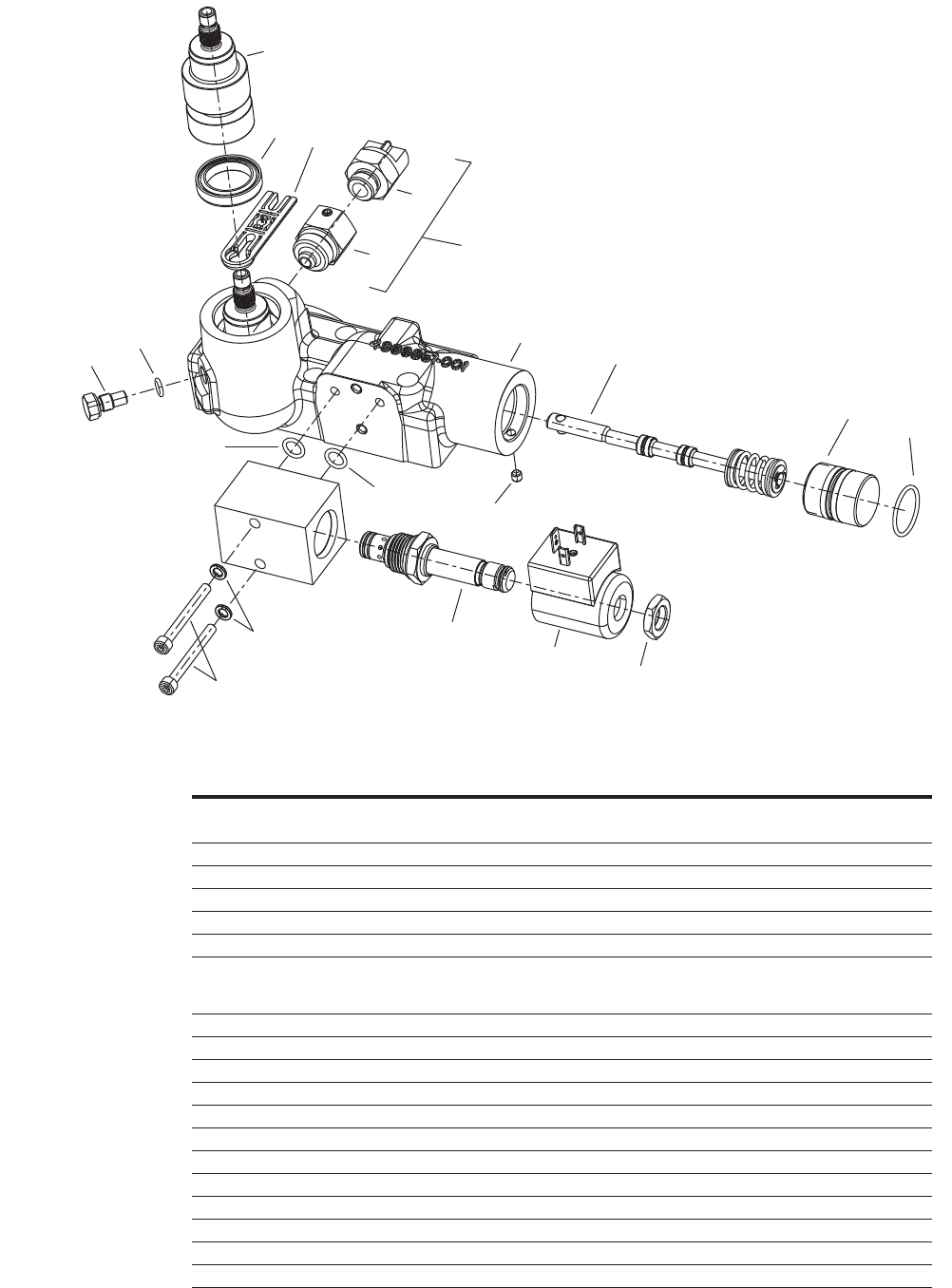
Parts -
Exploded View
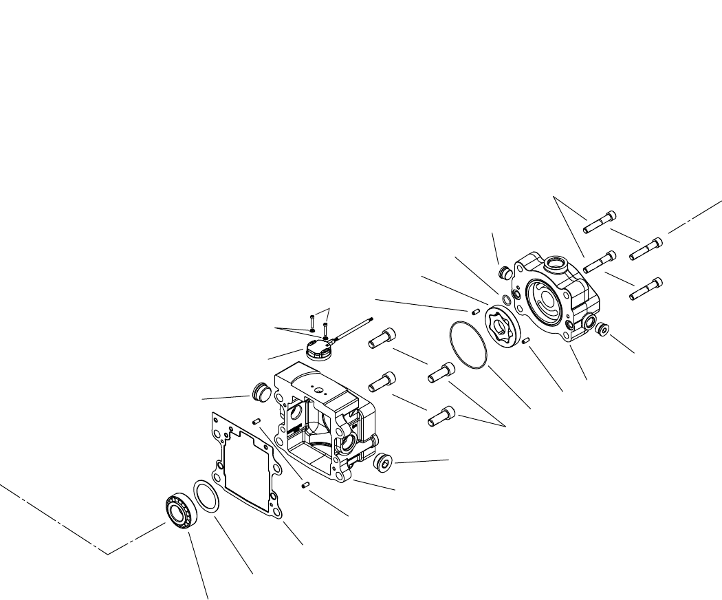
Parts -
Exploded View
4EATON 350 Series Dual Path Mobile Pumps E-PUPI-TS006-E September 2007
37
12
55
57, 58
56 79
78 79 83
81
84
85, 86
85, 86
38
34
29
40
11
41
82
Note: Investigating having this
page fold out from page 3 so that
Parts drawings are together

5
EATON 350 Series Dual Path Mobile Pumps E-PUPI-TS006-E September 2007
Parts List
1 1 5989802-XXX* Housing with Control Assembly HA, MA, MB, MC, MD, ME, MF and Main Ports A & B
1 1 5989803-XXX* Housing with Control Assembly SA, SB, SC and Main Ports A & B
1 1 5989804-XXX* Housing with Control Assembly HA, MA, MB, MC, MD, ME, MF and Main Port C
1 1 5989805-XXX* Housing with Control Assembly SA, SB, SC and Main Port C
2-5 7 16103-308 Plug Assembly
6-8 3 16103-304 Plug Assembly
9-12 4 16103-316 Plug Assembly
13 8 472187 Plug Expander Type
14 1 5986543-001 Coupler
15 2 16077-033 Retaining Ring
16 2 5988198-001 Bearing, Taper
17 2 16026-610 Pin, Roll
18 1 5990287-001 Valve Plate, LH (2.50) - 41cc
1 5990288-001 Valve Plate, RH (2.50) - 41cc
1 5990289-001 Valve Plate, LH (3.00) - 49cc
1 5990290-001 Valve Plate, RH (3.00) - 49cc
1 5987231-001 Valve Plate, LH (3.80) - 62cc
1 5986812-001 Valve Plate, RH (3.80) - 62cc
20 1 4999504-001 Rotating Kit LH (2.50) - 41cc
1 5991532-001 Rotating Kit RH (2.50) - 41cc
1 4999502-001 Rotating Kit LH (3.00) - 49cc
1 5991530-001 Rotating Kit RH (3.00) - 49cc
1 4999506-001 Rotating Kit LH (3.80) - 62cc
1 5991720-001 Rotating Kit RH (3.80) - 62cc
21 1 5989712-001 Gasket, Flange
22 1 5990298-001 Swashplate Sub-assembly
24 1 5988197-001 Bearing, Taper
25 A/R 114746-XXX Shim
26 1 4993012-003 Shaft Seal A, High Pressure Polyacryalate
1 16253-020 Shaft Seal B, High Pressure Nitrile
27 1 16077-028 Ring, Retaining Internal
28 1 5987541-001 Drive Shaft - Front 4-Bolt C (14T)
1 5989544-001 Drive Shaft - Front 2-Bolt C (14T)
1 5991587-001 Drive Shaft - Front 2-Bolt B (Dia. 1.00 taper)
1 5992243-001 Drive Shaft - Front 2-Bolt B (15T)
1 5992425-001 Drive Shaft - Front 2-Bolt C (19T)
1 5993096-001 Drive Shaft - Front 2-Bolt B (14T)
29 4 16026-810 Pin, Roll
30 1 5990395-XXX* Flange, Front 4-Bolt C (Manual)
1 5990396-XXX* Flange, Front 4-Bolt C (Solenoid)
1 5990398-XXX* Flange, Front 2-Bolt C (Manual)
1 5990399-XXX* Flange, Front 2-Bolt C (Solenoid)
1 5990095-XXX* Flange, Front 2-Bolt B (Manual)
1 5990096-XXX* Flange, Front 2-Bolt B (Solenoid)
1 5993095-XXX* Flange, Front 2-Bolt B (HRC)
1 5991841-XXX* Flange, Front 2-Bolt C (HRC)
31 1 5990287-001 Valve Plate LH (2.50) - 41cc
1 5990288-001 Valve Plate RH (2.50) - 41cc
1 5990289-001 Valve Plate LH (3.00) - 49cc
1 5990290-001 Valve Plate RH (3.00) - 49cc
1 5987231-001 Valve Plate LH (3.80) - 62cc
1 5986812-001 Valve Plate RH (3.80) - 62cc
ITEM # QTY PART # DESCRIPTION
* Reference individual assembly parts lists for further detail.
A/R - as required

6EATON 350 Series Dual Path Mobile Pumps E-PUPI-TS006-E September 2007
Parts List
ITEM # QTY PART # DESCRIPTION
33 1 4999504-001 Rotating Kit LH (2.50) - 41cc
1 5991532-001 Rotating Kit RH (2.50) - 41cc
1 4999502-001 Rotating Kit LH (3.00) - 49cc
1 5991530-001 Rotating Kit RH (3.00) - 49cc
1 4999506-001 Rotating Kit LH (3.80) - 62cc
1 5991720-001 Rotating Kit RH (3.80) - 62cc
34 1 5989712-001 Gasket, Flange
35 1 5990298-001 Swashplate Sub-Assembly
37 1 5988197-001 Bearing, Taper
38 A/R 114746-001 Shim
39 1 5987349-001 Drive Shaft - Rear (15T w/ Charge Pumps 1, 2)
1 5987349-002 Drive Shaft - Rear (15T w/ Charge Pumps 3, 4)
1 5989545-001 Drive Shaft - Rear (15T w/o Charge Pump)
1 5991280-001 Drive Shaft - Rear (13T w/ Charge Pumps 1, 2)
1 5991280-002 Drive Shaft - Rear (13T w/ Charge Pumps 3, 4)
1 5991466-001 Drive Shaft - Rear (13T w/o Charge Pump)
1 5992244-001 Drive Shaft - Rear (11T w/o Charge Pump)
40 1 5990401-XXX* Flange, Rear 2-Bolt B (Manual)
1 5990402-XXX* Flange, Rear 2-Bolt B (Solenoid)
1 5991202-XXX* Flange, Rear Charge Pump (Manual)
1 5991203-XXX* Flange, Rear Charge Pump (Solenoid)
1 5992240-XXX* Flange, Rear 2-Bolt A (Manual)
1 5992241-XXX* Flange, Rear 2-Bolt A (Solenoid)
1 5991842-XXX* Flange, Rear Charge Pump (HRC)
1 5992242-XXX* Flange, Rear 2-Bolt A (HRC)
1 5996777-XXX* Flange, Rear 2-Bolt B (HRC)
41 8 114978-045 Screw, Cap, Hex Socket Head
42 2 4999637-001 Follower, Servo Piston
43-46 1 110700-XXX Relief Valve Sub-assembly (reference page 13 for further detail)
47 4 5987241-001 Piston Ring
48 1 5989959-001 Servo Piston Sub-assembly (Used with Controls: MA, MB, MC, MD, MF, SA, SB, SC)
1 5989958-001 Servo Piston Sub-assembly (Used with Control: HA)
49 1 5989959-001 Servo Piston Sub-assembly (Used with Controls: MA, MB, MC, MD, MF, SA, SB, SC)
1 5989958-001 Servo Piston Sub-assembly (Used with Control: HA)
50 2 16015-34 O-Ring
51 1 5989898-001 Servo Cap Plug
1 5991129-001 Servo Cap Plug
52 1 5989898-001 Servo Cap Plug
1 5991129-001 Servo Cap Plug
53 2 5996839-001 Nut, Sealing
54 2 5990203-001 Magnet Carrier
55 2 5990202-001 Feedback Sensor (SB) - Control
2 5990202-002 Feedback Sensor (SA) - Control
56 4 5996053-002 Screw
57 4 4994180-016 Washer
58 4 16133-208 O-Ring
59 4 5991234-001 Proportional Flow Regulator (SA Control)
60 6 95897-008 Washer
61 6 16147-204 Screw, Cap, Hex Socket Head
62 2 4999960-001 Feedback Control Link
63 2 5987239-001 Gasket
* Reference individual assembly parts lists for further detail.
A/R - as required

7
EATON 350 Series Dual Path Mobile Pumps E-PUPI-TS006-E September 2007
ITEM # QTY PART # DESCRIPTION
64 1 5986768-XXX* Control Valve Sub-assembly
65 1 5986768-XXX* Control Valve Sub-assembly
66 12 114975-025 Screw, Cap, Hex Socket Head
67 2 95729-000 Control Lever
68 2 16045-205 Lockwasher
69 2 16021-5 Nut
70 1 4995422-001 Magnetic Speed Sensor
71 1 16048-077 Washer
72 1 16160-125 Retaining Ring, Inverted Internal
73 1 16103-308 Plug Sub-assembly
74 1 4998532-001 Poppet
75 1 4998533-001 Spring, Compression
76 A/R 16048-597 Shim
77 1 72400-659 Plug Sub-assembly
78 1 16015-055 O-Ring
79 2 16026-810 Pin, Roll
80 1 101305-000 Charge Pump Drive Pin
81 1 5987263-XXX* Gerotor Sub-assembly
82 2 16003-013 O-Ring
83 1 5991128-XXX* Charge Pump Adapter (RH Rotation)
1 5991230-XXX* Charge Pump Adapter (LH Rotation)
84 4 114977-070 Screw, Cap, Hex Socket Head
85, 86 1 16103-310 Plug Sub-assembly
87 2 16139-644 Set Screw
88 2 5996839-001 Nut, Sealing
89 2 16139-444 Set Screw
90 2 5996838-001 Nut, Sealing
91 1 5991133-001 Actuator, Bypass Valve - Main Ports A, B, D, E
92 2 5991131-001 Actuator, Bypass Valve - Main Ports C, F
Parts List
* Reference individual assembly parts lists for further detail.
A/R - as required

8EATON 350 Series Dual Path Mobile Pumps E-PUPI-TS006-E September 2007
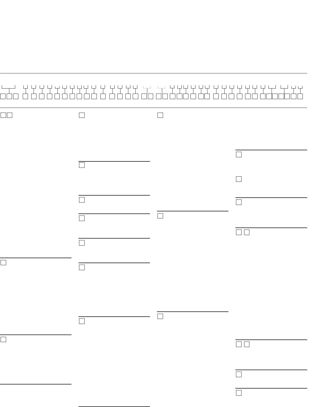
Model Code
Code Title
AED – Dual Servo Controlled
Variable Displacement Axial
Piston Pump
Displacement & Rotating
Kit- Front
1– 41.0 cm3/r [2.50 in3/r]
2– 49.2 cm3/r [3.00 in3/r]
3– 62.3 cm3/r [3.80 in3/r]
4– 35.0 cm3/r [2.10in3/r]
Destroked from -
41.0 cm3/r [2.50 in3/r]
5– 45.0 cm3/r [2.75 in3/r]
Destroked FROM -
49.2 cm3/r [3.00 in3/r]
6– 54.0 cm3/r [3.30 in3/r]
Destroked FROM -
62.3 cm3/r [3.80 in3/r]
Input Shaft Rotation
L– Left hand rotation (CCW)
R– Right hand rotation (CW)
Front Mounting
A– 2 Bolt C (SAE J744-127-2)
B– 4 Bolt C (SAE J744-127-4)
C– 2 Bolt B (SAE J744-101-2)
Input Shaft
A– Taper shaft 1.0 dia 1.5 taper
B– 14 Tooth 12/24 Pitch Spline
Shaft
C–15 Tooth 16/32 Pitch Spline
Shaft
D–19 Tooth 16/32 Pitch Spline
Shaft
Valve Plate - Front
A– Type 1- Standard
Relief Setting for Front
Main Port A - Front
0– None, no relief valve or
check valve
A– Check valve only
J– 207 bar [3000 lbf/in2]
K– 224 bar [3250 lbf/in2]
L– 241 bar [3500 lbf/in2]
M– 259 bar [3750 lbf/in2]
N– 280 bar [4000 lbf/in2]
R– 310 bar [4500 lbf/in2]
T– 345 bar [5000 lbf/in2]
U– 362 bar [5250 lbf/in2]
V– 380 bar [5500 lbf/in2]
Relief Setting for Front
Main Port B - Front
0– None, no relief valve or
check valve
A– Check valve only
J– 207 bar [3000 lbf/in2]
K– 224 bar [3250 lbf/in2]
L– 241 bar [3500 lbf/in2]
M– 259 bar [3750 lbf/in2]
N– 280 bar [4000 lbf/in2]
R– 310 bar [4500 lbf/in2]
T– 345 bar [5000 lbf/in2]
U– 362 bar [5250 lbf/in2]
V– 380 bar [5500 lbf/in2]
Displacement & Rotating
Kit - Rear
1– 41.0 cm3/r [2.50 in3/r]
2– 49.2 cm3/r [3.00 in3/r]
3– 62.3 cm3/r [3.80 in3/r]
4– 35.0 cm3/r [2.10in3/r]
Destroked from -
41.0 cm3/r [2.50 in3/r]
5– 45.0 cm3/r [2.75 in3/r]
Destroked FROM -
49.2 cm3/r [3.00 in3/r]
6– 54.0 cm3/r [3.30 in3/r]
Destroked FROM -
62.3 cm3/r [3.80 in3/r]
Valve Plate - Rear
A– Type 1- Standard
Relief Setting For Front
Main Port A - Rear
Ref Position 9 for options
Relief Setting For Front
Main Port B - Rear
Ref Position 10 for options
Charge Pump
0– No Charge Pump
1– 13.9 cm3/r [.85in3/r],
1.3125-12 UN-2B SAE O-Ring
Suction Inlet Port (S)
2– 17.4 cm3/r [1.06 in3/r],
1.3125-12 UN-2B SAE O-Ring
Suction Inlet Port (S)
3– 21.0 cm3/r [1.28 in3/r],
1.3125-12 UN-2B SAE O-Ring
Suction Inlet Port (S)
4 – 23.1 cm3/r [1.41 in3/r],
1.3125-12 UN-2B SAE O-Ring
Port for Suction Inlet (S)
Charge Relief Setting
0– No Charge Relief Setting
1– 17.2 - 20.7 bar [250-300 lbf/in2]
Relieved to Case
2– 20.7 - 24.1 bar [300-350 lbf/in2]
Relieved to Case
3– 24.1 - 27.6 bar [350-400 lbf/in2]
Relieved to Case
4– 27.6 - 31 bar [400-450 lbf/in2]
Relieved to Case
5– 13.8 - 17.2 bar [400-450 lbf/in2]
Relieved to Case
Charge Port Location
0– None
1– Inlet Right Side C2 (Only
with Main Ports opposite side)
2– Inlet Left Side C1
3– Inlet Bottom C3 (Only with
Main Ports Same Side, No
Bypass Valve)
Auxiliary (Rear) Mount &
Output Shaft
A– 2 Bolt B (SAE J744-101-2)
Accepts 13T, 16/32 Pitch
Spline
B– 2 Bolt B (SAE J744-101-2)
Accepts 15T, 16/32 Pitch
Spline
C– 2 Bolt A (SAE J744- 82-2)
Accepts 11T, 16/32 Pitch
Spline
D– 2 Bolt A (SAE J744-82-2)
Accepts 9T, 16/32 Pitch Spline
Control Assembly -
Front
SA – Solenoid Control -
12 Volt With Non-Contact
Feedback Sensor with Metri-
Pak Electrical Connectors
SB – Solenoid Control -
12 Volt
SC – Solenoid Control -
12 Volt
HA – Hydraulic Remote - Non
Feedback, 5-15 bar [72-217
lbf/in2] Pilot Pressure
MA – Manual Control,Wide
Band Neutral
MB – Manual Control,
Standard
MC – Manual Control, High Gain
MD – Manual Control,
Wide Band Neutral, Neutral
Lockout switch
ME – Manual Control, Standard,
Neutral Lockout switch
MF – Manual Control, High
Gain, Neutral Lockout switch
19 20
14 18
16
17
15
13
12
932
4
11
10
8
7
6
5
1
AED * * * * A * * * * * * * * * * ** ** * * * 0 * * * * * * * * * 00 ** 0 A
1 2 3 4 5 6 7 8 9 10 11 12 13 14 15 16 17 18 19 20 21 22 23 24 25 26 27 28 29 30 31 32 33 34 35 38 39 40 41 42 43
9
EATON 350 Series Dual Path Mobile Pumps E-PUPI-TS006-E September 2007
Control Assembly -
Rear
SA – Solenoid Control -
12 Volt with Non-Contact
Feedback Sensor
SB – Solenoid Control -
12 Volt with Redundant
Non-Contact Feedback Sensor
SC – Solenoid Control -
12 Volt
HA – Hydraulic Remote -
Non Feedback, 5-15 bar
[72-217 lbf/in2] Pilot Pressure
MA – Manual Control,
Wide Band Neutral
MB – Manual Control, Standard
MC – Manual Control, High Gain
MD – Manual Control,
Wide Band Neutral, Neutral
Lockout switch
ME – Manual Control, Standard,
Neutral Lockout switch
MF – Manual Control, High
Gain, Neutral Lockout Switch
Destroke Valve - Front
0– Not required
1– Destroke With 12 VDC
Coil & Weather Pack
Connector
2– Destroke With 24 VDC
Coil & Weather Pack
Connector
3– 12 VDC Coil & DIN 43650-
A Connector
4– Destroke with 24 VDC Coil
& DIN 43650-A Connector
Control Supply
Orifice (p) - Front
0– No control, supply orifice
B– Diameter 0.71 [.028]
C– Diameter 0.91 [.036]
D– Diameter 1.12 [.044]
E– Diameter 1.32 [.052]
Control Servo Orifice
(s1 and s2) - Front
0– No control, servo orifice
B– Diameter 0.71 [.028]
C– Diameter 0.91 [.036]
D– Diameter 1.12 [.044]
E– Diameter 1.32 [.052]
Special Control Options -
Front
0– No Special Control
Options
1– Manual Control Lever
Destroke Valve - Rear
Ref Position 23 for options
Control Supply
Orifice (p) - Rear
Ref Position 24 for options
Control Servo Orifice
(s1 and s2) - Rear
Ref Position 25 for options
Special Control Options -
Rear
0– No Special Control
Options
1– Manual Control Lever
2– Control Pressure EPRV
Valve 12 VDC, Deutsch, -4
SAE O-Ring Port
Main Ports (A and B)
A– 4X 1.3125-12 UN-2B SAE
O-Ring Ports; Same Side,
Right
B– 4X 1.3125-12 UN-2B SAE
O-Ring Ports; Same Side, Left
C– 4X 1.3125-12 UN-2B SAE
O-Ring Ports; Opposite Side
D– 4X -16 STC TYPE II+
Direct Port; Same Side, Right
E– 4X -16 STC TYPE II+
Direct Port; Same Side, Left
F– 4X -16 STC TYPE II+
Direct Port; Opposite Side
Drain Port Size and
Location - Front
0– No Drain Port
1– 1.0625 -12 UN-2B SAE
O-Ring Port - Left (D1)
2– 1.0625 -12 UN-2B SAE
O-Ring Port - Right (D2)
3– 1.0625 -12 UN-2B SAE
O-Ring Port - Left (D1) and
Right (D2)
4– 1.0625 -12 UN-2B SAE
O-Ring Port - Left (D1) and
Right (D2), Left Side Plugged
5– 1.0625 -12 UN-2B SAE
O-Ring Port - Left (D1) and
Right (D2), Right Side Plugged
Drain Port Size and
Location - Rear
0– No Drain Port
1– 1.0625 -12 UN-2B SAE
O-Ring Port - Left (D3)
2– 1.0625 -12 UN-2B SAE
O-Ring Port - Right (D4)
3– 1.0625 -12 UN-2B SAE
O-Ring Port - Left (D3) and
Right (D4)
4– 1.0625 -12 UN-2B SAE
O-Ring Port - Left (D3) and
Right (D4), Left Side Plugged
5– 1.0625 -12 UN-2B SAE
O-Ring Port - Left (D3) and
Right (D4), Right Side Plugged
Auxiliary Port
0– No Auxiliary Port
A– .750-16 UNF-2B SAE
O-Ring Port - Left (C1) and
Right (C2), Left Side Plugged
B– .750-16 UNF-2B SAE
O-Ring Port - Left (C1) and
Right (C2), Right Side Plugged
C– .750-16 UNF-2B SAE
O-Ring Port - Left (C1) and
Right (C2)
D– .750-16 UNF-2B SAE
O-Ring Port - Left (C1) and
Right (C2), Left Side Plugged,
Remote Filter, Return from
Filter to Charge Port Required
(#34 continues next column)
(continued from previous column)
E– .750-16 UNF-2B SAE
O-Ring Port - Left (C1) and
Right (C2), Right Side Plugged,
Remote Filter, Return from
Filter to Charge Port Required
Bypass Valve
0– No Bypass Valve
A– With Bypass Valve
Sensor Options
0– No Sensor
A– Magnetic Speed Sensor
Shaft Seal
A– Polyacrylate
B– Nitrile
C– Viton
Special Features
00 – No Special Features
AA – Diagnostic Ports - Front
Pump 2X .3125-24 SAE O-
Ring Ports (s1 & s2), Rear
Pump
2X .3125-24 SAE O-Ring Ports
(s1 & s2)
AB – Externally Adjustable
Displacement Limiters
AC – Diagnostic Ports - Front
Pump 2X .3125-24 SAE O-
Ring Ports (s1 & s2), Rear
Pump
2X .3125-24 SAE O-Ring Ports
(s1 & s2), Externally
Adjustable Displacement
Limiters
Paint
0A – Primer Red
0B – Primer Black
CD – Primer Blue
Identification
A– Standard
Design Code
A–
21 22
23
36
24
43
42
4140
3938
37
35
34
33
32
31
30
29
28
27
26
25
AED * * * * A * * * * * * * * * * ** ** * * * 0 * * * * * * * * * 00 ** 0 A
1 2 3 4 5 6 7 8 9 10 11 12 13 14 15 16 17 18 19 20 21 22 23 24 25 26 27 28 29 30 31 32 33 34 35 38 39 40 41 42 43
Model Code
10 EATON 350 Series Dual Path Mobile Pumps E-PUPI-TS006-E September 2007
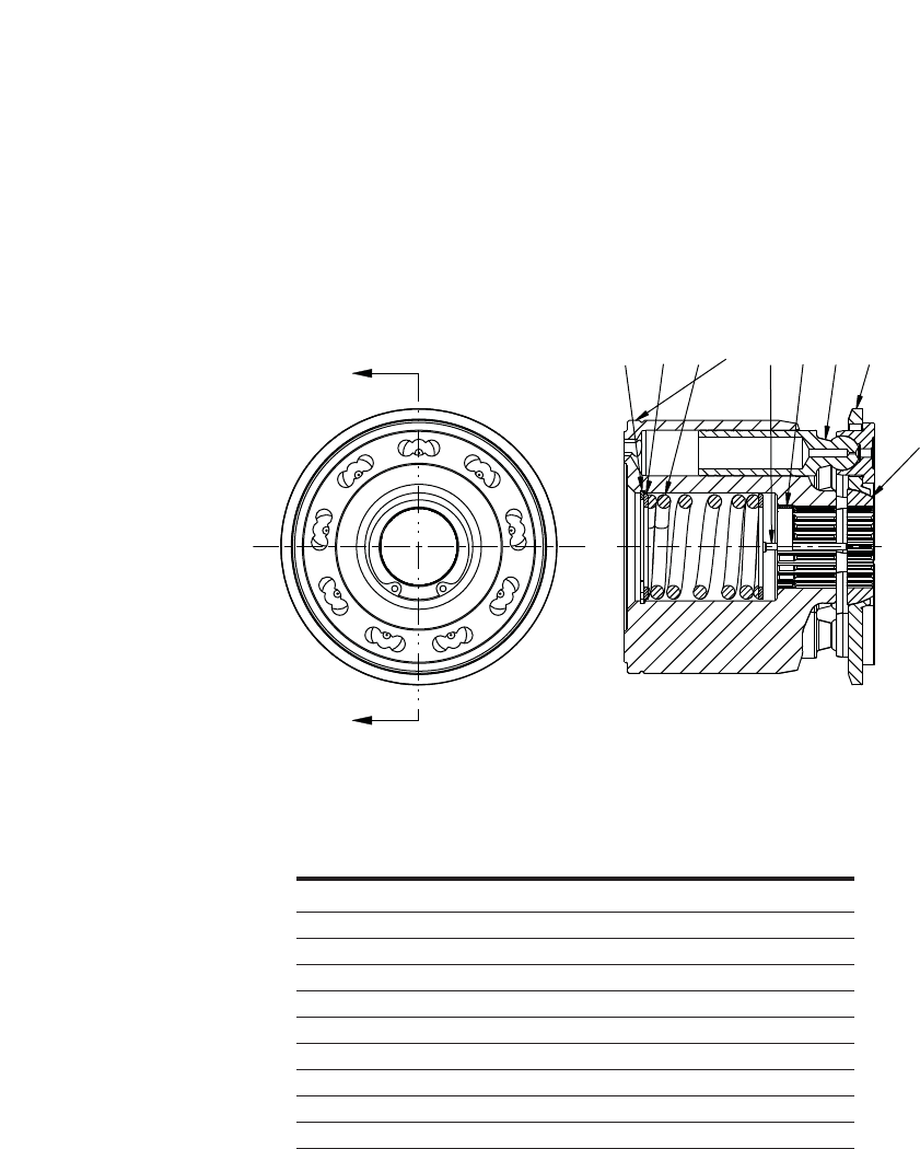
Item 20, 33 -
Rotating Kit
Assembly
Displacement 2.5 cid (41 cc)
A
A
2351489
6
7
Section A-A
4999504-001 1 Rotating Kit Sub-Assembly
1 NSS 1 Cylinder Barrel
2 NSS 1 Internal Retaining Ring
3 NSS 2 Washer
4 NSS 3 Loading Pin
5 NSS 1 Spring
6 NSS 1 Pivot
7 NSS 1 Shoe Retainer
8 NSS 1 Load Pin Keeper
9 NSS 9 Piston Sub-Assembly
* 5991532-001 Rotating Kit S/A set up for Speed Sensor.
NSS - Not Sold Separately
REF PART NO. QTY. DESCRIPTION
Item 20, 33
Rotating Kit Assembly
11
EATON 350 Series Dual Path Mobile Pumps E-PUPI-TS006-E September 2007
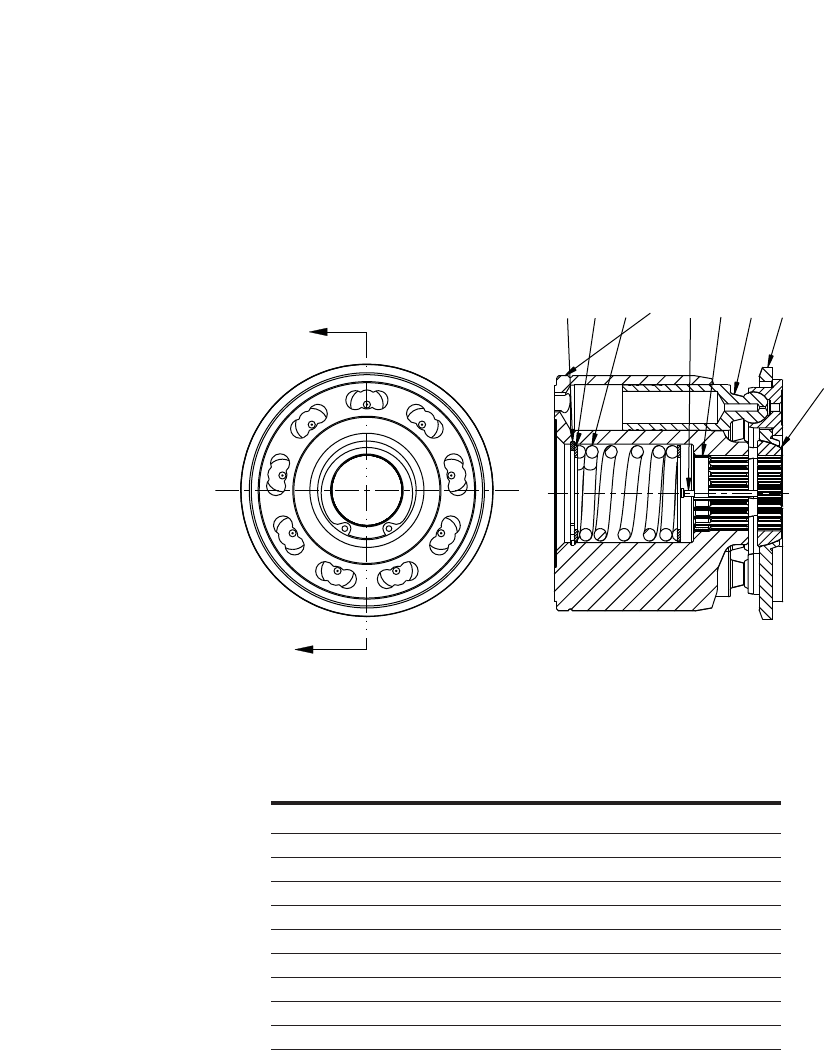
Item 20, 33 -
Rotating Kit
Assembly
Displacement 3.0 cid (49 cc)
A
A
4999502-001 1 Rotating Kit Assembly
1 NSS 1 Cylinder Barrel
2 NSS 1 Internal Retaining Ring
3 NSS 2 Washer
4 NSS 3 Loading Pin
5 NSS 1 Spring
6 NSS 1 Pivot
7 NSS 1 Shoe Retainer
8 NSS 1 Load Pin Keeper
9 NSS 9 Piston Sub-Assembly
* 5991530-001 Rotating Kit S/A set up for Speed Sensor.
NSS - Not Sold Separately
REF PART NO. QTY. DESCRIPTION
Item 20, 33
Rotating Kit Assembly
Section A-A
2351489
6
7
12 EATON 350 Series Dual Path Mobile Pumps E-PUPI-TS006-E September 2007
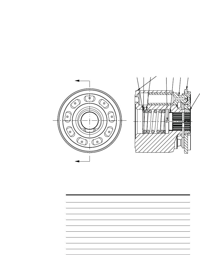
Item 20, 33 -
Rotating Kit
Assembly
Displacement 3.8 cid (62 cc)
A
A
Section A-A
23514 89
6
7
4999506-001 1 Rotating Kit Sub-Assembly
1 NSS 1 Cylinder Barrel
2 NSS 1 Internal Retaining Ring
3 NSS 2 Washer
4 NSS 3 Loading Pin
5 NSS 1 Spring
6 NSS 1 Pivot
7 NSS 1 Shoe Retainer
8 NSS 1 Load Pin Keeper
9 NSS 9 Piston Sub-Assembly
* 5991720-001 Rotating Kit S/A set up for Speed Sensor.
NSS - Not Sold Separately
REF PART NO. QTY. DESCRIPTION
Item 20, 33
Rotating Kit Assembly
13
EATON 350 Series Dual Path Mobile Pumps E-PUPI-TS006-E September 2007
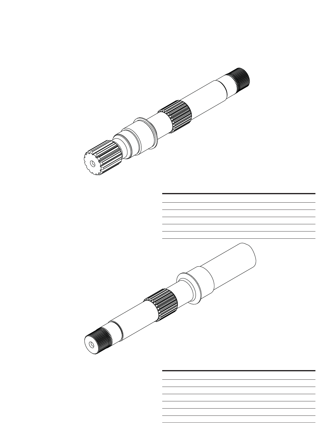
Item 28, 39 -
Drive Shafts
5987541-001 Drive Shaft - Front 4-Bolt C (14T)
5989544-001 Drive Shaft - Front 2-Bolt C (14T)
5991587-001 Drive Shaft - Front 2-Bolt B (Dia 1.00 taper)
5992243-001 Drive Shaft - Front 2-Bolt B (15T)
5992425-001 Drive Shaft - Front 2-Bolt C (19T)
5993096-001 Drive Shaft - Front 2-Bolt B (14T)
PART NO. DESCRIPTION
Item 28
Drive Shaft Front
5987349-001 Drive Shaft - Rear (15T w/Charge Pump)
5987349-002 Drive Shaft - Rear (15T w/Charge Pump)
5989545-001 Drive Shaft - Rear (15T w/o Charge Pump)
5991280-001 Drive Shaft - Rear (13T w/Charge Pump)
5991280-002 Drive Shaft - Rear (13T w/Charge Pump)
5991466-001 Drive Shaft - Rear (13T w/o Charge Pump)
5992244-001 Drive Shaft - Rear (11T w/o Charge Pump)
PART NO. DESCRIPTION
Item 39
Drive Shaft Rear
14 EATON 350 Series Dual Path Mobile Pumps E-PUPI-TS006-E September 2007
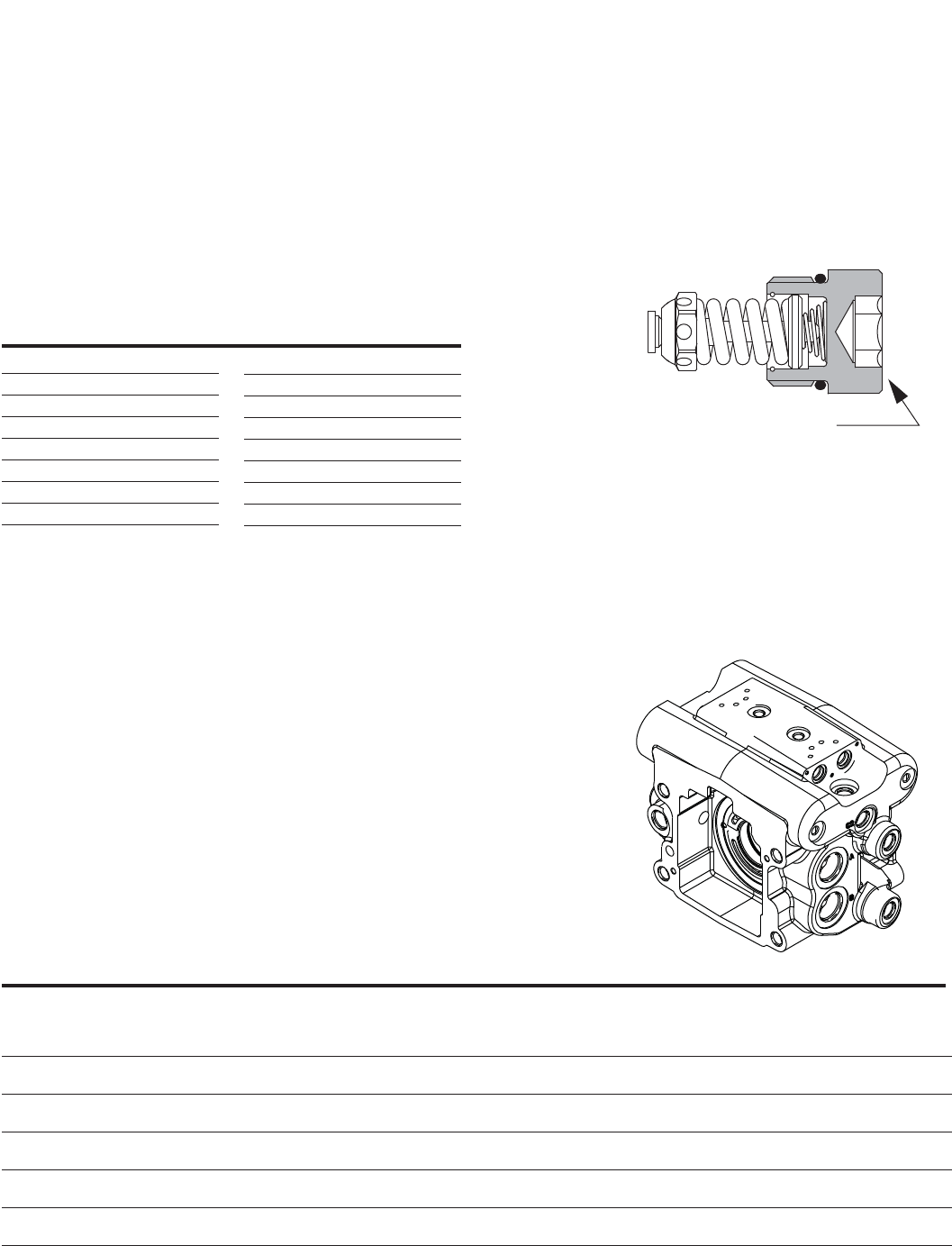
Item 43, 44, 45, 46 -
Relief Valve Sub-Assembly
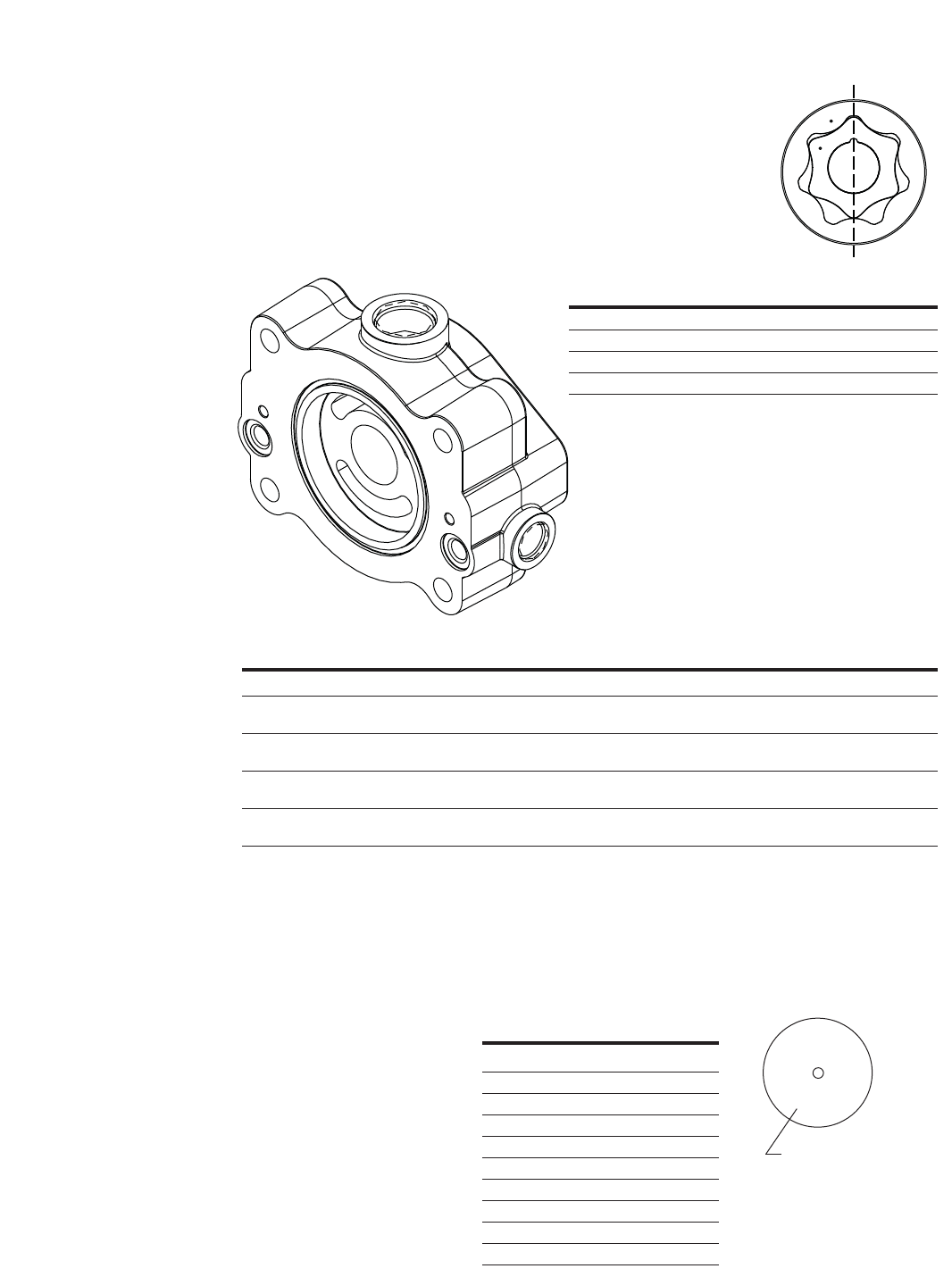
Item 1 -
Housing
Identification
Dash Number Stamped
here for Valve Pressure
Setting Identification
Example: 500 x 10 = [5000
PSI] 345 bar
Item 43, 44, 45, 46
Relief Valve Sub-Assembly
110700-150 103 [1500]
110700-175 121 [1750]
110700-200 138 [2000]
110700-225 155 [2250]
110700-250 172 [2500]
110700-275 190 [2750]
110700-300 207 [3000]
110700-325 224 [3250]
110700-350 241 [3500]
110700-375 259 [3750]
110700-400 276 [4000]
110700-425 293 [4250]
110700-450 310 [4500]
110700-475 328 [4750]
110700-500 345 [5000]
110700-550 380 [5500]
PART NO. BAR [PSI] PART NO. BAR [PSI]
Item 1
Housing Identification
REF PART NO. QTY. PUMP CONTROLS MAIN PORTS SPECIAL CONTROL OPTIONS
1 5989802-001 thru 1 HA,MA,MB,MC,MD,ME,MF A - 4X 1.3125-12 UN-2B SAE, Same Side, Right
5989802-016 B - 4X 1.3125-12 UN-2B SAE, Same Side, Left
1 5989802-017 thru 1 HA,MA,MB,MC,MD,ME,MF A - 4X 1.3125-12 UN-2B SAE, Same Side, Right Control Pressure EPRV Valve
5989802-032 B - 4X 1.3125-12 UN-2B SAE, Same Side, Left 12 VDC, Deutsch, -4 SAE O-Ring Port
1 5989803-001 thru 1 SA, SB, SC A - 4X 1.3125-12 UN-2B SAE, Same Side, Right
5989803-032 B - 4X 1.3125-12 UN-2B SAE, Same Side, Left
1 5989804-001 thru 1 HA,MA,MB,MC,MD,ME,MF C - 4X 1.3125-12 UN-2B SAE, Opposite Side
5989804-016
1 5989804-017 thru 1 HA,MA,MB,MC,MD,ME,MF C - 4X 1.3125-12 UN-2B SAE, Opposite Side Control Pressure EPRV Valve,
5989804-032 12 VDC, Deutsch, -4 SAE O-Ring Port
1 5989805-001 thru 1 SA, SB, SC C - 4X 1.3125-12 UN-2B SAE, Opposite Side
5989805-032
Part number range is impacted by the addition of special features, special control options, sensor options, and pump controls. Please reference the pump assembly parts list for the exact housing part number.
15
EATON 350 Series Dual Path Mobile Pumps E-PUPI-TS006-E September 2007
31526784
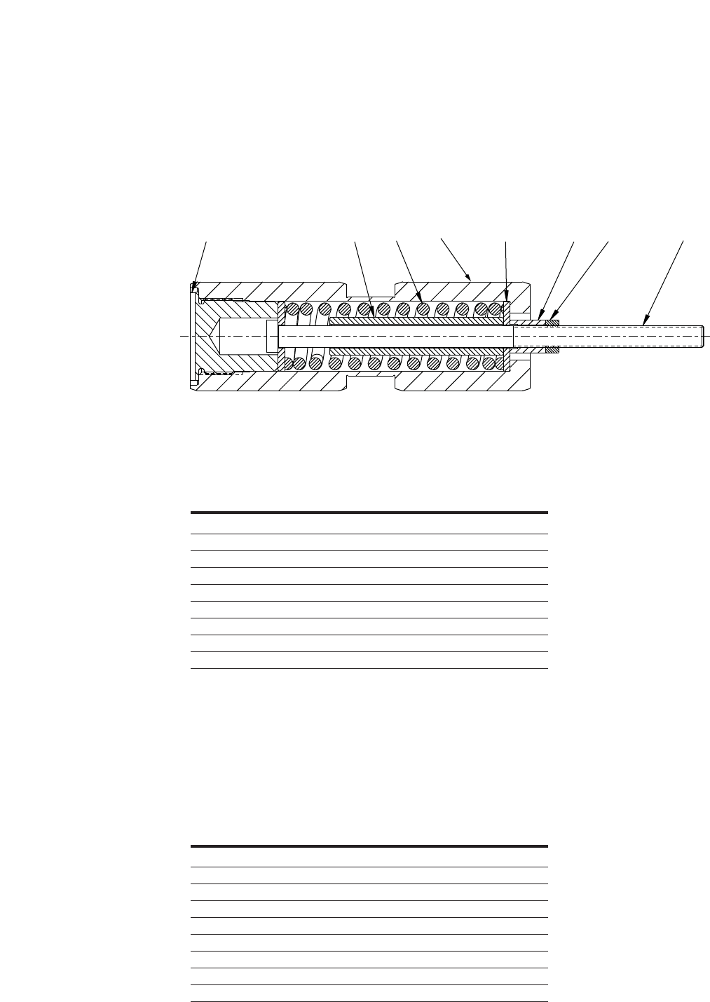
5989958-001 1 Servo Piston Sub-Assembly
1 NSS 1 Servo Piston
2 NSS 2 Spring Retainer
3 NSS 1 Servo Piston Plug
4 NSS 1 Servo Piston Bolt
5 NSS 2 Spring Stop
6 NSS 1 Spring
7 NSS 1 Hex Nut
8 NSS 1 Thin Hex Nut
NSS - Not Sold Separately
REF PART NO. QTY. DESCRIPTION
Item 48, 49
Servo Piston Assembly - Used with
MA, MB, MC, MD, ME, SA, SB, SC Controls
5989959-001 1 Servo Piston Sub-Assembly
1 NSS 1 Servo Piston
2 NSS 2 Spring Retainer
3 NSS 1 Servo Piston Plug
4 NSS 1 Servo Piston Bolt
5 NSS 1 Spring
6 NSS 1 Spring
7 NSS 1 Hex Nut
8 NSS 1 Thin Hex Nut
NSS - Not Sold Separately
REF PART NO. QTY. DESCRIPTION
Item 48, 49
Servo Piston Assembly - Used with
HA Control
Item 48, 49 -
Servo Piston
Assembly

16 EATON 350 Series Dual Path Mobile Pumps E-PUPI-TS006-E September 2007
Item 64, 65
Index of Mechanical
Servo Controllers –
Control Valve
Sub-Assembly
INDEX OF CONTROLLERS INDEX OF CONTROLLERS
Without Destroke Valve:
5986768-001 MA control: Manual Control,
Wide Band Neutral
5986768-002 MB control: Manual Control,
Standard
5986768-003 MC control: Manual Control,
HIGH GAIN
5986768-004 MD control: Manual Control, Wide Band Neutral,
Neutral Lockout Switch
5986768-005 ME control: Manual Control, Standard, Neutral
Lockout Switch
5986768-006 MF control: Manual Control, High Gain, Neutral
Lockout Switch
With Destroke Valve Option 1:
Destroke with 12 VDC Coil & Weather Pack Connector
5986768-007 MA control: Manual Control, Wide Band Neutral
5986768-008 MB control: Manual Control, Standard
5986768-009 MC control: Manual Control, High Gain
5986768-015 MD control: Manual Control, Wide Band Neutral,
Neutral Lockout Switch
5986768-016 ME control: Manual Control, Standard, Neutral
Lockout Switch
5986768-017 MF control: Manual Control, High Gain, Neutral
Lockout Switch
With Destroke Valve Option 2:
Destroke with 24 VDC Coil & Weather Pack Connector
5986768-010 MA control: Manual Control, Wide Band Neutral
5986768-011 MB control: Manual Control, Standard
5986768-012 MC control: Manual Control, High Gain
5986768-019 MD control: Manual Control, Wide Band Neutral,
Neutral Lockout Switch
5986768-020 ME control: Manual Control, Standard, Neutral
Lockout Switch
5986768-021 MF control: Manual Control, High Gain, Neutral
Lockout Switch
With Destroke Valve Option 3:
Destroke with 12 VDC Coil & DIN 43650-A Connector
5986768-013 MA control: Manual Control, Wide Band Neutral
5986768-014 MB control: Manual Control, Standard
5986768-015 MC control: Manual Control, High Gain
5986768-022 MD control: Manual Control, Wide Band Neutral,
Neutral Lockout Switch
5986768-023 ME control: Manual Control, Standard, Neutral
Lockout Switch
5986768-024 MF control: Manual Control, High Gain, Neutral
Lockout Switch
With Destroke Valve Option 4:
Destroke with 24 VDC Coil & DIN 43650-A Connector
5986768-025 MA control: Manual Control,
Wide Band Neutral
5986768-026 MB control: Manual Control, Standard
5986768-027 MC control: Manual Control, High Gain
5986768-028 MD control: Manual Control, Wide Band Neutral,
Neutral Lockout Switch
5986768-029 ME control: Manual Control, Standard, Neutral
Lockout Switch
5986768-030 MF control: Manual Control, High Gain,
Neutral Lockout Switch
17
EATON 350 Series Dual Path Mobile Pumps E-PUPI-TS006-E September 2007
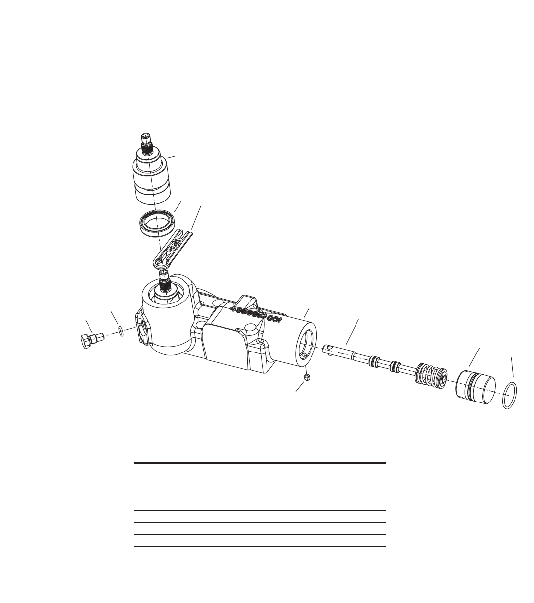
Item 64, 65
Mechanical Servo
Controllers –
(MA, MB)*
56
2
3
10
41 7
89
1 4999852-001 1 Housing, Control
2 5996108-001(MA) 1 Input Control Shaft Sub-Assembly
4999870-001(MB)
3 5987125-001 2 Plug
4 16133-2 3 O-Ring
5 72401-503 1 Seal, Shaft
6 5992233-001 1 Link, Feedback
7 4999884-001(MB) 1 Spool Sub-Assembly
4999884-002(MA)
8 72400-507 1 Plug
9 16015-8 1 O-Ring
10 102149-019 1 Set Screw
REF PART NO. QTY. DESCRIPTION
Item 64, 65
Control Valve Sub-Assembly
*reference Index of Mechincal Servo Controllers
on page 16.
18 EATON 350 Series Dual Path Mobile Pumps E-PUPI-TS006-E September 2007
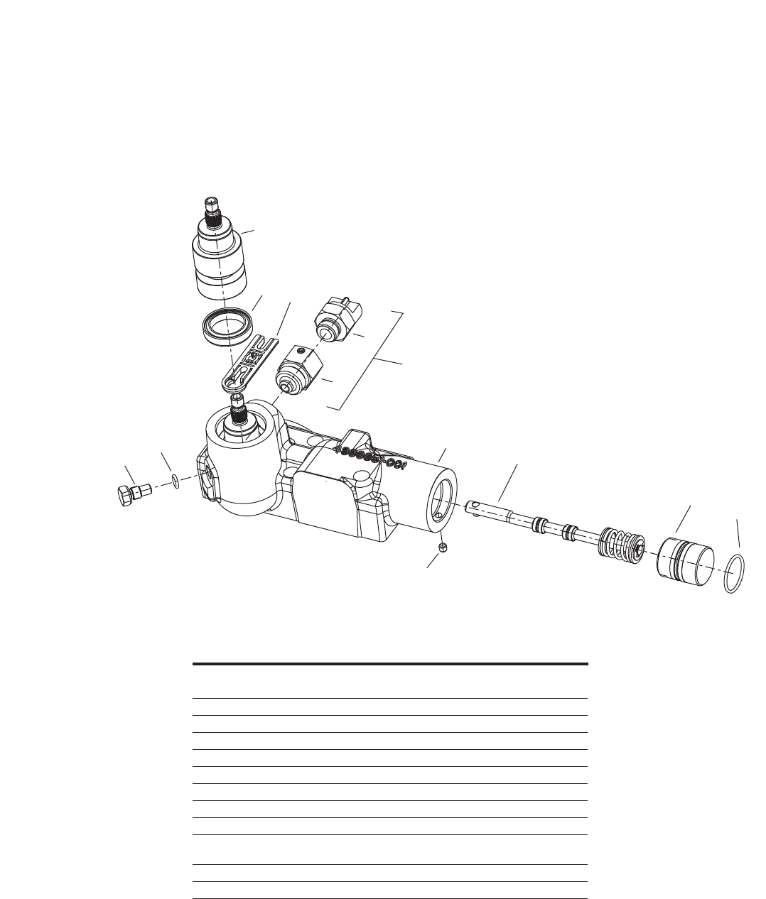
Item 64, 65
Mechanical Servo
High Gain
Controllers –
(MC, MF)*
MF Only
12
56
2
3
10
4
11
1 7
89
1 4999852-001(MC) 1 Housing, Control
4999852-002(MF)
2 4999852-001 1 Input Control Shaft Sub-Assembly
3 5987125-001 2 Plug
4 16133-2 3 O-Ring
5 72401-503 1 Seal, Shaft
6 5992233-001 1 Link, Feedback
7 4999884-003 1 Spool Sub-Assembly
8 72400-507 1 Plug
9 16015-8 1 O-Ring
10 102149-019 1 Set Screw
102149-019 2(MF)
11 72400-722 1 Adaptor Assembly, Neutral L/O (MF only)
12 109791-001 1 Switch, Neutral L/O (MF only)
REF PART NO. QTY. DESCRIPTION
Item 64, 65
Control Valve Sub-Assembly
*reference Index of Mechincal Servo Controllers on page 16.
19
EATON 350 Series Dual Path Mobile Pumps E-PUPI-TS006-E September 2007
Item 64, 65
Mechanical Servo
Neutral Lockout
Controllers –
(MD, ME)*
Neutral
Lockout
Switch
12
56
2
3
10
4
11
1 7
89
1 4999852-002 1 Housing, Control
2 5996108-001(MD) 1 Input Control Shaft Sub-Assembly
4999870-001(ME)
3 5987125-001 2 Plug
4 16133-2 3 O-Ring
5 72401-503 1 Seal, Shaft
6 5992233-001 1 Link, Feedback
7 4999884-001(MD) 1 Spool Sub-Assembly
4999884-002(ME)
8 72400-507 1 Plug
9 16015-8 1 O-Ring
10 102149-019 2 Set Screw
11 72400-722 1 Adaptor Assembly, Neutral L/O (MF only)
12 109791-001 1 Switch, Neutral L/O (MF only)
REF PART NO. QTY. DESCRIPTION
Item 64, 65
Control Valve Sub-Assembly
*reference Index of Mechincal Servo Controllers
on page 16.
20 EATON 350 Series Dual Path Mobile Pumps E-PUPI-TS006-E September 2007
ME, MF Only
12
56
2
3
14
15
13 10
16 17 19
13
4
11
1 7
89
1 4999852-003(MA, MB, MC, MD) 1 Housing, Control
4999852-004(ME, MF)
2 5996108-001(MA, ME) 1 Input Control Shaft Sub-Assembly
4999870-001(MB, MC, MD, MF)
3 5987125-001 2 Plug
4 16133-2 3 O-Ring
5 72401-503 1 Seal, Shaft
6 5992233-001 1 Link, Feedback
7 4999884-001(MA, ME) 1 Spool Sub-Assembly
4999884-002(MB, MF)
4999884-003(MC, MD)
8 72400-507 1 Plug
9 16015-8 1 O-Ring
10 102149-019 1 Set Screw
11 72400-722(ME, MF only) 1 Adaptor Assembly, Neutral L/O
12 109791-001(ME, MF only) 1 Switch, Netral L/O
13 16003-6 2 O-Ring
14 16148-316 2 Screw, Cap
15 16045-103 2 Washer, Lock
16 21607659 1 Valve
17 300AA00161A 1 Coil
18 72400-719 1 Manifold
19 20082 1 Nut
REF PART NO. QTY. DESCRIPTION
Item 64, 65
Control Valve Sub-Assembly — Destroke Valve Option 1
Item 64, 65
Mechanical Servo
Destroke Valve —
Option 1
(MA, MB, MC, MD,
ME, MF)*
*reference Index of Mechincal Servo Controllers on page 16.

21
EATON 350 Series Dual Path Mobile Pumps E-PUPI-TS006-E September 2007
ME, MF Only
12
56
2
3
14
15
13 10
16 17 19
13
4
11
1 7
89
1 4999852-003(MA, MB, MC,) 1 Housing, Control
4999852-004(MD, ME, MF)
2 5996108-001(MA, MD, ME) 1 Input Control Shaft Sub-Assembly
4999870-001(MB, MC, MF)
3 5987125-001 2 Plug
4 16133-2 3 O-Ring
5 72401-503 1 Seal, Shaft
6 5992233-001 1 Link, Feedback
7 4999884-001(MA, ME) 1 Spool Sub-Assembly
4999884-002(MB, MF)
4999884-003(MC, MD)
8 72400-507 1 Plug
9 16015-8 1 O-Ring
10 102149-019 1, 2(MD, ME, MF) Set Screw
11 72400-722(MD, ME, MF only) 1 Adaptor Assembly, Neutral L/O
12 109791-001(MD, ME, MF only) 1 Switch, Netral L/O
13 16003-6 2 O-Ring
14 16148-316 2 Screw, Cap
15 16045-103 2 Washer, Lock
16 21607659 1 Valve
17 300AA00250A 1 Coil
18 72400-719 1 Manifold
19 20082 1 Nut
REF PART NO. QTY. DESCRIPTION
Item 64, 65
Control Valve Sub-Assembly — Destroke Valve Option 2
Item 64, 65
Mechanical Servo
Destroke Valve —
Option 2
(MA, MB, MC, MD,
ME, MF)*
*reference Index of Mechincal Servo Controllers
on page 16.

22 EATON 350 Series Dual Path Mobile Pumps E-PUPI-TS006-E September 2007
ME, MF Only
12
56
2
3
14
15
13 10
16 17 19
13
4
11
1 7
89
1 4999852-003(MA, MB, MC,) 1 Housing, Control
4999852-004(MD, ME, MF)
2 5996108-001(MA,) 1 Input Control Shaft Sub-Assembly
4999870-001(MB, MC, MD, ME, MF)
3 5987125-001 2 Plug
4 16133-2 3 O-Ring
5 72401-503 1 Seal, Shaft
6 5992233-001 1 Link, Feedback
7 4999884-001(MA, ME) 1 Spool Sub-Assembly
4999884-002(MB, MF)
4999884-003(MC, MD)
8 72400-507 1 Plug
9 16015-8 1 O-Ring
10 102149-019 1, 2(MD, ME, MF) Set Screw
11 72400-722(MD, ME, MF only) 1 Adaptor Assembly, Neutral L/O
12 109791-001(MD, ME, MF only) 1 Switch, Netral L/O
13 16003-6 2 O-Ring
14 16148-316 2 Screw, Cap
15 16045-103 2 Washer, Lock
16 21607659 1 Valve
17 300AA00001A 1 Coil
18 72400-719 1 Manifold
19 20082 1 Nut
REF PART NO. QTY. DESCRIPTION
Item 64, 65
Control Valve Sub-Assembly — Destroke Valve Option 3
Item 64, 65
Mechanical Servo
Destroke Valve —
Option 3
(MA, MB, MC,
MD, ME, MF)*
*reference Index of Mechincal Servo Controllers on page 16.
23
EATON 350 Series Dual Path Mobile Pumps E-PUPI-TS006-E September 2007
ME, MF Only
12
56
2
3
14
15
13 10
16 17 19
13
4
11
1 7
89
1 4999852-003(MA, MB, MC,) 1 Housing, Control
4999852-004(MD, ME, MF)
2 499870-001 1 Input Control Shaft Sub-Assembly
3 5987125-001 2 Plug
4 16133-2 3 O-Ring
5 72401-503 1 Seal, Shaft
6 5992233-001 1 Link, Feedback
7 4999884-001(MA, ME) 1 Spool Sub-Assembly
4999884-002(MB, MF)
4999884-003(MC, MD)
8 72400-507 1 Plug
9 16015-8 1 O-Ring
10 102149-019 1, 2(MD, ME, MF) Set Screw
11 72400-722(MD, ME, MF only) 1 Adaptor Assembly, Neutral L/O
12 109791-001(MD, ME, MF only) 1 Switch, Netral L/O
13 16003-6 2 O-Ring
14 16148-316 2 Screw, Cap
15 16045-103 2 Washer, Lock
16 21607659 1 Valve
17 300AA00002A 1 Coil
18 72400-719 1 Manifold
19 20082 1 Nut
REF PART NO. QTY. DESCRIPTION
Item 64, 65
Control Valve Sub-Assembly — Detroke Valve Option 4
Item 64, 65
Mechanical Servo
Destroke Valve —
Option 4
(MA, MB, MC,
MD, ME, MF)*
*reference Index of Mechincal Servo Controllers
on page 16.
24 EATON 350 Series Dual Path Mobile Pumps E-PUPI-TS006-E September 2007
Orifices Sizes
Available
Last two digits
of dash number
stamped on face
of orifice.
XX
101619-021 0,53 [.021]
101619-024 0,61 [.024]
101619-028 0,71 [.028]
101619-032 0,81 [.032]
101619-036 0,91 [.036]
101619-040 1,02 [.040]
101619-044 1,12 [.044]
101619-052 1,32 [.052]
101619-057 1,45 [.057]
101619-065 1,65 [.065]
HOLE DIA.
PART NO. mm [inches]
Item 83 -
Charge Pump
Adapter Assembly
cm3/r [in/r] mm [in]
13,9 [0.85] 13,9 [0.85] R - rotation 5991128-005 5991128-001
L - rotation 5991230-005 5991230-001
17,4 [1.06] 17,4 [1.06] R - rotation 5991128-006 5991128-002
L - rotation 5991230-006 5991230-00
21 [1.28] 21 [1.28] R - rotation 5991128-007 5991128-003
L - rotation 5991230-007 5991230-003
23,1 [1.40] 23,1 [1.40] R - rotation 5991128-008 5991128-004
L - rotation 5991230-008 5991230-004
GEROTOR POCKET DEPTH
DEPTH OF REMOTE SUCTION
DISPLACEMENT POCKET ROTATION FILTER CHARGE FILTER
PART NO. DISPLACEMENT
NUMBER ITEM 1 ITEM 2 cm3/r [in/r]
5987263-001 5987262-001 5989547-001 13,9 [0.85]
5987263-002 5987262-002 5989547-002 17,4 [1.06]
5987263-003 5987262-003 5989547-003 21 [1.28]
5987263-004 5987262-004 5989547-004 23,1 [1.40]
Gerotor Sizes
Available

25
EATON 350 Series Dual Path Mobile Pumps E-PUPI-TS006-E September 2007
Required Tools
Assembly
9/16 in. Hex Key (Allen)
7/16 in. End Wrench
9/16 in. End Wrench
3/4 in. End Wrench
1 in. End Wrench
9/16 in. Socket
3/4 in. Socket
7/16 in. Socket
Adjustable-grip pliers
Snap-ring pliers
Internal Retaining Ring Pliers
(straight .070 tip)
Internal Retaining Ring Pliers
(straight .090 tip)
External Retaining Ring Pliers
(straight .090 tip)
9/32 in. Retaining E-ring,
Applicator
1/2 in. Retaining E-ring,
Applicator
O-Ring Pick
Torque Wrench
(145 ±10 N/m – 107 ± 7lb/ft
capacity)
Rubber Mallet
Light Petroleum Jelly
Seal Driver
Arbor press
Loctite (#247 and #290 or
equivalent)
EZ-Clip Tool
Seat Installation Tool
Locking C-Clamp
26 EATON 350 Series Dual Path Mobile Pumps E-PUPI-TS006-E September 2007
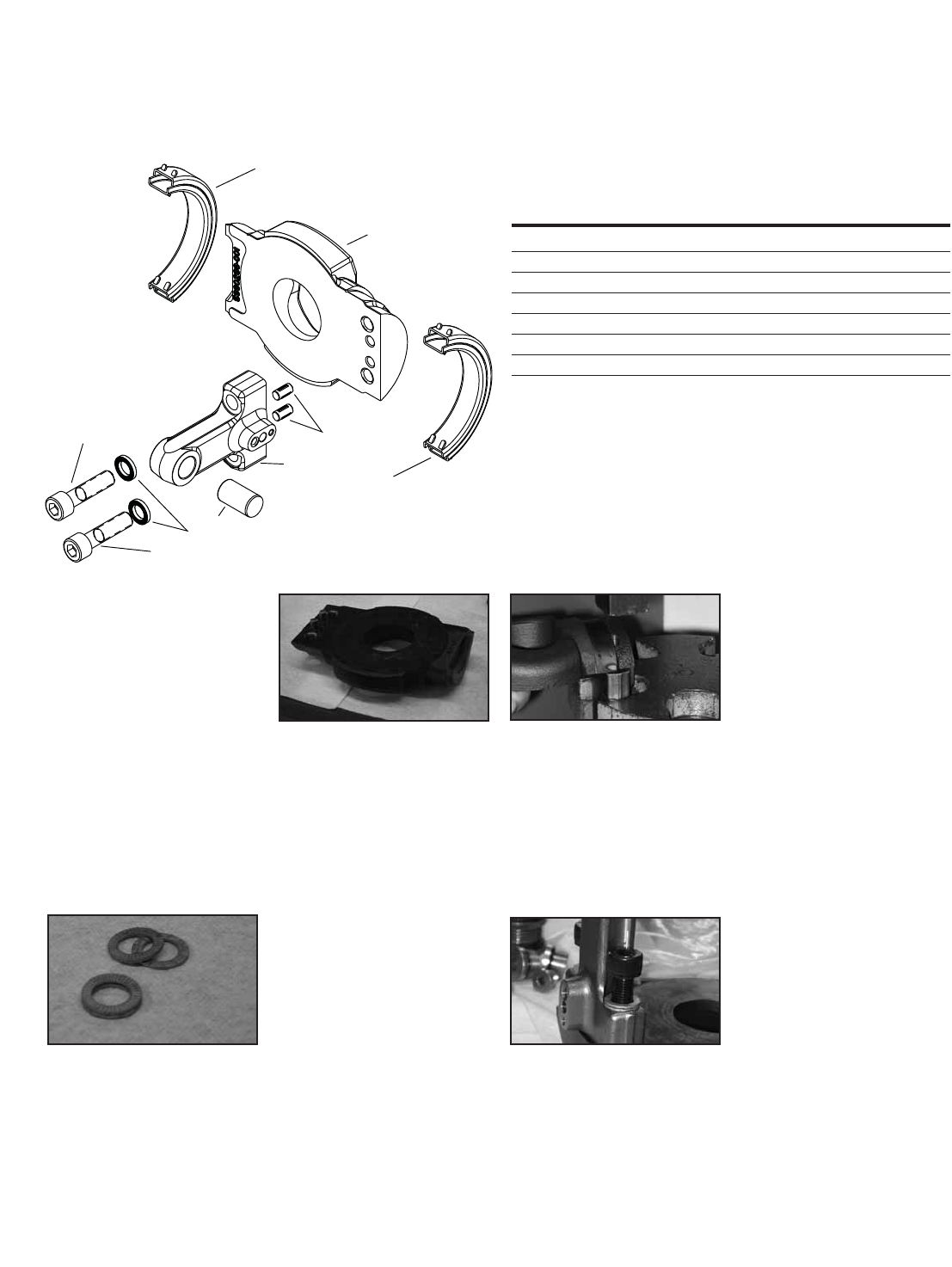
Assembly
Swash Plate
Sub-Assembly
Step 1
Press 15mm diameter dowel
pin (item 5) into opening at
end of swash arm (item 2).
Step 2
Insert 2 Drive-Lok dowel pins
(item 6) into smooth-bore holes
in swash plate (item 1).
Step 3
Align smooth-bore holes in flat
surface of swash arm with
Drive-Lok pins; fit swash arm
to swash plate and press parts
togetherwith an arbor press.
Step 4
Place assembled swash plate
and swash arm on a stable
work surface, with swash arm
pointing up.
Step 5
Fit together two Nord-Lock
washers (item 3) so that
the stepped faces match, and
the faces with radial teeth face
out. Assemble another pair of
washers the same way.
Step 6
Place one pair of washers on
each shoulder of the swash
arm, aligned with the threaded
holes.
Step 7
Insert an M10 x 1.25 x 40mm
socket-head cap screw (item 4)
through each pair of washers
and into threads; tighten to 79
n/m (58 lb/ft).
Note:
Disassembly of the Swash Plate
and Manual Servo Controller is
the reverse of the assembly
processes outlined starting on
page 25 in this manual.
4
4
3
5
2
6
1
7
7
1 5990297-001 1 Swashplate
2 4999620-001 1 Arm, Swash
3 5987468-016 2 Washer, Nord-Lock
4 5996773-040 2 Hex Socket Head Cap Screw
5 5986958-001 1 Dowel Pin
6 5987967-001 2 Driv-Lok Pin
7 5991097-001 2 Bearing, Swash
REF PART NO. QTY. DESCRIPTION
27
EATON 350 Series Dual Path Mobile Pumps E-PUPI-TS006-E September 2007
Step 5
Insert a feedback link (item 6),
keyhole opening first, through
the flat side of the control
housing.
Step 6
On one side, turn the control
input shaft; on the other side,
guide the head pin into the
keyhole opening on the
feedback link; turn until
connection is secure.
Step 7
Insert a control spool sub-
assembly (item 7) through the
spoolbore on the control housing
(item 1).
Step 8
Once the control spool shaft is
fully inserted, turn the spool
until the dowel pin faces up.
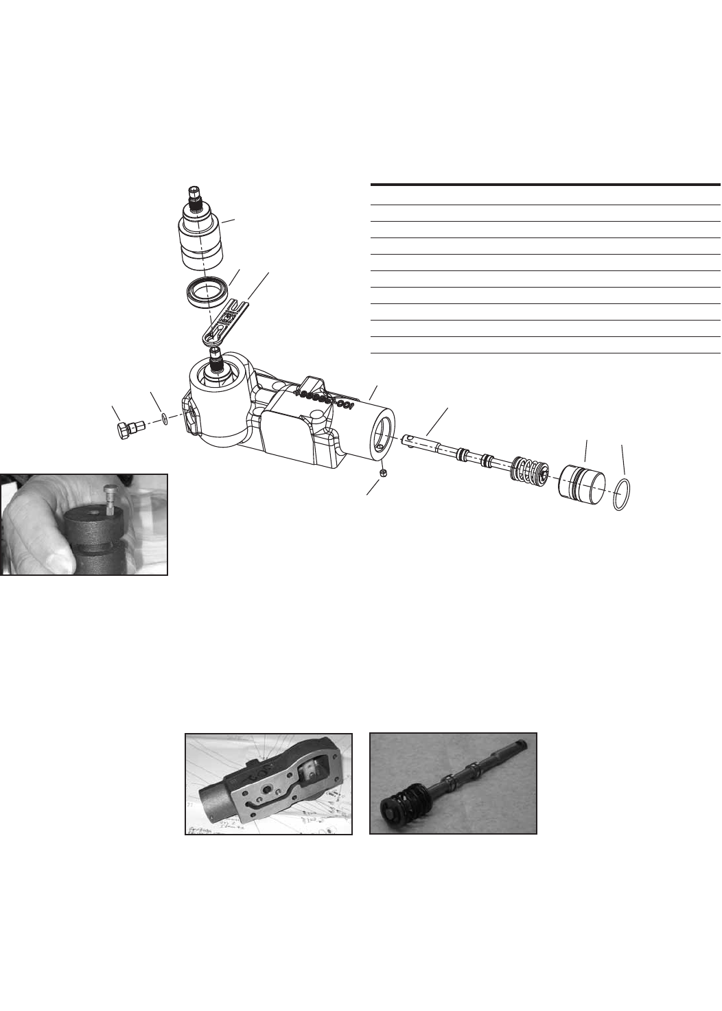
Assembly
Mechanical
Servo Control
Assembly
Step 1
Insert the knurled end of a
4mm head pin 4999869-001
in the smooth-bore hole on a
control input shaft (item 2).
Step 2
Press the head pin into place
with an arbor press.
Step 3
Fit the control input shaft, head
pin first, into a control housing
(item 1).
Step 4
With the control input shaft in
place, turn over the control
housing.
Note:
Disassembly of the Swash Plate
and Manual Servo Controller is
the reverse of the assembly
processes outlined starting on
page 25 in this manual.
56
2
3
10
41 7
89
1 1 Housing, Control
2 1 Input Control Shaft Sub-Assembly
3 2 Plug
4 3 O-Ring
5 1 Seal, Shaft
6 1 Link, Feedback
7 1 Spool Sub-Assembly
8 1 Plug
9 1 O-Ring
10 1 Set Screw
REF PART NO. QTY. DESCRIPTION
28 EATON 350 Series Dual Path Mobile Pumps E-PUPI-TS006-E September 2007
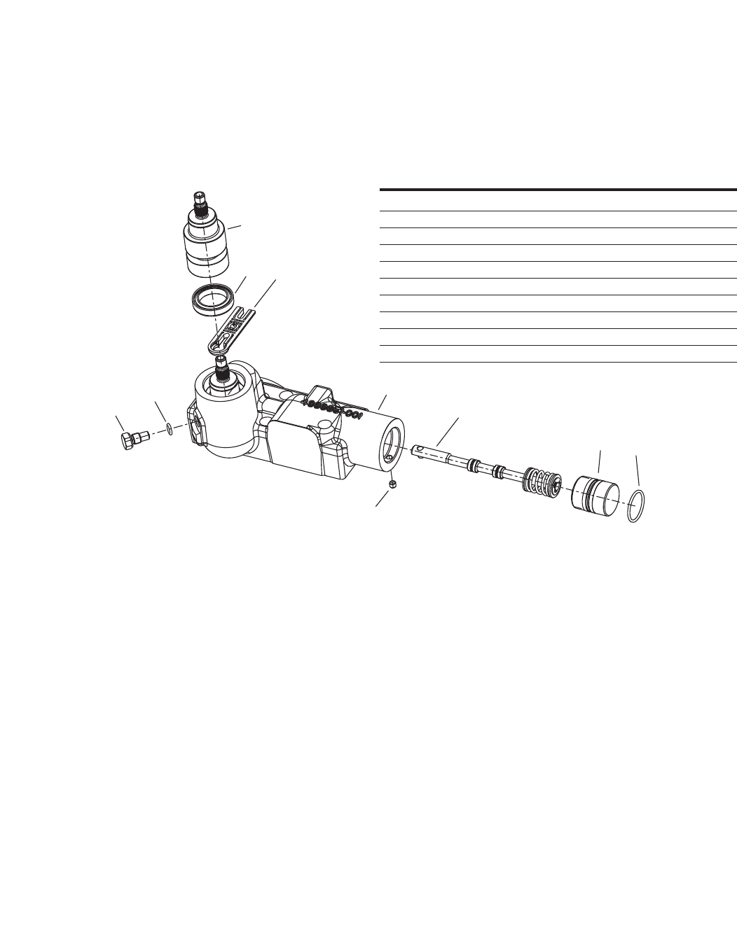
Assembly
Mechanical
Servo Control
Assembly
Step 9
Align the center hole on the
feedback link with the dowel pin
on the control spool. Press the
feedback link (item 6) onto
the dowel pin until the end
of the dowel pin is flush with
the surface of the feedback link.
Step 10
Fit an O-Ring (item 4) under the
head of a threaded retaining
plug (item 3). Lubricate the
O-Ring.
Step 11
Align the 6.35mm groove in the
control input shaft with the
threaded hole on the control
housing.
Step 12
Insert the retaining plug (item 3)
in the threaded hole; make sure
the plug fits in the 6.35mm
groove. Tighten to 11 n/m (8 lb-ft).
Step 13
Fit an O-Ring (item 9) in the cen-
ter groove on a spool bore plug
(item 8). Insert the plug, thread-
ed end first, in the spool bore; it
should fit around the spring end
of the spool shaft sub-assem-
bly.
Step 14
Using adjustable-grip pliers, turn
the spool bore plug until there
is no play where the spool shaft
meets the feedback link. Adjust
tightness as needed; both
under-tightening and over-tight-
ening the plug will result in
unwanted play.
Step 15
Insert a 4.7mm set screw (item
10) in the threaded hole near
the end of the spool shaft port.
Tighten to 3 n/m (2.2 lb-ft).
Step 16
Fit a control input shaft seal
(item 5) over the exposed end
of the control input shaft; using
a seal installation tool, press
down on the seal until it is flush
with the face of the input shaft
port. (Note: If necessary, use a
shaft coupler to press the seal
into place).
56
2
3
10
41 7
89
1 1 Housing, Control
2 1 Input Control Shaft Sub-Assembly
3 2 Plug
4 3 O-Ring
5 1 Seal, Shaft
6 1 Link, Feedback
7 1 Spool Sub-Assembly
8 1 Plug
9 1 O-Ring
10 1 Set Screw
REF PART NO. QTY. DESCRIPTION
29
EATON 350 Series Dual Path Mobile Pumps E-PUPI-TS006-E September 2007
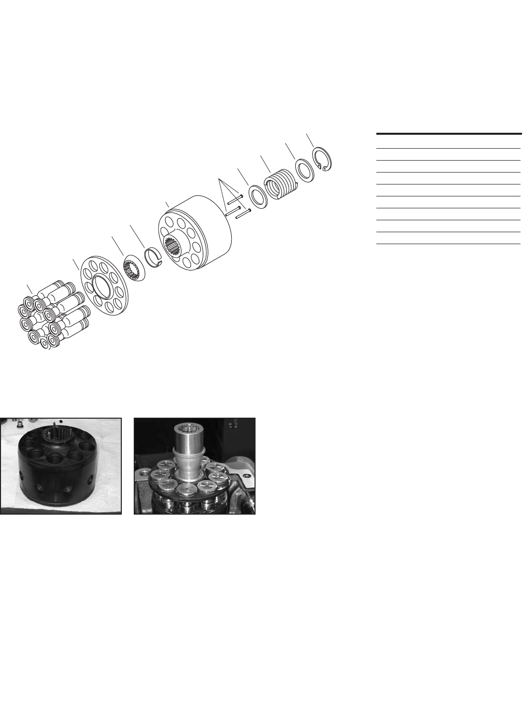
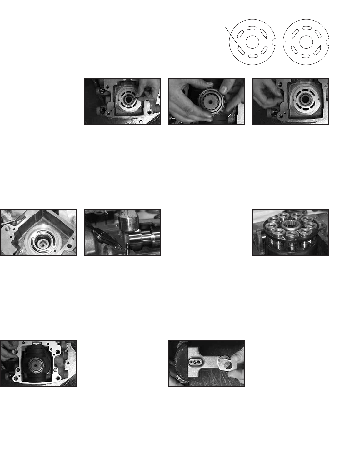
Assembly
Rotating Kit
Assembly
1
2
3
5
4
678
9
7
1 9 Piston Sub-Assembly
2 1 Shoe Retainer
3 1 Pivot
4 1 Load Pin Keeper
5 1 Cylinder Barrel
6 3 Loading Pin
7 2 Washer
8 1 Spring
9 1 Internal Retaining Ring
REF QTY. DESCRIPTION
Step 1
To reassemble the rotating kit
assembly, complete the following:
Compress the pin keeper (item
4) and install in the spline of the
cylinder barrel. Install the three
pins (item 6) with head end to
the inside of the barrel and
position in the special grooves
of the cylinder barrel spline.
Step 2
Install the washer, spring, and
second washer into the cylinder
barrel. Use the two 3/8 in. I.D.
washers, nut and 3/8 in. x 3-1/4
in. cap screw to compress the
spring and retain with retaining
ring. Remove the nut, cap
screw, and the two washers.
Step 3
Install the pivot (item 3) onto
the three pins, shoe retainer
onto he pivot, and piston
assemblies thru the shoe
retainer and into cylinder
barrel, resting on shoe
retainer.
Step 4
Insert (9) piston assemblies
41cc (2.50 cid) - 4994911-001
49cc (3.00 cid) - 4994908-001
62cc (3.8 cid) - 4994583-001
into the shoe retainer
4994890-001 41/49cc (2.50/3.0cid)
4994892-001 62cc (3.8cid)
so that the brass swivels face up.
Insert the pivot into the shoe
retainer from beneath so that
the tapered faces match.
Holding the pivot in place,
lower the piston assemblies
into their respective cylinders.
The pivot should rest on the
three loading pins.
30 EATON 350 Series Dual Path Mobile Pumps E-PUPI-TS006-E September 2007
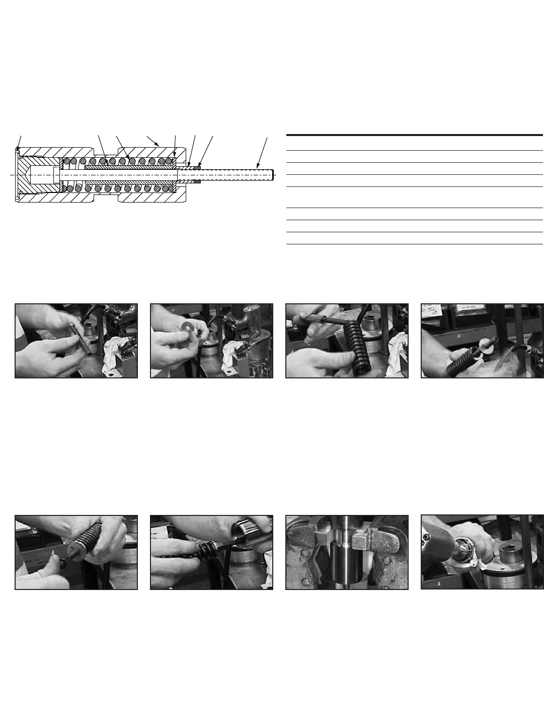
Assembly
Servo Piston
Assembly
Step 1
Hold a servo piston bolt (item 4)
head end down, on a work
surface.
Step 2
Slide a spring retaining washer
(item 2) onto the servo piston
bolt so that the stamped word
“IN” faces up, toward where
the spring will go.
Step 3
Slide the spring (item 6) and
springstop over the bolt so that
both parts rest on the spring
retaining washer.
Note: If assembling a HRC
controlled pump, a second
spring will be installed in place
of the displacement limiter.
Step 4
Place the second spring retaining
washer (item 2) over the servo
piston bolt, with the stamped
word “IN” facing the spring.
Step 5
Thread a spring compression
nut (item 7) onto the servo
piston bolt, with the inside
counterbored (smooth) end
facing the spring. Tighten the
spring compression nut until
it is snug against the spring
retaining washer.
Step 6
Insert the servo piston bolt
assembly into the piston (item 1),
threaded end first.
Step 7
Thread a piston plug (item 3) into
the open end of the servo piston.
Step 8
Using a vise and two pieces
of shim stock, grip the piston by
the recessed groove. Do not
mar the rounded surfaces of
the servo piston.
Step 9
Tighten the piston plug (item 3)
to 71±3 n/m (52.4±2.2 lb-ft).
31526784
1 5989957-001 1 Servo Piston
2 5989955-001 2 Spring Retainer
3 4999972-001 1 Plug, Servo Piston
4 5989956-001 1 Servo Piston Bolt
5 5989958-001 1 Spring Stop
5989954-001
6 5989952-001 1 Spring
7 72400-542 1 Nut, Hex
8 16024-6 1 Thin Finished Hex Nut, UNF
REF PART NO. QTY. DESCRIPTION
31
EATON 350 Series Dual Path Mobile Pumps E-PUPI-TS006-E September 2007
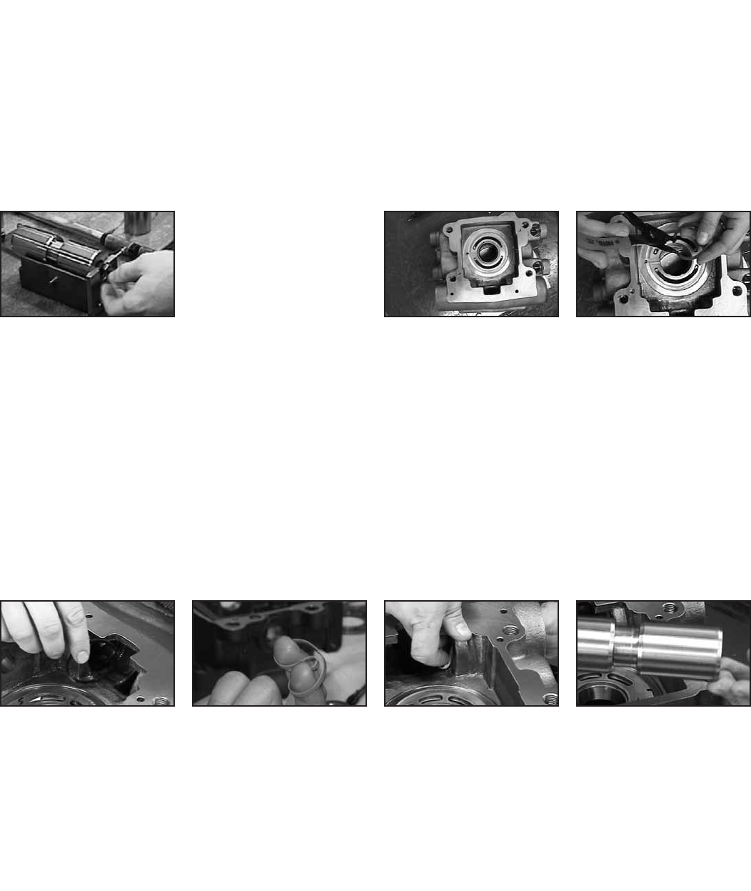
Step 3
Compress a piston backup ring
5987241-001 and insert it in the
servo piston bore, which is
perpendicular to the bearing bore;
let the backup ring expand into
the seal groove.
Step 4
Insert a Teflon glide ring
5987241-001 in the same way,
so that it fits in the seal groove
inside the backup ring.
Step 5
Using the same method,
install backup rings and Teflon
glide rings in the other side of
the servo piston bore.
Step 6
Lubricate the leading edge of
a servo piston assembly, and
insert it in the piston bore. The
threaded servo piston bolt
should extend about 20mm
(.80 in) beyond the housing.
Assembly
Servo Piston/
Dual Pump Housing
Assembly
Step 10
Thread a locking nut (item 8)
onto the servo piston bolt
until it fits against the spring
compression nut.
Step 11
Apply one drop of Loctite 290
to the threads of the servo
piston bolt where the spring
compression nut and locking
nut will meet.
Step 12
This step may require two people:
Using a 5mm hex key, hold the
servo piston bolt steady, then
use two 9/16-inch open-ended
wrenches to tighten the locking
nut against the spring compres-
sion nut. The servo piston bolt
should turn freely but should
not move in or out of the
servo piston.
Step 1
Place the center housing on a
stable work surface.
Step 2
Using snap-ring pliers, insert a
snap ring 16077-33 in each
of the two grooves inside the
bearing bore.
Dual Pump Housing
Assembly
32 EATON 350 Series Dual Path Mobile Pumps E-PUPI-TS006-E September 2007
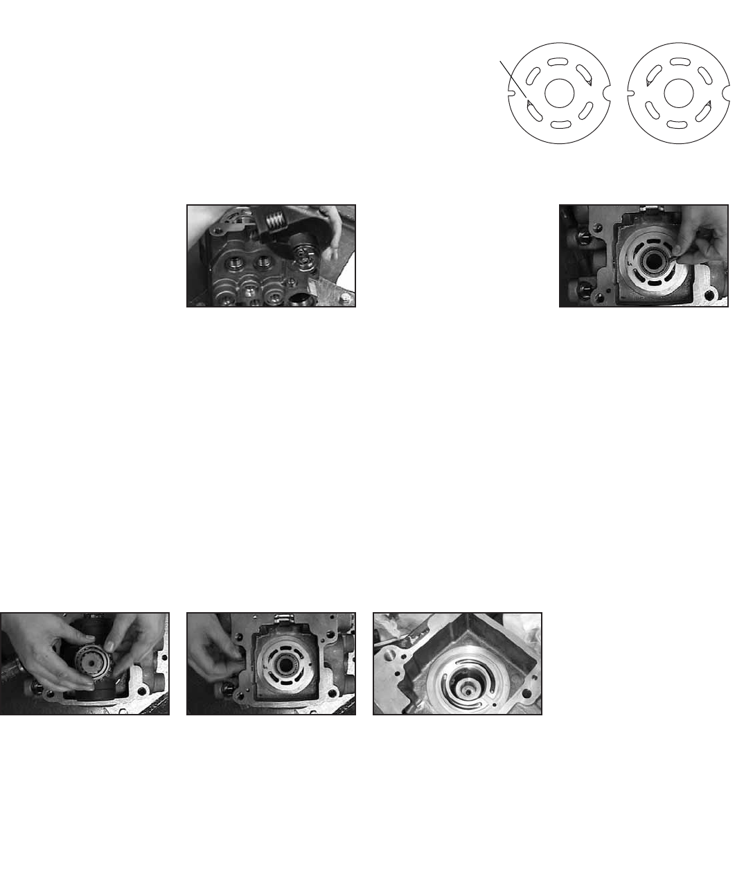
Note "V"
notch
locations
Valve Plate
Identification
Lefthand Rotation Righthand Rotation
Assembly
Rear Pump
Assembly
Step 7
Fit an O-Ring (p/n 16015-34) in
the groove on a servo cap plug
5989898-001.
Step 8
Place the servo cap plug over
the servo piston bolt, and turn
the servo cap plug until tight.
Torque will be adjusted later.
Step 9
Turn the housing so that the
bearing bore faces up.
Step 10
Insert a roll pin 16026-610 into
the guide hole near the bearing
bore; tap it in firmly with a rub-
ber mallet.
Step 11
Insert 52mm tapered roller
bearing 5988197-001 in bearing
bore, with taper narrowing from
top to bottom; bearing cup
should rest on snap ring.
Step 12
Set the valve plate (Refer to
item 18, page 5 and item 31,
page 6 for part numbers) over
the bearing bore, aligning the
notch with the roll pin.
Step 13
For a pump with left-hand
rotation, the front valve plate
should also have left-hand
rotation, and vice versa for
right-hand rotation. The valve
plates are labeled according
to direction.
REFERENCE VALVE PLATE
IDENTIFICATION ABOVE
Step 14
Insert roll pins (p/n 16026-810)
in the two guide holes for the
gasket. Tap them firmly in place
with a rubber mallet.
33
EATON 350 Series Dual Path Mobile Pumps E-PUPI-TS006-E September 2007
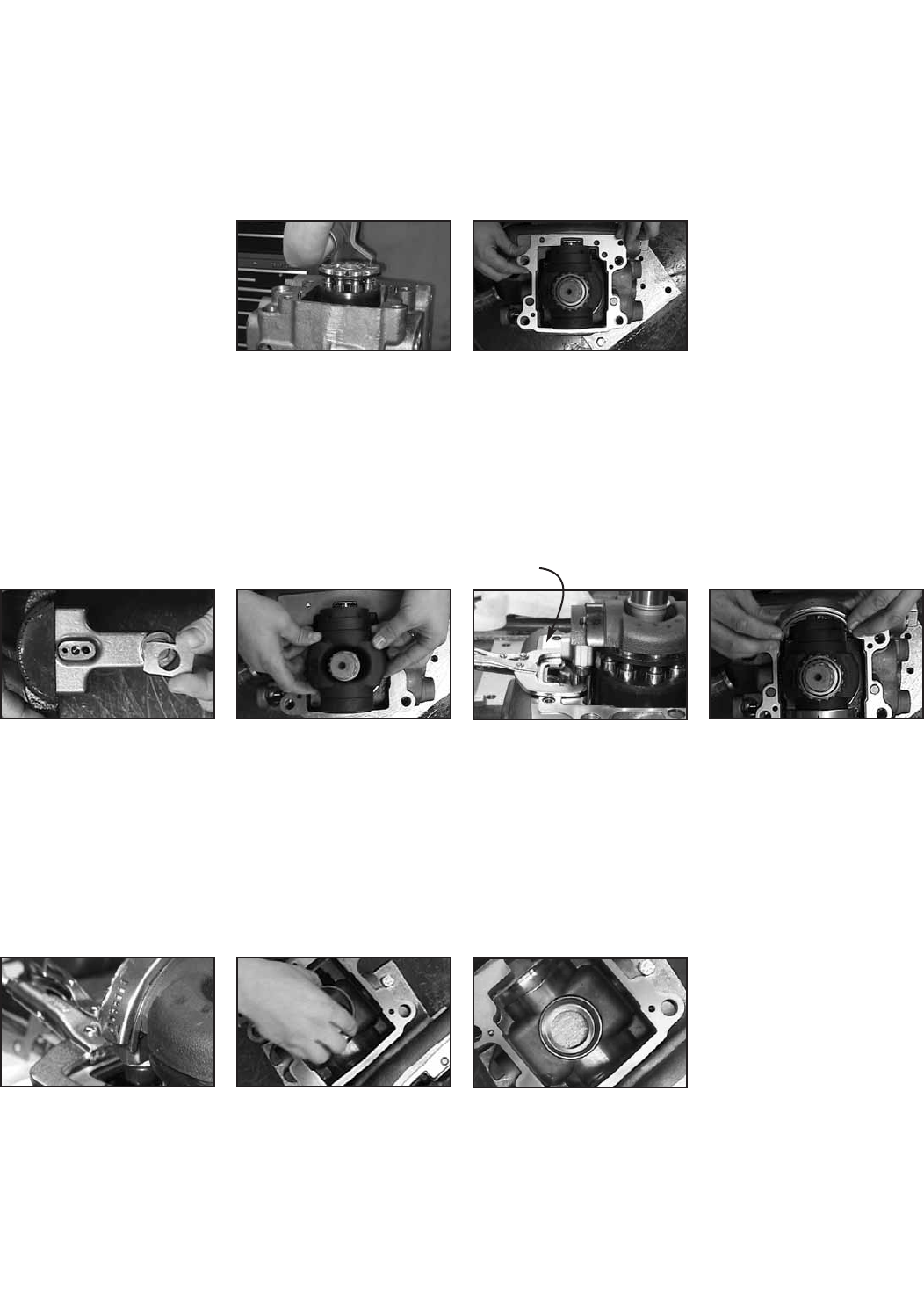
Assembly
Rear Pump
Assembly
Step 15
Lubricate the valve plate and
each piston bore in the cylinder
barrel with clean hydraulic fluid.
Step 16
Center the cylinder barrel on
the valve plate with the brass
shoes facing up; apply clean
hydraulic fluid to the brass
shoes.
Step 17
Set the gasket 5984712-001 on
the roll pins.
Step 18
Insert the rear pump shaft
through the rotating kit until it
engages the spline.
Step 19
Place a follower 4999637-001
over the dowel pin on one of
the swash arms.
Step 20
Lower the swash plate assembly
into the housing so that the flat
side of the plate rests on the
brass shoes, and the follower
4999637-001 fits in the groove
on the servo piston.
Step 21
Level the swash plate by hand,
and use a locking C-clamp on
the swash arm to keep the
assembly from moving.
Step 22
Apply petroleum jelly to the
inner faces of the cradle
bearings 5991097-001.
Step 23
Slide one cradle bearing onto
each end of the swash plate, so
that the alignment tabs engage
and the cradle bearings are
held in place.
Step 24
Set the bearing cone 5988197-
001 on the rear pump shaft,
with the narrow side up.
Step 25
Apply petroleum jelly to the
outside of the cup side of the
taper bearing and place it in
the bearing bore of the rear
flange.
Step 26
Remove the locking C-clamp,
taking care not to tip the swash
plate assembly.
Locking
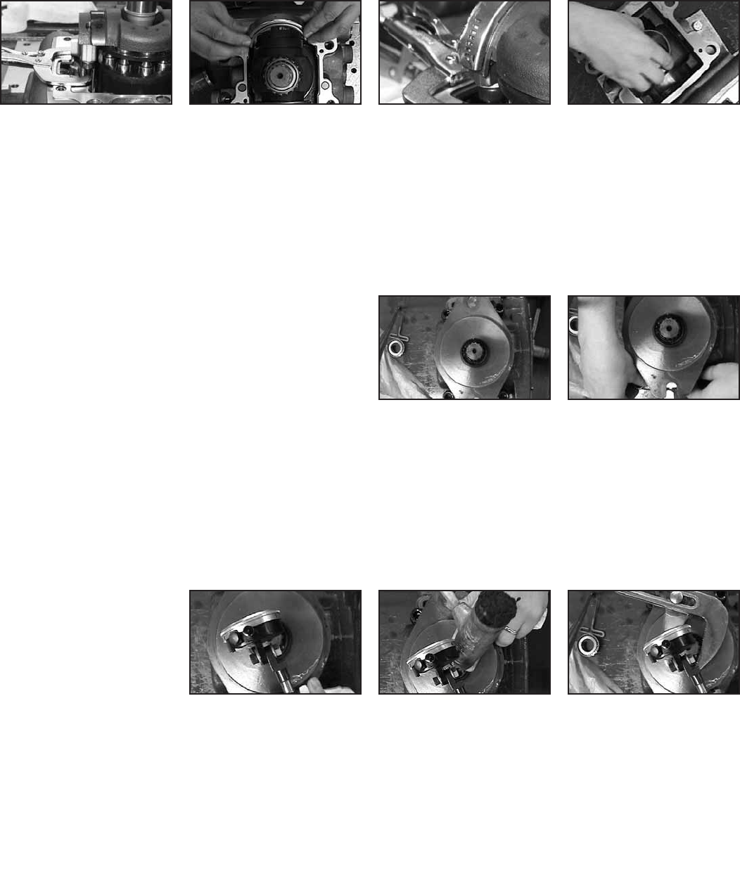
C-Clamp
34 EATON 350 Series Dual Path Mobile Pumps E-PUPI-TS006-E September 2007
Assembly
Rear Pump
Assembly
Step 27
Turn the rear flange over and
place it on the housing. Lower
the flange in place so that the
bolt holes are aligned.
Step 28
Insert a 16mm x 45mm socket-
head cap screw 114978-045 in
each of the four bolt holes;
tighten them to 145±10 n/m
(107±7 lb-ft).
Step 29
Turn the assembled housing
and flange so that the rear
pump shaft is horizontal.
Step 30
Measure the shaft end play:
Place a dial indicator with a
magnetic base on the face of
the rear flange, and set the
rod tip on the end of the rear
pump shaft.
Step 31
Tap the end of the shaft with a
rubber mallet, and set the dial
indicator to zero. Then tap the
other end of the shaft and record
the result.
Step 32
Subtract 0.05mm from the
recorded measurement; this will
be the thickness of the required
shim stack.
Step 33
Loosen the cap screws 114978-
045 from the rear flange, then
remove the flange from the
housing and set it aside. Hold
the swash arm in place with a
locking C-clamp.
Step 34
Combine shims to reach the
required thickness.
Step 35
Remove the taper bearing cup
from the flange, and place the
shims in the bearing bore. Set
the bearing cup back in place on
top of the shim stack.
Step 36
Set the rear flange on the housing
again; insert the cap screws
114978-045, remove the locking
clamp, and tighten the cap
screws to 145±10 n/m (107±7
lb-ft).
35
EATON 350 Series Dual Path Mobile Pumps E-PUPI-TS006-E September 2007
Assembly
Front Pump
Assembly
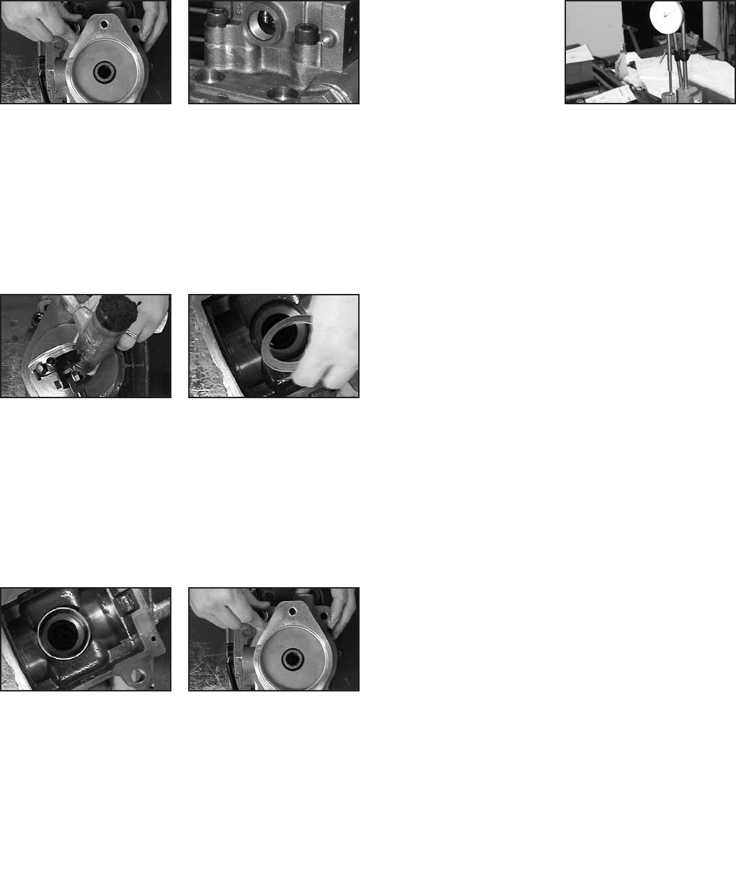
Step 1
Turn the housing so that the
bearing bore faces up.
Step 2
Insert a roll pin 16026-610 into
the guide hole near the bearing
bore; tap it in firmly with a
rubber mallet.
Step 3
Insert 52mm tapered roller
bearing 5988197-001 in bearing
bore, with taper narrowing from
top to bottom; bearing cup
should rest on snap ring.
Step 4
Set the valve plate (Refer to
Item 18, page 5 for part number)
over the bearing bore, aligning
the notch with the roll pin.
Step 5
For a pump with left-hand
rotation, the front valve plate
should also have left-hand
rotation, and vice versa for
right-hand rotation. The valve
plates are labeled according
to direction.
REFERENCE VALVE PLATE
IDENTIFICATION ABOVE
Step 6
Insert roll pins 16026-810 in the
two guide holes for the gasket.
Tap them firmly in place with a
rubbermallet.
Step 7
Lubricate the valve plate and
each piston bore in the cylinder
barrel with clean hydraulic fluid.
Step 8
Center the cylinder barrel on
the valve plate with the brass
shoes facing up; apply clean
hydraulic fluid to the brass
shoes.
Step 9
Set the gasket 5989712-001 on
the roll pins.
Step 10
Insert the front pump shaft
through the rotating kit until it
engages the spline.
Step 11
Place a follower 4999637-001
over the dowel pin on one of
the swash arms.
Step 12
Lower the swash plate assembly
into the housing so that the flat
side of the plate rests on the
brass shoes, and the follower
fits in the groove on the servo
piston.
Note "V"
notch
locations
Valve Plate
Identification
Lefthand Rotation Righthand Rotation
36 EATON 350 Series Dual Path Mobile Pumps E-PUPI-TS006-E September 2007
Assembly
Front Pump
Assembly
Step 13
Level the swash plate by hand,
and use a locking C-clamp on
the swash arm to keep the
assembly from moving.
Step 14
Apply petroleum jelly to the
inner faces of the cradle
bearings (p/n 5991097-001).
Step 15
Slide one cradle bearing
5991097-001 onto each end of
the swash plate, so that the
alignment tabs engage and the
cradle bearings are held in
place.
Step 16
Set the bearing cone on the
rear pump shaft, with the
narrow side up.
Step 17
Apply petroleum jelly to the
outside of the cup side of the
taper bearing and place it in
the bearing bore of the front
flange.
Step 18
Remove the locking C-clamp,
taking care not to tip the
swash plate assembly.
Step 19
Turn the flange over and place
it on the housing. Lower the
flange in place so that the bolt
holes are aligned.
Step 20
Insert a 16mm x 45mm socket-
head cap screw 114978-045 in
each of the four bolt holes;
tighten them to 145 ± 10 n/m
(107 ± 7lb-ft).
Step 21
Fix the assembled housing to
the work surface.
Step 22
Measure the shaft end play:
Place a dial indicator with a
magnetic base on the face of
the front flange, and set the
rod tip on the end of the front
pump shaft.
Step 23
Tap the end of the shaft with a
rubber mallet, and set the dial
indicator to zero.
Step 24
Using adjustable grip pliers or
other suitable tool, pry the shaft
end up and record the result on
the dial indicator.
37
EATON 350 Series Dual Path Mobile Pumps E-PUPI-TS006-E September 2007
Assembly
Front Pump
Assembly
Step 25
Subtract 0.05mm from the
recorded measurement; this will
be the thickness of the required
shim stack.
Step 26
Loosen the cap screws114978-
045 from the front flange, then
remove the flange from the
housing and set it aside. Hold
the swash arm in place with a
locking C- clamp.
Step 27
Combine shims to reach the
required thickness.
Step 28
Remove the taper bearing cup
from the flange, and place the
shims in the bearing bore. Set
the bearing cup back in place
on top of the shim stack.
Step 29
Set the front flange on the
housing again; insert the cap
screws, remove the locking
clamp, and tighten the cap
screws to 145±10 n/m
(107±7 lb-ft).
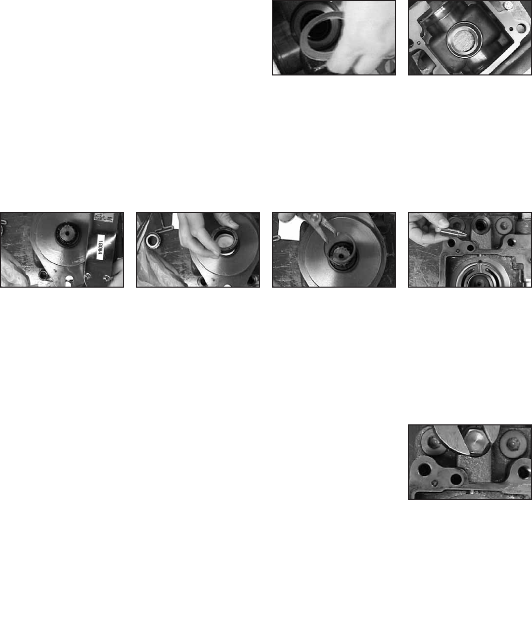
Step 30
Slide the shaft seal (Refer to
Item 28, page 5 for part num-
bers) over the end of the front
shaft. Carefully push the shaft
seal down into the bore until
the snap ring groove is visible.
Step 31
Compress a snap ring16077-028
and insert it in the bore. Press
down on the snap ring until it
engages the groove, approxi-
mately 5mm below the chamfer
at the top of the bore.
Step 32
Insert the charge relief poppet
4998532-001 into the charge
relief bore.
Step 33
Insert the charge relief spring
4998533-001 into the charge
relief poppet.
Step 34
Apply an O-Ring 16133-10 to a
charge relief valve plug 72400-
658 and work it under the head
of the plug.
Step 35
Apply petroleum jelly to the
charge relief valve plug.
Step 36
Place the plug on the exposed
end of the spring, and compress
the spring until the plug threads
engage the bore threads.
Tighten the plug to 39 n/m
(28.8 lb-ft).
38 EATON 350 Series Dual Path Mobile Pumps E-PUPI-TS006-E September 2007
Assembly
Front Pump
Assembly
Step 37
Insert a high-pressure relief
valve in the first pressure relief
port. Tighten to 143 n/m
(105.5 lb-ft).
Step 38
Repeat process for other three
pressure relief valves and ports.
Step 39
Assemble a speed sensor: Slide
an O-Ring 4995422-001 on the
straight end of the sensor
(Refer to Item 55, page 5 for
part number), place a washer
16048-077 and snap ring
16120-125 on the plug end of
the sensor.
Step 40
Insert the sensor sub-assembly
in the speed sensor port. Using
snap-ring pliers, work the snap
ring into port until it engages
the snap ring groove.
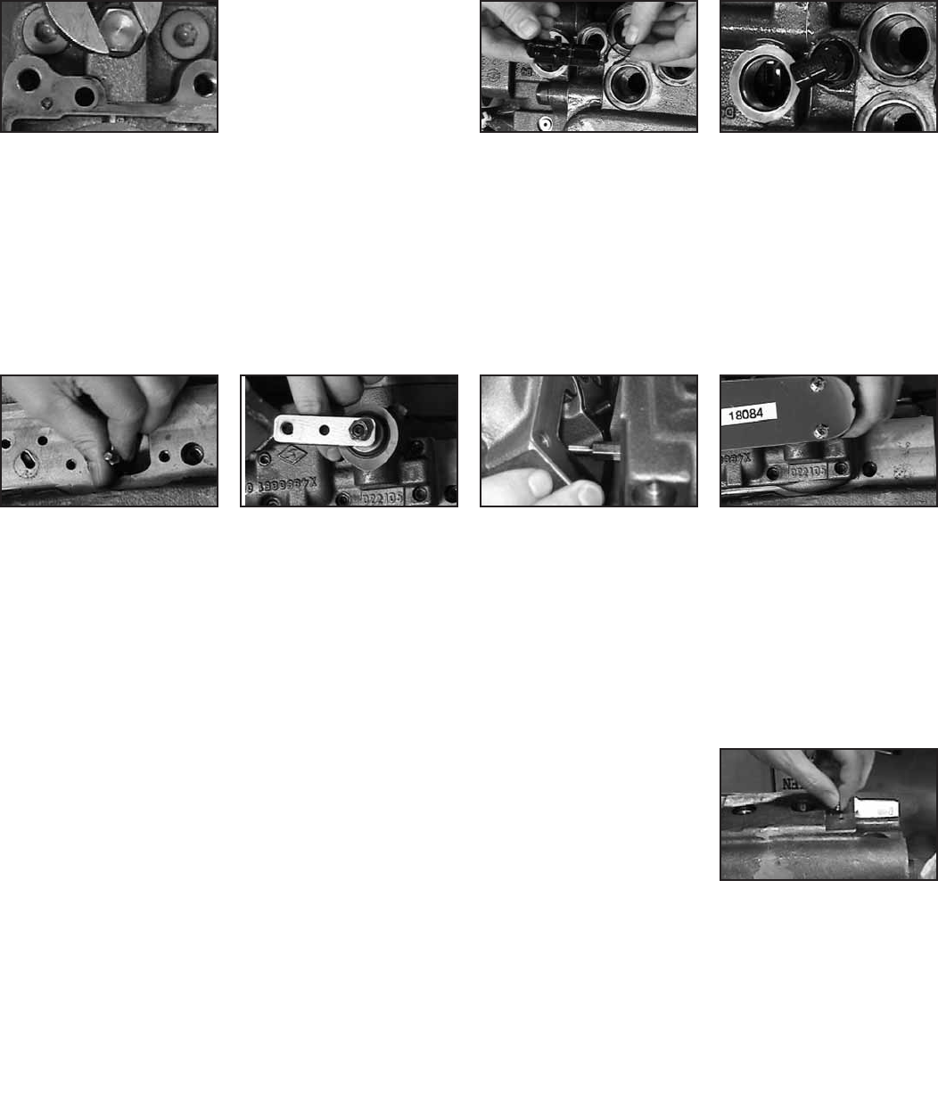
Assemble the Controller
Step 41
Insert a feedback pin 4999960-
001 through each 17mm hole
on the two controller mounting
faces. Using a 5/16-inch socket,
tighten each feedback pin to
14 n/m (10.3 lb-ft).
Step 42
Insert an M6 x 25mm socket-
head cap screw 114975-025
in each of (6) holes in the
controller housing.
Step 43
Place the controller gasket
5987239-001 over the exposed
ends of the cap screws.
Step 44
Lift the controller housing
toward the controller mounting
face, taking care not to let the
gasket or screws fall.
Step 45
Align the feedback link inside
the controller housing with the
feedback pin extending from the
mounting plate. Tighten the
screws to 14 n/m (10.3 lb-ft).
Displacement Limiters
Step 46
If the pump includes displace-
ment limit ports, insert a
displacement limiting screw
16139-644 in each of the two
larger ports.
Step 47
Install a sealing nut 5996839-
001 over each displacement
limiting screw and tighten to
16 n/m (11.8 lb-ft).
Step 48
Repeat this process for the two
smaller displacement limit ports,
tightening the sealing nuts
5996838-001 to 9 n/m (6.6 lb-ft).
Step 49
Seal unused ports with appro-
priate plugs.
39
EATON 350 Series Dual Path Mobile Pumps E-PUPI-TS006-E September 2007
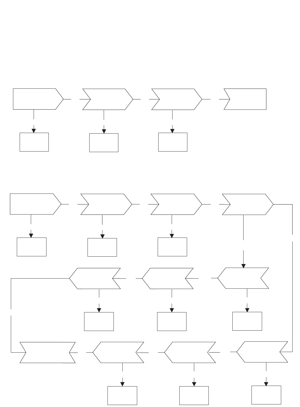
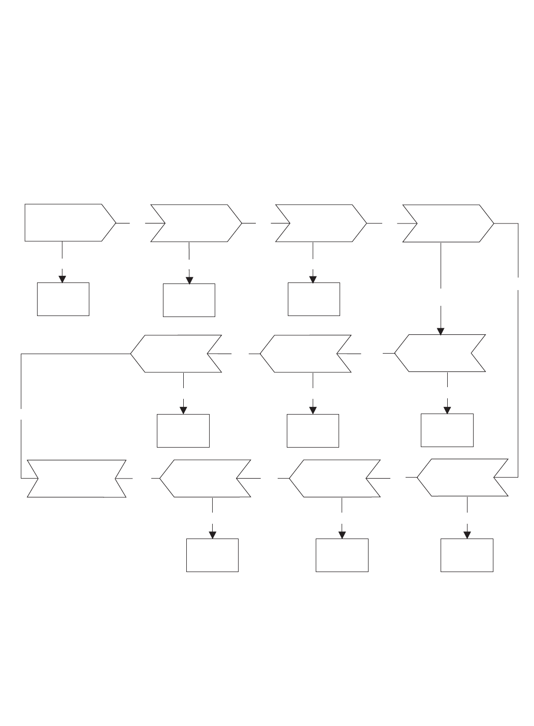
Troubleshooting
This fault–logic trouble shooting guide is a diagnostic aid in locating
transmission problems.
Match the transmission symptoms with the problem statements
and follow the action steps shown in the box diagrams. This will
give expedient aid in correcting minor problems eliminating
unnecessary machine down time.
Following the fault - logic diagrams are diagram action comments
of the action steps shown in the diagrams. Where applicable, the
comment number of the statement appears in the action block
of the diagrams.
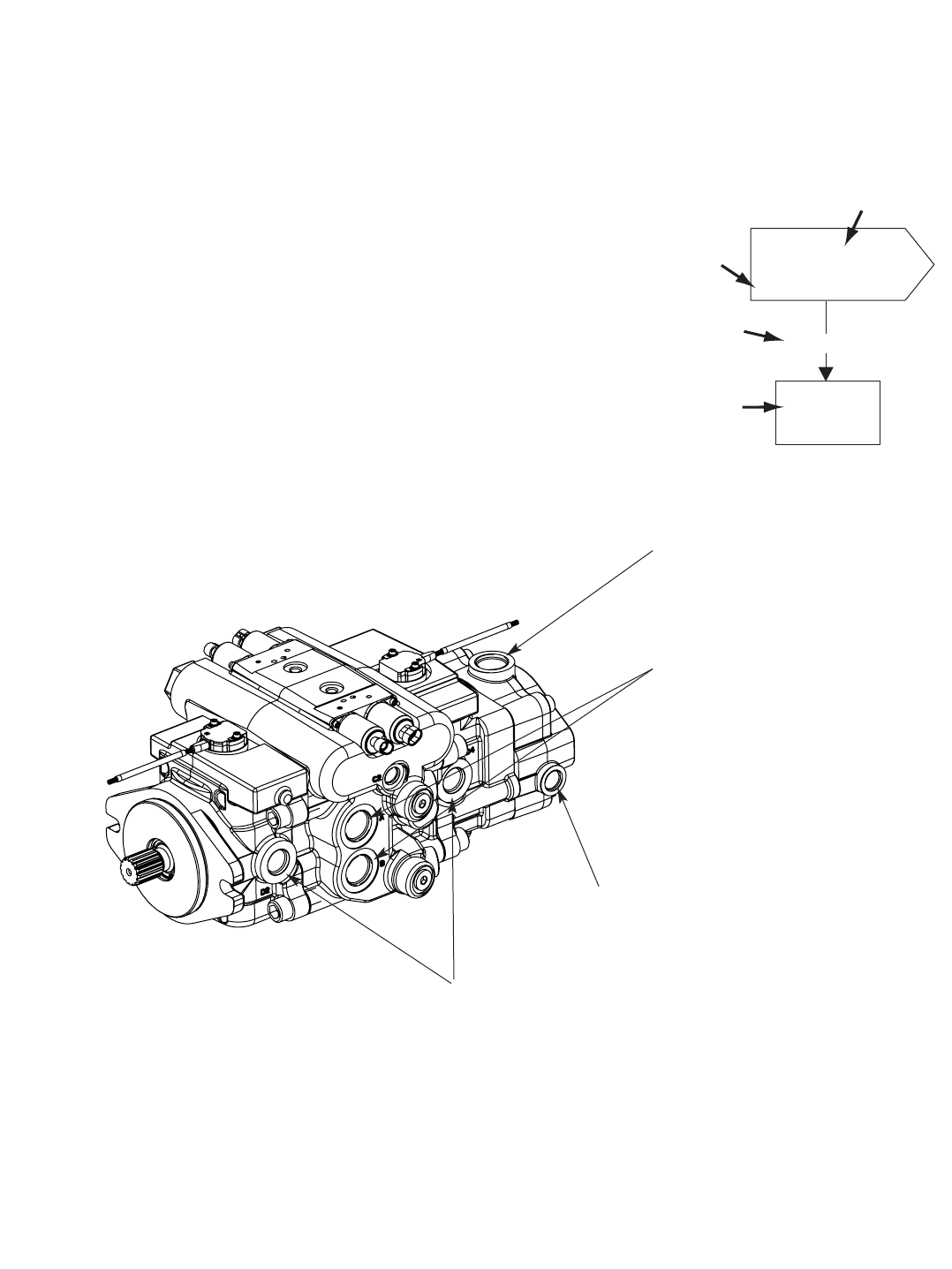
Recommended Gauge Locations
Fault - Logic Troubleshooting
Charge Pump Suction Port
Tee in line to check Inlet Vacuum
Pressure Ports
Tee in line to check
System Pressure
Auxilliary Port
check Charge Pressure
Drain Port
Tee in line to check
Case Pressure
Gauges Recommended
Inlet vacuum gauge: 2 bar to 1 bar [30 psi to 30 inHg]
System pressure gauge: 700 bar [10,000 psi]
Charge pressure gauge: 0 to 50 bar [0 to 600 psi]
Case pressure gauge: 0 to 25 bar [0 to 300 psi]
1
Inspect
?
Repair
or
Replace
Defective
Action
Step
Comment
Number
Decision
Solution
Symptom:
Explanatory
Diagram
40 EATON 350 Series Dual Path Mobile Pumps E-PUPI-TS006-E September 2007
Troubleshooting
Fault - Logic Troubleshooting
Inspect
Control Valve Inspect
Servo piston
Repair
or
Replace
Defective
Ok
Ok Ok
142
Replace
Pump
Symptom: Neutral Difficult or Impossible to Find
Inspect
External
Control Linkage
Repair
or
Replace
Defective
Defective
Repair
or
Replace
Inspect
Heat
Exchanger
Inspect Heat
Exchanger
Bypass Valve
(If used)
Repair
or
Replace
Defective
Ok
Ok Ok 765
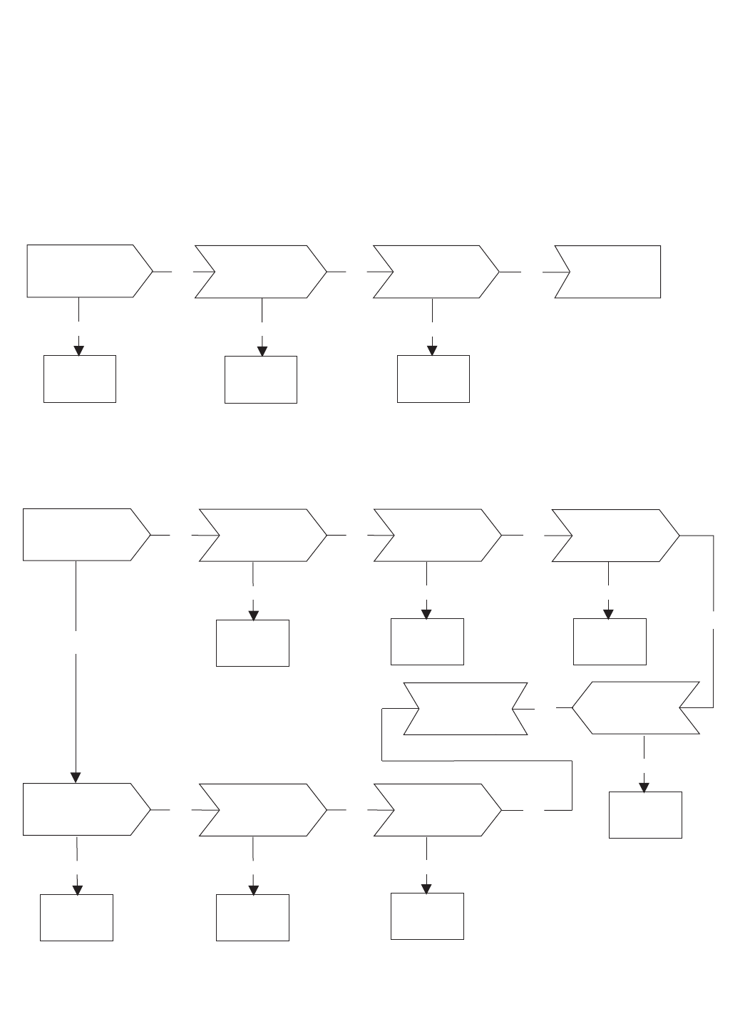
Symptom: System Operating Hot
Check
Oil Level in
Reservoir
Fill to
Proper
Level
Defective
Below Level
Repair
or
Replace
Check
System
Pressure
Reduce
System
Load
High
Ok 10
Inspect Charge
Relief Valve
Repair
or
Replace
Defective
Ok 12
Inspect
Charge
Pump
Repair
or
Replace
Defective
14
Inspect Motor
Repair
or
Replace
Defective
Ok 13
Inspect
Inlet
Screen or Filter
Replace
Clogged
Ok 9
Check
Charge
Pressure
11
Low Ok
Ok
Replace
Pump & Motor
Inspect
Bypass Valve
(If used)
Repair
or
Replace
Defective
Ok 8
41
EATON 350 Series Dual Path Mobile Pumps E-PUPI-TS006-E September 2007
Troubleshooting
Fault - Logic Troubleshooting
Repair
or
Replace
Repair
or
Replace
Inspect
System
Relief Valves
Repair
or
Replace
Defective
Ok Ok
Defective Defective
321
Symptom: Operates in One Direction Only
Inspect
External
Control LinkageInspect
Control Valve Ok Replace
Pump
Inspect
Control
Valve
Inspect
Bypass Valve
(If used)
Repair
or
Replace
Defective
Ok
Ok Ok 8211
Symptom: System Response Sluggish
Check
Charge
Pressure
Low
Defective
Repair
or
Replace
Inspect
Motor
Ok 13
Inspect
Servo
Piston
4
Ok
Replace
Pump & Motor
Repair
or
Replace
Defective
Repair
or
Replace
Defective
Inspect
Inlet
Screen or Filter
Inspect
Charge
Pump
Repair
or
Replace
Defective
Ok
Ok Ok
41921
Inspect
Charge Relief
Valve
Clogged
Replace
Defective
Repair
or
Replace
42 EATON 350 Series Dual Path Mobile Pumps E-PUPI-TS006-E September 2007
Troubleshooting
Fault - Logic Troubleshooting
Check External
Control
Linkage
Inspect
Bypass Valve
(If used)
Repair
or
Replace
Defective
Ok
Ok Ok
815
Symptom: System Will Not Operate in Either Direction
Check
Oil Level in
Reservoir
Fill to
Proper
Level
Defective
Below Level
Repair
or
Replace
Check
System
Pressure
Ok
11
Inspect Charge
Relief Valve
Repair
or
Replace
Defective
Ok
12
Inspect
Charge
Pump
Repair
or
Replace
Defective
14
Inspect
Inlet
Screen or Filter
Replace
Clogged
Ok
9
Check
Charge
Pressure
11
Low
Ok
Ok
Replace
Pump & Motor Inspect
Motor
Repair
or
Replace
Defective
13
Inspect
Control
Valve
Repair
or
Replace
Defective
Ok
2
Ok
Reduce
System
Load
High

43
EATON 350 Series Dual Path Mobile Pumps E-PUPI-TS006-E September 2007
Troubleshooting
Fault - Logic Troubleshooting
Diagram Action Step Comments
1 Inspect External Control Linkage for:
a. misadjusted or disconnected
b. binding, bent, or broken
2 Inspect Control Valve for:
a. plugged control orifice(s)
b. damaged mounting gasket
c. misadjusted, damaged or broken neutral return spring
d. broken control connector pin
e. faulty destroke valve (if used)
f. galled or stuck control spool
g. neutral detent or lockout switch misadjusted (if used)
3 Inspect System Relief Valves * for:
a. improper pressure relief setting
b. damaged or broken spring
c. valve held off seat
d. damaged valve seat
4 Inspect Servo Piston for:
a. misadjusted, damaged or broken neutral return
spring assembly
b. galled or stuck servo piston
c. damaged or missing o-ring and/or back-up ring
5 Check Oil Level in Reservoir:
a. consult owner/operators manual for the proper type
fluid and level
6 Inspect Heat Exchanger for:
a. obstructed air flow (air cooled)
b. obstructed water flow (water cooled)
c. improper plumbing (inlet to outlet)
d. obstructed fluid flow
7 Inspect Heat Exchanger Bypass Valve for:
a. improper pressure adjustment
b. stuck or broken valve
8 Inspect Bypass Valve for: (if used)
a. held in a partial or full open position
9 Inspect Inlet Screen or Filter for:
a. plugged or clogged screen or filter element
b. obstructed inlet or outlet
c. open inlet to charge pump
10 Check System Pressure:
a. See figure 3-1 for location of pressure gauge
installation
b. consult owner/operators manual for maximum system
relief valve settings
11 Check Charge Pressure:
a. See figure 3-1 for location of charge pressure gauge
installation
b. consult owner/operators manual for maximum charge
relief valve settings
12 Inspect Charge Relief Valve for:
a. improper charge relief pressure setting *
b. damaged or broken spring
c. poppet valve held off seat
13 Inspect Motor for:
a. consult owner/operator manual for motor operation
and trouble shooting
14 Inspect Charge Pump for:
a. broken or missing drive key
b. damaged or missing o-ring
c. excessive gerotor clearance
d. galled or broken gerotor set*
System/Charge Relief Valve Pressure Settings
Inlet Vacuum 0,203 bar [6 inHg] max.
Case Pressure 1,7 bar [25 PSI] maximum
Charge Pressure 17,24 to 20,68 bar
[250 to 300 PSI]*
System Pressure 345 bar [5000 PSI] maximum**
207 bar [3000 PSI] continuous
*Min: 13.8–17.2 Bar [200–250 psi], Max: 27.6–31 Bar [400–450 psi]
**380 Bar [5500 psi] Max, 276 Bar [4000 psi] Continuous
The high pressure relief valves are all factory preset and cannot
be readjusted.
The pressure setting is stamped on each valve with a three digit
number. To identify, multiply the noted number by 10 to get the
valves pressure setting.
Example: 10 x 500 = [5000 PSI] 345 bar

44 EATON 350 Series Dual Path Mobile Pumps E-PUPI-TS006-E September 2007
Start-Up
Procedure
When initially starting a new or
a rebuilt transmission system, it
is extremely important that the
start-up procedure be followed.
It prevents the chance of dam-
aging the unit which might
occur if the system was not
properly purged of air before
start-up.
1. After the transmission com-
ponents have been properly
installed, fill the servo pump
housing at least half full with
filtered system oil. Connect
all hydraulic lines and check
to be sure they are tight.
2. Install and adjust all control
linkage.
3. Fill the reservoir with an
approved oil that has been fil-
tered through a 10 micron fil-
ter. Refer to Eaton Technical
Data sheet number 3-401
titled Hydraulic Fluid
Recommendations.
4. Gasoline or L.P. engines:
remove the coil wire and turn
the engine over for 15 sec-
onds. Diesel engines: shut
off the fuel flow to the injec-
tors and turn the engine over
for 15 seconds.
5. Replace the coil wire or
return the fuel flow to the
injectors. Place the transmis-
sion unit in the neutral posi-
tion, start the engine and run
it at a low idle. The charge
pump should immediately
pick up oil and fill the sys-
tem. If there is no indication
of fill in 30 seconds, stop
engine and determine the
cause.
6. After the system starts to
show signs of fill, slowly
move pump swashplate to a
slight cam angle. Continue to
operate system slowly with
no load on motors until sys-
tem responds fully.
7. Check fluid level in the reser-
voir and refill if necessary to
the proper level with an
approved filtered oil.
8. Check all line connections for
leaks and tighten if necessary.
9. The machine is now ready to
be put into operation.
10. Frequent filter changes are
recommended for the first
two changes after placing
the machine back into opera-
tion. Change the first filter in
3-5 hours and the second at
approximately 50 hours.
Routinely scheduled filter
changes are recommended
for maximum life of the
hydraulic system.

45
EATON 350 Series Dual Path Mobile Pumps E-PUPI-TS006-E September 2007
How to Order
Single Pump - Product Number:
Tandem Pumps - Product Number:
A B C
A B C
Dual Pump - Product Number:
A B C
552AK A00001
559AK A00001
558AK A00001
