Eaton Electrical D77A Users Manual
D77A to the manual 6409331c-311d-438d-b1ed-3f334774bdf9
2015-02-06
: Eaton-Electrical Eaton-Electrical-D77A-Users-Manual-537239 eaton-electrical-d77a-users-manual-537239 eaton-electrical pdf
Open the PDF directly: View PDF ![]() .
.
Page Count: 62
- Table of Contents
- Safety
- Introduction
- Specifications
- Theory of Operation
- Installation
- Troubleshooting and Maintenance
- Appendix A
- IT. Publications and Support
MN05002001E For more information visit: www.EatonElectrical.com
Intelligent Technologies (IT.)
D77A I/O Module Products
Installation and User Manual
November 2006
Supersedes October 2005
Part Numbers
D77A-DI8 D77A-RQ8
D77A-DI16 D77A-RQ16
D77A-DQ8 D77A-DI8DQ8
D77A-DQ16 D77A-DI8RQ8
D77A-AI8 D77A-AI8AQ8
D77A-AI16 D77A-AI8RQ8
D77A-AQ8 D77A-NI4
D77A-AQ16 D77A-NQ2

Intelligent Technologies (IT.) D77A I/O Module Products
MN05002001E For more information visit: www.EatonElectrical.com i
Important Notice — Please Read
The product discussed in this literature is subject to terms and conditions outlined in Eaton Electrical Inc. selling policies. The sole
source governing the rights and remedies of any purchaser of this equipment is the relevant Eaton Electrical Inc. selling policy.
NO WARRANTIES, EXPRESS OR IMPLIED, INCLUDING WARRANTIES OF FITNESS FOR A PARTICULAR PURPOSE OR
MERCHANTABILITY, OR WARRANTIES ARISING FROM COURSE OF DEALING OR USAGE OF TRADE, ARE MADE REGARDING THE
INFORMATION, RECOMMENDATIONS AND DESCRIPTIONS CONTAINED HEREIN. In no event will Eaton Electrical Inc. be responsible
to the purchaser or user in contract, in tort (including negligence), strict liability or otherwise for any special, indirect, incidental or
consequential damage or loss whatsoever, including but not limited to damage or loss of use of equipment, plant or power system,
cost of capital, loss of power, additional expenses in the use of existing power facilities, or claims against the purchaser or user by its
customers resulting from the use of the information, recommendations and descriptions contained herein.
The information contained in this manual is subject to change without notice.
Cover Photo: Eaton’s Cutler-Hammer® Intelligent Technologies (IT.) D77A I/O Module Products

ii For more information visit: www.EatonElectrical.com MN05002001E
Intelligent Technologies (IT.) D77A I/O Module Products
Table of Contents
LIST OF FIGURES . . . . . . . . . . . . . . . . . . . . . . . . . . . . . . . . . . . . . . . . . . . . . . . . . . . . . . . . . . . . . . . . . . . . . . . . . . . . . . . . . . . . . . iii
LIST OF TABLES . . . . . . . . . . . . . . . . . . . . . . . . . . . . . . . . . . . . . . . . . . . . . . . . . . . . . . . . . . . . . . . . . . . . . . . . . . . . . . . . . . . . . . . iii
SAFETY . . . . . . . . . . . . . . . . . . . . . . . . . . . . . . . . . . . . . . . . . . . . . . . . . . . . . . . . . . . . . . . . . . . . . . . . . . . . . . . . . . . . . . . . . . . . . . .v
Definitions and Symbols . . . . . . . . . . . . . . . . . . . . . . . . . . . . . . . . . . . . . . . . . . . . . . . . . . . . . . . . . . . . . . . . . . . . . . . . . . . . . .v
Hazardous High Voltage . . . . . . . . . . . . . . . . . . . . . . . . . . . . . . . . . . . . . . . . . . . . . . . . . . . . . . . . . . . . . . . . . . . . . . . . . . . . . . .v
General Safety . . . . . . . . . . . . . . . . . . . . . . . . . . . . . . . . . . . . . . . . . . . . . . . . . . . . . . . . . . . . . . . . . . . . . . . . . . . . . . . . . . . . . vi
INTRODUCTION . . . . . . . . . . . . . . . . . . . . . . . . . . . . . . . . . . . . . . . . . . . . . . . . . . . . . . . . . . . . . . . . . . . . . . . . . . . . . . . . . . . . . . . 1
Description . . . . . . . . . . . . . . . . . . . . . . . . . . . . . . . . . . . . . . . . . . . . . . . . . . . . . . . . . . . . . . . . . . . . . . . . . . . . . . . . . . . . . . . . 1
Component Characteristics . . . . . . . . . . . . . . . . . . . . . . . . . . . . . . . . . . . . . . . . . . . . . . . . . . . . . . . . . . . . . . . . . . . . . . . . . . . 1
Catalog Numbering System . . . . . . . . . . . . . . . . . . . . . . . . . . . . . . . . . . . . . . . . . . . . . . . . . . . . . . . . . . . . . . . . . . . . . . . . . . . 3
SPECIFICATIONS . . . . . . . . . . . . . . . . . . . . . . . . . . . . . . . . . . . . . . . . . . . . . . . . . . . . . . . . . . . . . . . . . . . . . . . . . . . . . . . . . . . . . . 4
Physical Description . . . . . . . . . . . . . . . . . . . . . . . . . . . . . . . . . . . . . . . . . . . . . . . . . . . . . . . . . . . . . . . . . . . . . . . . . . . . . . . . . 4
Dimensional Data . . . . . . . . . . . . . . . . . . . . . . . . . . . . . . . . . . . . . . . . . . . . . . . . . . . . . . . . . . . . . . . . . . . . . . . . . . . . . . . . . . . 5
Power Requirements . . . . . . . . . . . . . . . . . . . . . . . . . . . . . . . . . . . . . . . . . . . . . . . . . . . . . . . . . . . . . . . . . . . . . . . . . . . . . . . . 5
Surge Suppression . . . . . . . . . . . . . . . . . . . . . . . . . . . . . . . . . . . . . . . . . . . . . . . . . . . . . . . . . . . . . . . . . . . . . . . . . . . . . . . . . . 5
Environmental Specifications . . . . . . . . . . . . . . . . . . . . . . . . . . . . . . . . . . . . . . . . . . . . . . . . . . . . . . . . . . . . . . . . . . . . . . . . . . 6
Device Default I/O Data . . . . . . . . . . . . . . . . . . . . . . . . . . . . . . . . . . . . . . . . . . . . . . . . . . . . . . . . . . . . . . . . . . . . . . . . . . . . . . 6
I/O Module Summary. . . . . . . . . . . . . . . . . . . . . . . . . . . . . . . . . . . . . . . . . . . . . . . . . . . . . . . . . . . . . . . . . . . . . . . . . . . . . . . . 7
Input Specifications . . . . . . . . . . . . . . . . . . . . . . . . . . . . . . . . . . . . . . . . . . . . . . . . . . . . . . . . . . . . . . . . . . . . . . . . . . . . . . . . . 8
Output Specifications. . . . . . . . . . . . . . . . . . . . . . . . . . . . . . . . . . . . . . . . . . . . . . . . . . . . . . . . . . . . . . . . . . . . . . . . . . . . . . . 13
Special I/O Specifications. . . . . . . . . . . . . . . . . . . . . . . . . . . . . . . . . . . . . . . . . . . . . . . . . . . . . . . . . . . . . . . . . . . . . . . . . . . . 18
THEORY OF OPERATION . . . . . . . . . . . . . . . . . . . . . . . . . . . . . . . . . . . . . . . . . . . . . . . . . . . . . . . . . . . . . . . . . . . . . . . . . . . . . . . 22
Out-of-box Default Operation. . . . . . . . . . . . . . . . . . . . . . . . . . . . . . . . . . . . . . . . . . . . . . . . . . . . . . . . . . . . . . . . . . . . . . . . . 22
Typical Application . . . . . . . . . . . . . . . . . . . . . . . . . . . . . . . . . . . . . . . . . . . . . . . . . . . . . . . . . . . . . . . . . . . . . . . . . . . . . . . . . 22
I/O Function . . . . . . . . . . . . . . . . . . . . . . . . . . . . . . . . . . . . . . . . . . . . . . . . . . . . . . . . . . . . . . . . . . . . . . . . . . . . . . . . . . . . . . 23
INSTALLATION. . . . . . . . . . . . . . . . . . . . . . . . . . . . . . . . . . . . . . . . . . . . . . . . . . . . . . . . . . . . . . . . . . . . . . . . . . . . . . . . . . . . . . . 27
Setting Group ID . . . . . . . . . . . . . . . . . . . . . . . . . . . . . . . . . . . . . . . . . . . . . . . . . . . . . . . . . . . . . . . . . . . . . . . . . . . . . . . . . . 27
QCPort Connections . . . . . . . . . . . . . . . . . . . . . . . . . . . . . . . . . . . . . . . . . . . . . . . . . . . . . . . . . . . . . . . . . . . . . . . . . . . . . . . 32
Configuration . . . . . . . . . . . . . . . . . . . . . . . . . . . . . . . . . . . . . . . . . . . . . . . . . . . . . . . . . . . . . . . . . . . . . . . . . . . . . . . . . . . . . 34
Field Wiring . . . . . . . . . . . . . . . . . . . . . . . . . . . . . . . . . . . . . . . . . . . . . . . . . . . . . . . . . . . . . . . . . . . . . . . . . . . . . . . . . . . . . . 35
TROUBLESHOOTING AND MAINTENANCE . . . . . . . . . . . . . . . . . . . . . . . . . . . . . . . . . . . . . . . . . . . . . . . . . . . . . . . . . . . . . . . 45
Status LED . . . . . . . . . . . . . . . . . . . . . . . . . . . . . . . . . . . . . . . . . . . . . . . . . . . . . . . . . . . . . . . . . . . . . . . . . . . . . . . . . . . . . . . 45
Fault Codes . . . . . . . . . . . . . . . . . . . . . . . . . . . . . . . . . . . . . . . . . . . . . . . . . . . . . . . . . . . . . . . . . . . . . . . . . . . . . . . . . . . . . . 45
Troubleshooting . . . . . . . . . . . . . . . . . . . . . . . . . . . . . . . . . . . . . . . . . . . . . . . . . . . . . . . . . . . . . . . . . . . . . . . . . . . . . . . . . . . 46
Renewal Parts . . . . . . . . . . . . . . . . . . . . . . . . . . . . . . . . . . . . . . . . . . . . . . . . . . . . . . . . . . . . . . . . . . . . . . . . . . . . . . . . . . . . 46
Communication Troubleshooting Hints . . . . . . . . . . . . . . . . . . . . . . . . . . . . . . . . . . . . . . . . . . . . . . . . . . . . . . . . . . . . . . . . . 46
APPENDIX A . . . . . . . . . . . . . . . . . . . . . . . . . . . . . . . . . . . . . . . . . . . . . . . . . . . . . . . . . . . . . . . . . . . . . . . . . . . . . . . . . . . . . . . . . 48
Data Parameters . . . . . . . . . . . . . . . . . . . . . . . . . . . . . . . . . . . . . . . . . . . . . . . . . . . . . . . . . . . . . . . . . . . . . . . . . . . . . . . . . . 48
Configuration Parameters . . . . . . . . . . . . . . . . . . . . . . . . . . . . . . . . . . . . . . . . . . . . . . . . . . . . . . . . . . . . . . . . . . . . . . . . . . . 50
Analog Data Registers . . . . . . . . . . . . . . . . . . . . . . . . . . . . . . . . . . . . . . . . . . . . . . . . . . . . . . . . . . . . . . . . . . . . . . . . . . . . . . 53
IT. PUBLICATIONS AND SUPPORT . . . . . . . . . . . . . . . . . . . . . . . . . . . . . . . . . . . . . . . . . . . . . . . . . . . . . . . . . . . . . . . . . . . . . . 53
Publications . . . . . . . . . . . . . . . . . . . . . . . . . . . . . . . . . . . . . . . . . . . . . . . . . . . . . . . . . . . . . . . . . . . . . . . . . . . . . . . . . . . . . . 53

Intelligent Technologies (IT.) D77A I/O Module Products
MN05002001E For more information visit: www.EatonElectrical.com iii
List of Figures
Figure 1: I/O Module Component Location . . . . . . . . . . . . . . . . . . . . . . . . . . . . . . . . . . . . . . . . . . . . . . . . . . . . . . . . . . . . . . . . . . . 4
Figure 2: Module Physical Dimensions, mm [in] . . . . . . . . . . . . . . . . . . . . . . . . . . . . . . . . . . . . . . . . . . . . . . . . . . . . . . . . . . . . . . . 5
Figure 3: AC Input Module Diagrams . . . . . . . . . . . . . . . . . . . . . . . . . . . . . . . . . . . . . . . . . . . . . . . . . . . . . . . . . . . . . . . . . . . . . . . . 8
Figure 4: DC Input Module Diagrams . . . . . . . . . . . . . . . . . . . . . . . . . . . . . . . . . . . . . . . . . . . . . . . . . . . . . . . . . . . . . . . . . . . . . . . . 9
Figure 5: D77A-NI4 Analog Input Module Diagrams. . . . . . . . . . . . . . . . . . . . . . . . . . . . . . . . . . . . . . . . . . . . . . . . . . . . . . . . . . . . 11
Figure 6: Analog Input Curves . . . . . . . . . . . . . . . . . . . . . . . . . . . . . . . . . . . . . . . . . . . . . . . . . . . . . . . . . . . . . . . . . . . . . . . . . . . . 12
Figure 7: AC Output Module Diagrams . . . . . . . . . . . . . . . . . . . . . . . . . . . . . . . . . . . . . . . . . . . . . . . . . . . . . . . . . . . . . . . . . . . . . 13
Figure 8: DC Output Module Diagrams . . . . . . . . . . . . . . . . . . . . . . . . . . . . . . . . . . . . . . . . . . . . . . . . . . . . . . . . . . . . . . . . . . . . . 14
Figure 9: Relay Output Module Diagrams . . . . . . . . . . . . . . . . . . . . . . . . . . . . . . . . . . . . . . . . . . . . . . . . . . . . . . . . . . . . . . . . . . . 15
Figure 10: D77A-NQ2 Combination Module Diagrams. . . . . . . . . . . . . . . . . . . . . . . . . . . . . . . . . . . . . . . . . . . . . . . . . . . . . . . . . . 16
Figure 11: Analog Output Curves for 14 Bit Resolution . . . . . . . . . . . . . . . . . . . . . . . . . . . . . . . . . . . . . . . . . . . . . . . . . . . . . . . . . 17
Figure 12: D77A-DI8DQ8 Combination Module Diagrams . . . . . . . . . . . . . . . . . . . . . . . . . . . . . . . . . . . . . . . . . . . . . . . . . . . . . . . 18
Figure 13: D77A-DI8RQ8 Combination Module Diagrams . . . . . . . . . . . . . . . . . . . . . . . . . . . . . . . . . . . . . . . . . . . . . . . . . . . . . . . 19
Figure 14: D77A-AI8AQ8 Combination Module Diagrams . . . . . . . . . . . . . . . . . . . . . . . . . . . . . . . . . . . . . . . . . . . . . . . . . . . . . . . 20
Figure 15: D77A-AI8RQ8 Combination Module Diagrams . . . . . . . . . . . . . . . . . . . . . . . . . . . . . . . . . . . . . . . . . . . . . . . . . . . . . . . 21
Figure 16: Panel Layout: Adapter, I/O and QSNAP. . . . . . . . . . . . . . . . . . . . . . . . . . . . . . . . . . . . . . . . . . . . . . . . . . . . . . . . . . . . . 22
Figure 17: Discrete Input Module Operation . . . . . . . . . . . . . . . . . . . . . . . . . . . . . . . . . . . . . . . . . . . . . . . . . . . . . . . . . . . . . . . . . 23
Figure 18: Discrete Output Module Operation . . . . . . . . . . . . . . . . . . . . . . . . . . . . . . . . . . . . . . . . . . . . . . . . . . . . . . . . . . . . . . . . 23
Figure 19: Discrete Combination Module Operation . . . . . . . . . . . . . . . . . . . . . . . . . . . . . . . . . . . . . . . . . . . . . . . . . . . . . . . . . . . 24
Figure 20: Analog Input Module Operation. . . . . . . . . . . . . . . . . . . . . . . . . . . . . . . . . . . . . . . . . . . . . . . . . . . . . . . . . . . . . . . . . . . 25
Figure 21: Analog Output Module Operation . . . . . . . . . . . . . . . . . . . . . . . . . . . . . . . . . . . . . . . . . . . . . . . . . . . . . . . . . . . . . . . . . 26
Figure 22: Group ID Switch . . . . . . . . . . . . . . . . . . . . . . . . . . . . . . . . . . . . . . . . . . . . . . . . . . . . . . . . . . . . . . . . . . . . . . . . . . . . . . 27
Figure 23: Removable Terminal Locking Tabs . . . . . . . . . . . . . . . . . . . . . . . . . . . . . . . . . . . . . . . . . . . . . . . . . . . . . . . . . . . . . . . . 28
Figure 24: Unlock DIN Rail Locking Tab . . . . . . . . . . . . . . . . . . . . . . . . . . . . . . . . . . . . . . . . . . . . . . . . . . . . . . . . . . . . . . . . . . . . . 28
Figure 25: Lock DIN Rail Locking Tab . . . . . . . . . . . . . . . . . . . . . . . . . . . . . . . . . . . . . . . . . . . . . . . . . . . . . . . . . . . . . . . . . . . . . . . 29
Figure 26: Removable Terminal Locking Tab . . . . . . . . . . . . . . . . . . . . . . . . . . . . . . . . . . . . . . . . . . . . . . . . . . . . . . . . . . . . . . . . . 29
Figure 27: Removable Terminal Locking Tabs . . . . . . . . . . . . . . . . . . . . . . . . . . . . . . . . . . . . . . . . . . . . . . . . . . . . . . . . . . . . . . . . 30
Figure 28: Unlock DIN Rail Locking Tab . . . . . . . . . . . . . . . . . . . . . . . . . . . . . . . . . . . . . . . . . . . . . . . . . . . . . . . . . . . . . . . . . . . . . 30
Figure 29: Lock DIN Rail Locking Tab . . . . . . . . . . . . . . . . . . . . . . . . . . . . . . . . . . . . . . . . . . . . . . . . . . . . . . . . . . . . . . . . . . . . . . . 31
Figure 30: Removable Terminal Locking Tab . . . . . . . . . . . . . . . . . . . . . . . . . . . . . . . . . . . . . . . . . . . . . . . . . . . . . . . . . . . . . . . . . 31
Figure 31: QCPort Backplane Interconnect . . . . . . . . . . . . . . . . . . . . . . . . . . . . . . . . . . . . . . . . . . . . . . . . . . . . . . . . . . . . . . . . . . 32
Figure 32: QCPort Interconnect Backplane Connectors . . . . . . . . . . . . . . . . . . . . . . . . . . . . . . . . . . . . . . . . . . . . . . . . . . . . . . . . . 32
Figure 33: QCPort Connector . . . . . . . . . . . . . . . . . . . . . . . . . . . . . . . . . . . . . . . . . . . . . . . . . . . . . . . . . . . . . . . . . . . . . . . . . . . . . 33
Figure 34: I/O Property Page . . . . . . . . . . . . . . . . . . . . . . . . . . . . . . . . . . . . . . . . . . . . . . . . . . . . . . . . . . . . . . . . . . . . . . . . . . . . . 34
Figure 35: AC Input Wiring . . . . . . . . . . . . . . . . . . . . . . . . . . . . . . . . . . . . . . . . . . . . . . . . . . . . . . . . . . . . . . . . . . . . . . . . . . . . . . . 37
Figure 36: DC Input Wiring . . . . . . . . . . . . . . . . . . . . . . . . . . . . . . . . . . . . . . . . . . . . . . . . . . . . . . . . . . . . . . . . . . . . . . . . . . . . . . . 38
Figure 37: Analog Input Wiring . . . . . . . . . . . . . . . . . . . . . . . . . . . . . . . . . . . . . . . . . . . . . . . . . . . . . . . . . . . . . . . . . . . . . . . . . . . . 39
Figure 38: AC Output Wiring . . . . . . . . . . . . . . . . . . . . . . . . . . . . . . . . . . . . . . . . . . . . . . . . . . . . . . . . . . . . . . . . . . . . . . . . . . . . . 40
Figure 39: DC Output Wiring . . . . . . . . . . . . . . . . . . . . . . . . . . . . . . . . . . . . . . . . . . . . . . . . . . . . . . . . . . . . . . . . . . . . . . . . . . . . . 41
Figure 40: Relay Output Wiring . . . . . . . . . . . . . . . . . . . . . . . . . . . . . . . . . . . . . . . . . . . . . . . . . . . . . . . . . . . . . . . . . . . . . . . . . . . 42
Figure 41: Analog Output Wiring . . . . . . . . . . . . . . . . . . . . . . . . . . . . . . . . . . . . . . . . . . . . . . . . . . . . . . . . . . . . . . . . . . . . . . . . . . 43
Figure 42: Combination I/O Wiring . . . . . . . . . . . . . . . . . . . . . . . . . . . . . . . . . . . . . . . . . . . . . . . . . . . . . . . . . . . . . . . . . . . . . . . . . 44
List of Tables
Table 1: Approvals/Certifications . . . . . . . . . . . . . . . . . . . . . . . . . . . . . . . . . . . . . . . . . . . . . . . . . . . . . . . . . . . . . . . . . . . . . . . . . . . 2
Table 2: Catalog Numbering System . . . . . . . . . . . . . . . . . . . . . . . . . . . . . . . . . . . . . . . . . . . . . . . . . . . . . . . . . . . . . . . . . . . . . . . . 3
Table 3: Environmental Ratings . . . . . . . . . . . . . . . . . . . . . . . . . . . . . . . . . . . . . . . . . . . . . . . . . . . . . . . . . . . . . . . . . . . . . . . . . . . . 6
Table 4: 8 Point Discrete Input Module (Produced) . . . . . . . . . . . . . . . . . . . . . . . . . . . . . . . . . . . . . . . . . . . . . . . . . . . . . . . . . . . . . 6
Table 5: 8 Point Discrete Output Module (Consumed). . . . . . . . . . . . . . . . . . . . . . . . . . . . . . . . . . . . . . . . . . . . . . . . . . . . . . . . . . . 6
Table 6: 16 Point Discrete Input Module (Produced) . . . . . . . . . . . . . . . . . . . . . . . . . . . . . . . . . . . . . . . . . . . . . . . . . . . . . . . . . . . . 6
Table 7: 16 Point Discrete Output Module (Consumed). . . . . . . . . . . . . . . . . . . . . . . . . . . . . . . . . . . . . . . . . . . . . . . . . . . . . . . . . . 6
Table 8: 16 Point Discrete Combination Module (Produced) . . . . . . . . . . . . . . . . . . . . . . . . . . . . . . . . . . . . . . . . . . . . . . . . . . . . . . 6
Table 9: 16 Point Discrete Combination Module (Consumed) . . . . . . . . . . . . . . . . . . . . . . . . . . . . . . . . . . . . . . . . . . . . . . . . . . . . . 6
Table 10: 4 Channel Analog Input Module (Produced) . . . . . . . . . . . . . . . . . . . . . . . . . . . . . . . . . . . . . . . . . . . . . . . . . . . . . . . . . . . 6
Table 11: 2 Channel Analog Output Module (Consumed) . . . . . . . . . . . . . . . . . . . . . . . . . . . . . . . . . . . . . . . . . . . . . . . . . . . . . . . . 7
Table 12: I/O Devices . . . . . . . . . . . . . . . . . . . . . . . . . . . . . . . . . . . . . . . . . . . . . . . . . . . . . . . . . . . . . . . . . . . . . . . . . . . . . . . . . . . . 7
Table 13: AC Input Module Specifications . . . . . . . . . . . . . . . . . . . . . . . . . . . . . . . . . . . . . . . . . . . . . . . . . . . . . . . . . . . . . . . . . . . . 8
Table 14: DC Input Module Specifications . . . . . . . . . . . . . . . . . . . . . . . . . . . . . . . . . . . . . . . . . . . . . . . . . . . . . . . . . . . . . . . . . . . . 9
Table 15: D77A-NI4 Analog Input Module Specifications . . . . . . . . . . . . . . . . . . . . . . . . . . . . . . . . . . . . . . . . . . . . . . . . . . . . . . . . 10
Table 16: AC Output Module Specifications. . . . . . . . . . . . . . . . . . . . . . . . . . . . . . . . . . . . . . . . . . . . . . . . . . . . . . . . . . . . . . . . . . 13
Table 17: DC Output Module Specifications. . . . . . . . . . . . . . . . . . . . . . . . . . . . . . . . . . . . . . . . . . . . . . . . . . . . . . . . . . . . . . . . . . 14

iv For more information visit: www.EatonElectrical.com MN05002001E
Intelligent Technologies (IT.) D77A I/O Module Products
Table 18: Relay Output Module Specifications. . . . . . . . . . . . . . . . . . . . . . . . . . . . . . . . . . . . . . . . . . . . . . . . . . . . . . . . . . . . . . . . 15
Table 19: D77A-NQ2 Analog Output Module Specifications . . . . . . . . . . . . . . . . . . . . . . . . . . . . . . . . . . . . . . . . . . . . . . . . . . . . . 16
Table 20: D77A-DI8DQ8 Combination Module Specifications . . . . . . . . . . . . . . . . . . . . . . . . . . . . . . . . . . . . . . . . . . . . . . . . . . . . 18
Table 21: D77A-DI8RQ8 Combination Module Specifications . . . . . . . . . . . . . . . . . . . . . . . . . . . . . . . . . . . . . . . . . . . . . . . . . . . . 19
Table 22: D77A-AI8AQ8 Combination Module Specifications . . . . . . . . . . . . . . . . . . . . . . . . . . . . . . . . . . . . . . . . . . . . . . . . . . . . 20
Table 23: D77A-AI8RQ8 Combination Module Specifications . . . . . . . . . . . . . . . . . . . . . . . . . . . . . . . . . . . . . . . . . . . . . . . . . . . . 21
Table 24: Analog Input Signal Delays . . . . . . . . . . . . . . . . . . . . . . . . . . . . . . . . . . . . . . . . . . . . . . . . . . . . . . . . . . . . . . . . . . . . . . . 25
Table 25: Symbol Definitions . . . . . . . . . . . . . . . . . . . . . . . . . . . . . . . . . . . . . . . . . . . . . . . . . . . . . . . . . . . . . . . . . . . . . . . . . . . . . 35
Table 26: Status LED . . . . . . . . . . . . . . . . . . . . . . . . . . . . . . . . . . . . . . . . . . . . . . . . . . . . . . . . . . . . . . . . . . . . . . . . . . . . . . . . . . . 45
Table 27: Analog 10 Fault Codes . . . . . . . . . . . . . . . . . . . . . . . . . . . . . . . . . . . . . . . . . . . . . . . . . . . . . . . . . . . . . . . . . . . . . . . . . . 45
Table 28: Troubleshooting . . . . . . . . . . . . . . . . . . . . . . . . . . . . . . . . . . . . . . . . . . . . . . . . . . . . . . . . . . . . . . . . . . . . . . . . . . . . . . . 46
Table 29: I/O Module Renewal Parts . . . . . . . . . . . . . . . . . . . . . . . . . . . . . . . . . . . . . . . . . . . . . . . . . . . . . . . . . . . . . . . . . . . . . . . 46
Table 30: Explanation of LED Duty Cycle States . . . . . . . . . . . . . . . . . . . . . . . . . . . . . . . . . . . . . . . . . . . . . . . . . . . . . . . . . . . . . . 46
Table 31: Status LED . . . . . . . . . . . . . . . . . . . . . . . . . . . . . . . . . . . . . . . . . . . . . . . . . . . . . . . . . . . . . . . . . . . . . . . . . . . . . . . . . . . 47
Table 32: Communication Hints . . . . . . . . . . . . . . . . . . . . . . . . . . . . . . . . . . . . . . . . . . . . . . . . . . . . . . . . . . . . . . . . . . . . . . . . . . . 47
Table 33: 0x0001 (1) Production Data. . . . . . . . . . . . . . . . . . . . . . . . . . . . . . . . . . . . . . . . . . . . . . . . . . . . . . . . . . . . . . . . . . . . . . . 48
Table 34: 0x0002 (2) Consumption Data. . . . . . . . . . . . . . . . . . . . . . . . . . . . . . . . . . . . . . . . . . . . . . . . . . . . . . . . . . . . . . . . . . . . . 48
Table 35: 0x0003 (3) QCPort Status . . . . . . . . . . . . . . . . . . . . . . . . . . . . . . . . . . . . . . . . . . . . . . . . . . . . . . . . . . . . . . . . . . . . . . . . 48
Table 36: 0x0004 (4) Application Status (Available in I/O As Control Elements). . . . . . . . . . . . . . . . . . . . . . . . . . . . . . . . . . . . . . . 48
Table 37: 0x0005 (5) Discrete Data Input (Available in I/O As Control Elements). . . . . . . . . . . . . . . . . . . . . . . . . . . . . . . . . . . . . . 48
Table 38: 0x0006 (6) Discrete Data Output (Available in I/O As Control Elements) . . . . . . . . . . . . . . . . . . . . . . . . . . . . . . . . . . . . 48
Table 39: 0x006B (107) Analog Input Status (Available in I/O As Control Elements) . . . . . . . . . . . . . . . . . . . . . . . . . . . . . . . . . . . 48
Table 40: 0x006C (108) Analog Output Status (Available in I/O As Control Elements). . . . . . . . . . . . . . . . . . . . . . . . . . . . . . . . . . 49
Table 41: 0x006F (111) 16 bit Signed Analog Input Data (Available in I/O As Control Elements) . . . . . . . . . . . . . . . . . . . . . . . . . . 49
Table 42: 0x0070 (112) 16 bit Signed Analog Output Data (Available in I/O As Control Elements) . . . . . . . . . . . . . . . . . . . . . . . . 49
Table 43: 0x8001 (32769) Device Identity . . . . . . . . . . . . . . . . . . . . . . . . . . . . . . . . . . . . . . . . . . . . . . . . . . . . . . . . . . . . . . . . . . . 50
Table 44: 0x8002 (32770) Configuration CRC. . . . . . . . . . . . . . . . . . . . . . . . . . . . . . . . . . . . . . . . . . . . . . . . . . . . . . . . . . . . . . . . . 50
Table 45: 0x8003 (32771) Node ID . . . . . . . . . . . . . . . . . . . . . . . . . . . . . . . . . . . . . . . . . . . . . . . . . . . . . . . . . . . . . . . . . . . . . . . . . 50
Table 46: 0x8004 (32772) Operating Mode . . . . . . . . . . . . . . . . . . . . . . . . . . . . . . . . . . . . . . . . . . . . . . . . . . . . . . . . . . . . . . . . . . 50
Table 47: 0x8005 (32773) QCPort Baud Rate . . . . . . . . . . . . . . . . . . . . . . . . . . . . . . . . . . . . . . . . . . . . . . . . . . . . . . . . . . . . . . . . . 50
Table 48: 0x8006 (32774) Slave Address . . . . . . . . . . . . . . . . . . . . . . . . . . . . . . . . . . . . . . . . . . . . . . . . . . . . . . . . . . . . . . . . . . . . 51
Table 49: 0x8007 (32775) Production Destination . . . . . . . . . . . . . . . . . . . . . . . . . . . . . . . . . . . . . . . . . . . . . . . . . . . . . . . . . . . . . 51
Table 50: 0x8008 (32776) Device ID Tag . . . . . . . . . . . . . . . . . . . . . . . . . . . . . . . . . . . . . . . . . . . . . . . . . . . . . . . . . . . . . . . . . . . . 51
Table 51: 0x8009 (32777) Production Interval . . . . . . . . . . . . . . . . . . . . . . . . . . . . . . . . . . . . . . . . . . . . . . . . . . . . . . . . . . . . . . . . 51
Table 52: 0x800A (32778) Consumption Interval . . . . . . . . . . . . . . . . . . . . . . . . . . . . . . . . . . . . . . . . . . . . . . . . . . . . . . . . . . . . . . 51
Table 53: 0x800B (32779) Parameter List. . . . . . . . . . . . . . . . . . . . . . . . . . . . . . . . . . . . . . . . . . . . . . . . . . . . . . . . . . . . . . . . . . . . 51
Table 54: 0x800C (32780) Production List . . . . . . . . . . . . . . . . . . . . . . . . . . . . . . . . . . . . . . . . . . . . . . . . . . . . . . . . . . . . . . . . . . . 51
Table 55: 0x800D (32781) Consumption List . . . . . . . . . . . . . . . . . . . . . . . . . . . . . . . . . . . . . . . . . . . . . . . . . . . . . . . . . . . . . . . . . 51
Table 56: 0x800E (32782) Languages Supported . . . . . . . . . . . . . . . . . . . . . . . . . . . . . . . . . . . . . . . . . . . . . . . . . . . . . . . . . . . . . . 51
Table 57: 0x800F (32783) Language Selection . . . . . . . . . . . . . . . . . . . . . . . . . . . . . . . . . . . . . . . . . . . . . . . . . . . . . . . . . . . . . . . . 52
Table 58: 0x8010 (32784) Device Semaphore . . . . . . . . . . . . . . . . . . . . . . . . . . . . . . . . . . . . . . . . . . . . . . . . . . . . . . . . . . . . . . . . 52
Table 59: 0x8023 (32803) Output Comm Loss Action . . . . . . . . . . . . . . . . . . . . . . . . . . . . . . . . . . . . . . . . . . . . . . . . . . . . . . . . . . 52
Table 60: 0x8024 (32804) Input Debounce. . . . . . . . . . . . . . . . . . . . . . . . . . . . . . . . . . . . . . . . . . . . . . . . . . . . . . . . . . . . . . . . . . . 52
Table 61: 0x804D (32845) Physical Node ID Setting . . . . . . . . . . . . . . . . . . . . . . . . . . . . . . . . . . . . . . . . . . . . . . . . . . . . . . . . . . . 52
Table 62: 0x80CF (32975) Analog Output Communication Loss Behavior . . . . . . . . . . . . . . . . . . . . . . . . . . . . . . . . . . . . . . . . . . . 52
Table 63: 0x80D0 (32976) Analog Output Communication Loss Value . . . . . . . . . . . . . . . . . . . . . . . . . . . . . . . . . . . . . . . . . . . . . 52
Table 64: 0x80D1 (32977) Input Range Setting . . . . . . . . . . . . . . . . . . . . . . . . . . . . . . . . . . . . . . . . . . . . . . . . . . . . . . . . . . . . . . . 52
Table 65: 0x80D2 (32978) Analog Output Range . . . . . . . . . . . . . . . . . . . . . . . . . . . . . . . . . . . . . . . . . . . . . . . . . . . . . . . . . . . . . . 52
Table 66: Register 1; Serial Number . . . . . . . . . . . . . . . . . . . . . . . . . . . . . . . . . . . . . . . . . . . . . . . . . . . . . . . . . . . . . . . . . . . . . . . . 53
Table 67: Register 2; Hardware Revision . . . . . . . . . . . . . . . . . . . . . . . . . . . . . . . . . . . . . . . . . . . . . . . . . . . . . . . . . . . . . . . . . . . . 53
Table 68: Register 3; Analog Filter Setting . . . . . . . . . . . . . . . . . . . . . . . . . . . . . . . . . . . . . . . . . . . . . . . . . . . . . . . . . . . . . . . . . . . 53
Table 69: IT. Publications . . . . . . . . . . . . . . . . . . . . . . . . . . . . . . . . . . . . . . . . . . . . . . . . . . . . . . . . . . . . . . . . . . . . . . . . . . . . . . . . 53
Intelligent Technologies (IT.) D77A I/O Module Products
MN05002001E For more information visit: www.EatonElectrical.com v
Safety
Servicing and operating this I/O system, like all industrial control components and systems, involves significant hazards. The most
obvious hazard is that of electrical shock. These hazards are not limited to electrical shock. They also involve hazards related to
managing energy that is converted from electricity into mechanical energy as motors, solenoids controlled valves and other
equipment perform work. Every effort is made to provide the safest equipment possible. Every effort is made to provide the safest
operating and servicing procedures possible. It is, however, the user’s responsibility to ensure that the design and application are safe
and appropriate.
Throughout this document are found various safety warnings. Observe these messages carefully. Each is described as follows:
Definitions and Symbols
.
Hazardous High Voltage
WARNING AVERTISSEMENT ADVERTENCIA
This symbol indicates high voltage. It calls
your attention to items or operations that
could be dangerous to you and other
persons operating this equipment. Read the
message and follow the instructions
carefully.
Ce symbole indique la haute tension. Il sert à
attirer votre attention aux articles et
opérations qui pourraient vous être
dangereux, ainsi qu’à tout autre personne
utilisant cet équipement. Lisez ce message
et suivez prudemment les instructions.
Este símbolo indica alto voltaje. Le llama su
atención en cuanto a artículos u operaciones
que pueden ser peligrosas para usted y
otras personas que operan este equipo. Lea
el mensaje y siga cuidadosamente las
instrucciones.
CAUTION PRÉCAUTION PRECAUCIÓN
Indicates a potentially hazardous situation
which, if not avoided, can result in minor to
moderate injury, or serious damage to the
product. The situation described in the
CAUTION may, if not avoided, lead to
serious results. Important safety measures
are described in CAUTION (as well as
WARNING).
Indique une situation potentiellement
dangereuse qui, si elle n’est pas évitée, peut
entraîner des blessures mineures à
modérées ou de graves dégâts au produit.
La situation décrite dans l’article intitulé
PRÉCAUTION peut, si elle n’est pas évitée,
mener à de sérieux résultats. Les mesures
de sécurité importantes sont décrites dans
les articles intitulés PRÉCAUTION (aussi
bien que AVERTISSEMENT).
Indica que existe una situación
potencialmente peligrosa, que si no es
evitada, podrá resultar en heridas
corporales menores o moderadas, o en
serios daños al producto. La situación
descrita en la PRECAUCIÓN podrá causar
serios resultados si no es evitada. Medidas
importantes de seguridad son descritas en la
PRECAUCIÓN (como también en la
ADVERTENCIA).
WARNING AVERTISSEMENT ADVERTENCIA
Some control equipment and electronic
controllers are connected to hazardous line
voltages. When servicing the I/O system,
related starters and other electronic
controllers, there may be exposure to
components with housings or protrusions at
or above line potential. Extreme care should
be taken to protect against shock. Stand on
an insulating pad and make it a habit to use
only one hand when checking components.
Always work with another person in case an
emergency occurs. Disconnect power before
checking controllers or performing
maintenance. Be sure equipment is properly
grounded. Wear safety glasses whenever
working on electronic components or
industrial machinery.
Des commandes électroniques et
équipement de commande sont connectés à
des lignes de tension dangereuse. Lors de
l’entretien du système I/O, des démarreurs
et des commandes électroniques connexes,
vous pourrez être exposé à des composants
dont le boîtier et les protubérances
conduisent la tension de la ligne, voire
même supérieure. Vous devriez faire
extrêmement attention à vous protéger
contre les électrochocs. Tenez-vous sur un
tapis isolant et habituez-vous à n’utiliser
qu’une main quand vous contrôlez des
composants. Travaillez toujours en
compagnie d’une autre personne en cas
d’urgence. Coupez le courant avant de
vérifier les commandes ou de réaliser
l’entretien. Assurez-vous que l’équipement
est correctement mis à la terre. Portez des
lunettes de sécurité quand vous travaillez
sur des composants électroniques ou la
machinerie industrielle.
Algunos equipos de control y controladores
electrónicos están conectados a tensiones
de línea peligrosas. Al darle servicio al
sistema de I/O, arranques relacionados y
otros controladores electrónicos, pueda que
hayan componentes expuestos con carcasas
o protuberancias en el potencial de línea o
más altos. Se deberá tener extremo cuidado
para protegerse contra electrochoque.
Párese sobre un tapete aislante y habitúese
a usar sólo una mano al comprobar
componentes. Siempre trabaje con otra
persona en caso que ocurra una
emergencia. Desconecte la energía antes de
comprobar controladores o efectuar
mantenimiento. Asegúrese de que el equipo
esté conectado apropiadamente a tierra. Use
gafas de seguridad cuando trabaje en
componentes electrónicos o en maquinas
industriales.
vi For more information visit: www.EatonElectrical.com MN05002001E
Intelligent Technologies (IT.) D77A I/O Module Products
General Safety
Notice Avis Aviso
Make sure you read and understand the
installation procedures in this manual
before you attempt to operate or set up the
equipment.
Assurez-vous de lire et comprendre les
procédures d’installation comprises dans ce
manuel avant d’essayer d’utiliser ou
d’installer l’équipement.
Asegúrese de leer y comprender los
procedimientos de instalación dados en este
manual antes de intentar operar o
configurar el equipo.
WARNING AVERTISSEMENT ADVERTENCIA
This instruction manual should be used for
proper installation, setup and operation of
the IT. D77A I/O modules. Improperly
installing and maintaining this product can
result in serious personal injury or property
damage. Before attempting installation,
setup or operation, read and understand this
entire manual.
Ce mode d’emploi devrait être utilisé pour
installer ou opérer correctement les
modules IT. D77A I/O. Mal installer et
maintenir ce produit peut entraîner de
graves blessures corporelles ou de grands
dégâts matériels. Avant d’essayer de
l’installer ou de l’utiliser, lisez et comprenez
ce manuel dans son intégralité.
Este manual de instrucciones deberá ser
usado para instalar, configurar y operar
apropiadamente el IT. Módulos I/O D77A El
instalar y mantener impropiamente este
producto podrá resultar en serias heridas
corporales o en daños a la propiedad. Antes
de comenzar la instalación, configuración o
la operación, lea y comprenda el manual
completo.
WARNING AVERTISSEMENT ADVERTENCIA
Hazardous voltage can cause electric shock
and burns. Always disconnect power before
proceeding with any work on this product.
La tension dangereuse peut causer des
électrochocs et des brûlures. Coupez
toujours le courant avant d’entreprendre
tout travail sur ce produit.
Los voltajes peligrosos pueden causar
electrochoque y quemaduras. Siempre
desconecte la energía antes de proceder con
cualquier trabajo en este producto.
WARNING AVERTISSEMENT ADVERTENCIA
Only apply 24V DC to the I/O module power
terminals. Use of any other voltage may
result in personal injury, property damage
and damage to the IT. D77A I/O module.
N’appliquez que du courant continu de 24 V
aux bornes de courant des modules I/O.
L’emploi de toute autre tension peut
entraîner des blessures corporelles, des
dégâts matériels et des dégâts au module
IT. D77A I/O.
Sólo aplique 24V CD a los terminales de
energía del módulo I/O. El uso de cualquier
otro voltaje podrá resultar en heridas
corporales, daños a la propiedad o daños al
IT. Módulo I/O D77A.
WARNING AVERTISSEMENT ADVERTENCIA
To provide continued protection against fire
or shock hazard, the complete IT. D77A I/O
modules must be replaced if they become
inoperative.
Pour fournir une protection continue contre
le risque d’incendie ou d’électrochoc, les
modules IT. D77A I/O complets doivent être
remplacés s’ils deviennent inopérables.
Con el fin de suministrar protección
continua contra peligro de fuego o
electrochoque, los módulos I/O D77A
completos del IT. tendrán que ser
reemplazados si se tornan inoperantes.

Intelligent Technologies (IT.) D77A I/O Module Products
MN05002001E For more information visit: www.EatonElectrical.com 1
Introduction
Description
Cutler-Hammer® Intelligent Technologies (IT.) D77A I/O Modules from Eaton Corporation® are part of the IT. family of products that
are best by design. These modules are designed and built for industrial applications with standard features including removable
locking terminal blocks and connectivity to IT. motor control. The size and features are a substantive engineering and marketing effort,
involving extensive customer input. For more information on the IT. family of products, visit our website:
www.EatonElectrical.com
IT. D77A I/O discrete modules are available in 8 and 16 point densities, and in AC or DC voltage configurations. Input modules have
two points per isolated common. Output modules are available in relay and solid-state configurations with two points per isolated
common.
The IT. D77A I/O analog modules are available in variable voltage and current loop modules. Input modules support four analog
channels and output modules support two analog channels.
D77A I/O products are designed for industrial applications, installed in a manner consistent with the guidelines outlined in this
document. They are designed for Pollution Degree 2 environments (clean and dry).
Component Characteristics
This section identifies special features engineered into the Cutler-Hammer IT. D77A I/O modules.
All Modules
The IT. D77A I/O modules have the following common features:
•LED Status — When the LED is illuminated the proper ON state signal is received at the input or at the output point.
•Removable Lockable Terminals — Terminals are easily removable for I/O module replacement and are lockable so they will not
vibrate loose. Terminals are available in screw type, cage clamp and insulation displacement.
•Terminal Identification — Each terminal is marked for ease of wiring and troubleshooting.
•Isolation — Each module is optically isolated between the field I/O and the backplane communication.
•Securing Tabs — Each I/O module has a locking mechanism to secure it to the DIN rail.
•Barrier Type Terminals — Each terminal has a barrier to minimize shorting of field wiring.
Discrete Input Modules
The IT. D77A Input modules have the following common feature:
•Adjustable Debounce — Each point has adjustable debounce from 1 to 65 ms.
•Sink/source — Each DC input module has back-to-back LEDs in the optical isolating circuit that can accept sinking or sourcing
signals.
Discrete Output Modules
The IT. D77A I/O Output modules have the following common features:
•Configurable Safe State — Each output point has a loss of communication safe state setting.
•Configurable Power ON State — Each output point has a power-up setting.
Intelligent Technologies (IT.) D77A I/O Module Products
2For more information visit: www.EatonElectrical.com MN05002001E
Discrete Combination Modules
The input and output features found in the input and output modules are also found in the combination modules.
Analog Input Modules
•Four Analog Channels — Each module has four analog input channels.
•Adjustable Input Filter — Each analog channel can be set for frequencies between 50 and 500 Hz.
•Type Selection — Each analog channel can be set as a voltage input or a current loop input.
Analog Output Modules
•Two Analog Channels — Each analog channel has two analog output channels.
•Type Selection — Each module can be set as a voltage output or a current loop output.
Approval Certifications
Table 1: Approvals/Certifications
Standard Approval/Certifications
Agency Certifications UL 508
CE (Low Voltage Directive, ATEX Directive)
CUL (CSA C22.2 No. 14)
Radiated and Conducted Emissions EN 5011 Class A
Electrical/EMC
ESD Immunity (IEC 61000-4-2) ±8 kV air, ±4 kV contact
Radiated Immunity (IEC 61000-4-3) 10 V/m 80 – 1000 MHz, 80% amplitude modulation @ 1 kHz
Fast Transient (IEC 61000-4-4) ±2 kV supply and control
±1 kV communications
Surge (IEC 61000-4-5) ±1 kV line-to-line
±2 kV line-to-ground
RF Conducted (IEC 61000-4-6) 10V, 0.15 – 80 MHz
Magnetic Field (IEC 61000-4-8) 30 A/m, 50 Hz
Ingress Protection Code IP20
Intelligent Technologies (IT.) D77A I/O Module Products
MN05002001E For more information visit: www.EatonElectrical.com 3
Catalog Numbering System
Catalog numbers have three or five groups of characters, depending on the kind of module the catalog number represents. The
catalog numbering system used for IT. D77A I/O modules is illustrated as follows:
For discrete digital and analog I/O, the first four positions in the first group indicate the product family. The next two places in the
second group indicate the I/O type. The third group uses one or two places to indicate the number of points in the module. The last
group is used only for combination modules.
Table 2: Catalog Numbering System
Product Line Prefix
D77A = I/O Module Products
A = AC
D = DC
R = Relay
N = Analog
I/O Type
Number of Points
2 = 2 Points
Expansion Module
DQ8 (DC Output, 8 Points)
RQ8 (Relay Output, 8 Points)
AQ8 (AC Output, 8 Points)
AD77A
I = Input
4 = 4 Points
8 = 8 Points
16 = 16 Points
-
Input or Output
Q = Output
Q16 XX
Intelligent Technologies (IT.) D77A I/O Module Products
4For more information visit: www.EatonElectrical.com MN05002001E
Specifications
Physical Description
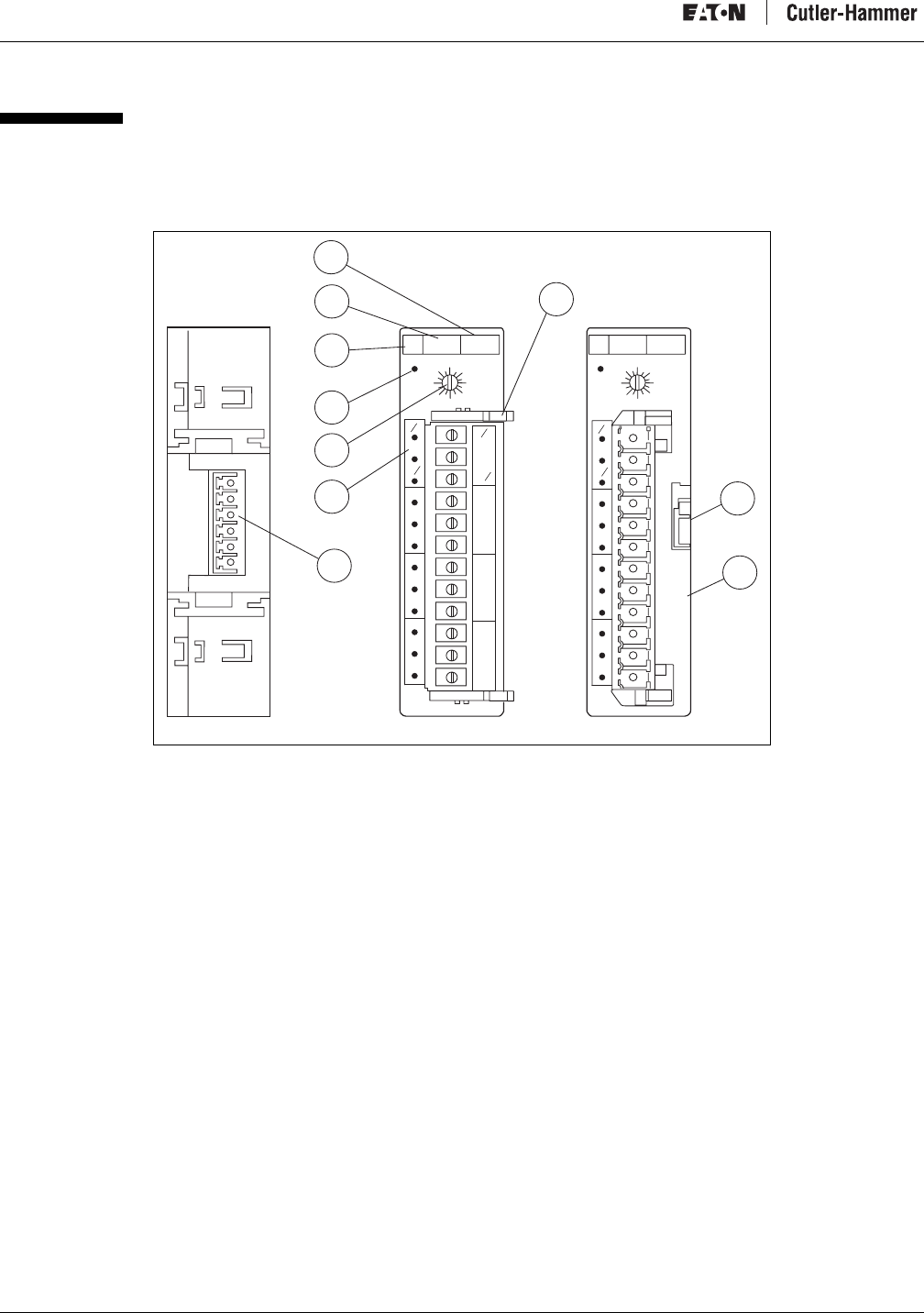
Figure 1 illustrates the front and back of a typical IT. D77A I/O module.
Figure 1: I/O Module Component Location
a) Number of points
b) Terminal Blocks (Removable)
c) DIN Rail Locking Tab
d) D77 Part Number
e) QC Port, Backplane Connector
f) I/O Status LED
g) Group ID Selector Switch (Address)
h) Status LED
i) I/O Type (“I” for Input, “Q” for Output)
j) Voltage (AC, DC, Relay, Analog)
02
4
86
10
12
14 02
4
86
10
12
14
I24V 8 Pt I24V 8 Pt
0
11
C0
0
C0
3
2
C1
2
3
C1
4
5
C2
4
5
C2
6
7
C3
6
7
C3
0
1
C0
2
3
C1
4
5
C2
6
7
C3
IT.IT.
D77A-001
e
f
g
h
i
j
a
c
b
d
D
I
8
Intelligent Technologies (IT.) D77A I/O Module Products
MN05002001E For more information visit: www.EatonElectrical.com 5
Dimensional Data
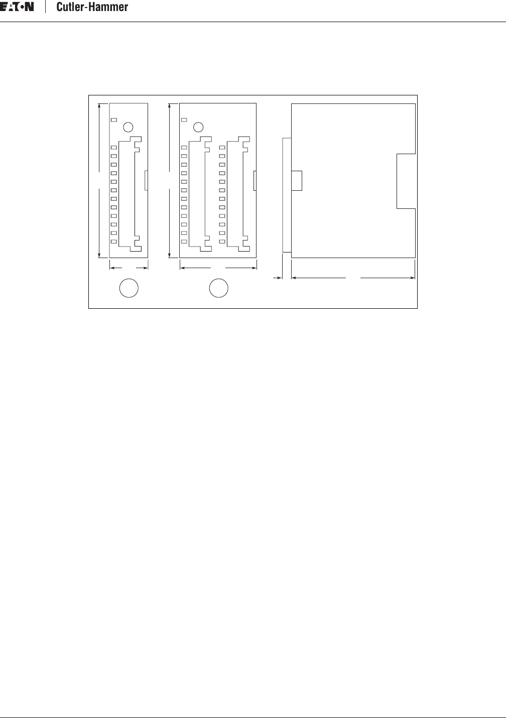
Figure 2 illustrates the dimensional data of the IT. D77A I/O modules.
Figure 2: Module Physical Dimensions, mm [in]
a) Single Wide Module
b) Double Wide Module
Note: Ventilation requirements necessitate a minimum of 50 mm (2 in) on the top and bottom of each module and to each side of a
module grouping.
Power Requirements
The current draw for the IT. D77A I/O modules can be found in the module specification table for each specific module type. When
specifying the 24 volt DC power supply, the power rating must support the sum of all the modules’ current draw added to the system
power requirements.
For more information on the sizing of power supplies, refer to the IT. QCPort System Install and Planning Guide (Publication No.
MN05001002E).
Surge Suppression
IT. D77A Discrete I/O output modules have built-in surge suppression (snubbers) to reduce the effects of transient voltages. When
connecting output devices that have inductive loads (e.g., solenoids, relays, motor starters, etc.) additional surge suppression is
recommended and should be added across the load. The addition of customer-supplied surge suppression for inductive loads
prolongs the D77A output life.
a b
90
[3.5]
45
[1.8] 68
[2.7]
12
[0.5]
90
[3.5]
22.5
[0.9]
D77A-002
Intelligent Technologies (IT.) D77A I/O Module Products
6For more information visit: www.EatonElectrical.com MN05002001E
Environmental Specifications
Table 3: Environmental Ratings
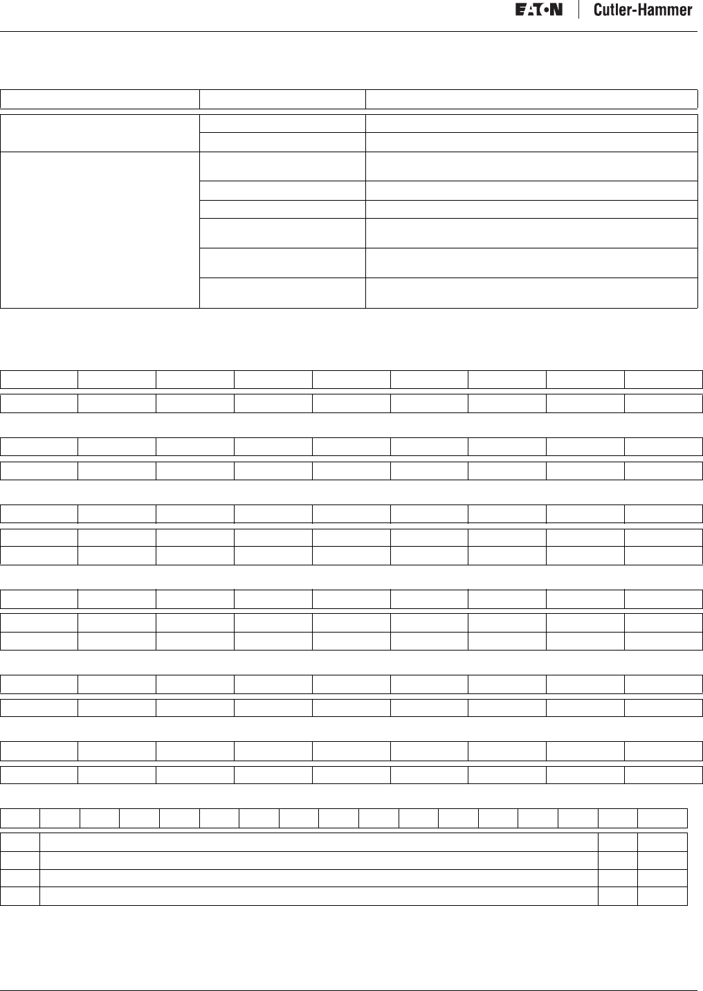
Device Default I/O Data
The following tables display the device default data mapping for D77A I/O modules as the data would appear on a network.
Table 4: 8 Point Discrete Input Module (Produced)
Table 5: 8 Point Discrete Output Module (Consumed)
Table 6: 16 Point Discrete Input Module (Produced)
Table 7: 16 Point Discrete Output Module (Consumed)
Table 8: 16 Point Discrete Combination Module (Produced)
Table 9: 16 Point Discrete Combination Module (Consumed)
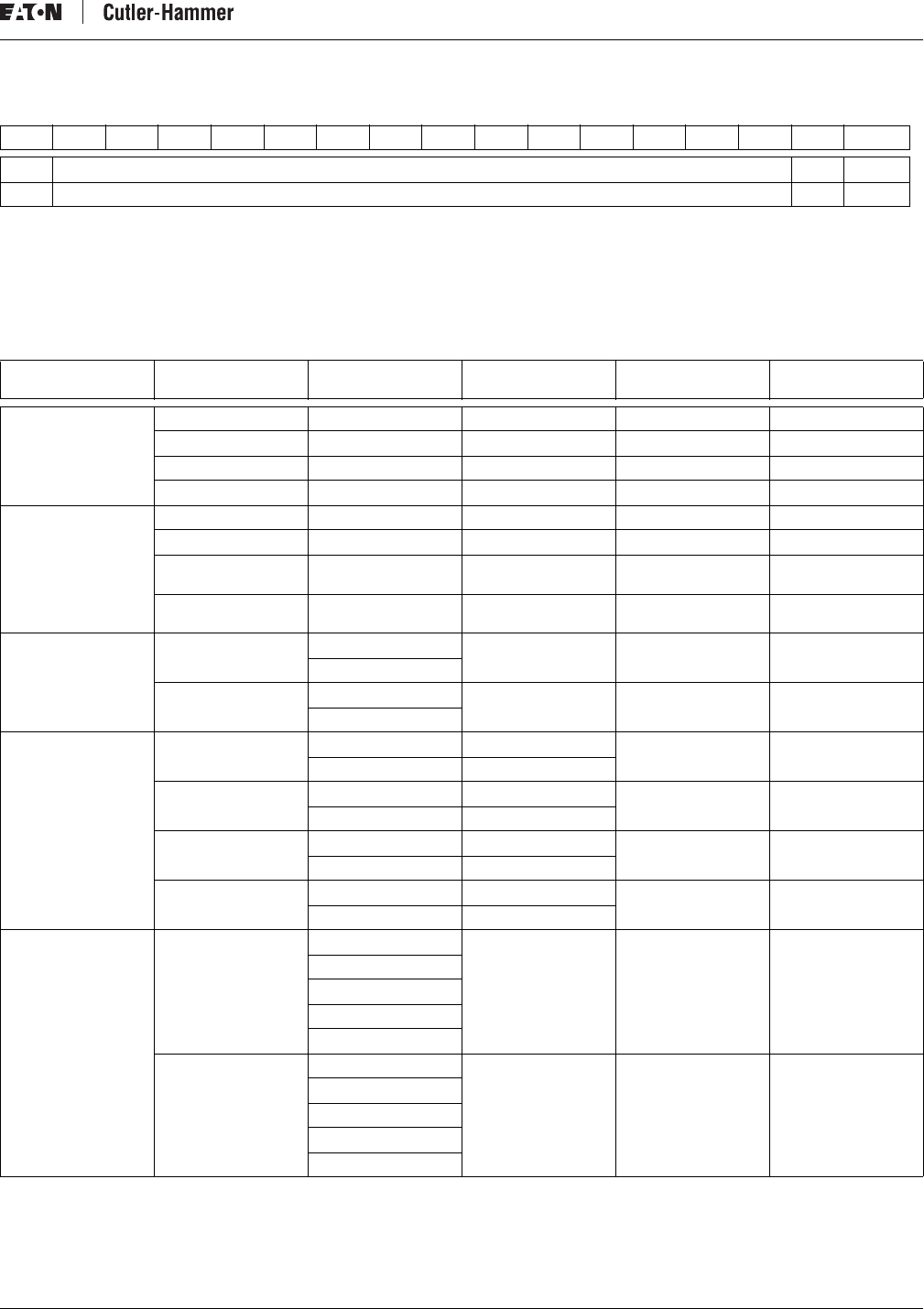
Table 10: 4 Channel Analog Input Module (Produced)
*Sign Bit
1 = True (-)
0 = False (+)
**Not Used
Category Description Specification
Transportation
and Storage Temperature -50°C to 80°C [-58°F to 176°F]
Humidity 5 – 95% non-condensing
Operating Temperature -25°C to 55°C [-13°F to 131°F]
0°C to 55°C [32°F to 131°F] (analog I/O only)
Humidity 5% – 95% non-condensing
Altitude Above 2000 meters [6600 feet] consult factory
Shock
(IEC 68-2-27) 15G any direction for 11 milliseconds
Relay Operation 8G any direction
Vibration
(IEC 68-2-6) 5 – 150 Hz, 5G, 0.7 mm maximum peak-to-peak
Relay Operation 10 – 55 Hz, 3G, 0.7 mm maximum peak-to-peak
Pollution Degree Devices are intended to be installed in a pollution degree 2
environment.
Bit 7Bit 6Bit 5Bit 4Bit 3Bit 2Bit 1Bit 0Byte
I7 I6 I5 I4 I3 I2 I1 I0 0
Bit 7Bit 6Bit 5Bit 4Bit 3Bit 2Bit 1Bit 0Byte
Q7 Q6 Q5 Q4 Q3 Q2 Q1 Q0 0
Bit 7Bit 6Bit 5Bit 4Bit 3Bit 2Bit 1Bit 0Byte
I7 I6 I5 I4 I3 I2 I1 I0 0
I15 I14 I13 I12 I11 I10 I9 I8 1
Bit 7Bit 6Bit 5Bit 4Bit 3Bit 2Bit 1Bit 0Byte
Q7 Q6 Q5 Q4 Q3 Q2 Q1 Q0 0
Q15 Q14 Q13 Q12 Q11 Q10 Q9 Q8 1
Bit 7Bit 6Bit 5Bit 4Bit 3Bit 2Bit 1Bit 0Byte
I7 I6 I5 I4 I3 I2 I1 I0 0
Bit 7Bit 6Bit 5Bit 4Bit 3Bit 2Bit 1Bit 0Byte
Q7 Q6 Q5 Q4 Q3 Q2 Q1 Q0 1
Bit 15 Bit 14 Bit 13 Bit 12 Bit 11 Bit 10 Bit 9 Bit 8 Bit 7 Bit 6 Bit 5 Bit 4 Bit 3 Bit 2 Bit 1 Bit 0 WORD
SB * Analog Input Data/Channel 0 N/A** 0
SB * Analog Input Data/Channel 1 N/A** 1
SB * Analog Input Data/Channel 2 N/A** 2
SB * Analog Input Data/Channel 3 N/A** 3
Intelligent Technologies (IT.) D77A I/O Module Products
MN05002001E For more information visit: www.EatonElectrical.com 7
Table 11: 2 Channel Analog Output Module (Consumed)
*Sign Bit
1 = True (-)
0 = False (+)
**Not Used
I/O Module Summary
Table 12: I/O Devices
Bit 15 Bit 14 Bit 13 Bit 12 Bit 11 Bit 10 Bit 9 Bit 8 Bit 7 Bit 6 Bit 5 Bit 4 Bit 3 Bit 2 Bit 1 Bit 0 WORD
SB * Analog Output Data/Channel 0 N/A** 0
SB * Analog Output Data/Channel 1 N/A** 1
Part Number
Volt age
(Current) Type (I/O) Description Page
AC D77A-AI8 120V AC Input AC Input Module Page 8
D77A-AI16 120V AC Input AC Input Module Page 8
D77A-AQ8 120V AC Output AC Output Module Page 13
D77A-AQ16 120V AC Output AC Output Module Page 13
DC D77A-DI8 24V DC Input DC Input Module Page 9
D77A-DI16 24V DC Input DC Input Module Page 9
D77A-DQ8 24V DC Output DC Sink Output
Module Page 14
D77A-DQ16 24V DC Output DC Sink Output
Module Page 14
Relay D77A-RQ8 0 – 30V DC Output Relay Output Module Page 15
0 – 125V AC
D77A-RQ16 0 – 30V DC Output Relay Output Module Page 15
0 – 125V AC
Combo D77A-DI8DQ8 24V DC Input Combination Module Page 18
24V DC Output
D77A-DI8RQ8 24V DC Input Combination Module Page 19
Relay Output
D77A-AI8AQ8 120V AC Input Combination Module Page 20
120V AC Output
D77A-AI8RQ8 120V AC Input Combination Module Page 21
Relay Output
Analog D77A-NI4 0 – 5V Input Analog Module Page 10
1 – 5V
0 – 10V
0 – 20 mA
4 – 20 mA
D77A-NQ2 0 – 5V Output Analog Module Page 16
1 – 5V
0 – 10V
0 – 20 mA
4 – 20 mA
Intelligent Technologies (IT.) D77A I/O Module Products
8For more information visit: www.EatonElectrical.com MN05002001E
Input Specifications
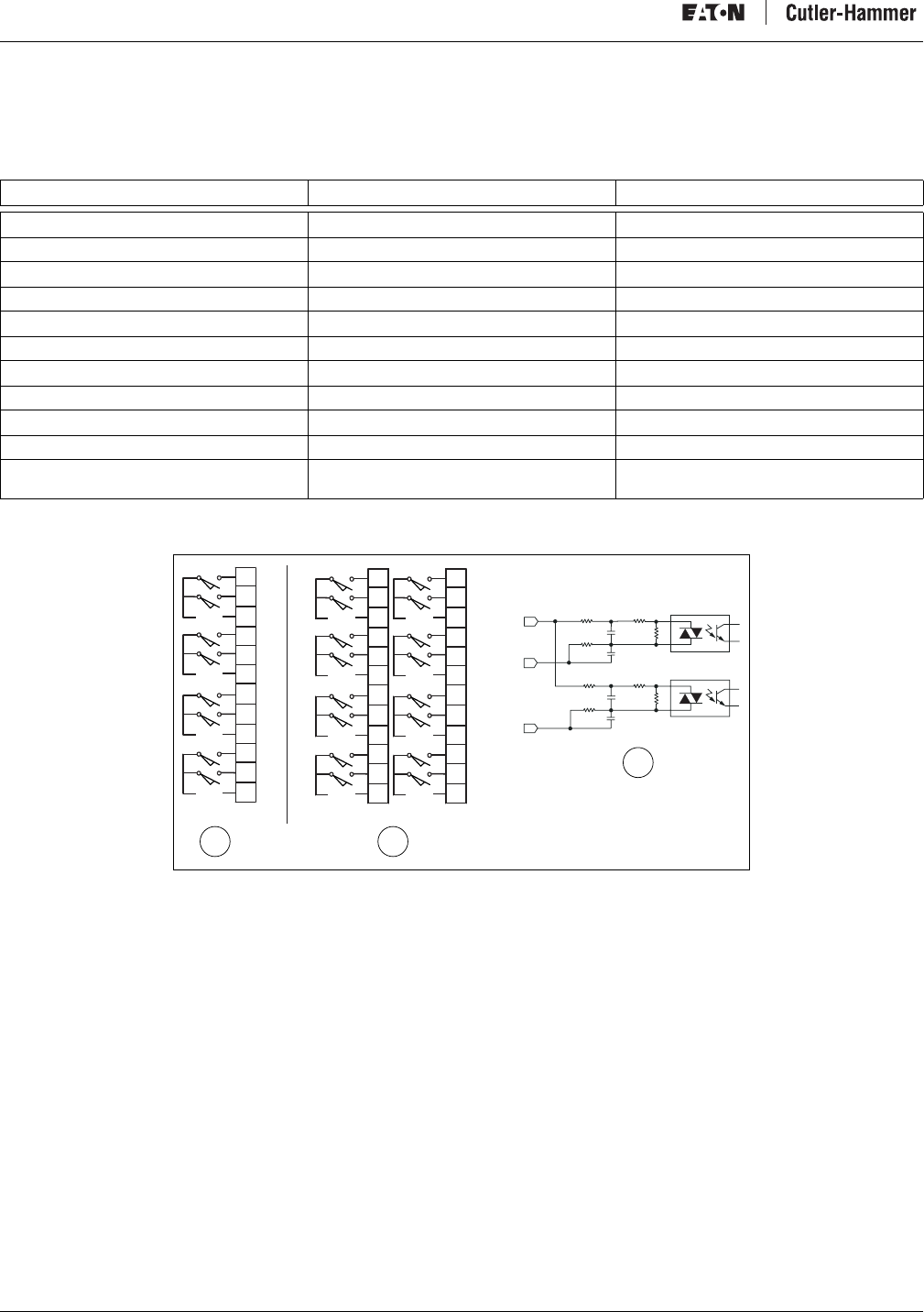
AC Input Module Specifications
Table 13: AC Input Module Specifications
* A 50V transition range exists between 30V and 80V.
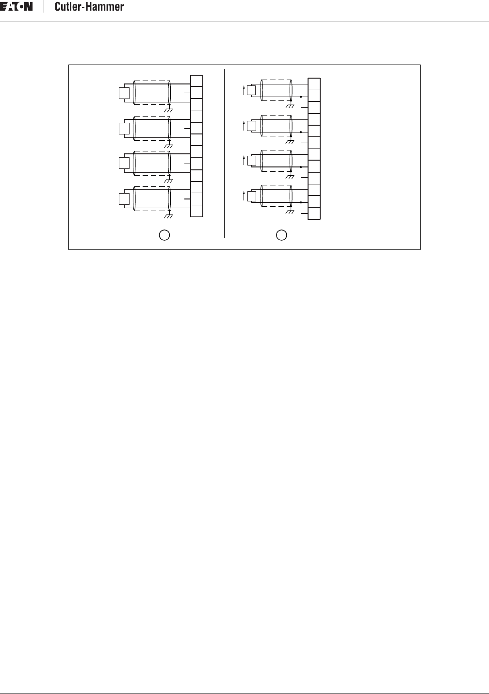
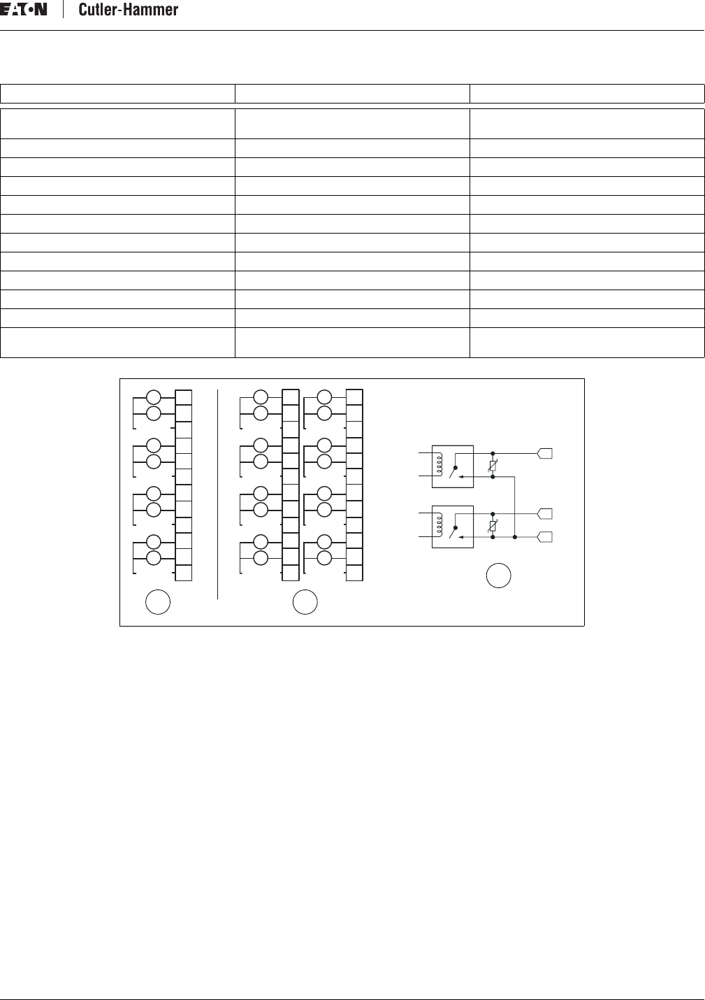
Figure 3: AC Input Module Diagrams
a) D77A-AI8, Eight-Point Module
b) D77A-AI16, Sixteen-Point Module
c) Internal Circuit
Catalog Number D77A-AI8 D77A-AI16
Nominal Input Voltage 120V AC, 50/60 Hz 120V AC, 50/60 Hz
Operating Voltage 80 – 140V AC, 50/60 Hz 80 – 140V AC, 50/60 Hz
Number of Inputs 8 16
Points per Common 2 2
OFF State Voltage 0 – 30V AC * 0 – 30V AC *
ON State Voltage 80V AC – 140V AC 80V AC – 140V AC
Nominal Input Current 15 mA 15 mA
Signal Delay 8.33 ms @ 60 Hz / 10 ms @ 50 Hz 8.33 ms @ 60 Hz / 10 ms @ 50 Hz
QCPort Current Draw 33 mA 46 mA
Isolation 1.5kV 1.5kV
Terminal Screw Torque 4.5 inch-pounds
(0.51 Newton-meters) 4.5 inch-pounds
(0.51 Newton-meters)
COM
IN
IN
Ø
1
CØ
2
3
C1
4
5
C2
6
7
C3
VAC
VAC
VAC
VAC
Ø
1
CØ
2
3
C1
4
5
C2
6
7
C3
VAC VAC
VAC VAC
VAC VAC
VAC VAC
8
9
C4
10
11
C5
12
13
C6
14
15
C7
ab
c
D77A-006
Intelligent Technologies (IT.) D77A I/O Module Products
MN05002001E For more information visit: www.EatonElectrical.com 9
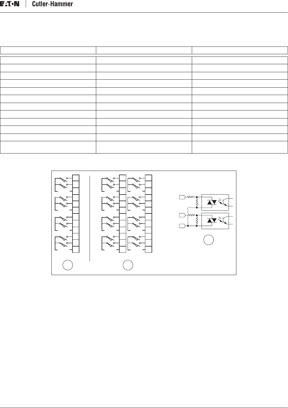
DC Input Module Specifications
Table 14: DC Input Module Specifications
* A 12V transition range exists between 6V and 18V.
Figure 4: DC Input Module Diagrams
a) D77A-DI8, Eight-point Module
b) D77A-DI16, Sixteen-point Module
c) Internal Circuit
Catalog Number D77A-DI8 D77A-DI16
Type Sink/Source Sink/Source
Nominal Input Voltage 24V DC 24V DC
Operating Voltage 18 – 30V DC 18 – 30V DC
Number of Inputs 8 16
Points per Common 2 2
Signal Delay 5 ms 5 ms
OFF State Voltage 0 – 6V DC * 0 – 6V DC *
ON State Voltage 18V – 30V DC 18V – 30V DC
Nominal Input Current 5 mA 5 mA
QCPort Current Draw 35 mA 63 mA
Isolation 1.5kV 1.5kV
Terminal Screw Torque 4.5 inch-pounds
(0.51 Newton-meters) 4.5 inch-pounds
(0.51 Newton-meters)
IN
IN
COM
Ø
1
CØ
2
3
C1
4
5
C2
6
7
C3
VDC
VDC
VDC
VDC
Ø
1
CØ
2
3
C1
4
5
C2
6
7
C3
VDC
VDC
VDC
VDC
VDC
VDC
VDC
VDC
8
9
C4
10
11
C5
12
13
C6
14
15
C7
D77A-008
ab
c
Intelligent Technologies (IT.) D77A I/O Module Products
10 For more information visit: www.EatonElectrical.com MN05002001E
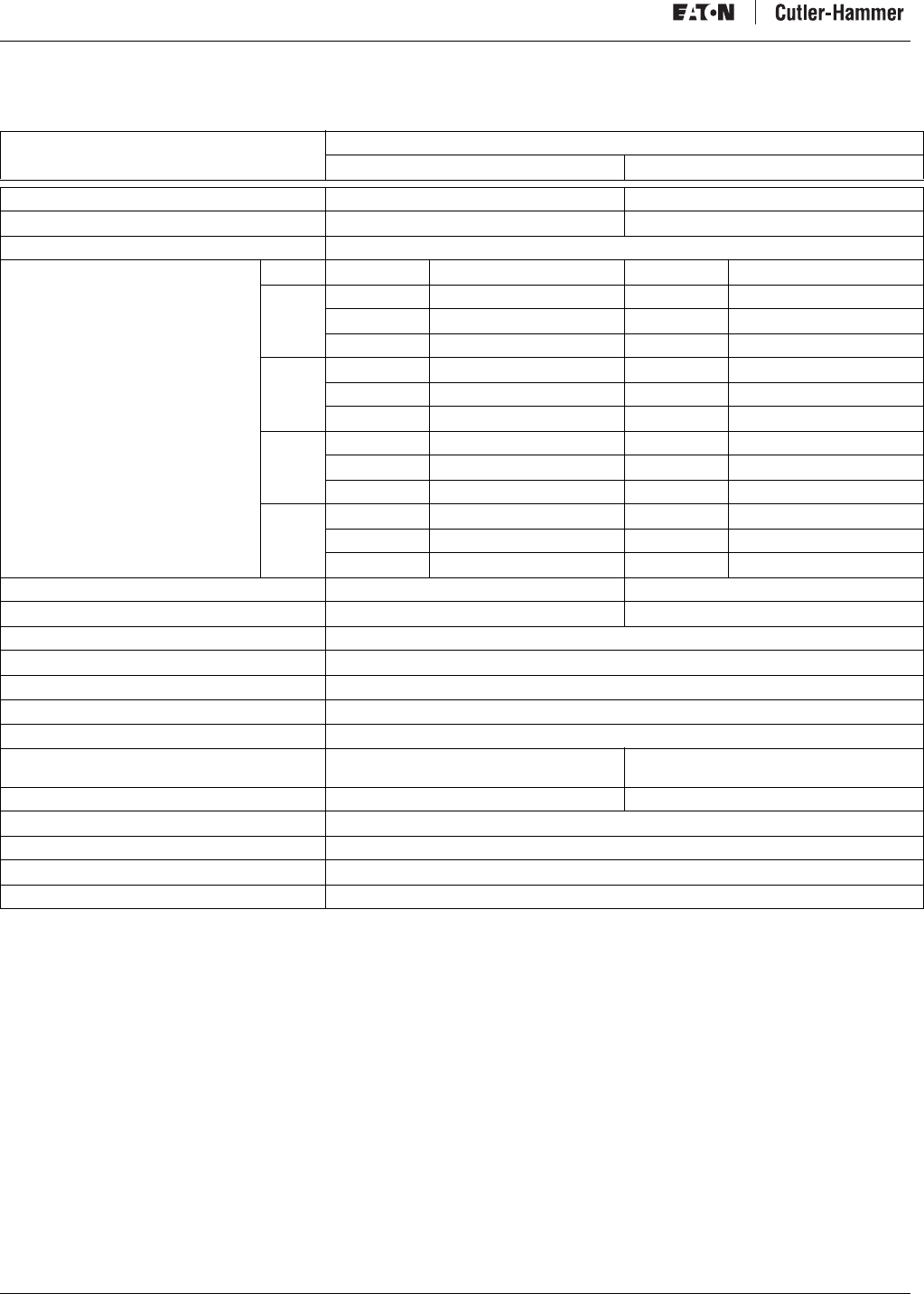
Analog Input Module Specifications
Table 15: D77A-NI4 Analog Input Module Specifications
(See Figure 5 for circuit diagram)
Catalog Number
D77A-NI4
Voltage Input Current Loop Input
Voltage Input 0 – 5V, 1 – 5V, 0 – 10V DC —
Current Input — 4 – 20 mA, 0 – 20 mA
Input Type Single End, Uni-polar
Resolution
Note: Input filter settings affect the
effective resolution of the channels.
Voltage Resolution Current Resolution
50Hz 0-5VDC 14 bit 0-20mA 14 bit
0-10VDC 14 bit 4-20mA 14 bit
1-5VDC 14 bit
60Hz 0-5VDC 14 bit 0-20mA 14 bit
0-10VDC 14 bit 4-20mA 14 bit
1-5VDC 14 bit
250Hz 0-5VDC 14 bit 0-20mA 12 bit
0-10VDC 13 bit 4-20mA 12 bit
1-5VDC 12 bit
500Hz 0-5VDC 9 bit 0-20mA 9 bit
0-10VDC 10 bit 4-20mA 9 bit
1-5VDC 9 bit
Input Full Scale Range 0 – 10.5V or 0 – 5.25V 0 – 21 mA
Maximum Overload at Input Terminal 30VDC 32 mA
Number of Channels 4
Selectable Input Filter Frequency 50Hz, 60Hz, 250Hz, 500Hz
Input Group-to-Bus Isolation 500 VAC for 60 seconds
Common Mode Rejection Greater than 60 db @ 50/60 Hz
Normal Mode Rejection ratio -50 db @ 50/60 Hz
Accuracy +/– 0.3% Full Scale @ 25°C
+/– 0.4% Full Scale @ 0-55°C +/– 0.45% Full Scale @ 25°C
+/– 0.5% Full Scale @ 0-55°C
Input Impedance 15M ohm 250 ohm
Operating Temperature 0–55°C
Status LED Indication Module Status
QCPort Current Draw 60 mA
Terminal Screw Torque 4.5 inch-pounds (0.51 Newton-meters)
Intelligent Technologies (IT.) D77A I/O Module Products
MN05002001E For more information visit: www.EatonElectrical.com 11
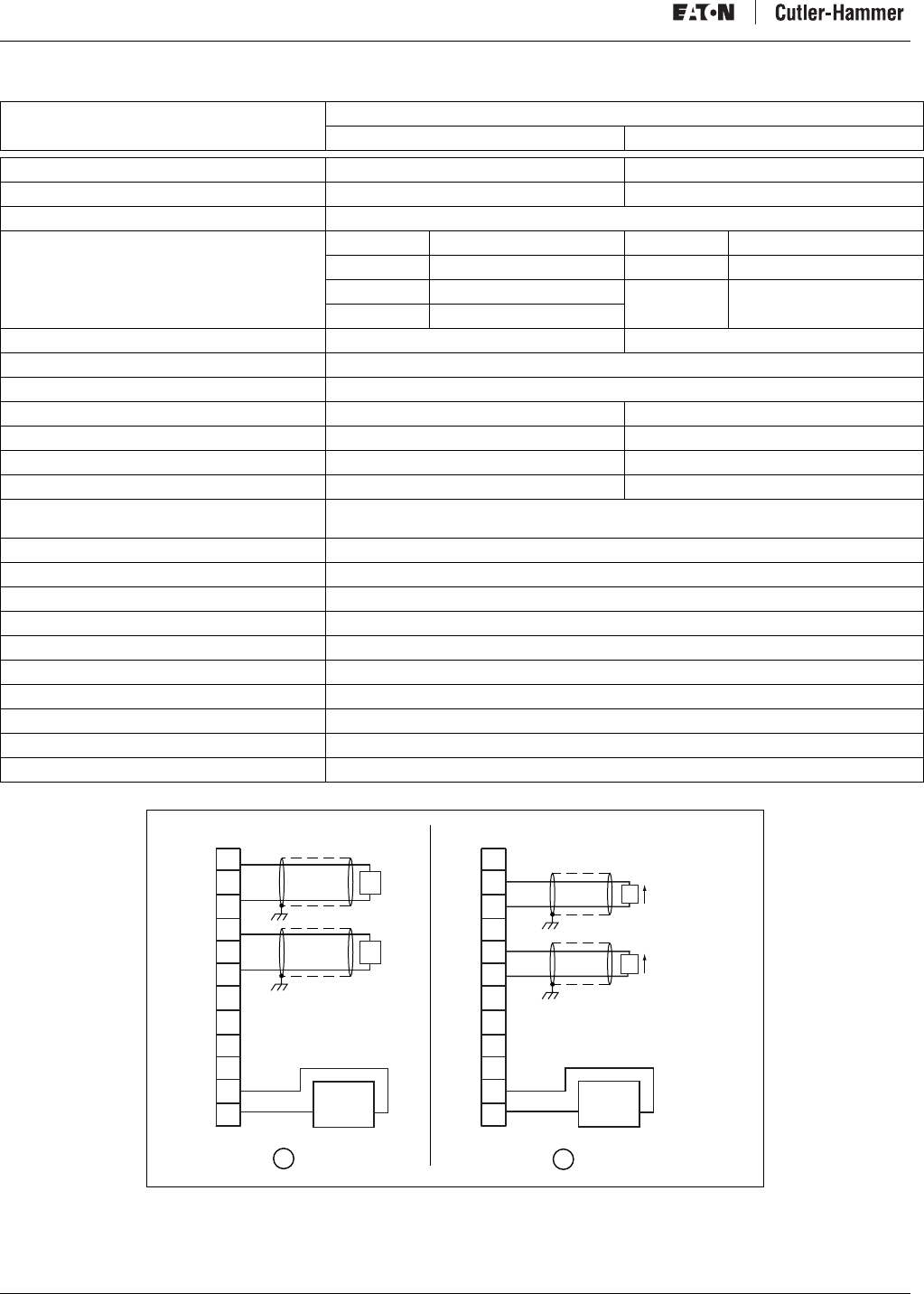
Figure 5: D77A-NI4 Analog Input Module Diagrams
a) D77A-NI4 Voltage Input Channels
b) D77A-NI4 Current Input Channels
(See D77A-NI4 Analog Input Module Specifications on page 10)
V0
I0
C0
V1
I1
C1
V2
I2
C2
V3
I3
C3
V0
I0
C0
V1
I1
C1
V2
I2
C2
V3
I3
C3
JIC-0013
a b
NC
NC
NC
NC
(I)
(I)
(I)
(I)
(V)
(V)
(V)
(V)
+
-
+
-
+
-
+
-
Intelligent Technologies (IT.) D77A I/O Module Products
12 For more information visit: www.EatonElectrical.com MN05002001E
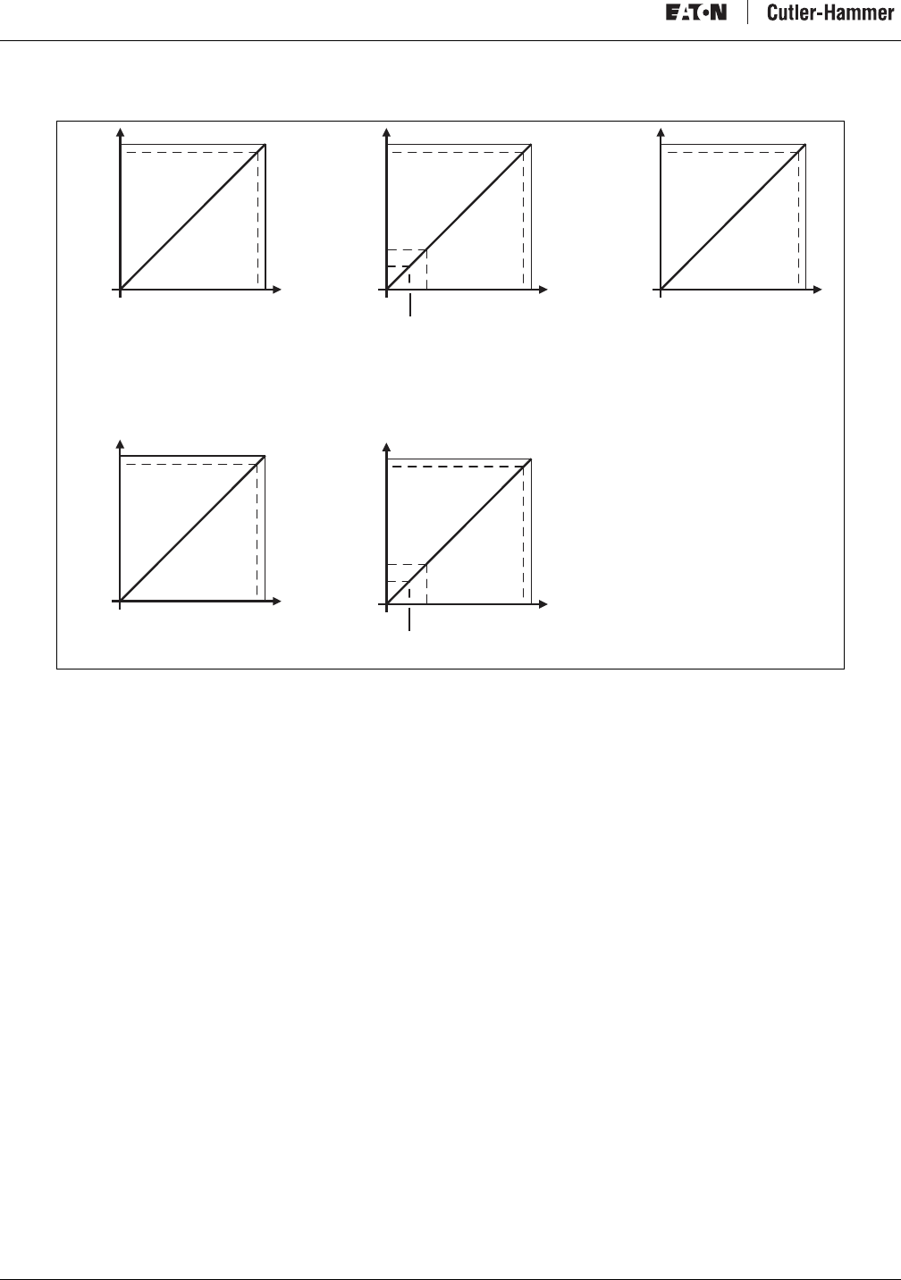
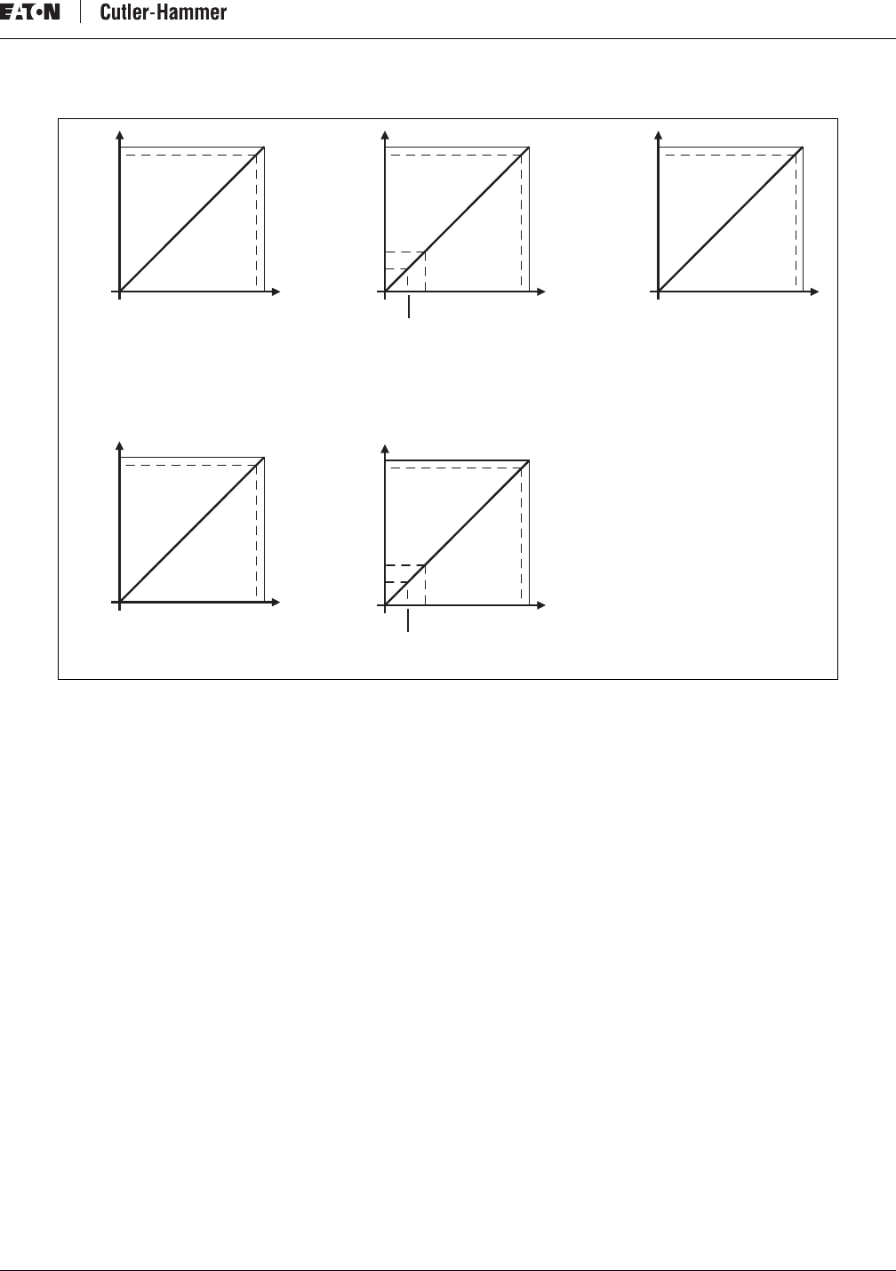
Figure 6: Analog Input Curves
a) 0-5V Range Setting
b) 1-5V Range Setting
c) 0-10V Range Setting
d) 0-20mA Range Setting
e) 4-20mA Range Setting
14 Bit Resolution Equations
Vdc = Voltage input value
mA = Current input value
N = Decimal value
0-5 Vdc, 1-5 Vdc
•Vdc = (1/6241.2) x N
0-10 Vdc
•Vdc = (1/3120.6) x N
4-20 mA, 0-20 mA
•mA = (1/1560.2) x N
5.25V5V
0V
0
32766
31206
21mA20mA0mA
0
5.25V5V
0V
0
32766
31206
32766
31206
10.5V10V
0V
0
1V
0.5V
6242
3120
21mA20mA0mA
0
32766
31206
32766
31206
4mA
6242
4992
(A)
(D) (E)
(B) (C)
D77A-031
3.2mA
Intelligent Technologies (IT.) D77A I/O Module Products
MN05002001E For more information visit: www.EatonElectrical.com 13
Output Specifications
AC Output Module Specifications
Table 16: AC Output Module Specifications
Figure 7: AC Output Module Diagrams
a) D77A-AQ8, Eight-Point Module
b) D77A-AQ16, Sixteen-Point Module
c) Internal Circuit
Catalog Number D77A-AQ8 D77A-AQ16
Nominal Output Voltage 120V AC, 50/60 Hz 120V AC, 50/60 Hz
Operating Voltage 80 – 140V AC, 50/60 Hz 80 – 140V AC, 50/60 Hz
Number of Outputs 8 16
Points per Common 2 2
Minimum Load Current (Resistive) 15 mA 15 mA
Max. Current/Point (Resistive) .5A @ 30°C
.1A @ 55°C .5A @ 30°C
.1A @ 55°C
Max. Current/Module (Resistive) .4A @ 30°C
.8A @ 0-55°C 8A @ 30°C
1.6A @ 0-55°C
Surge Current (10 ms) 10A 10A
OFF State Leakage 2 mA 2 mA
Signal Delay 8.33 ms @ 60 Hz
10 ms @ 50 Hz 8.33 ms @ 60 Hz
10 ms @ 50 Hz
QCPort Current Draw 120 mA 220 mA
Isolation 1.5kV 1.5kV
Terminal Screw Torque 4.5 inch-pounds
(0.51 Newton-meters) 4.5 inch-pounds
(0.51 Newton-meters)
L2
OUT
OUT
CR
CR
VAC
VAC
VAC
VAC
Ø
1
CØ
2
3
C1
4
5
C2
6
7
C3
CR
CR
CR
CR
CR
CR
8
9
C4
10
11
C5
12
13
C6
14
15
C7
CR
CR
VAC
VAC
VAC
VAC
VAC
VAC
VAC
VAC
1
2
CØ
2
3
C1
4
5
C2
6
7
C3
CR
CR
CR
CR
CR
CR
CR
CR
CR
CR
CR
CR
CR
CR
D77A-007
ab
c
Intelligent Technologies (IT.) D77A I/O Module Products
14 For more information visit: www.EatonElectrical.com MN05002001E
DC Output Module Specifications
Table 17: DC Output Module Specifications
Figure 8: DC Output Module Diagrams
a) D77A-DQ8, Eight-Point Module
b) D77A-DQ16, Sixteen-Point Module
c) Internal Circuit
Catalog Number D77A-DQ8 D77A-DQ16
Type MOSFET Sink MOSFET Sink
Nominal Output Voltage 24V DC 24V DC
Operating Voltage 18 – 30V DC 18 – 30V DC
Number of Inputs 8 16
Points per Common 4 4
Signal Delay 1 ms 1 ms
Max. Current/Point 0.75A 0.75A
Max. Current/Module (Resistive) 6A 12A
Surge Current (10 ms) 4A 4A
OFF State Leakage 1 mA 1 mA
QCPort Current Draw 85 mA 126 mA
Isolation 1.5kV 1.5kV
Terminal Screw Torque 4.5 inch-pounds
(0.51 Newton-meters) 4.5 inch-pounds
(0.51 Newton-meters)
+24
OU
T
OU
T
C
CR
COM
COM
Ø
1
2
3
-
+
4
5
6
7
-
+
VDC
VDC
CR
CR
CR
CR
CR
CR
CR
8
9
10
11
-
+
12
13
14
15
-
+
CR
COM COM
COM COM
Ø
1
2
3
-
+
4
5
6
7
-
+
VDC VDC
VDC VDC
CR
CR
CR
CR
CR
CR
CR
CR
CR
CR
CR
CR
CR
CR
CR
D77A-009
ab
c
Intelligent Technologies (IT.) D77A I/O Module Products
MN05002001E For more information visit: www.EatonElectrical.com 15
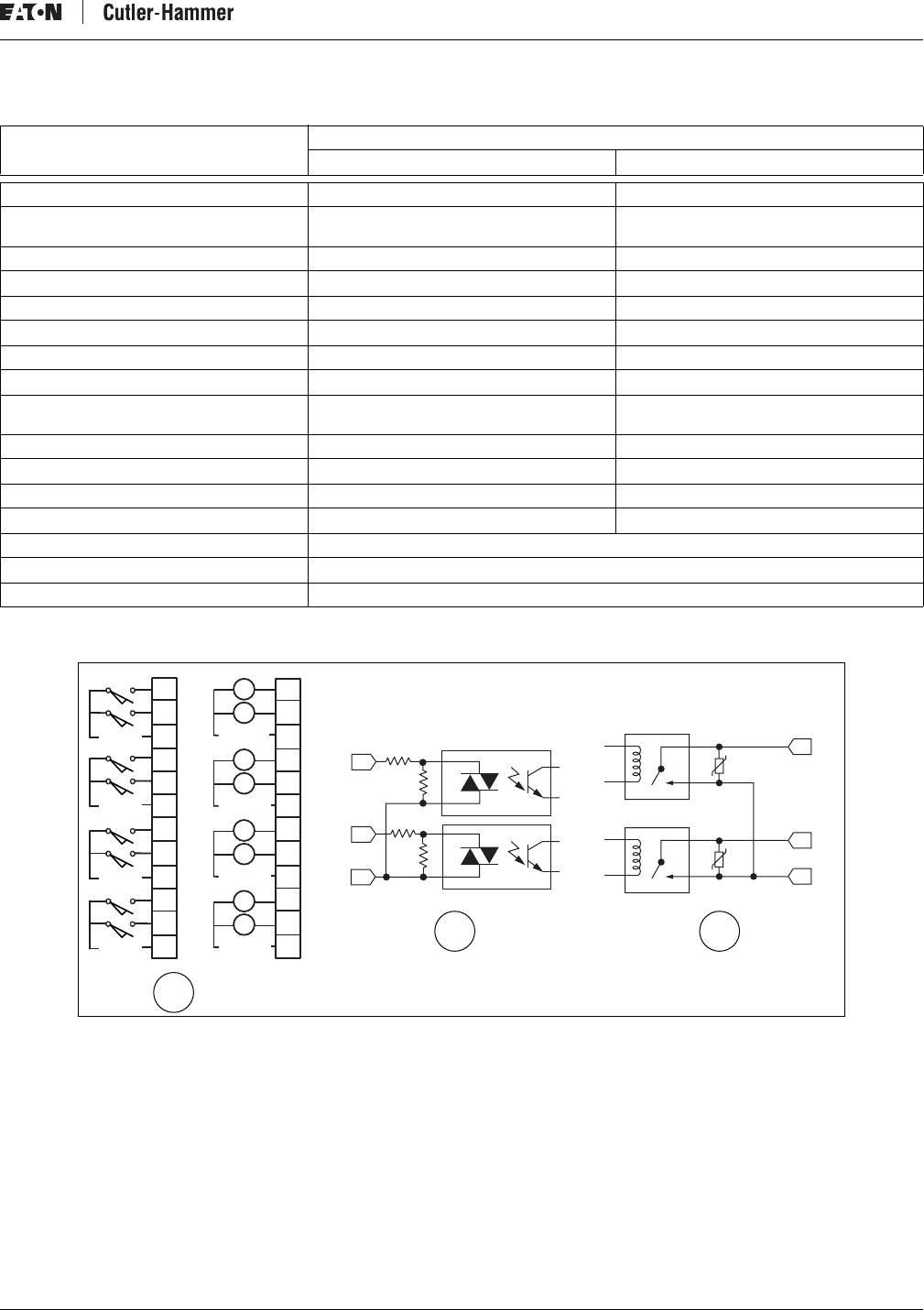
Relay Output Module Specifications
Table 18: Relay Output Module Specifications
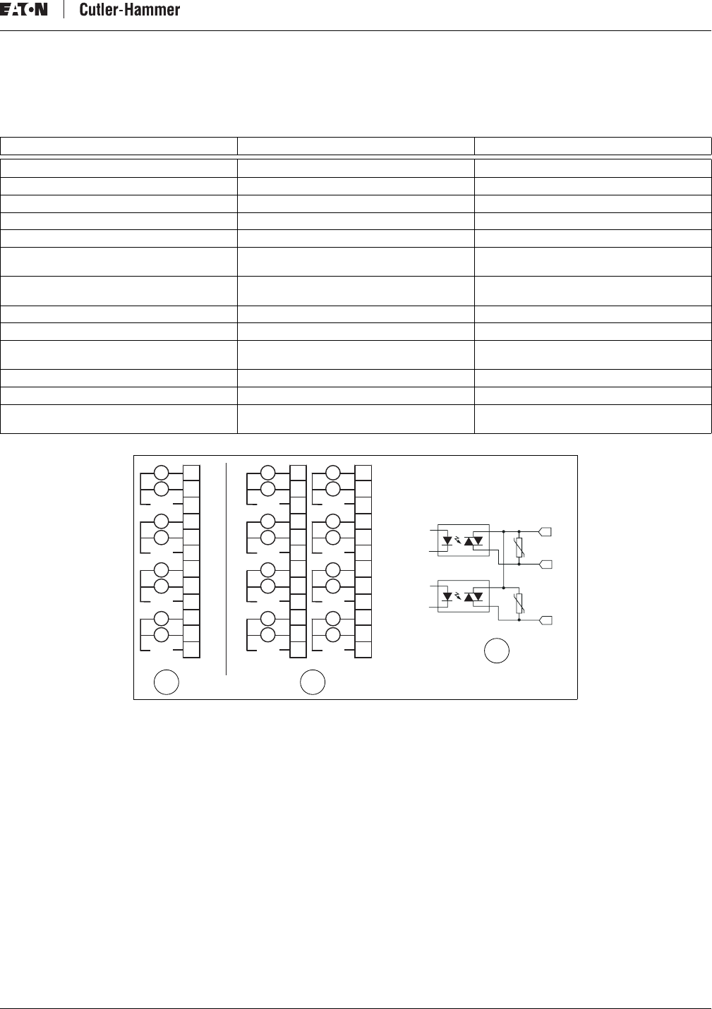
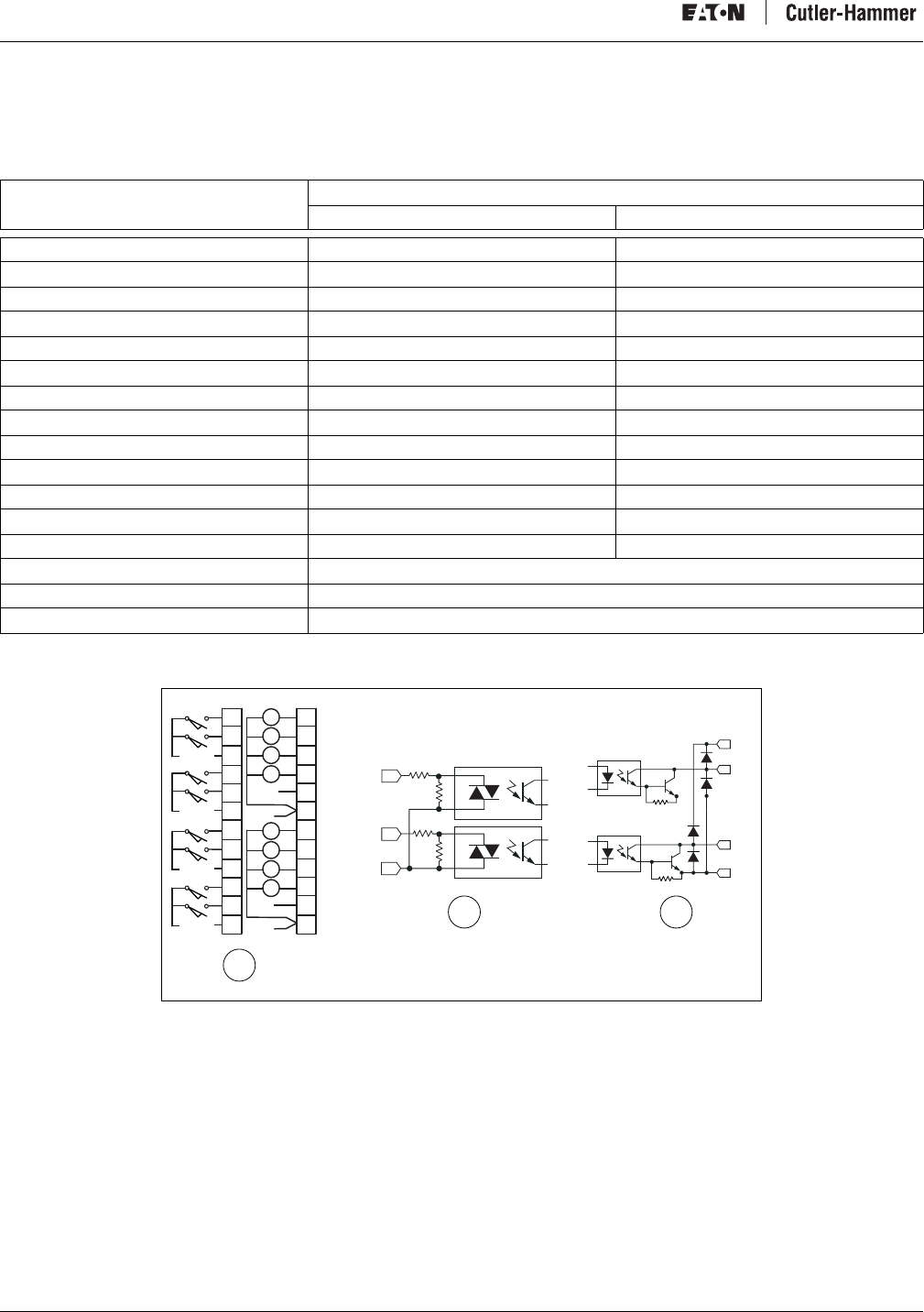
Figure 9: Relay Output Module Diagrams
a) D77A-RQ8, Eight-point Module
b) D77A-RQ16, Sixteen-point Module
c) Internal Circuit
Catalog Number D77A-RQ8 D77A-RQ16
Nominal Output Voltage 0 – 140V AC
0 – 30V DC 0 – 140V AC
0 – 30V DC
Number of Outputs 8 16
Points per Common 2 2
Relay OFF Time 6 ms 6 ms
Relay ON Time 3 ms 3 ms
Max. Current/Point (Resistive) 3 A 3 A
Max. Current/Module (Resistive) 24 A 48 A
Electrical Life 100,000 Cycles 100,000 Cycles
Mechanical Life 1,000,000 Cycles 1,000,000 Cycles
QCPort Current Draw 92 mA 164 mA
Isolation 1.5 kV 1.5 kV
Terminal Screw Torque 4.5 inch-pounds
(0.51 Newton-meters) 4.5 inch-pounds
(0.51 Newton-meters)
OUT
OUT
C
CR
CR
VAC/DC
VAC/DC
VAC/DC
VAC/DC
Ø
1
CØ
2
3
C1
4
5
C2
6
7
C3
CR
CR
CR
CR
CR
CR
8
9
C4
10
11
C5
12
13
C6
14
15
C7
CR
CR
Ø
1
CØ
2
3
C1
4
5
C2
6
7
C3
VAC/DC
VAC/DC
VAC/DC
VAC/DC
VAC/DC
VAC/DC
VAC/DC
VAC/DC
CR
CR
CR
CR
CR
CR
CR
CR
CR
CR
CR
CR
CR
CR
D77A-010
ab
c
Intelligent Technologies (IT.) D77A I/O Module Products
16 For more information visit: www.EatonElectrical.com MN05002001E
Analog Output Module Specifications
Table 19: D77A-NQ2 Analog Output Module Specifications
Figure 10: D77A-NQ2 Combination Module Diagrams
a) D77A-NQ2 Module, Voltage Output Channels
b) D77A-NQ2 Module Current Output Channels
See D77A-NQ2 Analog Output Module Specifications on page 16
Catalog Number
D77A-NI4
Voltage Output Current Loop Output
Voltage Output 0 – 5V, 1 – 5V, 0 – 10V DC —
Current Output — 4 – 20 mA, 0 – 20 mA
Output Type Single End, Uni-polar
Resolution Voltage Resolution Current Resolution
0-5VDC 13bit 0-20mA 14 bit
0-10VDC 14 bit 4-20mA 14 bit
1-5VDC 13 bit
Output Full Scale Range 0 – 10.5V or 0 – 5.25V 0 – 21 mA
Maximum Overload at Input Terminal 36V DC
Number of Channels 2
Resistive Load — Less than 500 ohms
Load Range Greater than 1k ohm —
Maximum Inductive Load — 0.1 mH
Maximum Capacitive Load 1 µF —
Accuracy +/– 0.8% Full Scale @ 25°C
+/– 1.0% Full Scale @ 0-55°C
Update Rate 350 NS
Output Impedance 10 ohm
Output Ripple (0-50 Hz) +/-0.1%
Operating Temperature 0–55°C
Status LED Indication Module Status
QCPort Current Draw 40 mA
External Power 24 VDC, 60 mA Maximum
Output group-to-bus Isolation 1.5kV for 60 Sec.
Terminal 12 Pins (Pitch, 5.2 mm)
Terminal Screw Torque 4.5 inch-pounds (0.51 Newton-meters)
JIC-0014
24VDC
+-
NC
NC
NC
NC
24VDC
+
+-
-
(V)
(V)
+
-
+
-
(I)
(I)
V0
I0
C0
V1
I1
C1
NC
NC
NC
NC
+
-
V0
I0
C0
V1
I1
C1
ab
Intelligent Technologies (IT.) D77A I/O Module Products
MN05002001E For more information visit: www.EatonElectrical.com 17
Figure 11: Analog Output Curves for 14 Bit Resolution
a) 0-5V Range Setting
b) 1-5V Range Setting
c) 0-10V Range Setting
d) 0-20mA Range Setting
e) 4-20mA Range Setting
14 Bit Resolution Equations
Vdc = Voltage input value
mA = Current input value
N = Decimal value
0-5 Vdc, 1-5 Vdc
•Vdc = (1/6241.2) x N
0-10 Vdc
•Vdc = (1/3120.6) x N
4-20 mA, 0-20 mA
•mA = (1/1560.2) x N
5.25V5V
0V
0
32766
31206
21mA20mA0mA
0
5.25V5V
0V
0
32766
31206
32766
31206
10.5V10V
0V
0
1V
0.5V
6242
3120
21mA20mA0mA
0
32766
31206
32766
31206
4mA
6242
4992
(A)
(D) (E)
(B) (C)
D77A-031
3.2mA
Intelligent Technologies (IT.) D77A I/O Module Products
18 For more information visit: www.EatonElectrical.com MN05002001E
Special I/O Specifications
Combination Module Specifications
Table 20: D77A-DI8DQ8 Combination Module Specifications
* A 12V transition range exists between 6V and 18V.
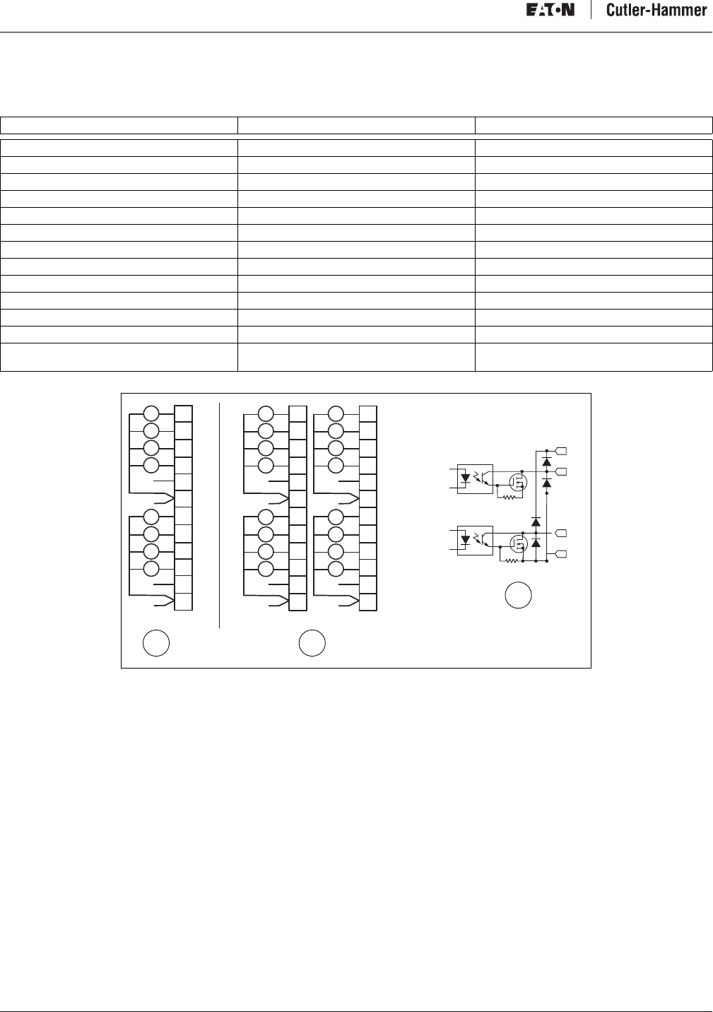
Figure 12: D77A-DI8DQ8 Combination Module Diagrams
a) D77A-DI8DQ8 Module
b) Internal DC Input Circuit
c) Internal DC Output Circuit
Catalog Number
D77A-DI8DQ8
DC Sink/Source Input DC MOSFET Sink Output
Nominal Voltage 24V DC 24V DC
Operating Voltage 18 – 30V DC 18 – 30V DC
Number of Points 8 8
Points per Common 2 2
Signal Delay 5 ms —
OFF State Voltage 0 – 6V DC * —
ON State Voltage 18V – 30V DC —
Nominal Current 5 mA —
Signal Delay — 1 ms
Max. Current/Point (Resistive) — 0.75A
Max. Current/Module (Resistive) — 6A
Surge Current (10 ms) — 4A
OFF State Leakage — 1 mA
QCPort Current Draw 99 mA
Isolation 1.5kV
Terminal Screw Torque 4.5 inch-pounds (0.51 Newton-meters)
IN
IN
COM
Ø
1
CØ
2
3
C1
4
5
C2
6
7
C3
VDC
VDC
VDC VDC
VDC
VDC
CR
COM
COM
Ø
1
2
3
-
+
4
5
6
7
-
+
CR
CR
CR
CR
CR
CR
CR
D77A-011
+24
OU
T
OU
T
C
a
bc
Intelligent Technologies (IT.) D77A I/O Module Products
MN05002001E For more information visit: www.EatonElectrical.com 19
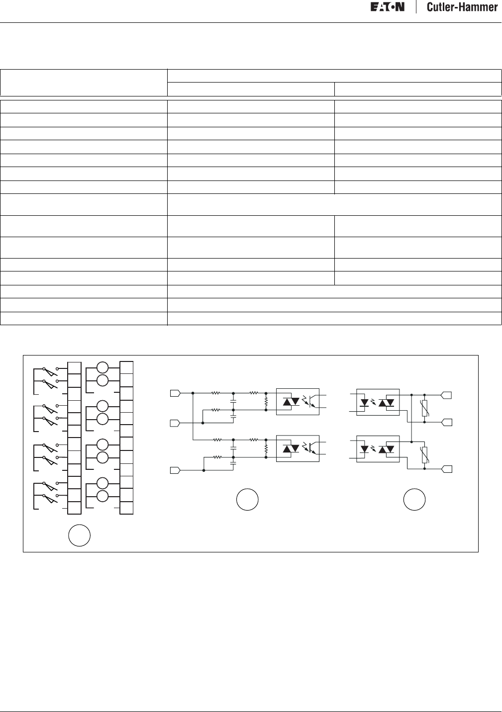
Table 21: D77A-DI8RQ8 Combination Module Specifications
* A 12V transition range exists between 6V and 18V.
Figure 13: D77A-DI8RQ8 Combination Module Diagrams
a) D77A-DI8RQ8 Module
b) Internal DC Input Circuit
c) Internal Relay Output Circuit
Catalog Number
D77A-DI8RQ8
DC Sink/Source Input Relay Output
Nominal Voltage 24V DC —
Operating Voltage 18-30V DC 0-140V AC
0-30V DC
Number of Points 8 8
Points per Common 2 2
Signal Delay 5 ms —
OFF State Voltage 0-6V DC * —
ON State Voltage 18V-30V DC —
Nominal Current 5 mA —
Signal Delay — Relay ON Time 3 ms
Relay OFF Time 6 ms
Max. Current/Point (Resistive) — 3A
Max. Current/Module (Resistive) — 24A
Mechanical Life — 1,000,000 Operations
Electrical Life — 100,000 Operations
QCPort Current Draw 121 mA
Isolation 1.5kV
Terminal Screw Torque 4.5 inch-pounds (0.51 Newton-meters)
IN
IN
COM
Ø
1
CØ
2
3
C1
4
5
C2
6
7
C3
VDC
VDC
VDC
VDC
D77A-028
a
bc
OUT
OUT
C
CR
CR
VAC/DC
VAC/DC
VAC/DC
VAC/DC
Ø
1
C4
2
3
C5
4
5
C6
6
7
C7
CR
CR
CR
CR
CR
CR
Intelligent Technologies (IT.) D77A I/O Module Products
20 For more information visit: www.EatonElectrical.com MN05002001E
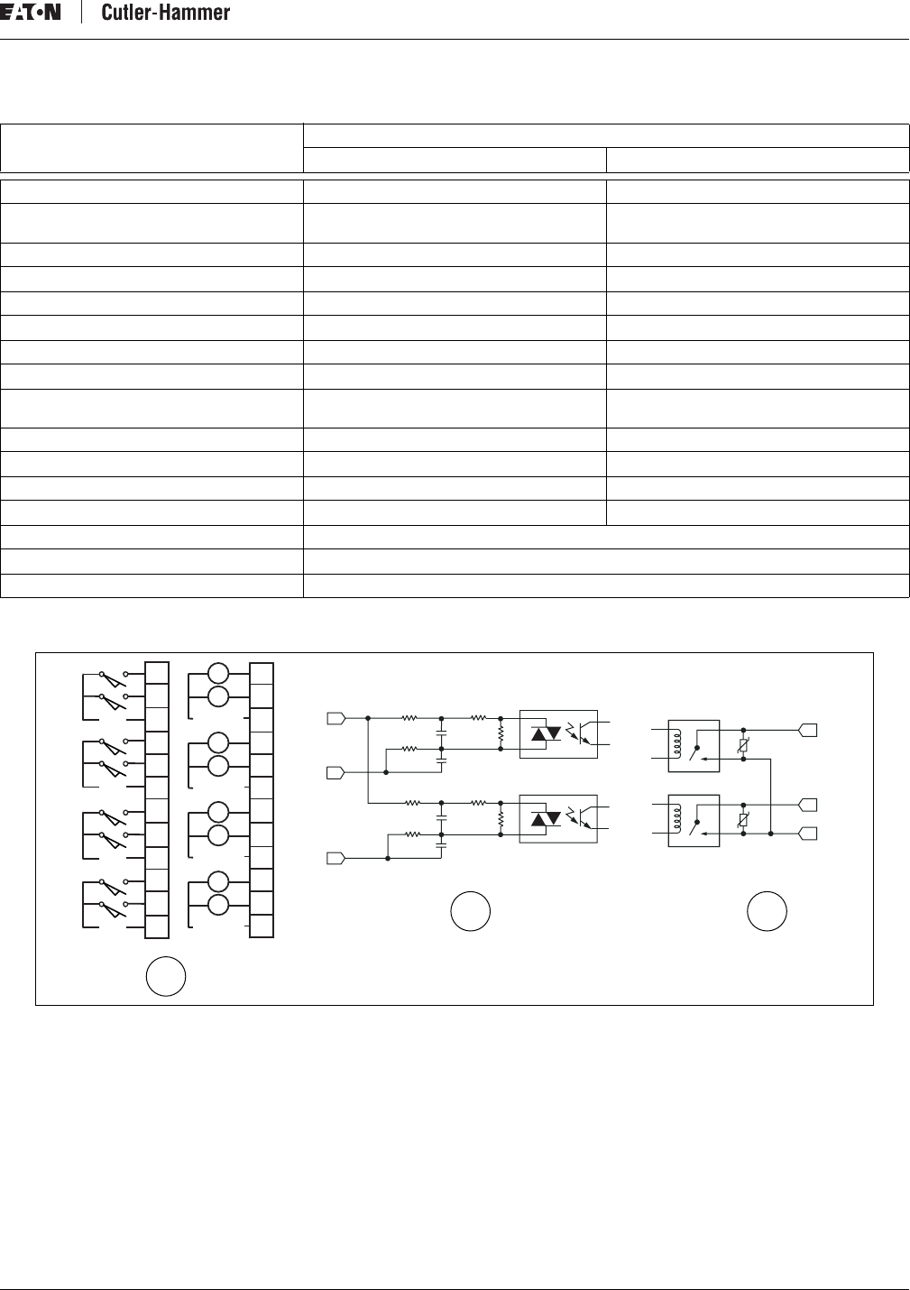
Table 22: D77A-AI8AQ8 Combination Module Specifications
* A 50V transition range exists between 30V and 80V.
Figure 14: D77A-AI8AQ8 Combination Module Diagrams
a) D77A-AI8AQ8 Module
b) Internal AC Input Circuit
c) Internal AC Output Circuit
Catalog Number
D77A-AI8AQ8
AC Input AC Output
Nominal Voltage 120V AC, 50/60 Hz 120V AC, 50/60 Hz
Operating Voltage 80-140V AC 80-140 V AC
Number of Points 8 8
Points per Common 2 2
OFF State Voltage 0-30V AC * —
ON State Voltage 80V-140V AC —
Minimal Load Current (Resistive) 15 mA —
Signal Delay 8.33 ms @ 60 Hz
10 ms @ 50 Hz
Max. Current/Point (Resistive) — 0.5A @ 30°C
0.1A @ 55°C
Max. Current/Module (Resistive) — 4A @ 30°C
0.8A @ 55°C
Surge Current (10 ms) — 10A
OFF State Leakage 2 mA
QCPort Current Draw 132 mA
Isolation 1.5kV
Terminal Screw Torque 4.5 inch-pounds (0.51 Newton-meters)
Ø
1
CØ
2
3
C1
4
5
C2
6
7
C3
VAC
VAC
VAC
VAC
D77A-029
a
bc
COM
IN
IN
L2
OUT
OUT
CR
CR
Ø
1
C4
2
3
C5
4
5
C6
6
7
C7
VAC
VAC
VAC
VAC
CR
CR
CR
CR
CR
CR
Intelligent Technologies (IT.) D77A I/O Module Products
MN05002001E For more information visit: www.EatonElectrical.com 21
Table 23: D77A-AI8RQ8 Combination Module Specifications
* A 60V transition range exists between 80V and 140V.
Figure 15: D77A-AI8RQ8 Combination Module Diagrams
a) D77A-AI8RQ8 Module
b) Internal DC Input Circuit
c) Internal Relay Output Circuit
Catalog Number
D77A-AI8RQ8
AC Input Relay Output
Nominal Voltage 120V AC, 50/60 Hz —
Operating Voltage 80-140V AC 0-140V AC
0-30V DC
Number of Points 8 8
Points per Common 2 2
Signal Delay 5 ms —
OFF State Voltage 0-80V AC* —
ON State Voltage 180V-140V AC —
Maximum Load Current (Resistive) 15 mA —
Signal Delay 8.33 ms @ 60 Hz
10 ms @ 50 Hz Relay ON Time 3 ms
Relay OFF Time 6 ms
Max. Current/Point (Resistive) — 3A
Max. Current/Module (Resistive) — 24A
Mechanical Life — 1,000,000 Operations
Electrical Life — 100,000 Operations
QCPort Current Draw 104 mA
Isolation 1.5kV
Terminal Screw Torque 4.5 inch-pounds (0.51 Newton-meters)
Ø
1
CØ
2
3
C1
4
5
C2
6
7
C3
AC
AC
AC
AC
D77A-030
a
bc
COM
IN
IN
OUT
OUT
C
CR
CR
VAC/DC
VAC/DC
VAC/DC
VAC/DC
Ø
1
C4
2
3
C5
4
5
C6
6
7
C7
CR
CR
CR
CR
CR
CR
Intelligent Technologies (IT.) D77A I/O Module Products
22 For more information visit: www.EatonElectrical.com MN05002001E
Theory of Operation
The IT. D77A I/O system consists of a collection of input and output modules connected together by QCPort to a network adapter. The
network adapter connects to the industrial network where the controller usually is a PLC or DCS. The input modules collect digital or
linear signals from sensors (limit switches, proximity sensors, temperature transmitters, etc.) and deliver these data to the control
device. In the control device, input data values are placed in data registers. Based on the input data, the control algorithm manipulates
values in the output registers. With each scan of the network, the input and output data registers are updated. With this update, the
output modules have their digital or linear data changed to reflect the control algorithm found in the control device software. The
output devices (solenoid valves, motor starters, temperature gauges, etc.) effect changes to the machinery being controlled.
Out-of-box Default Operation
When the IT. D77A I/O modules are properly installed and each has a properly configured Group ID (address), no additional
configuration is needed for standard operation. To customize the configuration, refer to Configuration on page 34. After customizing
the configuration, the system can be restored to the default out-of-box configuration without a software tool such as CH Studio by
following these steps.
1. Using a screwdriver, rotate the Group ID Switch from the “0” position to the “1” position.
2. Repeat this action five times.
The status LED rapid flashes, signaling that the system is reset to the out-of-box default settings.
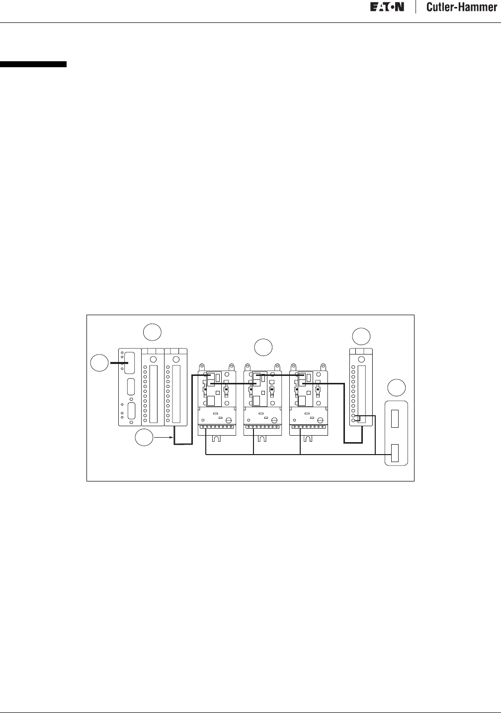
Typical Application
Figure 16 illustrates a typical D77A I/O module application this is integrated with a number of IT. starters with QSNAPs. In this
example, a D77A I/O is part of a larger system where motor control and I/O are required within a single panel. On the same QCPort
connection, both the I/O and the motor control are connected to a single network Adapter. The network adapter then represents the
D77A I/O and motor control as remote I/O, allowing for control and monitoring of the QCPort devices.
Figure 16: Panel Layout: Adapter, I/O and QSNAP
a) PC or PLC Connection
b) I/O Modules
c) QCPort Connection
d) IT. Starters with QSNAPs
e ) Po w e r Ta p / Te rm i n a to r R e s i s t o r
f) 24 V DC Power Supply
D77A-003
a
c
b
de
f
Intelligent Technologies (IT.) D77A I/O Module Products
MN05002001E For more information visit: www.EatonElectrical.com 23
I/O Function
Discrete Input Modules
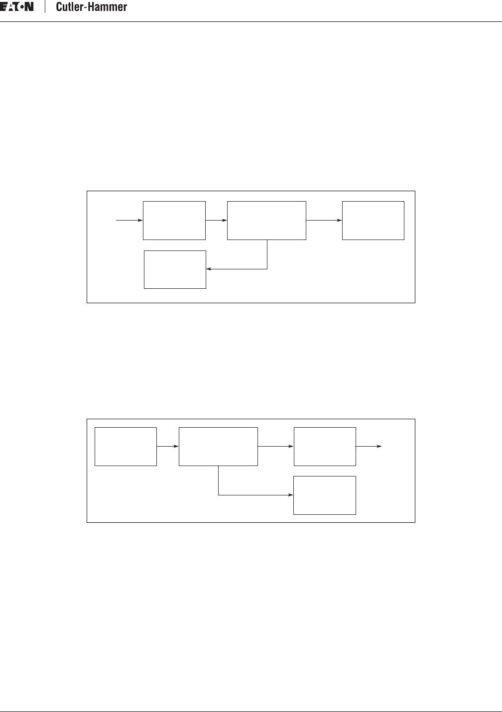
Figure 17 illustrates the basic signal processing operation. When a signal is present at the input point, the module responds with the
following sequence:
1. Optical Isolation — Optical isolation protects the I/O circuits and communication circuits from possible damage due to
transients and over-voltage.
2. Debounce Logic/Control — A debounce circuit and software limits the effects of transients and electrical noise by requiring the
input to be true for a certain period of time before the logic acknowledges a true signal. Once a true signal is achieved, the logic
turns on the LED.
3. QCPort Com./Logic — The logic updates the QCPort communication on a regular, scheduled basis as to the status of the input
point.
Figure 17: Discrete Input Module Operation
Discrete Output Modules
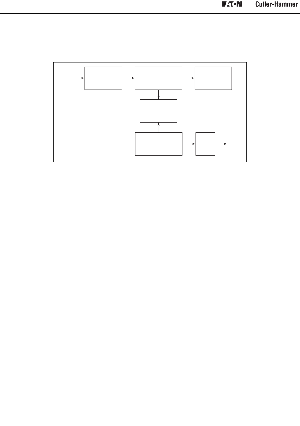
Figure 18 illustrates the basic logic processing operation. When the processor activates an output point, the module responds with
the following sequence:
1. QCPort Com./Logic — QCPort communication updates the logic circuit on a regular, scheduled basis as to the status of the
output points.
2. Optical Isolation — Optical isolation protects the I/O circuits and communication circuits from possible damage due to
transients and over-voltage. Once an active signal is transmitted to the optical isolation circuit, the LED is forward-biased.
3. Output Drivers — The driver activates the output point.
Figure 18: Discrete Output Module Operation
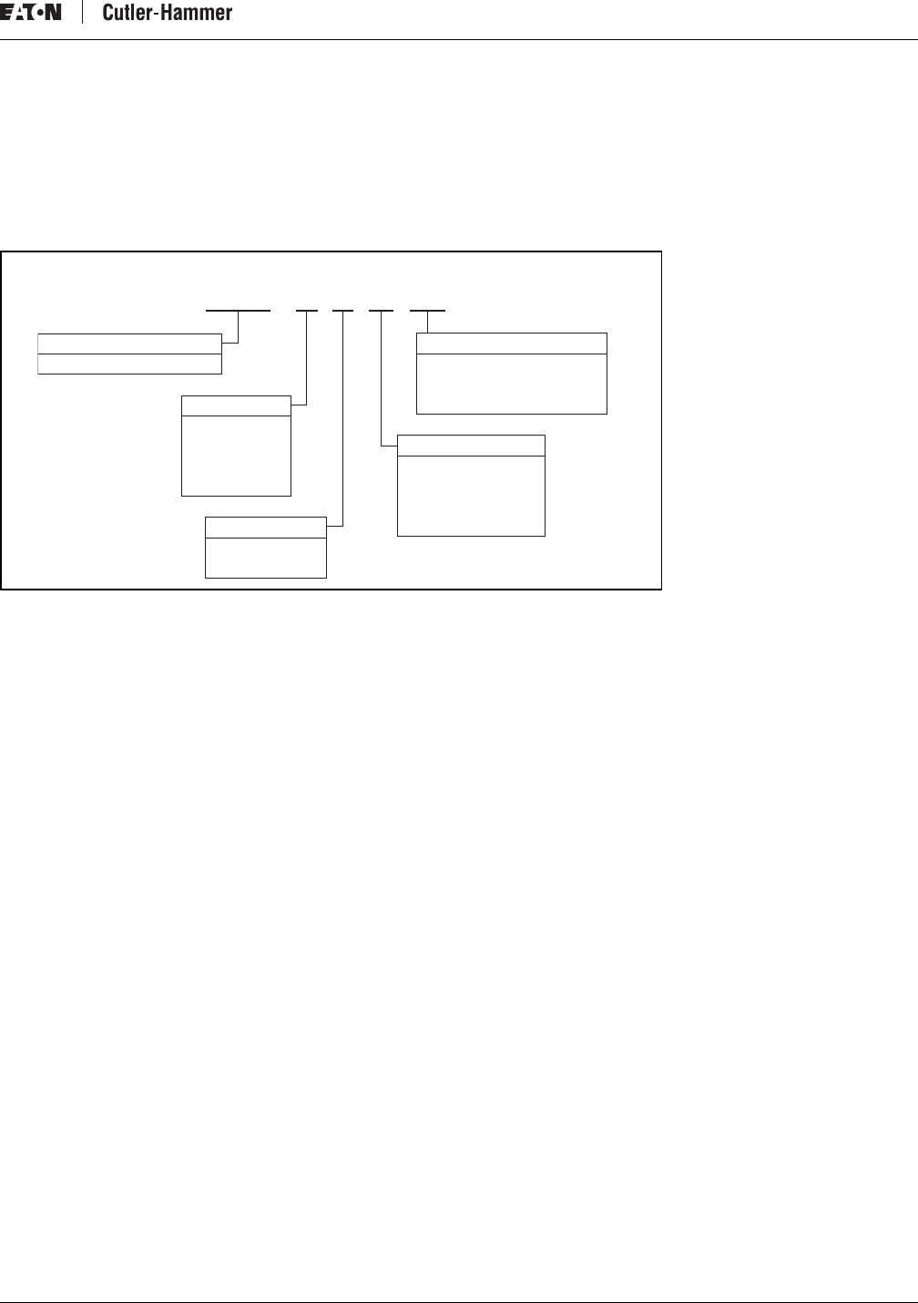
D77A-004
Optical
Isolation
Input Debounce
Logic/Control
QCPort
Com.
LED
Indication
D77A-005
QCPort
Com.
Optical
Isolation
Output
Drivers
LED
Indication
Output
Intelligent Technologies (IT.) D77A I/O Module Products
24 For more information visit: www.EatonElectrical.com MN05002001E
Discrete Combination Modules
Combination modules have the properties of both input and output points in a single module. The behavior of the combination
module’s input and output points are the same as those found in discrete input and output modules.
Figure 19: Discrete Combination Module Operation
D77A-032
Optical
Isolation
Input Debounce
Logic/Control
Optical Isolation Output
Drivers
LED
Indication
Output
QCPort
Comm
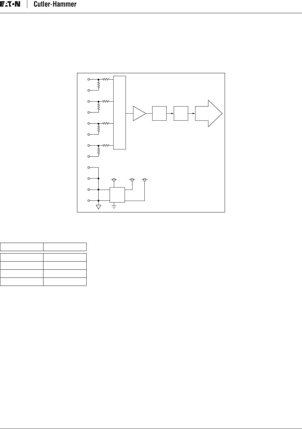
Intelligent Technologies (IT.) D77A I/O Module Products
MN05002001E For more information visit: www.EatonElectrical.com 25
Analog Input Modules
Figure 20 illustrates the basic signal processing operation. Analog signals from four separate channels are received by a multiplexer
(MUX). The MUX sequentially transfers this data to an analog-to-digital converter (ADC). The ADC measures the analog signal and
converts it to a digital value. This digital value is presented to the controller’s central processes unit (CPU). This data is then presented
to the QCPort for external processing.
Figure 20: Analog Input Module Operation
Analog input signal delays are associated with multiplexer switching, channel updating and channel reconfiguration. These delays are
all influenced by analog input filter frequency selection.
Table 24: Analog Input Signal Delays
Filter Setting Total Update Time
50 Hz 336 ms
60Hz 283.2 ms
250 Hz 80 ms
500 Hz 44 ms
M
U
X
V0
I0
I1
V1
I2
V2
I3
C0
C1
C2
C3
V3
ADC CPU QC Port
V1+V2-V2
SCHEM-001
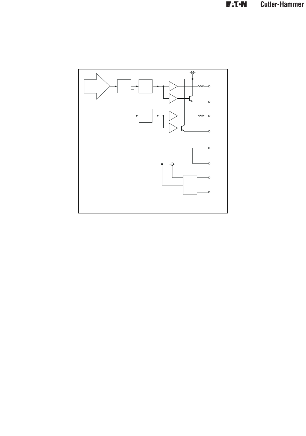
Intelligent Technologies (IT.) D77A I/O Module Products
26 For more information visit: www.EatonElectrical.com MN05002001E
Analog Output Modules
Figure 21 illustrates the basic signal processing operation. Digital data from external sources are extracted from the QCPort and
transferred to the controller’s central processor unit (CPU). The digital data from the CPU is transferred to the digital-to-analog
converters (DAC). The DAC system converts the digital values to linear signals and provides them to the output terminals.
Figure 21: Analog Output Module Operation
V0
I0
QC Port CPU DAC
SCHEM-002
V1
I1
DAC
P. S .
C0
C1
+24V
G
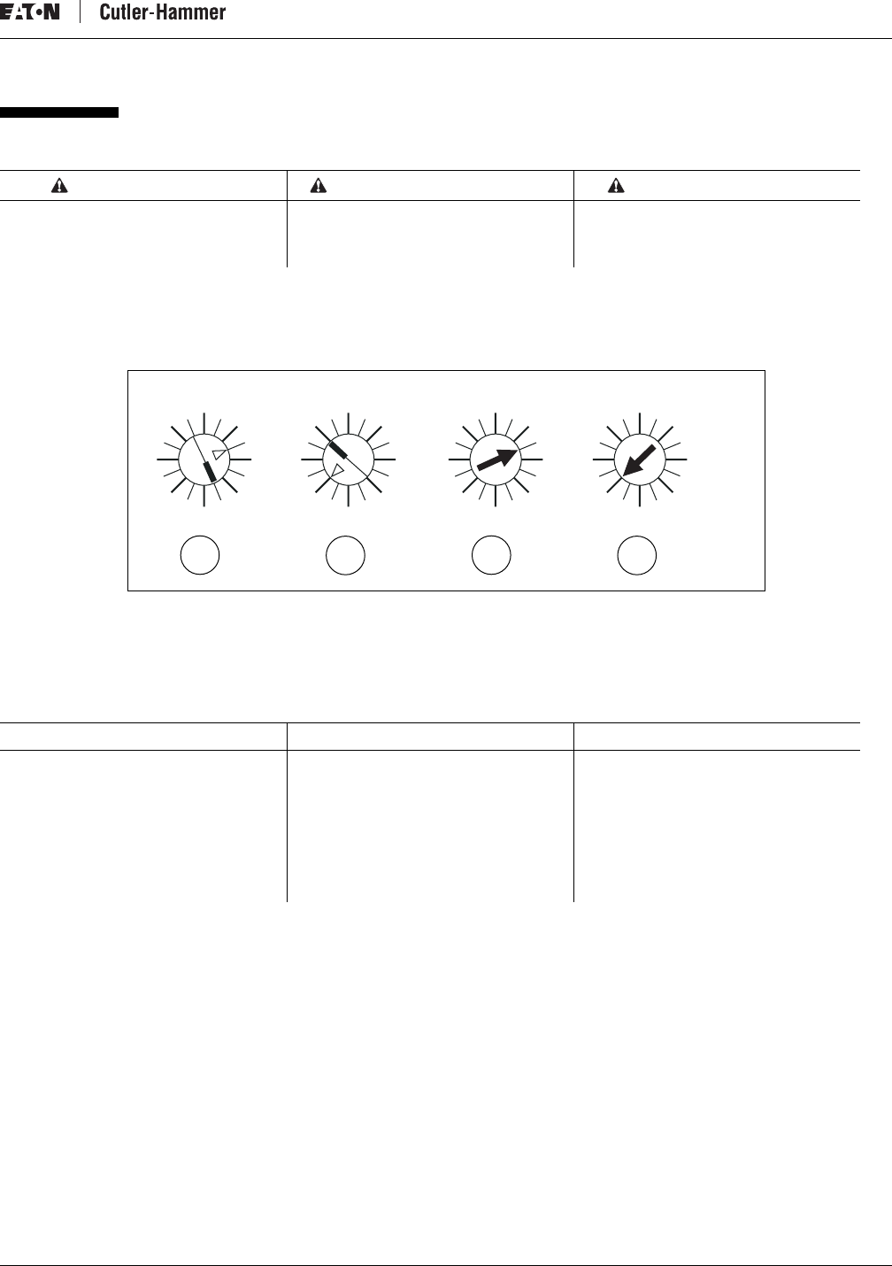
Intelligent Technologies (IT.) D77A I/O Module Products
MN05002001E For more information visit: www.EatonElectrical.com 27
Installation
Setting Group ID
A unique Group ID must be assigned to each module. The modules are shipped with a factory-set default setting of zero.
To set the Group ID, use a screwdriver to rotate the rotary switch located on the top of the module.
Figure 22: Group ID Switch
a) Discrete I/O Group ID Three
b) Discrete I/O Group ID Ten
c) Analog I/O Group ID Three
d) Analog I/O Group ID Ten
DIN rail installation requires one of two procedures:
•DIN Rail installation without Backplane
•DIN Rail installation with Backplane
WARNING AVERTISSEMENT ADVERTENCIA
Indicates a potentially hazardous situation
which, if not avoided, can result in serious
injury or death.
Indique une situation potentiellement
dangereuse qui, si elle n’est pas évitée, peut
entraîner de graves blessures, voire la mort.
Indica que existe una situación
potencialmente peligrosa, que si no es
evitada, podrá resultar en serias heridas
corporales o en la muerte.
Notice Avis Aviso
In the examples above, the left module has a
Group ID of 3 and the right a Group ID of 10.
The arrow indicates the Group ID setting
(not the line). Refer to the IT. QCPort System
Install and Planning Guide (Publication No.
MN05001002E) for more information on
setting the Group ID.
Dans les exemples ci-dessus, le module de
gauche porte un numéro d’identification de
groupe n° 3 et celui de droite un de 10. La
flèche indique le réglage du numéro
d’identification de groupe (non pas la ligne).
Reportez-vous au Guide de planification et
d’installation du système bâbord IT. QCPort
(publication no. MN05001002E) pour plus
d’information sur les réglages du numéro
d’identification de groupe.
En los ejemplos de arriba, el módulo
izquierdo tiene una identificación de Grupo
3 y el de la derecha una identificación de
Grupo 10. La fecha indica la configuración de
identificación de Grupo (no la línea).
Refiérase a la Guía de Planificación e
Instalación del Sistema QCPort del IT. (
Publicación No. MN05001002E) para obtener
más información de cómo configurar la
identificación de Grupo.
0
8
2
14
412
6
10
0
8
2
14
412
6
10
0
8
2
14
412
6
10
0
8
2
14
412
6
10
D77A-015
abcd
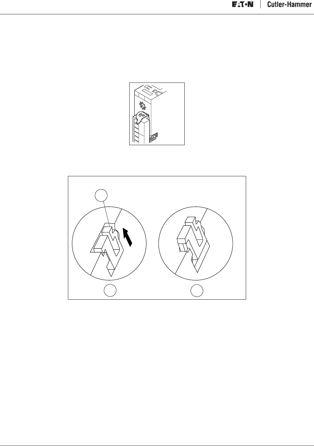
Intelligent Technologies (IT.) D77A I/O Module Products
28 For more information visit: www.EatonElectrical.com MN05002001E
Installation Without Backplane
Module Preparation
The DIN rail locking tab is located under the removable terminal on the front of the device. Remove the terminal to gain access to the
locking tab.
1. Remove the terminal by unlocking the terminal tabs.
Figure 23: Removable Terminal Locking Tabs
2. Remove the terminal strip from the module.
3. Insert a screwdriver under the DIN rail locking tab and lift up to unlock the locking tab.
Figure 24: Unlock DIN Rail Locking Tab
a) Tab
b) Locking Tab Captured
c) Locking Tab Released
D77A-016
0
8
2
14
412
6
10
c
b
a
D77A-017
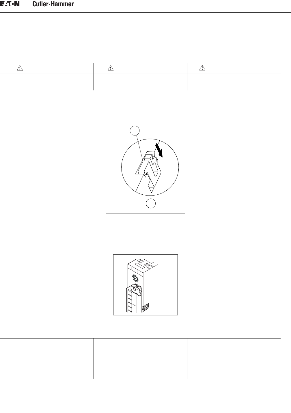
Intelligent Technologies (IT.) D77A I/O Module Products
MN05002001E For more information visit: www.EatonElectrical.com 29
Installing the Module
The module is now ready for installation on the DIN rail.
1. The module must always be inserted perpendicular onto the DIN rail. Push the module straight back onto the DIN rail.
2. Depress the locking tab to secure the module to the DIN rail.
Figure 25: Lock DIN Rail Locking Tab
a) Locking Tab
b) Locking Tab Captured
3. Install the terminal strip on the front of the module.
4. Lock the terminal strip into place using the locking tabs.
Figure 26: Removable Terminal Locking Tab
CAUTION PRÉCAUTION PRECAUCIÓN
Do no “rock” the module onto the DIN rail.
The rocking action could damage the
module.
Ne « basculez » pas le module sur le rail DIN.
L’action de basculement pourrait
endommager le module.
No “meza” el módulo sobre el riel DIN. El
mecerlo podrá dañar el módulo.
Notice Avis Aviso
After the strip is installed, install
interconnects; see the IT. QCPort System
Install and Planning Guide (Publication No.
MN05001002E) for more information.
Après avoir installé la bande, installez les
interconnecteurs ; voyez le Guide de
planification et d’installation du système
bâbord IT. QCPort (publication no.
MN05001002E) pour plus d’information.
Después de instalada la banda, instale los
interconectadores, vea la Guía de
Planificación e Instalación del Sistema
QCPort del IT. ( Publicación No.
MN05001002E) para obtener más
información.
b
a
D77A-018
D77A-019
0
8
2
14
412
6
10
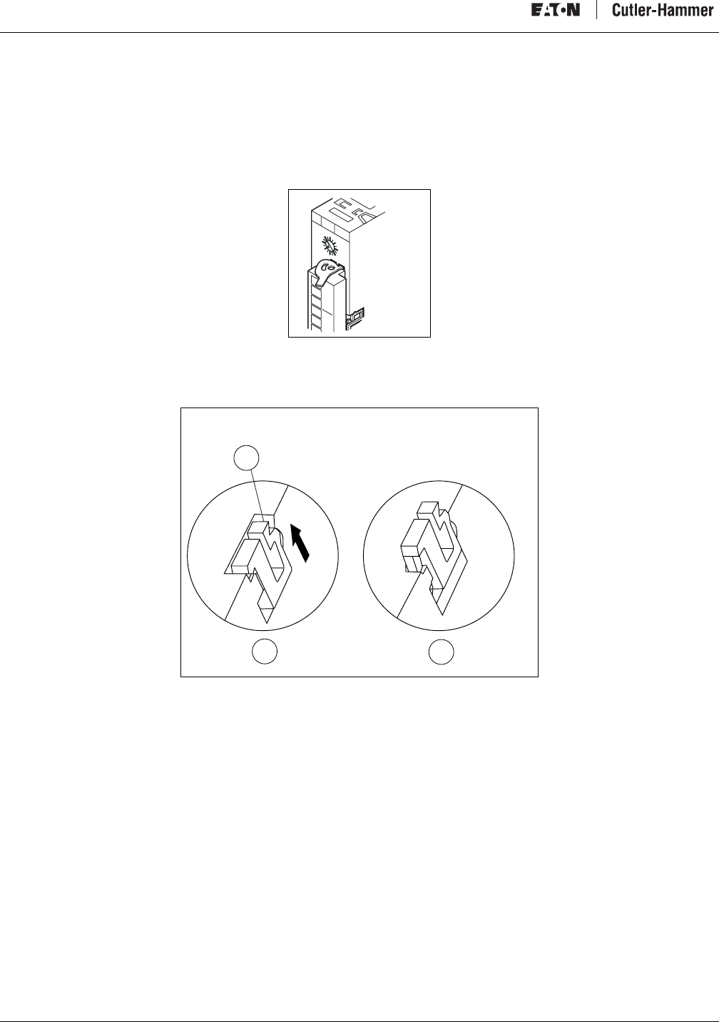
Intelligent Technologies (IT.) D77A I/O Module Products
30 For more information visit: www.EatonElectrical.com MN05002001E
Installation With Backplane
Module Preparation
The DIN rail locking tab is underneath the removable terminal (on the front of the device). The terminal must be removed to gain
access to the locking tab.
1. To remove the terminal, unlock the terminal tabs.
Figure 27: Removable Terminal Locking Tabs
2. Remove the terminal strip from the module.
3. Insert a screwdriver under the DIN rail locking tab and lift up to unlock the locking tab.
Figure 28: Unlock DIN Rail Locking Tab
a) Tab
b) Locking Tab Captured
c) Locking Tab Released
D77A-016
0
8
2
14
412
6
10
c
b
a
D77A-017
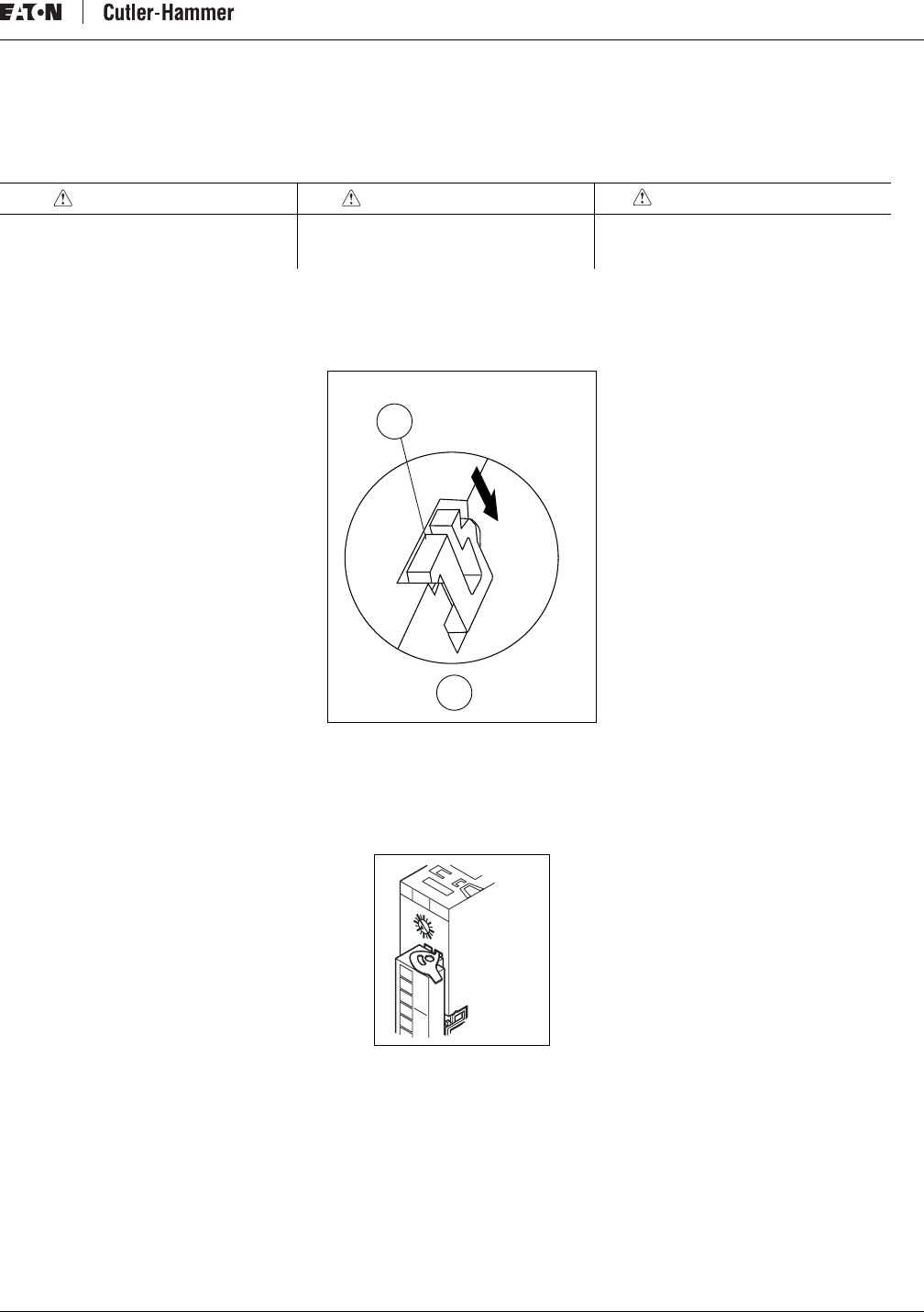
Intelligent Technologies (IT.) D77A I/O Module Products
MN05002001E For more information visit: www.EatonElectrical.com 31
Installing the Module
The module is now ready for installation on the DIN rail.
1. Line the center of the module up with the backplane connector on the DIN rail. Ensure the backplane connector is installed with
the arrows up. The module must always be inserted perpendicular onto the DIN rail.
2. Push the module straight back onto the DIN rail and backplane connector.
3. Depress the locking tab to secure the module to the DIN rail.
Figure 29: Lock DIN Rail Locking Tab
a) Locking Tab
b) Locking Tab Captured
4. Install the terminal strip on the front of the module.
5. Lock the terminal strip into place using the locking tabs.
Figure 30: Removable Terminal Locking Tab
CAUTION PRÉCAUTION PRECAUCIÓN
Do not “rock” the module onto the DIN rail.
The rocking action could damage the
module.
Ne « basculez » pas le module sur le rail DIN.
L’action de basculement pourrait
endommager le module.
No “meza” el módulo sobre el riel DIN. El
mecerlo podrá dañar el módulo.
b
a
D77A-018
D77A-019
0
8
2
14
412
6
10
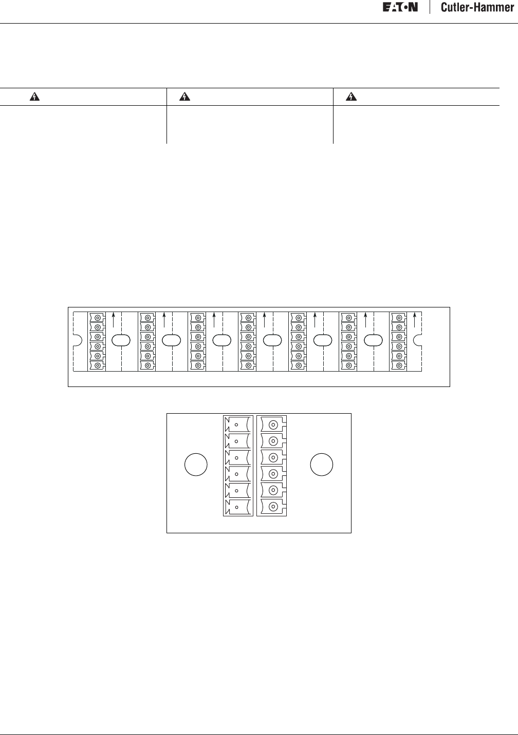
Intelligent Technologies (IT.) D77A I/O Module Products
32 For more information visit: www.EatonElectrical.com MN05002001E
QCPort Connections
Interconnects/Connections
Connecting the I/O modules together and to other IT. family products involves using one or more of the interconnect connectors. The
I/O product family uses two types of connectors:
•The backplane interconnect
•The short run interconnect
These interconnects provide the I/O module with power and communications.
For more information on making interconnects, the use of interconnects and the restrictions placed upon interconnects, refer to the IT.
QCPort System Install and Planning Guide (Publication No. MN05001002E).
QCPort Backplane Interconnect
The QCPort backplane interconnect is used when connecting the Adapter and I/O modules on a DIN rail. The interconnect fits inside
the channel of the DIN rail and provides for connection to power and communication to the Adapter and I/O products (Figure 31 and
Figure 32).
Figure 31: QCPort Backplane Interconnect
Figure 32: QCPort Interconnect Backplane Connectors
a) Module Side
b) Backplane Side
WARNING AVERTISSEMENT ADVERTENCIA
Hazardous voltage can cause electric shock
and burns. Always disconnect power before
proceeding with any work on this product.
La tension dangereuse peut causer des
électrochocs et des brûlures. Coupez
toujours le courant avant d’entreprendre
tout travail sur ce produit.
Los voltajes peligrosos pueden causar
electrochoque y quemaduras. Siempre
desconecte la energía antes de proceder con
cualquier trabajo en este producto.
6
GND
B
A
+24
1
D77A-020
6
GND
B
A
+24
1
D77A-021
a b
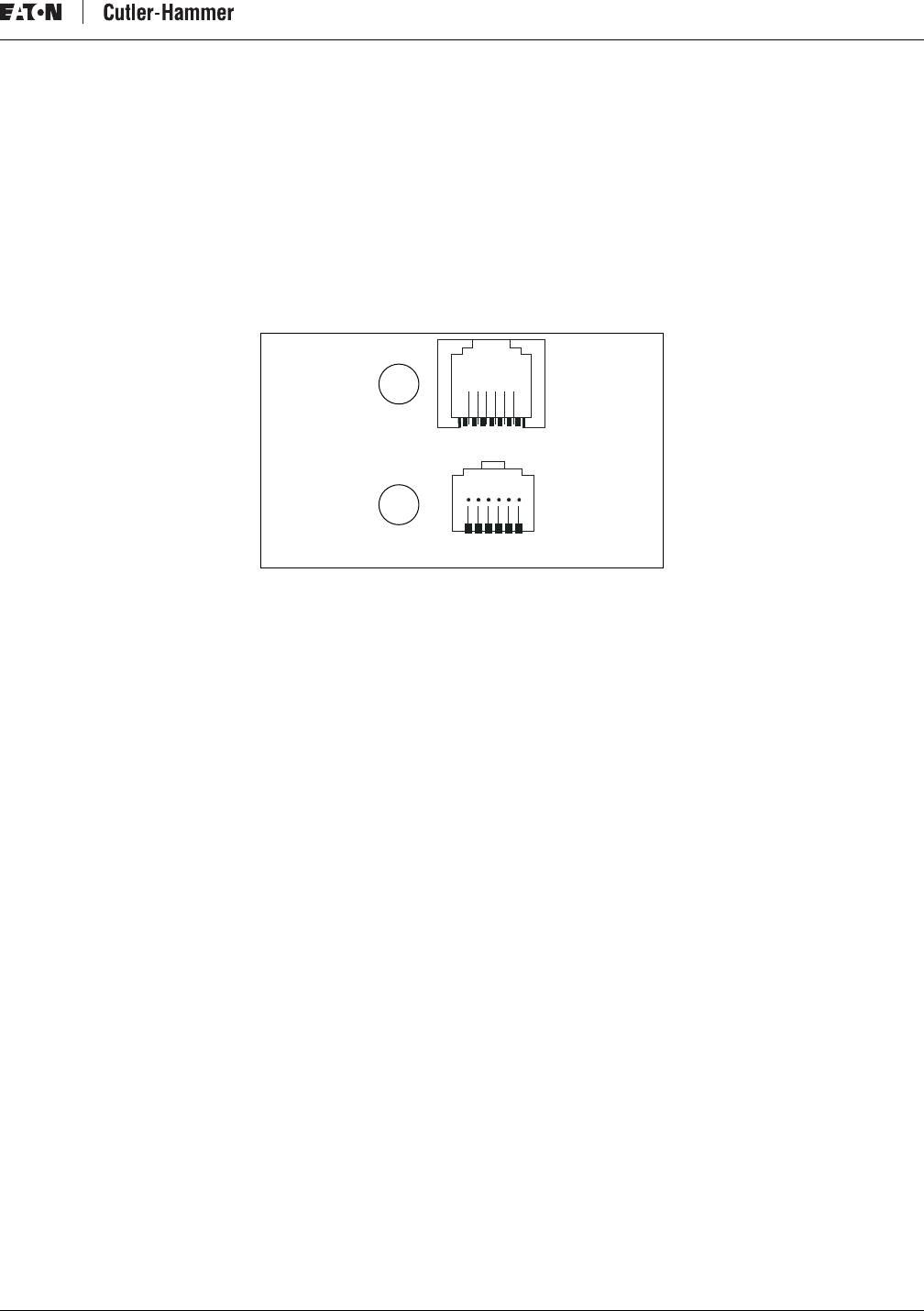
Intelligent Technologies (IT.) D77A I/O Module Products
MN05002001E For more information visit: www.EatonElectrical.com 33
Pre-manufactured QCPort Interconnect Cables
To connect the D77A I/O modules together without using a QCPort backplane, use the QCPort connectors that are located at the bottom
of the D77A I/O module. There are two QCPort connections next to each other. They are configured parallel with each other so that
they can be daisy chained together using QCPort Interconnect cables. There are standard sizes for the QCPort Interconnect cables.
These sizes are listed in the “Renewal Parts” portion of “Troubleshooting and Maintenance.”
Note: The maximum current allowed through a QCPort interconnect cable is 1 Amp. The maximum number of modules that may be
daisy chained together using QCPort interconnect cables is calculated by adding the current rating of each device and keeping
the total less than 1 Amp.
When making this interconnect, refer to the IT. QCPort System Install and Planning Guide (Publication No. MN05001002E) for the
recommended cable and connections.
Figure 33: QCPort Connector
a) Connector Half
b) Keyed Insert
1 – +24
2 – GND
3 – B
4 – A
5 – +24
6 – GND
1
1
a
b
D77A-022
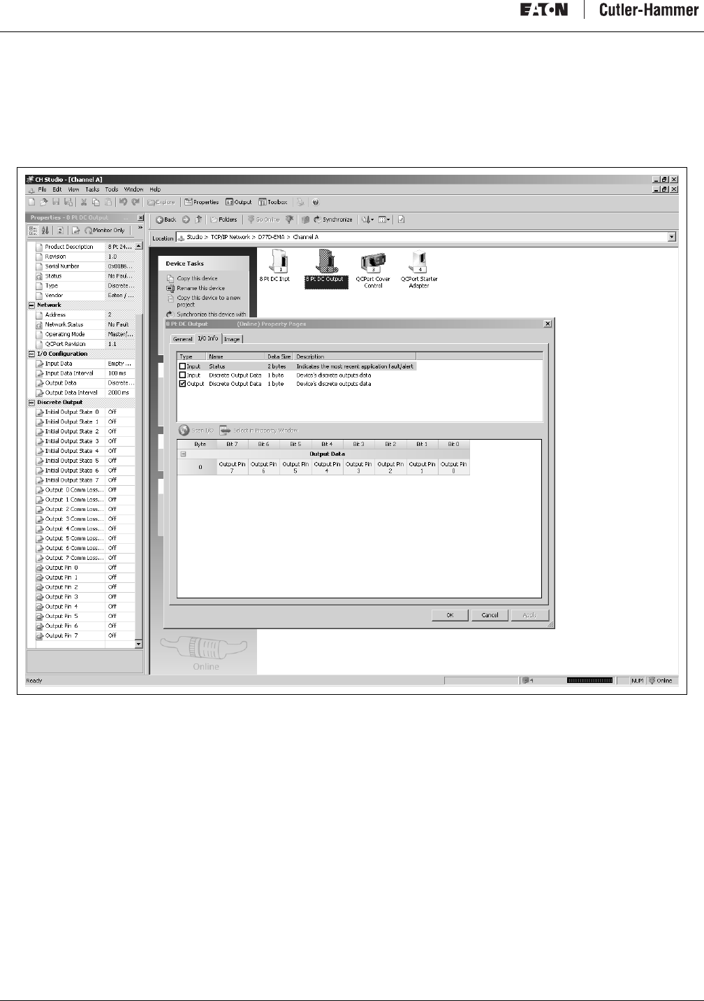
Intelligent Technologies (IT.) D77A I/O Module Products
34 For more information visit: www.EatonElectrical.com MN05002001E
Configuration
There are parameters associated with the D77A I/O products that can be set using a software tool such as CH Studio for enhanced
functionality.
All of the enhanced features are selectable through CH Studio either in the Property Window or the Property Pages of the device.
Figure 34: I/O Property Page
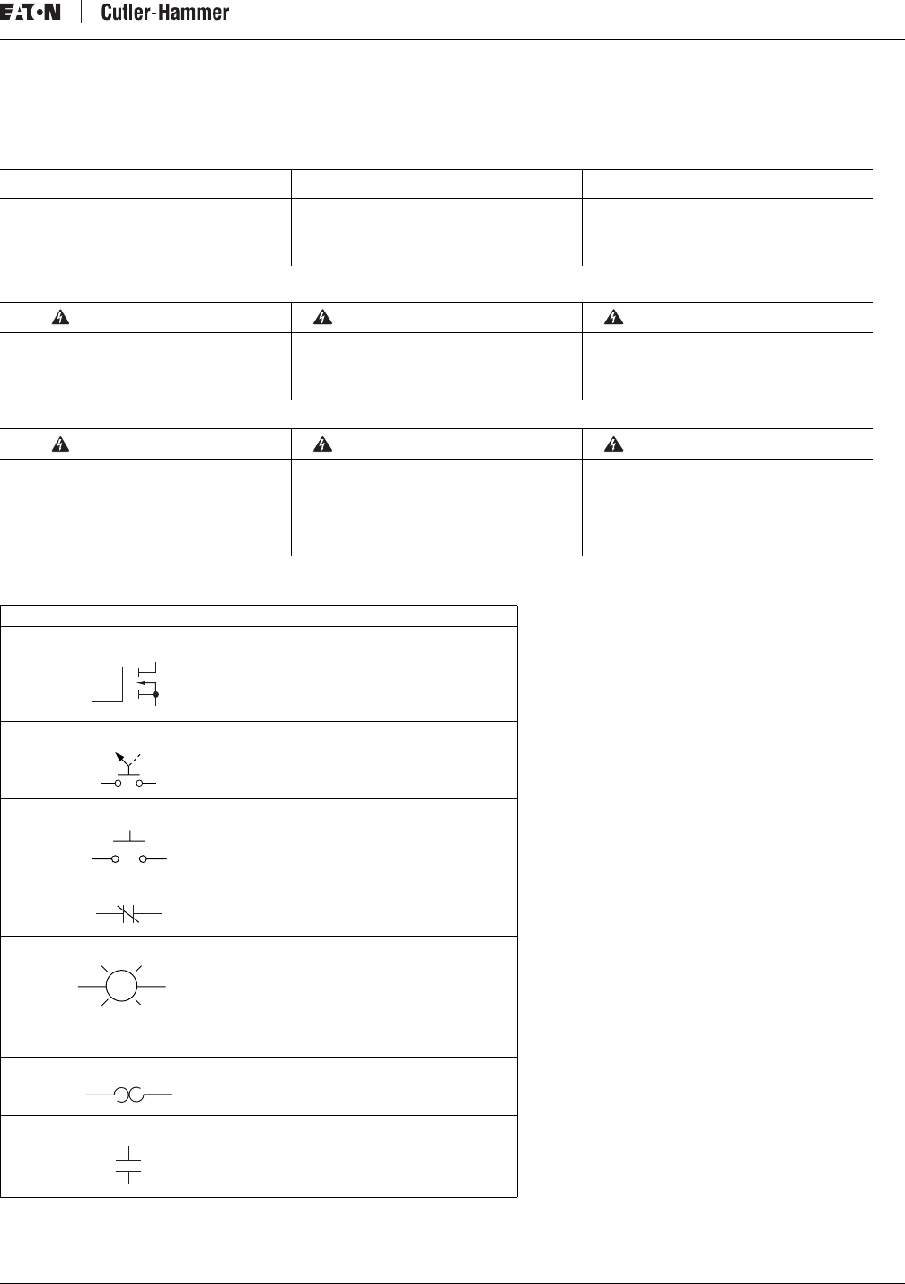
Intelligent Technologies (IT.) D77A I/O Module Products
MN05002001E For more information visit: www.EatonElectrical.com 35
Field Wiring
Table 25: Symbol Definitions
Notice Avis Aviso
Install all field wiring on the modules in
compliance with all applicable regularity
codes.
Installez tout le câblage de terrain sur les
modules en accord avec tous les codes de
réglementation applicables.
Instale todo el cableado del inductor en los
módulos cumpliendo con todos los códigos
de regularidad que apliquen.
WARNING AVERTISSEMENT ADVERTENCIA
Hazardous voltage can cause electric shock
and burns. Always disconnect power before
proceeding with any work on this product.
La tension dangereuse peut causer des
électrochocs et des brûlures. Coupez
toujours le courant avant d’entreprendre
tout travail sur ce produit.
Los voltajes peligrosos pueden causar
electrochoque y quemaduras. Siempre
desconecte la energía antes de proceder con
cualquier trabajo en este producto.
WARNING AVERTISSEMENT ADVERTENCIA
Only apply 24V DC to the I/O module power
terminals. Use of any other voltage may
result in personal injury, property damage
and damage to the IT. D77A I/O module.
N’appliquez que du courant continu de 24 V
aux bornes de courant des modules I/O.
L’emploi de toute autre tension peut
entraîner des blessures corporelles, des
dégâts matériels et des dégâts au module
IT. D77A I/O.
Sólo aplique 24V CD a los terminales de
energía del módulo I/O. El uso de cualquier
otro voltaje podrá resultar en heridas
corporales, daños a la propiedad o daños al
IT. Módulo I/O D77A.
Symbol Definition
MOSFET
Selector Switch
Push Button
Contact (normally closed)
Pilot Light
Overload
Capacitor
GS
D
G
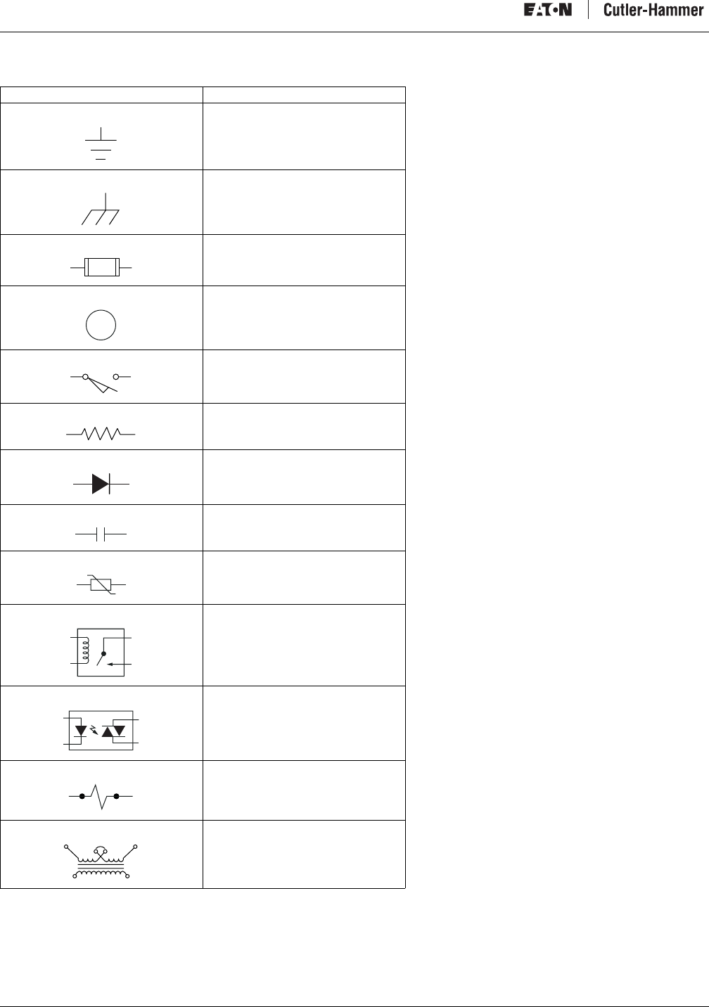
Intelligent Technologies (IT.) D77A I/O Module Products
36 For more information visit: www.EatonElectrical.com MN05002001E
Earth Ground
Chassis Ground
Fuse
Control Relay
Limit Switch
Resistor
Diode
Contact (normally open)
MOV
Relay Module Output Point
Optical Isolator AC Output Point
Solenoid
Control Transformer
Symbol Definition
CR
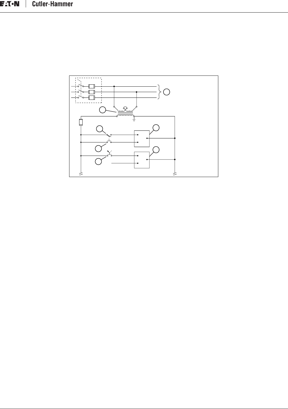
Intelligent Technologies (IT.) D77A I/O Module Products
MN05002001E For more information visit: www.EatonElectrical.com 37
AC Inputs
AC power is typically used to energize loads related to machinery function such as solenoid valves and motor starters. The same AC
power source is often used as signal power for inputs as illustrated in Figure 35. The input devices to which AC inputs are wired are
typically two-lead devices like push buttons, limit switches and selector switches. One side of the input device is wired to an AC power
source while the other is wired to the input terminal. Another input terminal is wired to a grounded neutral wire. Refer to AC Output
Module Specifications on page 13 for module details.
Figure 35: AC Input Wiring
a) Three-phase Motor Circuits
b) First Point of Input Module
c) Second Point of Module
d) Selector Switch
e) Push Button
f) Limit Switch
g) Control Transformer
f
g
a
b
c
d
e
L1 1FU
L2
X1 X2
0
C0
C1
1
2
3
2FU
L3
10FU
L1 L2
N/C
3FU
H1 H4
H3 H2
JIC-0002
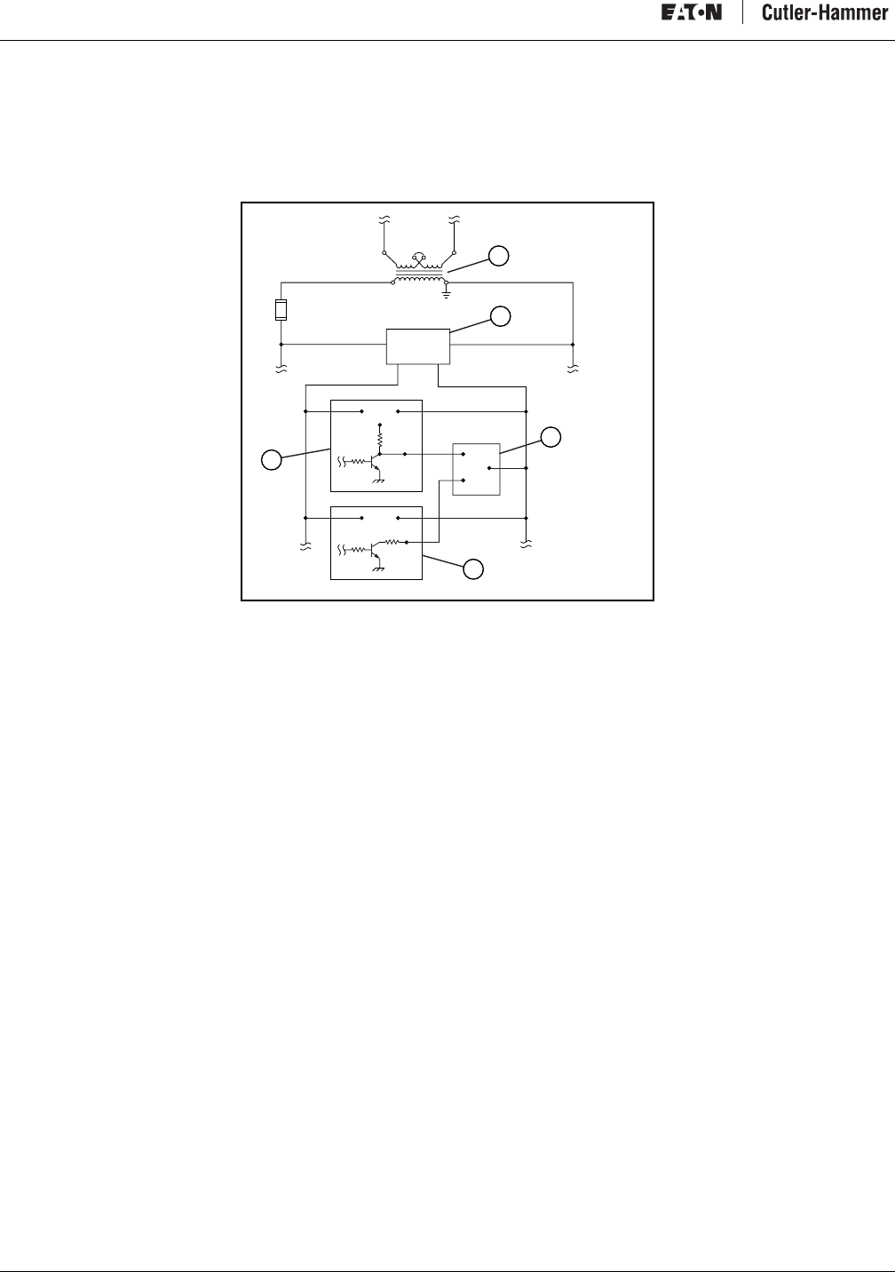
Intelligent Technologies (IT.) D77A I/O Module Products
38 For more information visit: www.EatonElectrical.com MN05002001E
DC Inputs
DC Input modules are designed to operate with either sinking or sourcing devices. They are typically used with proximity sensors and
other solid-state devices. (Figure 36) Input modules may need to be installed relatively close to the sensor location. Refer to DC Input
Module Specifications on page 9 for module details.
Figure 36: DC Input Wiring
a) Control Transformer
b) 24 VDC Power Supply
c) DC Input Module
d) Sinking Input Device
e) DC Sourcing Device
H1 H4
H3 H2
24VDC
10FU
C0
0
1
X1 X2
120VAC NEU
-
-
-
+
+
+
JIC-0007
a
b
c
d
e
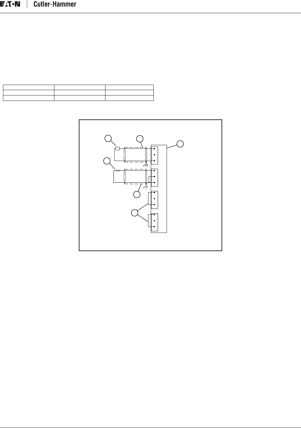
Intelligent Technologies (IT.) D77A I/O Module Products
MN05002001E For more information visit: www.EatonElectrical.com 39
Analog Inputs
Analog signals are typically used to transmit or indicate linear data like temperature, pressure or flow, as illustrated in Figure 37. The
analog input devices to which analog inputs are wired are typically current loop or voltage range devices like 4-20 mA transmitters or
0-10V transmitters. Refer to Analog Input Module Specifications on page 10 for module details.
Note: Ground the shield on one end only. It is recommended to limit the cable impedance by keeping the cable length as short as
possible. Limiting the distance from ground to the shield is also recommended. The recommended cable is a BeldenTM 8761 or
equivalent.
Note: When an input channel in not used, jumper from V to C eliminating noise from causing erroneous readings for that channel.
Figure 37: Analog Input Wiring
a) Input Module
b) Jumper
c) Shield (Ground One End Only)
d) Current Input Device
e) Voltage Input Device
f) Shield (Ground One End Only)
Wire Type Wire Size Terminal Torque
Solid Cu-90°C #14 - # 22 AWG 4.5 in-lbs
Stranded Cu-90°C #16 - # 22 AWG 4.5 in-lbs
1
2
3
4
5
6
7
8
I0
C0
V1
I1
C1
V2
I2
C2
V3
I3
C3
9
10
11
12
-+
JIC-0012
V0
I
V
a
c
d
ef
b
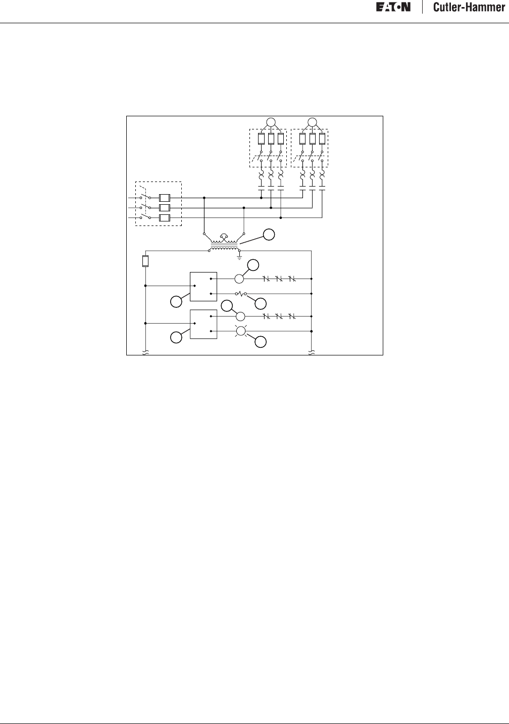
Intelligent Technologies (IT.) D77A I/O Module Products
40 For more information visit: www.EatonElectrical.com MN05002001E
AC Outputs
AC power is typically used to energize loads related to machinery function such as solenoid valves and motor starters. These devices
are generally two-lead devices as illustrated in Figure 38. One side is wired to a grounded neutral wire while the other is wired to the
output terminal. Refer to AC Output Module Specifications on page 13 for module details.
Figure 38: AC Output Wiring
a) Control Transformer
b) M1 Motor Starter Coil
c) Solenoid Valve
d) M2 Motor Starter Coil
e) Pilot Light
f) Second Point of Module
g) First Point of Module
d
a
b
c
e
f
g
L1 1FU
L2 2FU
L3
L1 L2
3FU
H1 H4
M1 M2
M1 M2
OLDS
JIC-0001
OLDS
OLDS
SOL1
OLDS
H3 H2
4FU
5FU
6FU
7FU
8FU
9FU
PL1
G
M1
C0
10FU
0
1
C1 2
3
X1 X2
M2
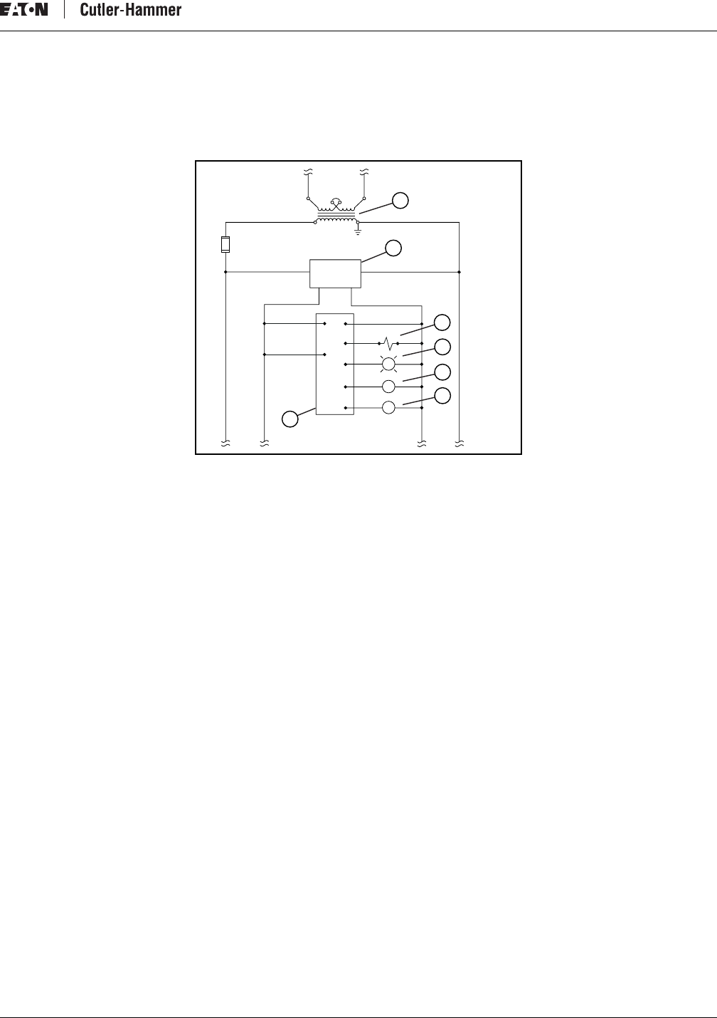
Intelligent Technologies (IT.) D77A I/O Module Products
MN05002001E For more information visit: www.EatonElectrical.com 41
DC Outputs
DC power is typically used for instrumentation or light control circuits. Examples might be solenoid valves, indicator lamps or sinking
or sourcing signals to other equipment. These devices are generally two-lead devices as illustrated in Figure 39. Refer to DC Output
Module Specifications on page 14 for module details.
Figure 39: DC Output Wiring
a) Control Transformer
b) 24 VDC Power Supply
c) Solenoid
d) Pilot Light
e) Control Relay 1
f) Control Relay 2
g) DC Output Module Points 2 and 3
h) DC Output Module Points 0 and 1
H1 H4
H3 H2
24VDC
10FU
X1 X2
120VAC NEU
-
-
+
+
JIC-0015
G
CR
CR
C0
0
1
2
3
SOL1
PL1
a
c
b
d
e
f
g
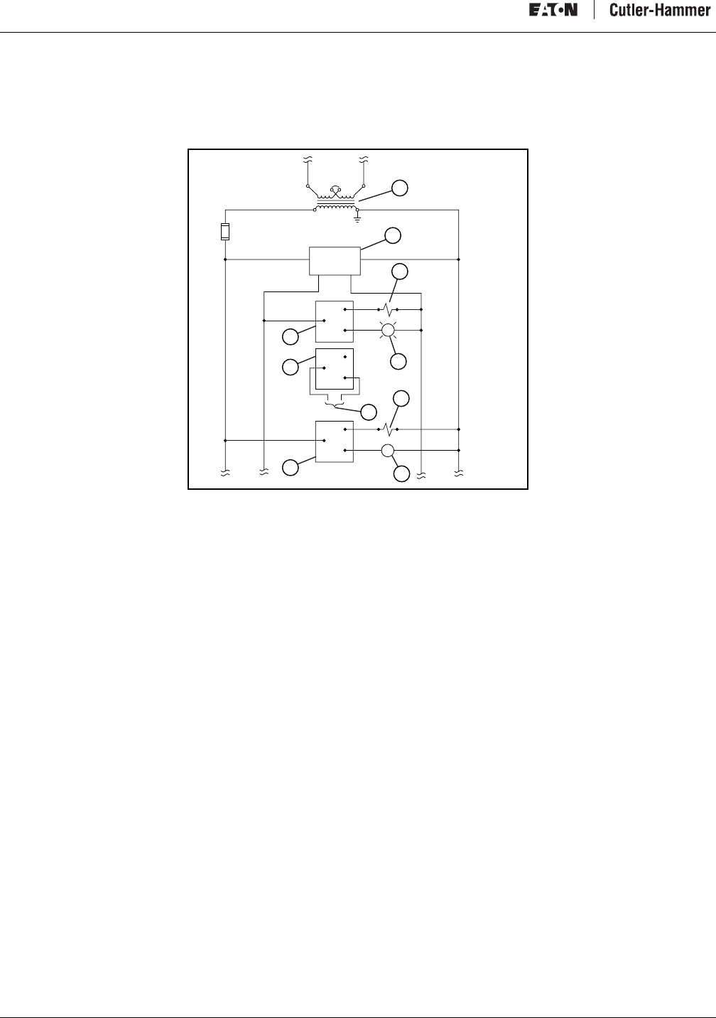
Intelligent Technologies (IT.) D77A I/O Module Products
42 For more information visit: www.EatonElectrical.com MN05002001E
Relay Outputs
Relay outputs can be used to control a variety of different loads. They can be used in AC or DC circuits or they can be used to provide
a dry contact to other equipment. (Figure 40) Refer to Relay Output Module Specifications on page 15 for module details.
Figure 40: Relay Output Wiring
a) Control Transformer
b) 24 VDC Power Supply
c) DC Solenoid
d) DC Pilot Light
e) AC Solenoid
f) Dry Contact to Other Equipment
g) AC Control Relay
h) Relay Output Points 4 and 5
i) Relay Output Points 2 and 3
j) Relay Output Points 0 and 1
H1 H4
H3 H2
24VDC
10FU
X1 X2
120VAC NEU
-
+
JIC-0011
G
CR
C0
C1
C2
0
1
2
3
4
5
SOL1
SOL2
PL1
a
c
b
d
e
f
g
h
i
j
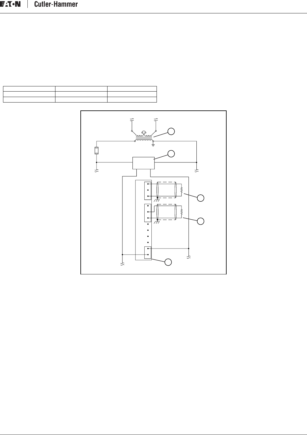
Intelligent Technologies (IT.) D77A I/O Module Products
MN05002001E For more information visit: www.EatonElectrical.com 43
Analog Outputs
Analog signals are typically used to transmit or indicate linear data like pressure or linear actuation, as illustrated in Figure 41. The
analog output devices to which analog outputs are wired are typically current loop or voltage range devices like 4-20 mA signals or
0-10V signals. Refer to Analog Output Module Specifications on page 16 for module details.
Note: Ground the shield on one end only. It is recommended to limit the cable impedance by keeping the cable length as short as
possible. Limiting the distance from ground to the shield is also recommended. The recommended cable is a BeldenTM 8761 or
equivalent.
Figure 41: Analog Output Wiring
a) Control Transformer
b) 24 VDC Power Supply
c) Voltage Output Device
d) Current Output Device
Wire Type Wire Size Terminal Torque
Solid Cu-90°C #14 - # 22 AWG 4.5 in-lbs.
Stranded Cu-90°C #16 - # 22 AWG 4.5 in-lbs.
H1 H4
H3 H2
24VDC
10FU
1
2
3
4
5
6
7
8
I0
C0
V1
I1
C1
NC
NC
9
10
11
12
-
X1 X2
120VAC NEU
+
-
+
JIC-0008
NC
NC
V0
V
I
a
b
c
d
e
-
+
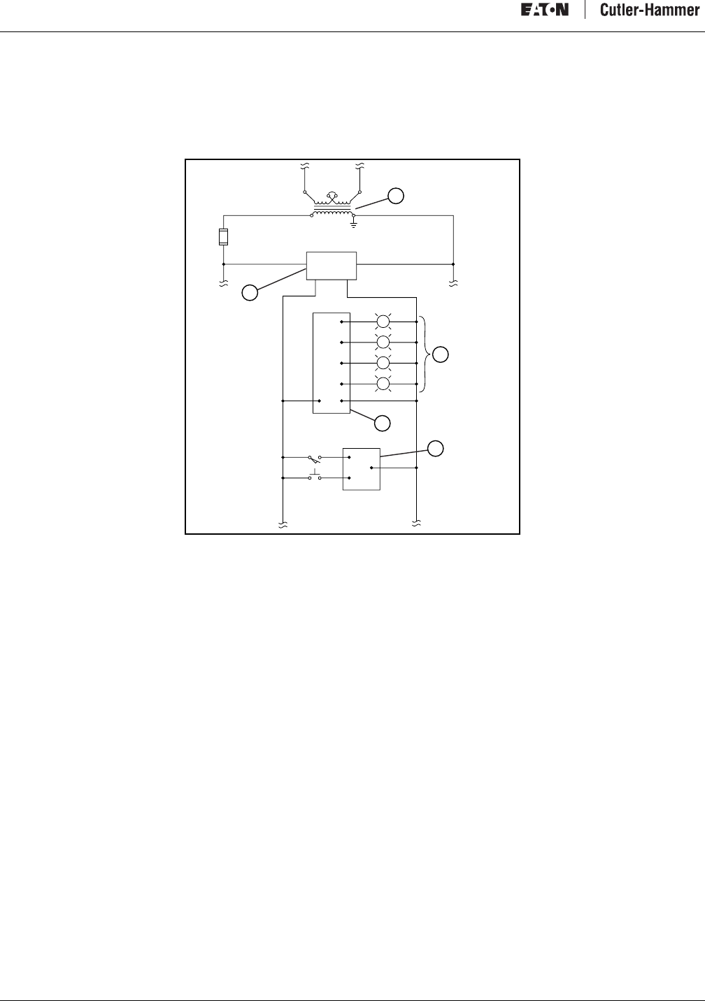
Intelligent Technologies (IT.) D77A I/O Module Products
44 For more information visit: www.EatonElectrical.com MN05002001E
Combination I/O
Combination I/O modules incorporate the features of input points and output points into a single module. Figure 42 illustrates a
typical dual purpose module application. The advantage is improved I/O density and greater flexibility for many applications. Refer to
Combination Module Specifications on page 18 for module details.
Figure 42: Combination I/O Wiring
a) Control Transformer
b) DC Loads
c) Output Points
d) Inputs
e) 24 VDC Power Supply
H1 H4
H3 H2
G
A
B
R
24VDC
10FU
0
1
0
C0
1
2
3
LS1
PB1
-
X1 X2
120VAC NEU
+
-
+
JIC-0003
PLT2
PLT3
PLT4
PLT1
a
e
c
d
b
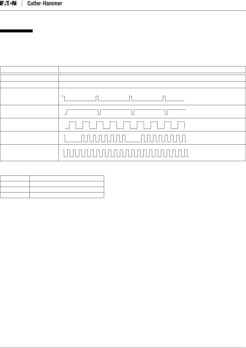
Intelligent Technologies (IT.) D77A I/O Module Products
MN05002001E For more information visit: www.EatonElectrical.com 45
Troubleshooting and Maintenance
Status LED
The status LED is located on the upper left of the D77A I/O module as pictured in Figure 1,
Module Component Location. The LED’s status changes depending on the state of the I/O module.
Table 26: Status LED
Fault Codes
Table 27: Analog 10 Fault Codes
State LED Behavior
No Power OFF
Power-Up Routine OFF – CRC corrupt
Off-Line, OK (mostly off)
On-Line (mostly on)
Faulted (50%)
Identify device (burst)
Undiscovered
0 x 41 (65) Analog input over range.
0 x 42 (66) Analog input under range.
0 x 44 (68) Analog input open.
0 x 45 (69) Analog input shorted.
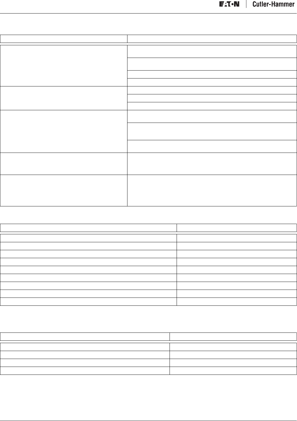
Intelligent Technologies (IT.) D77A I/O Module Products
46 For more information visit: www.EatonElectrical.com MN05002001E
Troubleshooting
Table 28: Troubleshooting
Renewal Parts
Table 29: I/O Module Renewal Parts
Communication Troubleshooting Hints
Explanation of LED Duty Cycle States
Table 30: Explanation of LED Duty Cycle States
Observation Possible Cause/Corrective Action
The input LED will not illuminate. Verify that the module is powered; the LED is controlled by the micro controller
in the device.
The power for the input itself may not be applied. Verify that there is a valid
signal on the input point.
The screws on the terminal may be loose; tighten the screws.
Replace the device.
The output LED is illuminated but the output is not on. Check that the switch closes on the output using a multi meter.
The screws on the terminal may be loose; tighten the screws.
Replace the device.
The status LED has a “fast blink” while all other device’s
status LEDs are “mostly on.” See Table 26 Status LED. The “fast blink” device may have the same Group ID as another device. Verify
that all devices have unique Group IDs.
The “fast blink” device was not accepted into the scan list. Reasons include it
was replaced and the device is not the same as the original device (parameters
are different or the product is different).
An out-of-box device was inserted into an actively scanning QCPort; power will
need to be cycled on QCPort to be accepted.
While On-Line with CH Studio the I/O Module disappears. It may be that the controller is not allowing enough time for the CH Studio
messages and the connection between CH Studio and the Network Adapter is
timing out. You may have to take the system controller off-line to continue or
add an interscan delay to the industrial network scan.
While looking at the I/O Module it is noticed that the status
LED is solid on. If no other LED’s are on it is possible the I/O Module was placed into a firmware
download mode, cycle power to the I/O Module and see if the LED behaves
properly.
The module may have corrupt memory or damage to the circuit board and the
module will need to be replaced.
Description Part Number
7-Position QCPort Backplane D77E-BP7
12-Position QCPort Backplane D77E-BP12
25-Position QCPort Backplane D77E-BP20
QCPort RJ Terminator D77E-TERRJ
25 cm Powered QCPort Interconnect D77E-QPIP25
1 Meter QCPort Interconnect D77E-QPIP100
2 Meter QCPort Interconnect D77E-QPIP200
3 Meter QCPort Interconnect D77E-QPIP300
QCPort Terminator and Power Tap D77E-QPLR
LED Duty Cycle State Explanation
Mostly Off One short blink ON every 2 seconds
Mostly On One short blink OFF every 2 seconds
50% ON and OFF blinking same amount of time; 1/2 second cycle
Rapid Flash Strobe
Intelligent Technologies (IT.) D77A I/O Module Products
MN05002001E For more information visit: www.EatonElectrical.com 47
Table 31: Status LED
Communication Hints
Table 32: Communication Hints
Status LED Description Explanation
Mostly Off Offline Everything is OK with in the I/O Module and the I/O Module is not being scanned.
Check that the Network Adapter is commanded to scan QCPort. This is generally done by setting bit 0 of byte
0, for channel A, in the output assembly.
Mostly On Online Everything is OK with in the I/O Module and the I/O Module is being scanned.
50% Faulted Internal memory fault (cycle power).
Verify that there are not any duplicate Group ID’s (address). Check that the address is unique for the QCPort
system.
The Group ID was changed and a reset is required.
Buss fault. All the devices on the QCPort will have the same status LED behavior. A buss fault is caused by an
open or QCPort shorted buss.
Rapid Flash Unacquired The I/O Module has not been discovered/acquired by the Network Adapter, verify that the node ID is set
correctly for the system.
The Network Adapter has not auto configured the QCPort system. In this case all the I/O Module’s will have
the same behavior of the status LED. Perform an auto configuration.
CH Studio is identifying that device. When the device is highlighted in CH Studio this is a way to identify in
the field which device is being highlighted. Remove the highlight from CH Studio and verify that the Rapid
Flash disappears.
Solid On It is possible the I/O Module is in firmware download mode, cycle power to exit that mode. If the LED stays
solid On after the power cycle, it is possible that the I/O Module has in internal failure and will need to be
replaced.
Off No Power The I/O Module is not powered or a memory fault in NV RAM has occurred that will require the I/O Module to
be replaced.
Problem Solution
Are all the QCPort devices
connected to one Network
Gateway are not
communicating? Are all the
Status LED’s either Rapid
Flash or 50% On
Check the Network Adapter, is the ST LED Green? – If the LED is green, then perform an auto configuration of
the Network Adapter and see if the problem goes away.
There may be a damaged I/O Module or a shorted QCPort communication wire that is prohibiting QCPort
communications. Remove all the I/O Modules from the QCPort system.
Unplug the Network Adapter from the industrial network.
Cycle power to the Network Adapter.
One by one plug the I/O Modules back in and verify that the status LED is mostly off as they are plugged back in.
When the I/O Module the causes the system to fail is plugged in, the I/O Module’s status LED will rapid flash or
50% flash only.
Remove the I/O Module and check the QCPort connections for shorted or damaged wires or connections.
When all the I/O Modules are online, plug the Network Adapter into the industrial Network.
It is possible that the terminating resistors are damaged, replace the terminating resistors.
Is there a single I/O Module
in the system that is not
communicating?
The problem may be that the I/O Module has a fixable internal communication failure. Perform a reset by
toggling the rotary switch from 0 to 1 five times, reset the rotary switch to the correct group ID (address).
It is also possible the Group ID rotary switch was changed after auto configuration. Check the rotary switch and
verify that they are in the correct position for that address. Physically move the rotary switch from one position
to another to verify that it is in the correct position (there will be a “snap” when it reaches the next state).
Unplug and replug the device and check that the problem disappears.
It is possible that the communication connections are damaged or unplugged.
It is possible that the terminating resistors are damaged, replace the terminating resistors.
During auto configuration
the Network Adapter will not
detect any of the I/O
Modules.
Check the status LEDs on the I/O Module units, if the LEDs are rapid flashing or 50% On refer to the above
problem for a solution.
If the status LEDs on the I/O Module units are all slow flashing, the Network Adapter has already connected to
the I/O Module units and the problem is that the CH Studio software is not displaying the I/O Module units. This
can be because the scanner is not allowing CH Studio to send long messages.
The Network Adapter cannot perform an auto configuration if the system controller is scanning the Network
Adapter. Disconnect the Network Adapter from the industrial network and reattempt the auto configuration.
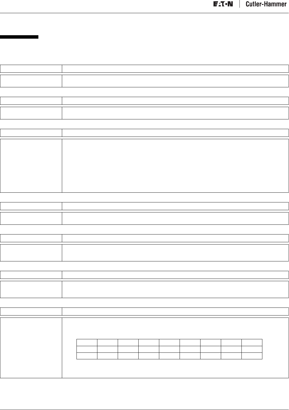
Intelligent Technologies (IT.) D77A I/O Module Products
48 For more information visit: www.EatonElectrical.com MN05002001E
Appendix A
Data Parameters
Table 33: 0x0001 (1) Production Data
Table 34: 0x0002 (2) Consumption Data
Table 35: 0x0003 (3) QCPort Status
Table 36: 0x0004 (4) Application Status (Available in I/O As Control Elements)
Table 37: 0x0005 (5) Discrete Data Input (Available in I/O As Control Elements)
Table 38: 0x0006 (6) Discrete Data Output (Available in I/O As Control Elements)
Table 39: 0x006B (107) Analog Input Status (Available in I/O As Control Elements)
* Setting the bit from “0” to “1” indicates that the condition is true.
Size Description
Varies This list contains the concatenated values of QCPort Parameters specified in QCPort Configuration Parameter
0x800C, Production List.
Size Description
Varies This list contains the concatenated values of QCPort Parameters specified in QCPort Configuration Parameter
0x800D, Consumption List.
Size Description
1 Byte This parameter indicates the QCPort fault condition that caused a device to enter the Fault Mode, as indicated
below:
0x00 — No QCPort Fault
0x01 — Node ID Conflict
0x02 — Invalid Node ID in Master/Slave
0x03 — Physical Node ID does not match actual ID
0x04 — Duplicate configured nodes online
0x05 — Dynamic Node ID overflow
0x06 — Invalid baud rate selected
0x07 — Errant Device fault
0x08 — Problem with data in non-volatile memory
Size Description
2 Bytes This parameter indicates the application status of the QCPort device. It reports the most recent fault or warning.
If there have been no faults or warnings, it reports 0. Reset clears this parameter.
Size Description
n Bytes A series of BYTES that represent discrete digital inputs on a device. This parameter is used in any input module
having discrete inputs.
The least significant bit of byte 0 corresponds to input point 0.
Size Description
n Bytes A series of BYTES representing the state of the outputs of a discrete output device. This parameter is used in
any module having discrete outputs. The least significant bit of byte 0 corresponds to output point 0.
Parameter 0x8023, “Output Comm Loss Behavior” is used in conjunction with this parameter.
Size Description
n Bytes This provides channel status for the analog inputs.
U = Under Range
O = Over Range
Byte Bit 7 Bit 6 Bit 5 * Bit 4 * Bit 3 Bit 2 Bit 1 * Bit 0 *
0 O1U1 O0U0
1 O3U3 O2U2
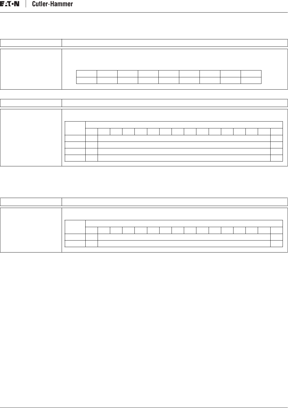
Intelligent Technologies (IT.) D77A I/O Module Products
MN05002001E For more information visit: www.EatonElectrical.com 49
Table 40: 0x006C (108) Analog Output Status (Available in I/O As Control Elements)
Table 41: 0x006F (111) 16 bit Signed Analog Input Data (Available in I/O As Control Elements)
Sign Bit*
1 = True (-)
0 = False (+)
Table 42: 0x0070 (112) 16 bit Signed Analog Output Data (Available in I/O As Control Elements)
Sign Bit*
1 = True (-)
0 = False (+)
Size Description
n Bytes This provides channel status for the analog outputs.
U = Under Range
O = Over Range
Size Description
Word This provides the 16 bit signed analog input data for the module.
Size Description
Word This provides the 16 bit signed analog output data for the module.
Byte Bit 7 Bit 6 Bit 5 * Bit 4 * Bit 3 Bit 2 Bit 1 * Bit 0 *
0 O1U1 O0U0
Word
Bit Position
1514131211109876543210
0 SB* Analog Input Data Channel 0 0
1 SB* Analog Input Data Channel 1 0
2 SB* Analog Input Data Channel 2 0
3 SB* Analog Input Data Channel 3 0
Word
Bit Position
1514131211109876543210
0 SB* Analog Input Data Channel 0 0
1 SB* Analog Input Data Channel 1 0
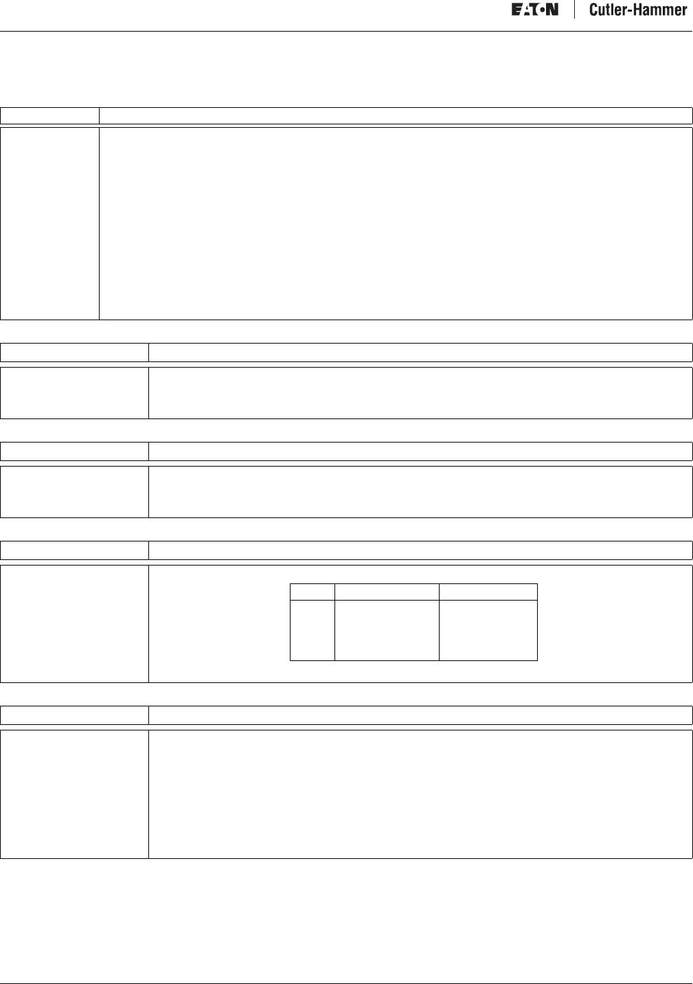
Intelligent Technologies (IT.) D77A I/O Module Products
50 For more information visit: www.EatonElectrical.com MN05002001E
Configuration Parameters
None of the Configuration Parameters support I/O data.
Table 43: 0x8001 (32769) Device Identity
Table 44: 0x8002 (32770) Configuration CRC
Table 45: 0x8003 (32771) Node ID
Table 46: 0x8004 (32772) Operating Mode
Table 47: 0x8005 (32773) QCPort Baud Rate
Size Description
14 bytes This read-only parameter contains information that uniquely identifies a device, including the following elements:
Product Code
(2 bytes) A device’s unique product code must be reported. Each
vendor must maintain its own list of product codes.
Vendor ID
(2 bytes) Each QCPort vendor must use their unique ID as assigned
by Eaton Electrical.
Serial Number
(4 bytes) A device’s serial number must be reported. This value must
be unique for a particular manufacturer across all device
types.
Hardware Revision
(2 bytes) Major revision must be reported in the MSB. Minor revision
must be reported in the LSB.
Firmware Revision
(2 bytes) Major revision must be reported in the MSB. Minor revision
must be reported in the LSB.
QCPort Revision
(2 bytes) Major revision must be reported in the MSB. Minor revision
must be reported in the LSB.
Size Description
2 bytes Used for confirmation of a device’s configuration. Normally, the initial values of selected configuration
parameters would be included in the calculation. The product instruction leaflet should describe which
parameters are actually included. To facilitate node replacement, Device Identity information should not be
included in this calculation.
Size Description
2 bytes This parameter specifies a device’s Node ID. The Group ID is the Most Significant Byte and the Member ID is the
Least Significant Byte.
An Initial Value of 0x0000 indicates an unconfigured state. In this state, a device assumes a current value based
on the level of switch support implemented in hardware.
Size Description
1 byte This parameter specifies a device’s operating mode, as follows:
Size Description
1 byte This parameter specifies the QCPort baud rate for a device as indicated below:
0x00 — 9,600
0x01 — 19,200
0x02 — 38,400
0x03 — 57,600
0x04 — 115,200
0x05 — 230,400
0x06 — 460,800
Note that the current value of the baud rate cannot be directly modified. The current value is set to the initial
value upon reset. Therefore, writing to the initial value and resetting the device sets a new current value.
Mode Description Active/Passive
0x00
0x01
0x02
0x03
0x04
Unconfigured
Simple System
Master/Slave
Wire Replacer
Faulted
Passive
Passive
Active
Passive
Passive
Intelligent Technologies (IT.) D77A I/O Module Products
MN05002001E For more information visit: www.EatonElectrical.com 51
Table 48: 0x8006 (32774) Slave Address
Table 49: 0x8007 (32775) Production Destination
Table 50: 0x8008 (32776) Device ID Tag
Table 51: 0x8009 (32777) Production Interval
Table 52: 0x800A (32778) Consumption Interval
Table 53: 0x800B (32779) Parameter List
Table 54: 0x800C (32780) Production List
Table 55: 0x800D (32781) Consumption List
Table 56: 0x800E (32782) Languages Supported
Size Description
1 byte This parameter specifies the address used by a Master for data transfers in the Master/Slave Data Protocol.
The default value must be 0x00 (unconfigured), requiring a Master to set this value prior to using the Master/
Slave Data Protocol.
Size Description
2 bytes This parameter specifies the destination Node ID to be used by a device in either the Simple System or Wire
Replacer Data Protocols. The MSB indicates the Group ID; the LSB indicates the Member ID.
An Initial Value of 0x0000 indicates an unconfigured state. In this state, a device assumes a current value equal
to its Group ID and a Member ID of 0x00. This results in its Production Data being targeted at all members of its
Group.
Size Description
32 bytes This parameter specifies the 32-character ASCII string ID tag assigned to a device, pre-assigned at the factory
but can be set by the user.
Size Description
2 bytes This parameter specifies the rate, in milliseconds, at which a producing device generates a Data Protocol
message in either Simple System or Wire Replacer mode.
A value of 0 disables this timer.
Size Description
2 bytes This parameter is the value to which the consumption timer is set whenever there is a set of the current value of
any parameter on the consumption list.
Expiration of this interval causes the module to execute communications loss behavior.
A value of 0 disables this timer.
Size Description
92 bytes This read-only list specifies the n QCPort Parameters that a device supports.
Size Description
2 bytes This 2n-byte read-only list specifies the n QCPort Parameters included in a device’s QCPort Data Parameter
0x0001, Production Data.
Setting Parameter Attribute 0x09, “Production List Member,” to TRUE, designates a Parameter’s membership in
this list. Only Parameters supporting Attribute 0x09 are eligible for inclusion in this list.
Ordering of Parameter IDs in the Production List is based first on Parameter data size and then sequentially
within Parameters of like size. For example, all Parameters with an even number of bytes would appear first
sequentially, followed by Parameters with an odd number of bytes.
Size Description
2 bytes This 2n-byte read-only list specifies the n QCPort Parameters included in a device’s QCPort Data Parameter
0x0002, Consumption Data.
Setting Parameter Attribute 0x0A, “Consumption List Member,” to TRUE, designates a Parameter’s membership
in this list. Only Parameters supporting Attribute 0x0A are eligible for inclusion in this list.
Ordering of Parameter IDs in the Consumption List is based first on Parameter data size and then sequentially
within Parameters of like size. For example, Parameters with an even number of bytes would appear first
sequentially, followed by Parameters with an odd number of bytes.
Size Description
n bytes This is a list of languages supported in the product. It consists of a list of bytes, each representing a different
language.
0x00 — English
0x01 — Spanish
0x02 — French
0x03 — German
0x04 — Italian

Intelligent Technologies (IT.) D77A I/O Module Products
52 For more information visit: www.EatonElectrical.com MN05002001E
Table 57: 0x800F (32783) Language Selection
Table 58: 0x8010 (32784) Device Semaphore
Table 59: 0x8023 (32803) Output Comm Loss Action
Table 60: 0x8024 (32804) Input Debounce
Table 61: 0x804D (32845) Physical Node ID Setting
Table 62: 0x80CF (32975) Analog Output Communication Loss Behavior
Table 63: 0x80D0 (32976) Analog Output Communication Loss Value
Table 64: 0x80D1 (32977) Input Range Setting
Table 65: 0x80D2 (32978) Analog Output Range
Size Description
1 byte Holds the currently selected language from the list in parameter 800E.
Size Description
4 bytes The purpose of this parameter is to provide a method for tools to access a QCPort node in a non-conflicting
manner.
This parameter consists of a field of 2 UNITs organized as follows:
Byte
Node ID Low byte
Node ID High byte
Lockout Time in tenths of seconds Low byte
Lockout Time in tenths of seconds High byte
If the above 4 bytes are 0, anyone can write to this parameter. This parameter is cleared by the Clear Semaphore
command that can be sent by anyone. If all 4 bytes are not 0 and a write (other than a clear) to this parameter is
attempted, an error message will be returned. The parameter will be cleared when the timer counts down to 0.
If the node ID field is 0, all set parameters to the node will be accepted. If the node ID field is not 0, set parameter
commands to the node will only be accepted from the device having the same node ID as that contained in this
parameter. Note that if the node ID is set to zero at the same time that a non-zero value is loaded to the timer, the
timer will not decrement.
Size Description
The n bytes Used in discrete output modules. Each bit of this parameter is associated with an output bit and defines the
behavior of that output upon detection of communications loss.
If a bit in this parameter is 1, the output bit holds the last state.
If a bit is 0, the output bit is determined by the initial value.
Size Description
The n bytes Used with discrete input devices. This parameter consists of a series of UNITs, two bytes for each discrete input
and holds the debounce time for that input.
Size Description
2 bytes This parameter may be used with modules having a hardware node ID switch and represents the actual setting
of that switch.
Size Description
n Bytes Determines the communication loss behavior of the output module.
0 = Hold last state
1 = Use Communication Loss Value
2 = Use Initial Value
Size Description
Word Value that the output channel will go to if selected using the communication loss behavior.
1-32767
Size Description
1 Word Determines analog input data range:
0 = 0 - 10V
1 = 0 - 5V
2 = 1 - 5v
3 = 0 - 20mA
4 = 4 - 20mA
Size Description
1 Word Determines analog output data range.
0 = 0 - 10V
1 = 0 - 5V
2 = 1 - 5v
3 = 0 - 20mA
4 = 4 - 20mA
Intelligent Technologies (IT.) D77A I/O Module Products
MN05002001E For more information visit: www.EatonElectrical.com 53
Analog Data Registers
Table 66: Register 1; Serial Number
Table 67: Register 2; Hardware Revision
Table 68: Register 3; Analog Filter Setting
IT. Publications and Support
Publications
Ta b l e 6 9 : IT. Publications
For copies of these and other publications please visit our website at www.EatonElectrical.com.
Size Description
4 bytes, read only Serial number of module
Size Description
2 bytes, read only Hardware version of module
Size Description
2 bytes, read only Filter setting of analog input channel
0 = 50 Hz
1 = 60 Hz
2 = 250 Hz
3 = 500 Hz
Publication Description
MN05002001E IT. D77A I/O Module Products Installation and Users Manual
MN05001002E IT. QCPort System Install and Planning Guide
MN05004002E IT. DeviceNet Adapter Installation and User Manual

© 2005 Eaton Corporation
All Rights Reserved
Publication No. MN05002001E
Revision 4/ November 2006
Eaton Electrical Inc.
1000 Cherrington Parkway
Moon Township, PA 15108-4312
USA
tel: 1-800-525-2000
www.EatonElectrical.com
Company Information
Eaton’s electrical business is a global leader in electrical control, power distribution, and industrial automation products and services.
Through advanced product development, world-class manufacturing methods, and global engineering services and support, Eaton’s
electrical business provides customer-driven solutions under brand names such as Cutler-Hammer®, Powerware®, Durant®,
Heinemann®, Holec®
and MEM®, which globally serve the changing needs of the industrial, utility,
light commercial, residential, and OEM
markets. For more information, visit www.EatonElectrical.com.
Eaton Corporation is a diversified industrial manufacturer with 2004 sales of $9.8 billion. Eaton is a global leader in electrical systems and
components for power quality, distribution and control; fluid power systems and services for industrial, mobile and aircraft equipment;
intelligent truck drivetrain systems for safety and fuel economy; and automotive engine air management systems, powertrain solutions
and specialty controls for performance, fuel economy and safety. Eaton has 56,000 employees and sells products to customers in more
than 125 countries. For more information, visit www.eaton.com.
