Eaton Electrical Etn1000 Users Manual Sunville Grid PV Inverter Installation And Operation
ETN2000 to the manual d969c7e8-b473-4fc4-aba8-ac7ff1d53667
2015-02-06
: Eaton-Electrical Eaton-Electrical-Etn1000-Users-Manual-537198 eaton-electrical-etn1000-users-manual-537198 eaton-electrical pdf
Open the PDF directly: View PDF ![]() .
.
Page Count: 33
EATON ETN1000 / ETN2000
Grid PV-Inverter
Installation and Operation Manual
Version 1.6 E 2010.06

1
Before you start…....................................................................................................3
Safety instructions...................................................................................................4
Limited Warranty.....................................................................................................6
1. Overview.........................................................................................................7
2. Features..........................................................................................................8
3. Installation instructions.................................................................................9
Opening the package ...............................................................................9
Before installation.....................................................................................9
Mounting Inverter to the wall .................................................................. 11
Connecting to the grid (AC utility)...........................................................14
Connect to PV Panel (DC input).............................................................15
Checking.................................................................................................16
4. System Diagram...........................................................................................17
5. Operating Your PV-Inverter.........................................................................18
Modes of operation.................................................................................18
Front Panel arrangement .......................................................................19
LED.........................................................................................................19
Function Key...........................................................................................19
Accuracy of the reading..........................................................................19

Edition 1.6E, 2010/06 2
Front Panel.............................................................................................20
LCD Display Sequence: .........................................................................22
Maximum Power Point Tracking (MPPT) ...............................................22
Maximum Power Point Tracking (MPPT) ...............................................23
6. Inverter Status..................................................................................................24
Display information.................................................................................24
7. Communications..............................................................................................27
8. Trouble shooting..............................................................................................29
9. Specifications...................................................................................................31
Electrical .................................................................................................31

3
Before you start…
Congratulations on choosing EATON ETN1000 / ETN2000 Grid PV-Inverter,
a product from EATON Grid PV-Inverter is a highly reliable product due to its
innovative design and perfect quality control. Such an inverter is used in
high demand, grid-linked PV systems.
T
Th
hi
is
s
m
ma
an
nu
ua
al
l
c
co
on
nt
ta
ai
in
ns
s
i
im
mp
po
or
rt
ta
an
nt
t
i
in
nf
fo
or
rm
ma
at
ti
io
on
n
r
re
eg
ga
ar
rd
di
in
ng
g
i
in
ns
st
ta
al
ll
la
at
ti
io
on
n
a
an
nd
d
s
sa
af
fe
e
o
op
pe
er
ra
at
ti
io
on
n
o
of
f
t
th
hi
is
s
u
un
ni
it
t.
.
B
Be
e
s
su
ur
re
e
t
to
o
r
re
ea
ad
d
t
th
hi
is
s
m
ma
an
nu
ua
al
l
c
ca
ar
re
ef
fu
ul
ll
ly
y
b
be
ef
fo
or
re
e
u
us
si
in
ng
g.
.
If you encounter any problems during installation or operation of this unit, first
check this manual before contacting your local dealer or representative.
Instructions inside this manual will help you solve most installation and
operation difficulties.
Thank you again for choosing our product. Please keep this manual handy
for quick reference.

Edition 1.6E, 2010/06 4
Safety instructions
z Risk of Electric Shock
1. Do not remove the casing. Inverter contains no user serviceable parts.
Refer servicing to qualified service personnel.
B
Bo
ot
th
h
A
AC
C
a
an
nd
d
D
DC
C
v
vo
ol
lt
ta
ag
ge
e
s
so
ou
ur
rc
ce
es
s
a
ar
re
e
t
te
er
rm
mi
in
na
at
te
ed
d
i
in
ns
si
id
de
e
t
th
he
e
P
PV
V-
-I
In
nv
ve
er
rt
te
er
r.
.
P
Pl
le
ea
as
se
e
d
di
is
sc
co
on
nn
ne
ec
ct
t
t
th
he
es
se
e
c
ci
ir
rc
cu
ui
it
ts
s
b
be
ef
fo
or
re
e
s
se
er
rv
vi
ic
ci
in
ng
g.
.
2. When a photovoltaic panel is exposed to light, it generates a DC voltage.
When connected to this equipment, a photovoltaic panel will charge
the DC link capacitors.
3. Energy stored in this equipment’s DC link capacitors presents a risk of
electric shock. Even after the unit is disconnected from the grid and
photovoltaic panels, high voltages may still exist inside the PV-Inverter.
Do not remove the casing until at least 30 minutes after disconnecting
all power sources.
4. This unit is designed to feed power to the public power grid (utility) only.
Do not connect this unit to an AC source or generator. Connecting
Inverter to external devices could result in serious damage to your
equipment.
5. Carefully remove the unit from its packaging and inspect for external
damage. If you find any imperfections, please contact your local
dealer.

5
z Hot surfaces
Although designed to meet all safety requirements, some
parts and surfaces of Inverter are still hot during operation.
To reduce the risk of injury, do not touch the heat sink at the back of the
PV-Inverter or nearby surfaces while Inverter is operating.

Edition 1.6E, 2010/06 6
Limited Warranty
Inverter comes with a limited warranty. This warranty includes all defects of
design, components and manufacturing. Excluded from warranty are
damages due to:
z Breaking the product seal (opening the casing)
z Improper transportation and delivery
z Unqualified persons opening the unit
z Improper installation
z Unauthorized modification, testing or repairing
z Use and application beyond the definition in this manual
z Application beyond the scope of safety standards
z Acts of nature such as lighting, fire, storm etc.
The right to repair and/or replace the unit is at the manufacturers’ discretion.
Any damages discovered during installation should be submitted via a
written damage report within 5 working days of receiving the PV-Inverter.
Otherwise EATON is not responsible for damages beyond the scope of this
warranty.
7
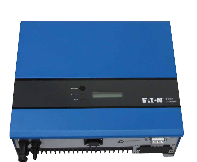
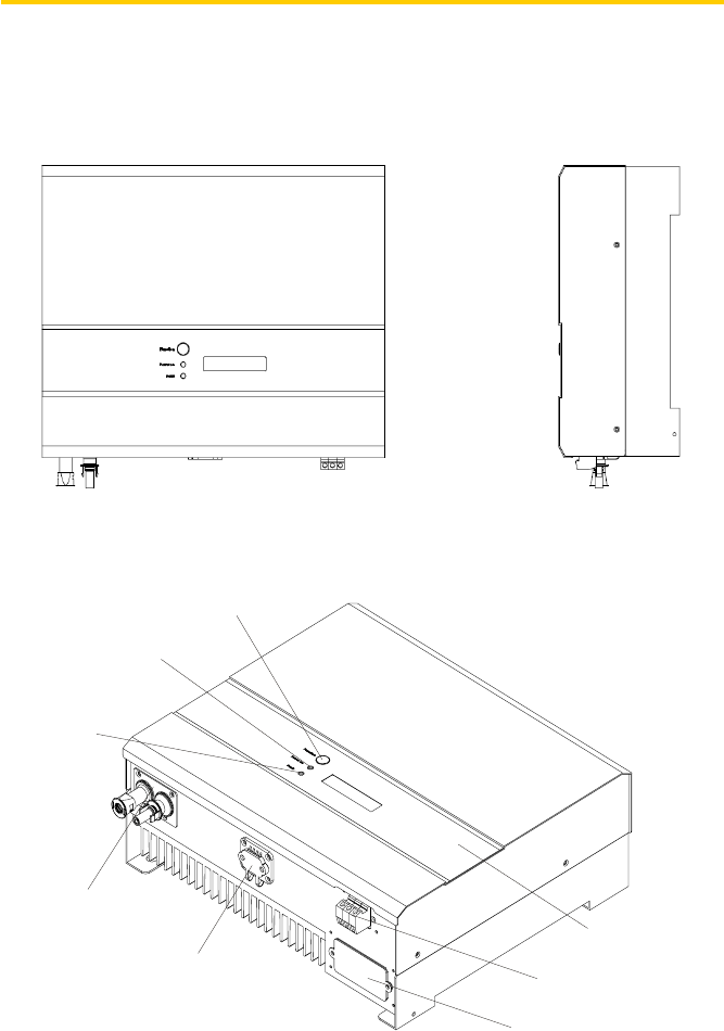
1. Overview
1.0 kW / 2.0kW Design Overview
Front View Bottom View
Parts Description
Display in
f
ormation switch
Operation LED,
Green , normal
Operation LED,
Red, fault status
Solar panel input
RS232 cover
Optional communications
slot: RS232 & others
Utility (AC) connection:
Terminal Black
LCD Display: Showing
the inverter status

Edition 1.6E, 2010/06 8
2. Features
z Very high conversion efficiency (up to 96%)
z MPPT (Maximum Power Point Tracking)
z Higher power capacity than similar products of the same size.
z Embedded LCD display showing complete status information
z Natural convection cooling. Quiet, fan-less design
z Stylish, modern casing
z Compact, small profile
z High reliability, and Easy to install
z Maintenance free
z Standard RS-232, optional RS-485 and others
z No external GFCI breaker is required

9
3. Installation instructions
Opening the package
After opening the package, please check the contents of the box. It
should contain the following:
1. One Inverter
2. One Instruction manual
3. One mounting frame
4. 4 mounting screws
5. 2 safety-lock screws
6. One cable gland and TB cover for AC cable
Before installation
Before starting installation please consider the following items:
T
Th
hi
is
s
u
un
ni
it
t
i
is
s
d
de
es
si
ig
gn
ne
ed
d
f
fo
or
r
i
in
nd
do
oo
or
r
u
us
sa
ag
ge
e.
.
D
Do
o
n
no
ot
t
e
ex
xp
po
os
se
e
t
th
he
e
u
un
ni
it
t
t
to
o
w
we
et
t,
,
o
or
r
m
mo
oi
is
st
t
c
co
on
nd
di
it
ti
io
on
ns
s.
.
D
Do
o
n
no
ot
t
e
ex
xp
po
os
se
e
t
th
he
e
P
PV
V-
-I
In
nv
ve
er
rt
te
er
r
t
to
o
d
di
ir
re
ec
ct
t
s
su
un
nl
li
ig
gh
ht
t.
.
D
Di
ir
re
ec
ct
t
s
su
un
nl
li
ig
gh
ht
t
i
in
nc
cr
re
ea
as
se
es
s
t
th
he
e
i
in
nt
te
er
rn
na
al
l
t
te
em
mp
pe
er
ra
at
tu
ur
re
e
t
th
ha
at
t
m
ma
ay
y
r
re
ed
du
uc
ce
e
c
co
on
nv
ve
er
rs
si
io
on
n
e
ef
ff
fi
ic
ci
ie
en
nc
cy
y.
.
9 Check the ambient temperature of installation is within specified
range -20 ~ +55°C.
9 The AC grid voltage is between 206 and 264VAC, 50/60Hz.
9 Electric utility company has approved the grid connection.
9 Qualified personnel are performing the installation.
9 Adequate convection space surrounds the inverter.
9 Inverter is being installed away from explosive vapors.
9 No flammable items are near the inverter.

Edition 1.6E, 2010/06 10
I
In
nv
ve
er
rt
te
er
r
c
ca
an
n
b
be
e
i
in
ns
st
ta
al
ll
le
ed
d
a
an
nd
d
o
op
pe
er
ra
at
te
ed
d
a
at
t
l
lo
oc
ca
at
ti
io
on
ns
s
w
wh
he
er
re
e
t
th
he
e
a
am
mb
bi
ie
en
nt
t
t
te
em
mp
pe
er
ra
at
tu
ur
re
e
i
is
s
u
up
p
t
to
o
5
55
5°
°C
C.
.
H
Ho
ow
we
ev
ve
er
r,
,
f
fo
or
r
o
op
pt
ti
im
ma
al
l
o
op
pe
er
ra
at
ti
io
on
n,
,
i
it
t
i
is
s
r
re
ec
co
om
mm
me
en
nd
de
ed
d
t
th
ha
at
t
I
In
nv
ve
er
rt
te
er
r
i
is
s
i
in
ns
st
ta
al
ll
le
ed
d
w
wh
he
er
re
e
t
th
he
e
a
am
mb
bi
ie
en
nt
t
t
te
em
mp
pe
er
ra
at
tu
ur
re
e
i
is
s
b
be
et
tw
we
ee
en
n
0
0~
~4
40
0°
°C
C.
.
11
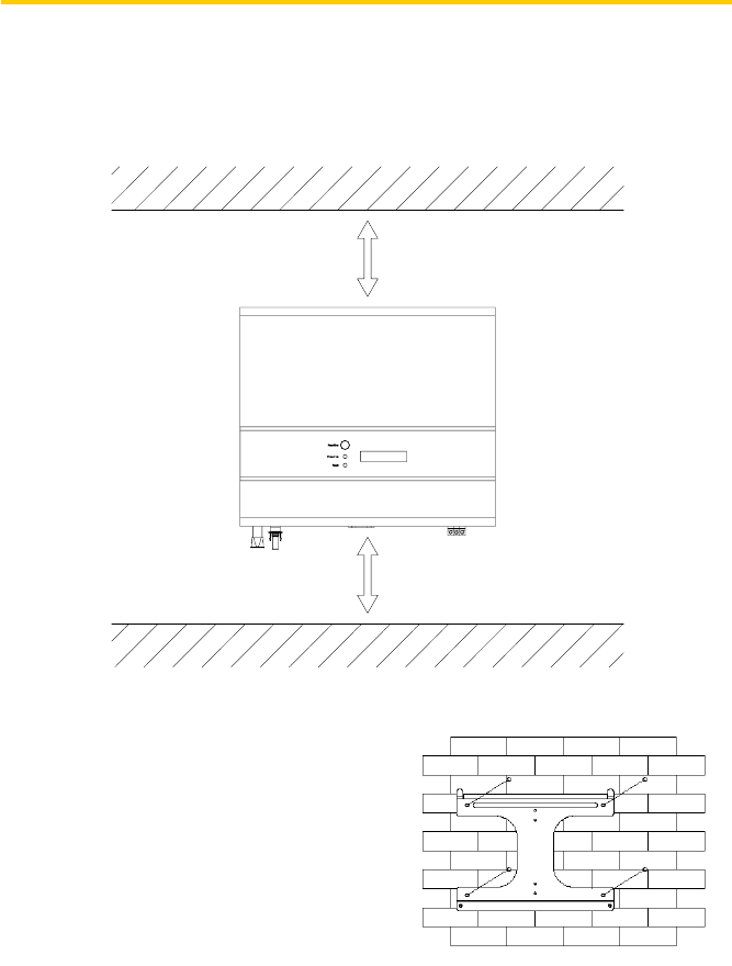
Mounting Inverter to the wall
1. Select a wall or solid vertical surface that can support the PV-Inverter.
2. Inverter requires adequate cooling space. Allow at least 20cm space
above and below the inverter.
3. Using the mounting frame as a template, drill 4 holes as illustrated in the
following figures.
4. Fix the mounting frame as the
figure shows.
Edition 1.6E, 2010/06 12
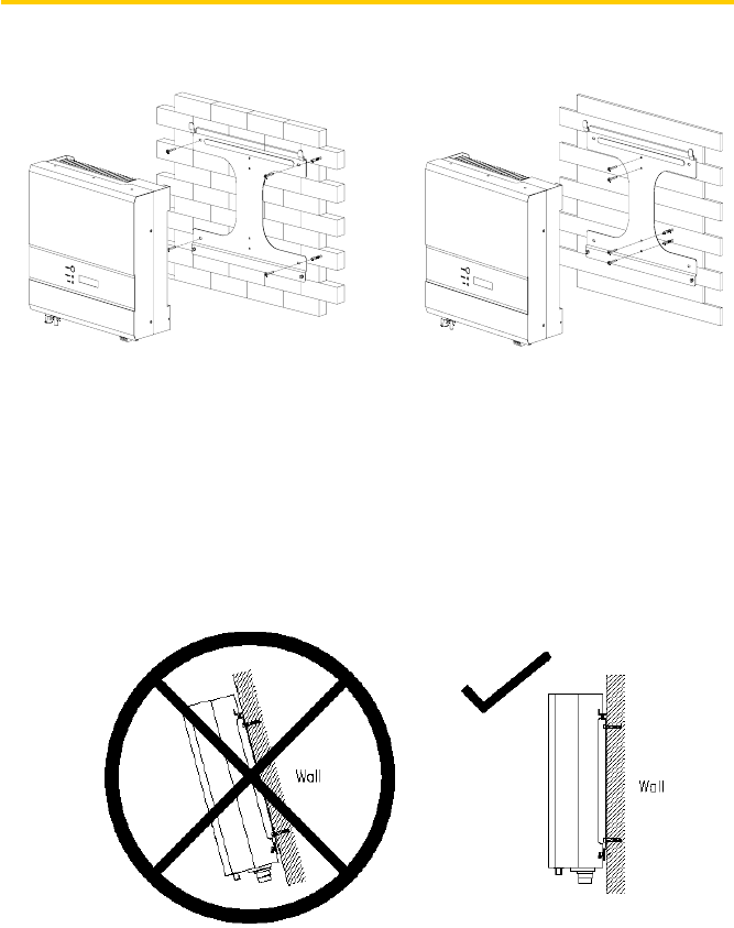
5. Hang the inverter on the mounting frame
S
Se
el
le
ec
ct
tt
th
he
ei
in
ns
st
ta
al
ll
la
at
ti
io
on
nl
lo
oc
ca
at
ti
io
on
ns
so
ot
th
ha
at
tt
th
he
es
st
ta
at
tu
us
sd
di
is
sp
pl
la
ay
yc
ca
an
nb
be
ee
ea
as
si
il
ly
yv
vi
ie
ew
we
ed
d.
.
C
Ch
ho
oo
os
se
ea
as
st
tr
ro
on
ng
gm
mo
ou
un
nt
ti
in
ng
gw
wa
al
ll
lt
to
op
pr
re
ev
ve
en
nt
tv
vi
ib
br
ra
at
ti
io
on
ns
sw
wh
hi
il
le
ei
in
nv
ve
er
rt
te
er
ri
is
s
o
op
pe
er
ra
at
ti
in
ng
g.
.
6. Check the installation conditions
a) Do not install the PV-Inverter on a slanted surface
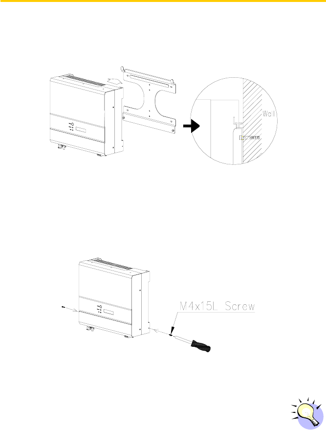
13
b) Check the upper straps of PV-Inverter and ensure it fits on to the
bracket
c) Insert safety-lock screws to the bottom leg to secure the inverter
C
Ch
he
ec
ck
kt
th
he
es
se
ec
cu
ur
re
em
mo
ou
un
nt
ti
in
ng
go
of
ft
th
he
eP
PV
V-
-I
In
nv
ve
er
rt
te
er
rb
by
yt
tr
ry
yi
in
ng
gt
to
or
ra
ai
is
se
ei
it
t
f
fr
ro
om
mt
th
he
eb
bo
ot
tt
to
om
m.
.T
Th
he
eP
PV
V-
-I
In
nv
ve
er
rt
te
er
rs
sh
ho
ou
ul
ld
dr
re
em
ma
ai
in
nf
fi
ir
rm
ml
ly
ya
at
tt
ta
ac
ch
he
ed
d.
.
Edition 1.6E, 2010/06 14
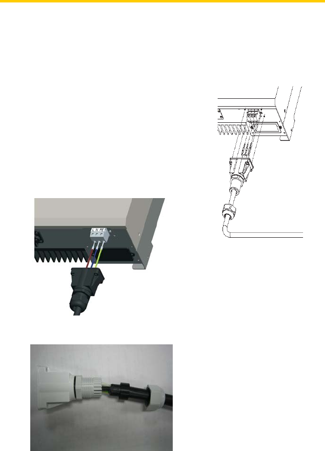
Connecting to the grid (AC utility)
1. Measure grid (utility) voltage and frequency. It should be 230VAC (or
220VAC), 50/60Hz, and single phase.
2. Open the breaker or fuse between PV-Inverter and utility.
3. For Inverter, connect AC wires as
follows:
z Insert utility wires through cable gland.
Connect wires according to polarities
indicated on terminal block. L → LINE
(brown), N → Neutral (blue) and →
system ground (green).
z Fasten the gland plate in order to make sure cable is firmly fixed.
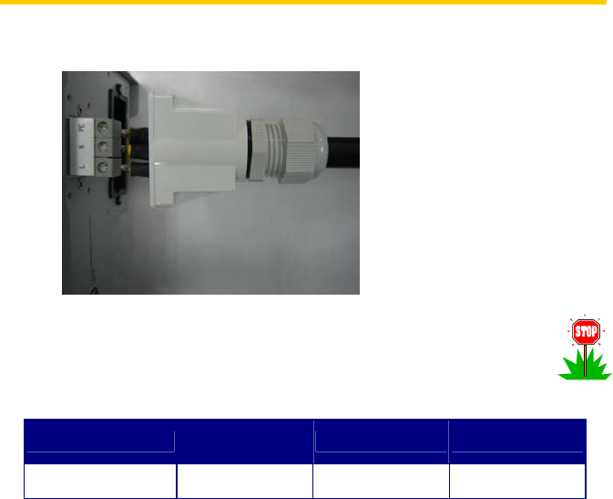
15
z Twist the gland, attached screws in order to seal the AC gland cover.
T
To
o
p
pr
re
ev
ve
en
nt
t
r
ri
is
sk
k
o
of
f
e
el
le
ec
ct
tr
ri
ic
c
s
sh
ho
oc
ck
k,
,
e
en
ns
su
ur
re
e
t
th
he
e
g
gr
ro
ou
un
nd
d
w
wi
ir
re
e
i
is
s
p
pr
ro
op
pe
er
rl
ly
y
e
ea
ar
rt
th
he
ed
d
b
be
ef
fo
or
re
e
o
op
pe
er
ra
at
ti
in
ng
g
t
th
he
e
P
PV
V-
-I
In
nv
ve
er
rt
te
er
r.
.
4. Suggested cable width for AC wire.
Model Diameter φ
(mm) Area (mm2) AWG no.
EATON ETN1000
EATON ETN2000 ≥1.02 ≥1.25 ≤16
Connect to PV Panel (DC input)
1. Make sure the maximum open circuit voltage (Voc) of each PV string is
less than 500VDC UNDER ANY CONDITION. We recommend Voc less
than 360VDC with ambient temperature of 25°C.
2. Use MC (Multi-contact®) connectors for PV array terminals.
3. Connect the positive and negative terminals from the PV panel to
positive (+) terminals and negative (-) terminals on the PV-Inverter.
Each DC terminal on Inverter can withstand up to 5ADC in 1.0kW and

Edition 1.6E, 2010/06 16
10ADC in 2.0kW.
B
Be
ef
fo
or
re
e
c
co
on
nn
ne
ec
ct
ti
in
ng
g
P
PV
V
p
pa
an
ne
el
ls
s
t
to
o
D
DC
C
t
te
er
rm
mi
in
na
al
ls
s,
,
p
pl
le
ea
as
se
e
m
ma
ak
ke
e
s
su
ur
re
e
t
th
he
e
p
po
ol
la
ar
ri
it
ty
y
i
is
s
c
co
or
rr
re
ec
ct
t.
.
I
In
nc
co
or
rr
re
ec
ct
t
p
po
ol
la
ar
ri
it
ty
y
c
co
on
nn
ne
ec
ct
ti
io
on
n
c
co
ou
ul
ld
d
p
pe
er
rm
ma
an
ne
en
nt
tl
ly
y
d
da
am
ma
ag
ge
e
t
th
he
e
u
un
ni
it
t.
.
P
Pl
le
ea
as
se
e
c
ch
he
ec
ck
k
t
th
he
e
s
sh
ho
or
rt
t-
-c
ci
ir
rc
cu
ui
it
t
c
cu
ur
rr
re
en
nt
t
o
of
f
t
th
he
e
P
PV
V
s
st
tr
ri
in
ng
g.
.
T
Th
he
e
t
to
ot
ta
al
l
s
sh
ho
or
rt
t-
-c
ci
ir
rc
cu
ui
it
t
c
cu
ur
rr
re
en
nt
t
o
of
f
t
th
he
e
P
PV
V
s
st
tr
ri
in
ng
g
s
sh
ho
ou
ul
ld
d
b
be
e
l
le
es
ss
s
t
th
ha
an
n
t
th
he
e
i
in
nv
ve
er
rt
te
er
r’
’s
s
m
ma
ax
xi
im
mu
um
m
D
DC
C
c
cu
ur
rr
re
en
nt
t.
.
H
Hi
ig
gh
h
v
vo
ol
lt
ta
ag
ge
es
s
e
ex
xi
is
st
t
w
wh
he
en
n
t
th
he
e
P
PV
V
p
pa
an
ne
el
l
i
is
s
e
ex
xp
po
os
se
ed
d
t
to
o
t
th
he
e
s
su
un
n.
.
T
To
o
r
re
ed
du
uc
ce
e
r
ri
is
sk
k
o
of
f
e
el
le
ec
ct
tr
ri
ic
c
s
sh
ho
oc
ck
k,
,
a
av
vo
oi
id
d
t
to
ou
uc
ch
hi
in
ng
g
l
li
iv
ve
e
c
co
om
mp
po
on
ne
en
nt
ts
s
a
an
nd
d
t
tr
re
ea
at
t
c
co
on
nn
ne
ec
ct
ti
io
on
n
t
te
er
rm
mi
in
na
al
ls
s
c
ca
ar
re
ef
fu
ul
ll
ly
y.
.
Checking
1. When the PV panels are connected and their output voltage is greater
than 100 VDC but the AC grid is not yet connected, the message on the
LCD display produce the following messages in order: “MODEL” ->
“Waiting” -> “No Utility”. The display repeats “No Utility” and the RED
“fault LED” turns on.
2. Close the AC breaker or fuse between PV-Inverter and grid. The
normal operating sequence begins.
3. Under normal operating conditions the LCD displays “Pac=xxxx.xW”.
That is the power fed to the grid. The green LED turns lights-up.
4. This completes the check.
17
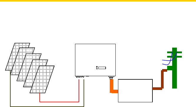
4. System Diagram
The typical connection diagram for the entire PV system is shown in the
following figure.
1. PV Panel: Provide DC power to inverter.
2. EATON ETN1000 / ETN2000 PV Inverter converts DC (Direct Current)
power from PV panel(s) to AC (Alternating Current) power. Because
Inverter is grid-connected it controls the current amplitude according to
the PV Panel power supply. Inverter always tries to convert the
maximum power from your PV panel(s).
3. Connection system: This “interface” between Utility and PV-Inverter
may consist of electrical breaker, fuse and connecting terminals. To
comply with local safety standards and codes, the connection system
should be designed and implemented by a qualified technician.
4. Utility: Referred to as “grid” in this manual, is the way your electric
power company provides power to your place. Please note that
Inverter can only connect to low-voltage systems (namely, 220,
230VAC, 50/60Hz).
+-Connection
system
Utility
PV panel

Edition 1.6E, 2010/06 18
5. Operating Your PV-Inverter
Modes of operation
There are 3 different modes of operation.
1. Normal mode: In this mode, Inverter works normally. Whenever the
supplied power from PV panel is sufficient (voltage>150VDC), Inverter
converts power to the grid as generated by the PV panel. If the power is
insufficient, (voltage<100VDC) Inverter enters a “waiting” state. Whilst
“waiting” Inverter uses just enough power from the PV panel monitor
internal system status. In normal mode the green LED is on.
2. Fault mode: The internal intelligent controller can continuously monitor
and adjust the system status. If Inverter finds any unexpected
conditions such as grid problems or internal failure, it will display the
information on its LCD and light up the red “Fault” LED.
3. Shutdown mode: During periods of little or no sunlight, Inverter
automatically stops running. In this mode, Inverter does not take any
power from the grid. The display and LED’s on the front panel do not
work.
19
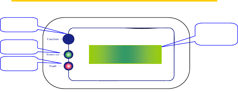
Front Panel arrangement
LED
There are 2 LED’s on Inverter, one is green and the other is red.
Normally, only the green LED switches on during operation. Their
indicated status is explained as follows:
1. Power on (green LED): It lights to indicate that Inverter is running.
2. Fault (red LED): Illuminates during a “fault” or “failure”. Details of
possible faults and their solutions can be found in Chapter
6,”Inverter Status”.
Function Key
Function Key is a key on PV-Inverter which can be pressed so as to
rotate between each menu.
Accuracy of the reading
Normally, the accuracy of LCD reading is around ±2%. In all ranges of
operation, the accuracy is up to ±5%.
Function Key LCD (Liquid
Crystal Display)
Power-on LED
Fault LED P
P
Pa
a
ac
c
c=
=
=x
x
xx
x
xx
x
xx
x
x.
.
.x
x
xW
W
W
Front Panel
Operating Inverter is quite easy. During normal operation, Inverter runs
automatically. However, to achieve maximum conversion efficiency of
Inverter, please read through the following information:
1. Automatic ON-OFF: Inverter starts up automatically when DC-power
from the PV panel is sufficient. Once the PV-Inverter starts it enters
one of the following 3 states:
z Standby: The PV string can only provide just enough voltage to
minimum requirements of the controller.
z Waiting: When the PV string DC voltage is greater than 100V,
Inverter enters a “waiting” state and attempts to connect to the
grid.
z Normal operation: When PV string DC voltage is greater than
150V, Inverter operates in the normal state.
In this state, it feeds power to the grid.
Inverter automatically stops when the PV power is
not enough.
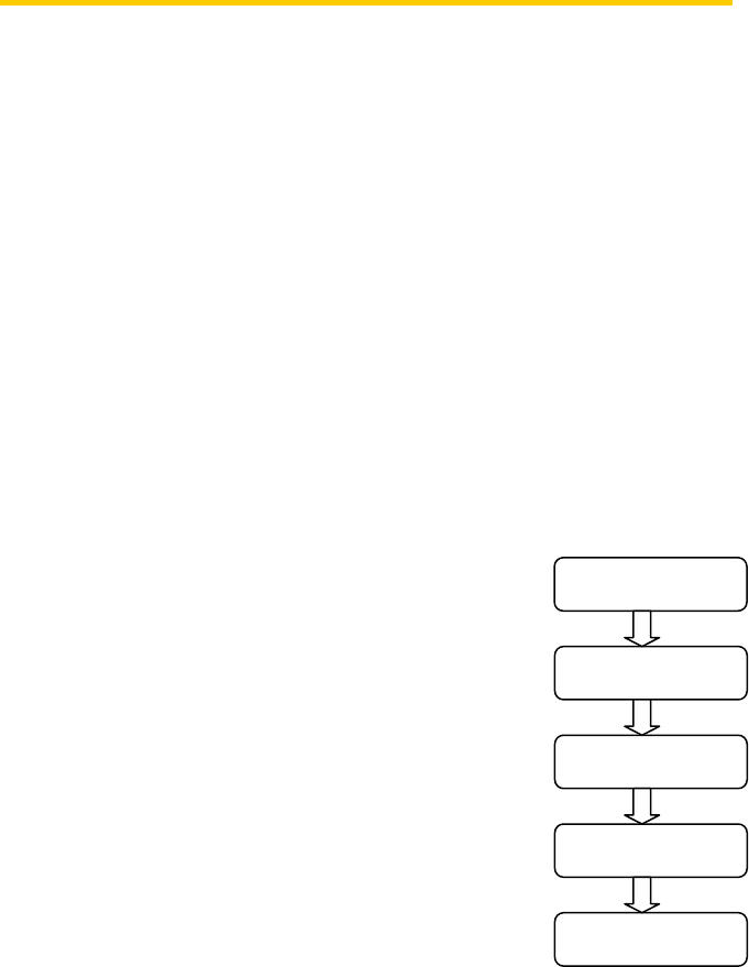
2. Starting-up display sequence: Once the PV power
is sufficient, Inverter displays information as
shown in the flow chart to the right.
3. Change display information: During normal
operation, LCD shows the detail of PV-Inverter.
On the other hand, the display is setup to
automatically indicate the supplying power to the
grid. Each subsequent press changes the display
by press the “Function” key on the front panel.
Model
Waitin
g
Checking= xxxS
Normal State
Pac =xxxx.xW
Information during
start-up
4. Hold display: If you want to hold a specific display.
Edition 1.6E, 2010/06 20
Repeatedly press the function key until the desired display is reached.
Release the key and press again for more than 2 second until you see
“Lock”, release the key; the information remains on the display. To
change the display again, please press the key as indicated in above
section 3. Change display information.
5. LCD backlight control: To save power, the LCD display’s backlight
automatically turns off after 10 seconds. To enable it, press the
“Function” key again.
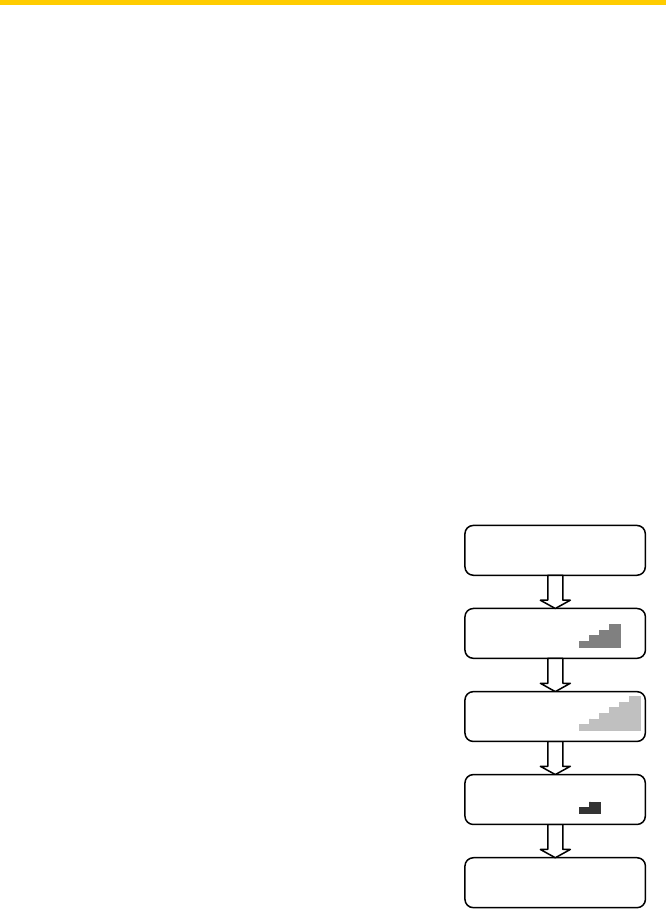
6. Contrast control: A natural phenomenon of LCD displays is the
background color is darker at higher temperatures. At higher
temperatures, the characters may not be easily identified. In this case,
the adjust the contrast as follows:
a. Press the “Function” key repeatedly until
“Contrast” shows in the display. Contrast
b. Hold the “Function” key down for more
than 2 seconds, until display shows “Set
contrast” and a bar graph on the right.
Set Contrast
c. Press the “Function” key repeatedly until
the display’s contrast is acceptable.
d. Release the key for more than 10 seconds,
the display will show “Pac =xxxx.xW”.
e. Setting completed.
Set Contrast
Set Contrast
Pac =xxxx.xW
Lighter
Darker
Done
Contrast setup
21
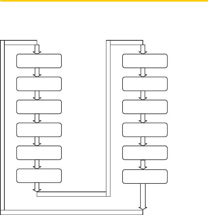
LCD Display Sequence:
Pac =xxxx.xW
Eac=xxxxxxkWh
Vdc=xxx.xV
Iac= x.xA
Frequency=xx.xHz
Model
A1.00
Normal state
Contrast
Set language
Feeding
Total energy
DC-PV voltage
Feeding current
Etoday=xxx.xxKWh Daily energy
AC-Grid freq.
Model name
FW version
Operating status
Contrast Adj.
Set language
Vac=xxx.xV AC-Grid voltage
Edition 1.6E, 2010/06 22
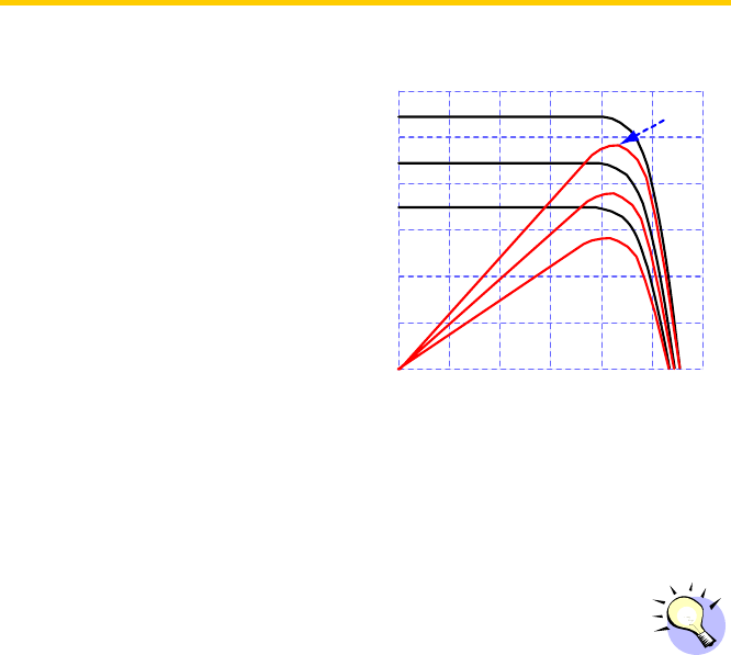
Maximum Power Point Tracking (MPPT)
A good PV inverter must be
able to convert the maximum
power from any PV panel. Due
to its advanced design, Inverter
PV-Inverter can track the
maximum power from your PV
panel in any condition. When the
displayed power on the LCD
output does not change
dramatically, inverter is converting the maximum power from panels.
When the LCD power reading is significantly changes, Inverter is
tracking the power according to the varied sunlight.
IPV (A)
UPV (V)
01020304050
1
2
3
4
5
PPV (W)
25
50
75
100
125
W
Wh
he
en
n
t
th
he
e
P
PV
V
p
pa
an
ne
el
l’
’s
s
o
ou
ut
tp
pu
ut
t
i
is
s
l
lo
ow
w,
,
t
th
he
e
f
fe
ee
ed
di
in
ng
g
D
DC
C-
-p
po
ow
we
er
r
m
ma
ay
y
d
dr
ri
if
ft
t
s
sl
lo
ow
wl
ly
y
a
as
s
d
do
oe
es
s
t
th
he
e
A
AC
C
p
po
ow
we
er
r.
.
I
It
t
i
is
s
b
be
ec
ca
au
us
se
e
P
PV
V-
-I
In
nv
ve
er
rt
te
er
r
i
is
s
t
tr
ra
ac
ck
ki
in
ng
g
m
ma
ax
xi
im
mu
um
m
D
DC
C-
-p
po
ow
we
er
r
c
co
on
nt
ti
in
nu
uo
ou
us
sl
ly
y.
.
1000W/m2
800W/m2
600W/m2
Maximum power point
@ 1000W/m ~ 120W
2
23

6. Inverter Status
Inverter is designed to be user-friendly. Therefore, the status of the Inverter
can be easily understood by reading the information that shown on the front
panel display. All possible messages are shown in the following table.
Display information
Operating conditions In English Description
Normal Working Status
Power off No display PV inverter is totally shutdown, VPV <70V
Standby Standby 70V≦ Input voltage <100V
Initialization & waiting Waiting Input voltage range 100~150V during
start-up. After PV voltage is higher than
100V, inverter is waiting for feeding to grid
Check grid Checking xxxS When PV voltage> 150V, inverter is
checking feeding conditions
Feeding grid, MPPT Normal Inverter is feeding power. After 10 seconds
of this display, LCD will show wattage.
FLASH FLASH FLASH firmware
Monitoring Parameters
Instantaneous Output power Pac =xxxx.xW The real time output power in xxxx W
Accumulated energy
information Eac=xxxxxxkWh Total energy that has been fed to grid since
inverter was installed
Grid voltage Vac = xxx.xV Grid voltage in xxx.x VAC
Grid frequency Frequency=xx.xHz Grid frequency in xx.x Hz
Edition 1.6E, 2010/06 24

Operating conditions In English Description
Feeding current Iac = x.xA Feeding current amount in xx.x A
PV array voltage Vdc = xxx.x V Input voltage from PV array, xxx.x VDC
Daily Energy Etoday=xxx.xxKW
h The accumulated kWh of that day
System Fault
Isolation failure Isolation fault Earth fault of the PV-panels or failure of
surge voltage protection
GFCI active Ground I fault Leakage current detected from ground
conductor is too high
Grid failure Grid fault Grid measured data is beyond the
specification (voltage & frequency)
No utility No Utility Utility is not available
Input voltage too high PV over voltage Input voltage is higher than the maximum
input voltage
Inverter Fault
Consistent failure Consistent Fault The readings of 2 microprocessors are not
consistent. It could be caused by CPU
and/or other circuit do not function well.
Temperature too high Over temperature The internal temperature of inverter is
higher than normal value
Output relay failure Relay Failure The relay between inverter and grid is not
functional
Output DC injection too high DC INJ High Output DC injection is higher than
expected
EEPROM problem EEPROM Failure EEPROM inside has data access problem
Communication failure
between microprocessors SCI Failure The communication between MCU inside
is abnormal
25

Operating conditions In English Description
DC bus voltage is too high High DC Bus The DC BUS voltage is higher than
expected
DC bus voltage is too low Low DC Bus The DC BUS voltage is lower than
expected
2.5V reference voltage inside
problem Ref 2.5V Fault The 2.5V reference inside are abnormal
Output DC sensor abnormal DC Sensor Fault Detection of DC output sensor is abnormal
GFCI detection problem GFCI Failure The GFCI detection circuit is abnormal
System Information
Model display EATON ETN1000
/ETN2000 Inverter model, xkW inverter
LCD contrast Contrast LCD contrast setting
LCD contrast setting Set Contrast Contrast setting of LCD display
LCD display lock Lock Hold the present display message
Waiting for reconnect to grid Reconnect xxxS The time that needs to reconnect grid
power
Firmware version Ver. xx.xx F/W version information
Setting Language Set Language Set up of the display language
Edition 1.6E, 2010/06 26

7. Communications
Inverter is equipped with a powerful communications interface and options.
Use Inverter’s EZ control to monitor the status of your PV-Inverter. Also,
qualified personnel can upgrade the firmware using the RS232 port.
1. RS232: To use the RS232 port, remove the RS232 cover on the bottom
side of Inverter. It is a DB9 socket. The pin definition is
Pin Functional Description
1 N.C.
2 TxD
3 RxD
4 N.C.
5 Common
6 N.C.
7 N.C.
8 N.C.
9 N.C.
N
N.
.C
C.
.
m
me
ea
an
ns
s
“
“N
No
o
C
Co
on
nn
ne
ec
ct
ti
io
on
n”
”
2. Optional communications port: It is a powerful extension that can accept
a special card that designed for communication purpose such as RS485.
The RS485 card can be used to work with Inverter’s EZ logger as
multiple monitoring applications.
3. Firmware upgrade: To up-to-date keep the firmware, use the RS232
port and supplied program to upgrade firmware. To do this, please
contact EATON Customer Service.
27

EATON Contact Information
Telephone: 1300 3 EATON
Web: http://www.Eatonelectric.com.au/
T
To
o
p
pr
re
ev
ve
en
nt
t
r
ri
is
sk
k
o
of
f
d
da
am
ma
ag
ge
e
i
it
t
i
is
s
r
re
ec
co
om
mm
me
en
nd
de
ed
d
t
th
ha
at
t
o
on
nl
ly
y
a
au
ut
th
ho
or
ri
iz
ze
ed
d
p
pe
er
rs
so
on
nn
ne
el
l
p
pe
er
rf
fo
or
rm
m
f
fi
ir
rm
mw
wa
ar
re
e
u
up
pg
gr
ra
ad
de
es
s.
.
Edition 1.6E, 2010/06 28

8. Trouble shooting
In most situations, the Inverter requires very little service. However, if
Inverter is not able to work perfectly, please refer to the following instructions
before calling your local dealer.
z Should any problems arise, the red (Fault) LED on the front panel turns
on and the LCD displays the relevant information. Please refer to the
following table for a list of potential problems and their solutions.
Display Possible actions
Isolation Fault
1. Check the impedance is between PV (+) & PV
(-) and the PV-Inverter is earthed. The
impedance must be greater than 5MΩ
2. If the problem persists please contact Eaton.
Ground I Fault
1. The ground current is too high.
2. Unplug the inputs from the PV generator and
check the peripheral AC system
3. After the cause is cleared, re-plug the PV panel
and check PV-Inverter status.
4. If the problem persists please contact Eaton.
Grid Fault
1. Wait for 5 minutes, if the grid returns to normal,
PV-Inverter automatically restarts.
2. Make sure grid voltage and frequency meet the
specifications
3. If the problem persists please contact Eaton.
System
Fault
No Utility 1. Grid is not connected.
2. Check grid connection cables.
3. Check grid usability.
PV over
Voltage
1. Check the open PV voltage, see if it is greater
than or too close to 450VDC
2. If PV voltage is less than 450VDC, and the
problem still occurs, please contact Eaton.
Inverter
Failure
Consistent
Fault
1. Disconnect PV (+) or PV (-) from the input,
restart the PV-Inverter
2. If it does not work, please Contact Eaton.
29

Over
Temperature
1. The internal temperature is higher than
specified normal value
2. Find a way to reduce the ambient temperature.
3. Or move the inverter to a cooler environment
4. If it is not effective, please contact Eaton.
Relay Failure
DC INJ High
EEPROM
Failure
SCI Failure
High DC Bus
Low DC Bus
Ref 2.5V Fault
DC Sensor
Fault
GFCI Failure
1. Disconnect ALL PV (+) or PV (-)
2. Wait for few seconds
3. After the LCD switches off, reconnect and
check again
4. If the message reappears, please contact
Eaton.
z If there is no display on the panel, please check PV-input connections.
If the voltage is higher than 150V, call your local service.
z During periods of little or no sunlight, the PV-Inverter may continuously
start up and shut down. This is due to insufficient power generated to
operate the control circuits.
Edition 1.6E, 2010/06 30

9. Specifications
Electrical
Model EATON ETN1000 EATON ETN2000
Nominal AC power 1000W 2000W
Max. AC power
(in 10 minutes) 1100W 2200W
Input
Nominal DCV 360VDC 360VDC
Max. open DCV 500VDC 500VDC
MPPT range 150 to 450VDC 150 to 450VDC
Working range 100 to 500VDC 100 to 500VDC
Max. input current 5ADC 10ADC
Output
Operational voltage
range1 (F/W Setting) 206~264 VAC 206~264 VAC
Operational frequency
range2 (F/W Setting) 49.25~50.75Hz 49.25~50.75Hz
Current distortion <3% <3%
Power factor >0.99 >0.99
Maximum η 95% 96%
European η 93% 95%
Environment
Protection degree IP 43
Operating temperature -20 to 55ºC
Humidity 0 to 95%, non-condensing
Heat Dissipation Convection
Power consumption <7W
Acoustic noise <35dBA
Communication & Features
LCD 1-Line, 16 characters
Comm. Interface RS232 standard, RS485 optional
F/W upgrade Yes, via RS232
Mechanical
W×D×H (mm) 305x302x120
Weight (kg) 11.3
Normative references
Grid interface regulation AS4777
Safety AS3100
EMC: EMS/EMI EN 61000-6-2 (2005) / EN 61000-6-3 (2007)
CE LVD: 2006/95/EC EMC: 2004/108/EC
1 Regulation voltage range is 200~270 VAC according to AS4777.
2 Regulation frequency range is 45~55Hz according to AS4777.
31

∗Product specifications are subject to change without notice
Edition 1.6E, 2010/06 32
