Eaton Electrical Magnum Transfer Switch Users Manual
Magnum Transfer Switch to the manual 899bc1d6-1b30-4855-91a1-7fd386d274e7
2015-02-06
: Eaton-Electrical Eaton-Electrical-Magnum-Transfer-Switch-Users-Manual-537209 eaton-electrical-magnum-transfer-switch-users-manual-537209 eaton-electrical pdf
Open the PDF directly: View PDF ![]() .
.
Page Count: 36
- Section 1: Introduction
- Section 2: Receiving, Handling, and Storage
- Section 3: Equipment Description
- Section 4: Installation and Wiring
- Section 5: Operation
- Section 6: Drawout and Fixed Switching Devices
- Section 7: Operation of the Bypass Isolation Transfer Switch
- Section 8: Testing and Problem Solving
- Section 9: Maintenance
- Section 10: Renewal Parts Guide
IB01602011E For more information visit: www.Eaton.com
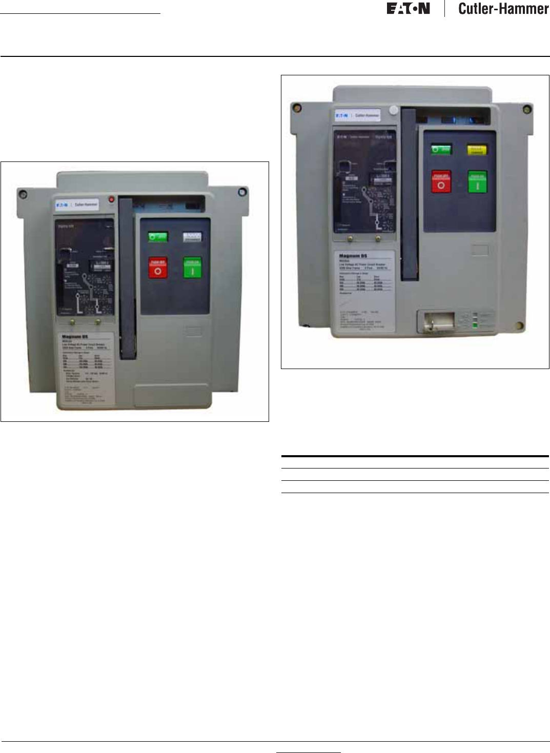
O & M Manual for the Fixed and
Drawout Magnum Transfer Switches
Instruction Booklet
New Information
Description Page
Introduction . . . . . . . . . . . . . . . . . . . . . . . . . . . . . . . . . . . . 3
Receiving, Handling, and Storage . . . . . . . . . . . . . . . . . . . . 10
Equipment Description. . . . . . . . . . . . . . . . . . . . . . . . . . . . 10
Installation and Wiring. . . . . . . . . . . . . . . . . . . . . . . . . . . . 16
Operation . . . . . . . . . . . . . . . . . . . . . . . . . . . . . . . . . . . . 20
Drawout and Fixed Switching Devices . . . . . . . . . . . . . . . . 22
Operation of the Bypass Isolation Transfer Switch . . . . . . . . 25
Testing and Problem Solving . . . . . . . . . . . . . . . . . . . . . . . 29
Maintenance . . . . . . . . . . . . . . . . . . . . . . . . . . . . . . . . . . 31
Renewal Parts Guide . . . . . . . . . . . . . . . . . . . . . . . . . . . . . 33
For more information visit: www.Eaton.com IB01602011E
Instructional Booklet
Page 2Effective: March 2007 Fixed and Drawout Magnum Transfer Switches
Figure 1. Typical Automatic Transfer Switch Equipment Nameplate.
Step 1: Remove any dirt or debris that may have collected during
shipment or installation. NEVER use high pressure blow-
ing air. This could drive dirt or other foreign objects into
electrical or mechanical components which could cause
damage. Use an industrial quality vacuum cleaner to
remove any dirt or foreign objects.
Step 2: Be certain all cable connections are correct and that the
phase rotation of both sources match.
Step 3: Inspect the engine start connections and verify the cor-
rect connection of all control wires.
Step 4: Check all programmable setpoints and adjust as neces-
sary. In addition, adjust any optional accessories as
required.
Step 5: Be certain that the actual lug torque values are in keeping
with the requirements outlined in the instruction book to
insure the integrity of power connections.
Step 6: Check to be sure that all covers and barriers are properly
installed and fastened.
ALL POSSIBLE CONTINGENCIES WHICH MAY ARISE DURING INSTALLATION, OPERATION, OR MAINTENANCE, AND ALL DETAILS AND VARIA-
TIONS OF THIS EQUIPMENT DO NOT PURPORT TO BE COVERED BY THESE INSTRUCTIONS. IF FURTHER INFORMATION IS DESIRED BY THE
PURCHASER REGARDING HIS PARTICULAR INSTALLATION, OPERATION, OR MAINTENANCE OF PARTICULAR EQUIPMENT, CONTACT AN
EATON REPRESENTATIVE.
WARNING
READ AND UNDERSTAND THE INSTRUCTIONS CONTAINED HEREIN-
AFTER BEFORE ATTEMPTING TO UNPACK, ASSEMBLE, OPERATE,
OR MAINTAIN THIS EQUIPMENT.
HAZARDOUS VOLTAGES ARE PRESENT INSIDE TRANSFER SWITCH
ENCLOSURES THAT CAN CAUSE DEATH OR SEVERE PERSONAL
INJURY. FOLLOW PROPER INSTALLATION, OPERATION, AND MAIN-
TENANCE PROCEDURES TO AVOID THESE VOLTAGES.
TRANSFER SWITCH EQUIPMENT COVERED BY THIS INSTRUCTION
BOOK IS DESIGNED AND TESTED TO OPERATE WITHIN ITS NAME-
PLATE RATINGS. OPERATION OUTSIDE OF THESE RATINGS MAY
CAUSE THE EQUIPMENT TO FAIL RESULTING IN DEATH, SERIOUS
BODILY INJURY, AND/OR PROPERTY DAMAGE. ALL RESPONSIBLE
PERSONNEL SHOULD LOCATE THE DOOR MOUNTED EQUIPMENT
NAMEPLATE AND BE FAMILIAR WITH THE INFORMATION PROVIDED
ON THE NAMEPLATE. A TYPICAL EQUIPMENT NAMEPLATE IS
SHOWN IN FIGURE 1.
NOTICE
A FINAL INSPECTION OF THE EQUIPMENT SHOULD BE PERFORMED
PRIOR TO ENERGIZING THE TRANSFER SWITCH.
E
Automatic Transfer Switch
Cat No: ATVIMGB33200XRU 11/04
GO No: 1of1
Item 1
Poles: 3 Amps: 3200 Volt: 120/600 VAC
Phase: 3 Hertz: 60 Wire: 4
IB01602011E For more information visit: www.Eaton.com
Instructional Booklet
Effective: March 2007 Page 3
Fixed and Drawout Magnum Transfer Switches
Section 1: Introduction
1.1 Preliminary Comments and Safety Precautions
This technical document is intended to cover most aspects associ-
ated with the installation, application, operation, and maintenance
of transfer switch equipment with ratings from 800 through
3200 amperes (A), except for the specific logic used to control
the equipment. It is provided as a guide for authorized and quali-
fied personnel only. Please refer to the specific WARNING and
CAUTION in Section 1.1.2 before proceeding. If further informa-
tion is required by the purchaser regarding a particular installation,
application, or maintenance activity, contact an Eaton representa-
tive. For information associated with the control, refer to the sep-
arate instruction book pertaining to the logic package installed in
the switch.
1.1.1 Warranty and Liability Information
No warranties, expressed or implied, including warranties of fit-
ness for a particular purpose of merchant-ability, or warranties
arising from course of dealing or usage of trade, are made regard-
ing the information, recommendations and descriptions contained
herein. In no event will Eaton be responsible to the purchaser or
user in contract, in tort (including negligence), strict liability or
otherwise for any special, indirect, incidental or consequential
damage or loss whatsoever, including but not limited to damage or
loss of use of equipment, plant or power system, cost of capital,
loss of power, additional expenses in the use of existing power
facilities, or claims against the purchaser or user by its customers
resulting from the use of the information and descriptions con-
tained herein.
1.1.2 Safety Precautions
All safety codes, safety standards, and/or regulations must be
strictly observed in the installation, operation, and maintenance of
this device.
.
1.2 General Information
Transfer switches are used to protect critical electrical loads
against loss of power. The Source 1 power source of the load is
backed-up by a Source 2 power source. A transfer switch is con-
nected to both the Source 1 and Source 2 power sources and sup-
plies the load with power from one of these two sources. In the
event that power is lost from the Source 1 power source, the
transfer switch transfers the load to the Source 2 power source.
This transfer can be automatic or manual, depending upon the
type of transfer switch equipment being used. Once Source 1
power is restored, the load is automatically or manually trans-
ferred back to the Source 1 power source, again depending upon
the type of transfer equipment being used (Figure 2).
In addition, the Eaton closed transition transfer switch may be
applied where it is desirable to avoid any momentary power inter-
ruptions. Although the closed transition switch is not a substitute
for an uninteruptable power source (UPS), it does eliminate power
interruptions to loads except to those caused by power sources or
equipment external to the transfer switch. If both sources are
acceptable as determined by the IQ Transfer logic, a make-before-
break transfer is performed during a transfer test or retransfer
operation.
1.2.1 Transfer Switch Types
There are four types of transfer switch equipment.
Automatic Transfer Switch
Automatic transfer switches (ATSs) automatically perform the
transfer function. They consist of three basic elements:
1. Main contacts to connect and disconnect the load to and from
the source of power.
2. Intelligence/supervisory circuits to constantly monitor the con-
dition of the power sources and thus provide the intelligence
necessary for the switch and related circuit operation.
3. A transfer mechanism to effect the transfer of the main con-
tacts from source to source.
WARNING
THE WARNINGS AND CAUTIONS INCLUDED AS PART OF THE PRO-
CEDURAL STEPS IN THIS DOCUMENT ARE FOR PERSONNEL SAFETY
AND PROTECTION OF EQUIPMENT FROM DAMAGE. AN EXAMPLE
OF A TYPICAL WARNING LABEL HEADING IS SHOWN ABOVE TO
FAMILIARIZE PERSONNEL WITH THE STYLE OF PRESENTATION.
THIS WILL HELP TO INSURE THAT PERSONNEL ARE ALERT TO
WARNINGS, WHICH APPEAR THROUGHOUT THE DOCUMENT. IN
ADDITION, CAUTIONS ARE ALL UPPER CASE AND BOLDFACE.
CAUTION
COMPLETELY READ AND UNDERSTAND THE MATERIAL PRESENTED
IN THIS DOCUMENT BEFORE ATTEMPTING INSTALLATION, OPERA-
TION, OR APPLICATION OF THE EQUIPMENT. IN ADDITION, ONLY
QUALIFIED PERSONS SHOULD BE PERMITTED TO PERFORM ANY
WORK ASSOCIATED WITH THE EQUIPMENT. ANY WIRING
INSTRUCTIONS PRESENTED IN THIS DOCUMENT MUST BE FOL-
LOWED PRECISELY. FAILURE TO DO SO COULD CAUSE PERMA-
NENT EQUIPMENT DAMAGE.
WARNING
THE CLOSED TRANSITION PRODUCT CONTAINS A SPECIAL CON-
TACT ARRANGEMENT (OVERLAPPING CONTACTS). MISUSE CAN
RESULT IN DEATH, SEVERE PERSONAL INJURY, AND/OR PROPERTY
DAMAGE.
For more information visit: www.Eaton.com IB01602011E
Instructional Booklet
Page 4Effective: March 2007 Fixed and Drawout Magnum Transfer Switches
Basic Transfer Switch (Power Panel)
The basic transfer switch is designed for use with customer fur-
nished logic. It is similar in design to the automatic version,
except the intelligence circuit (logic panel) and voltage selection
panel are omitted. All control devices are the customer’s
responsibility.
Figure 2. Typical Load Transfer Switch (Switching Device Type)
Schematic.
Non-Automatic Transfer Switch (Electrically Operated)
Non-automatic transfer switches are manually initiated, electrically
operated devices for applications where automatic load transfer is
not required.
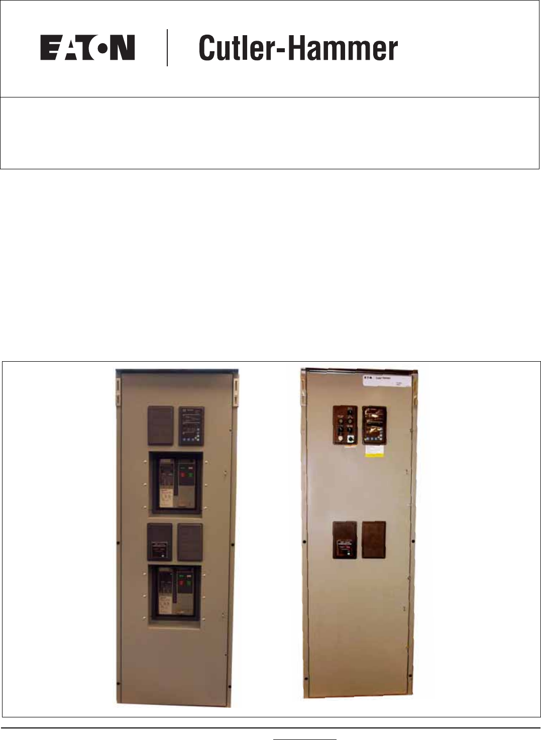
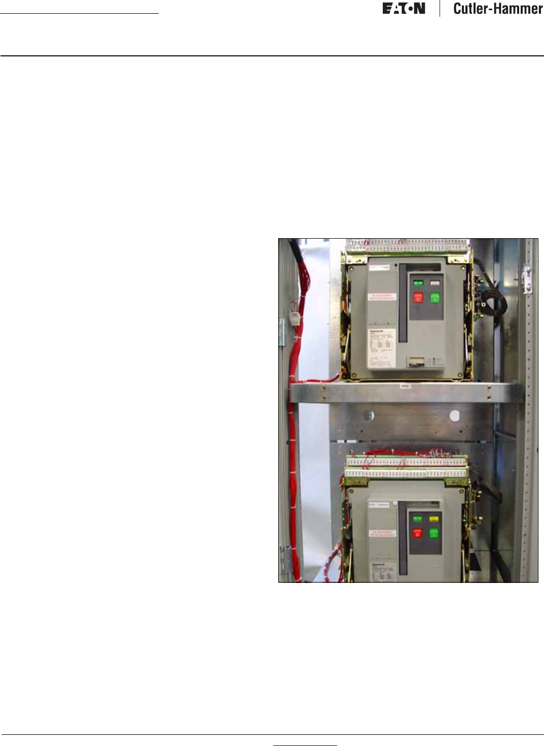
Bypass Isolation Transfer Switch
The bypass isolation switch is designed for applications where
maintenance, inspection, and testing must be performed while
maintaining continuous power to the load (Figures 3 and 4). This
is typically required in critical life support systems and standby
power situations calling for safe system maintenance with no
power disruptions. Such a design allows for the quick removal of
the different switching devices for inspection, maintenance, or
replacement.
The ATS, non-automatic transfer switch (electrically operated),
and bypass isolation transfer switch are the available types for the
configuration described in this manual.
Operation of the ATS and the bypass isolation switch only are dis-
cussed in this manual (Sections 5 and 7 respectively).
1.2.2 Design Configuration
The Eaton transfer switch is a rugged, compact design utilizing
insulated case switches or insulated case circuit breakers to trans-
fer essential loads from one power source to another. Open tran-
sition switching devices are interlocked to prevent both switching
devices from being closed at the same time. The versatile design,
in addition to standard transfer functions, offers an optional inte-
gral thermal and short circuit protection in either or both switching
devices.
The switching devices are in a compact vertical arrangement. The
logic can be easily disconnected from the switching device with-
out disturbing critical connections. The enclosure is free standing,
and, by using the specially supplied cleats, the switch is seismic
approved (Option 42). The terminals are mounted in the rear of
the switch, permitting rear, top, bottom, or side cable or bus bar
entrance.
The switching devices have a high withstand rating (Table 1). The
high-speed, stored-energy switching mechanism guarantees a
transfer time of less than 5 cycles.
Figure 3.Typical Bypass Isolation Switch.
Source 1
Source 2
Load
IB01602011E For more information visit: www.Eaton.com
Instructional Booklet
Effective: March 2007 Page 5
Fixed and Drawout Magnum Transfer Switches
Figure 4.Typical Bypass Isolation Switch Schematic.
Table 1. Withstand Ratings
Tested in accordance with UL1008.
Eaton Drawout Magnum Transfer Switch will coordinate with a power switching device short time rating. Contact factory for details.
SOURCE 1
SOURCE 1
SOURCE 1
SOURCE 1
BYPASS
SOURCE 1
SOURCE 1
SOURCE 1
AVAILABLE
SOURCE 2
ISOLATED
ISOLATED
POSITION
SOURCE 2
POSITION
SOURCE 2
AVAILABLE
SOURCE 2 SOURCE 2
SOURCE 2
INCOMING
ATS
BYPASS
BYPASS
ATS
LOAD
SOURCE 2
BYPASS
INCOMING
A
A
RATING WHEN USED WITH UPSTREAM CIRCUIT BREAKER RATING WHEN USED WITH UPSTREAM FUSE
Transfer Switch
Amp Rating 3 Cycle
600V
(kA)
30 Cycle
600V
(kA)
800 100 85
1000 100 85
1200 100 85
1600 100 85
2000 100 85
2500 100 85
3200 100 85
For more information visit: www.Eaton.com IB01602011E
Instructional Booklet
Page 6Effective: March 2007 Fixed and Drawout Magnum Transfer Switches
1.3 Magnum Fixed and Drawout Switching Devices
1.3.1 General Magnum Switching Device
The Magnum switching devices used in the Magnum transfer
switches are air switching devices utilizing an electronic tripping
system. They are available in both fixed and drawout versions,
both of which are used in the Magnum transfer switch depending
on the specific transfer switch ordered.
Figure 5. The Magnum Fixed Switching Device.
Figure 6. The Magnum Drawout Switching Device.
The Magnum transfer switches are available in the following con-
figurations:
Table 2. Magnum Transfer Switch Configurations
All Magnum switching devices are 100% rated, Underwriters Lab-
oratories (UL) listed, and are built and tested in an ISO 9002 certi-
fied facility to applicable NEMA, ANSI, IEEE, and UL standards.
For more information on Magnum switching devices, consult the
Magnum switching device manual supplied with the transfer
switch.
The main difference between the fixed and drawout versions of
the Magnum switching devices used in the Magnum transfer
switch is the mounting method. Fixed switching devices are
bolted directly into the transfer switch frame while drawout
switching devices are mounted in an extendable carriage within
the transfer switch, allowing the switching device to be “drawn
out” for service, maintenance, and/or replacement.
NUMBER OF
SWITCHING DEVICES SWITCHING DEVICE
TYPE
2Fixed
2 Drawouts
4 Drawouts

IB01602011E For more information visit: www.Eaton.com
Instructional Booklet
Effective: March 2007 Page 7
Fixed and Drawout Magnum Transfer Switches
Figure 7. Fixed Switching Device for the Magnum Transfer
Switch.
Figure 8. Drawout Switching Device Installed in the Magnum
Transfer Switch.
1.3.2 Magnum Drawout Switching Devices
The Magnum drawout switching device is a design having three
positions with the compartment door closed (CONNECT, TEST,
DISCONNECT) and one position out of its compartment on the
extendable carriage rails (REMOVE). The Magnum drawout
switching device is equipped with both primary and secondary dis-
connects to provide for the drawout functioning. The operating
mechanism is a two-step, stored energy mechanism, either manu-
ally or electrically operated. When withdrawn on the extendable
carriage rails, Magnum switching devices can be inspected, acces-
sory items added, and minor maintenance performed. The inside
of the compartment can also be inspected with the switching
device withdrawn on the extendable carriage rails.
Figure 9. Drawout Switching Device Fully Extended from the
Magnum Transfer Switch.
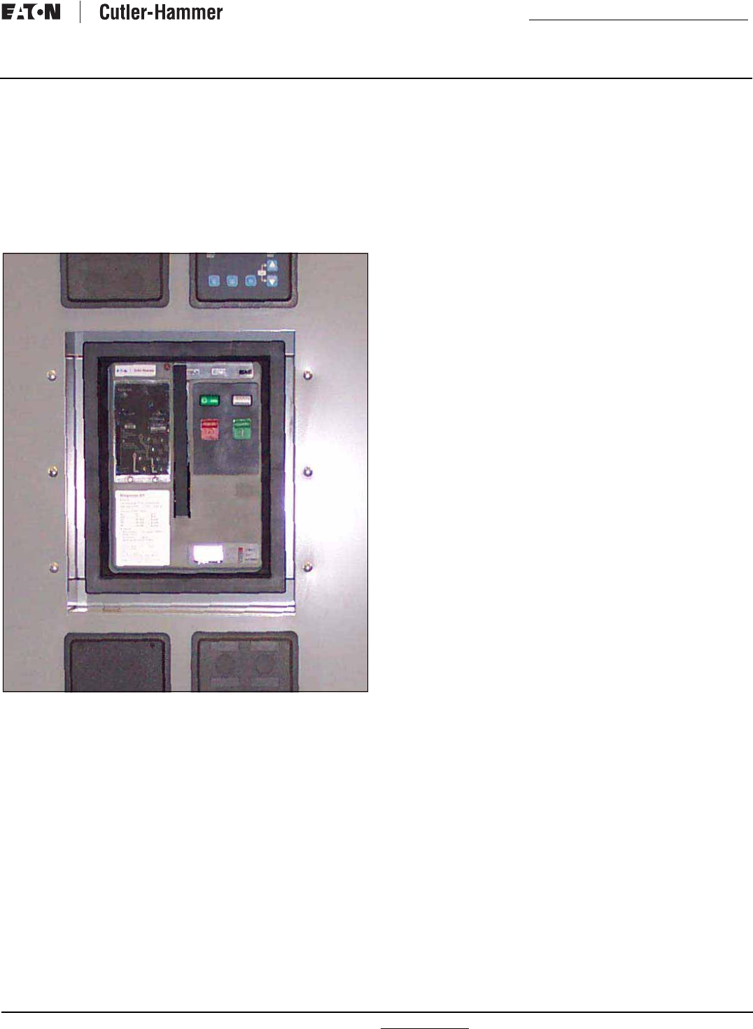
1.3.3 Magnum Fixed Switching Devices
The Magnum fixed type switching device differs from the drawout
version in that it has no levering device, primary disconnects, and
secondary disconnects.
Figure 10. Primary and Secondary Connections on a Magnum
Fixed Switching Device.
PRIMARY CONNECTIONS
SECONDARY CONNECTIONS
For more information visit: www.Eaton.com IB01602011E
Instructional Booklet
Page 8Effective: March 2007 Fixed and Drawout Magnum Transfer Switches
In addition, a fixed switching device does not have a standard fea-
ture to hold the switching device in a “trip-free” position.
Magnum fixed switching device terminals have holes for making
bolted horizontal primary bus connections. Adapters are available
for making vertical primary bus connections. Secondary connec-
tions can be made through standard terminal blocks or a special
connector compatible with the drawout switching device’s type
secondary connector. Both secondary connection devices are
mounted at the top front of the switching device.
The Magnum fixed switching devices have two mounting feet,
one on each side, to permit the switching device to be securely
mounted to the transfer switch frame. Each mounting foot has
two slotted mounting holes to facilitate mounting.
1.4 Transfer Switch Catalog Number Identification
Transfer switch equipment catalog numbers provide a significant
amount of relevant information that pertains to a particular piece
of equipment. The catalog number identification table (Table 3)
provides the required interpretation information. An example for
an open transition switch is offered to initially simplify the pro-
cess.
Example: Catalog Number (circled numbers correspond to position
headings in Table 3).
The catalog number ATVIMGB33200XRU describes an ATS with
the switching devices mounted vertically in the enclosure. The
intelligence, represented by the ATC-400/ATC-600/ATC-800, is a
microprocessor-based logic package. The Magnum Breaker is used
as the switching device and is a 3-pole molded case breaker for
each source. The continuous current rating of this equipment is
3200 A and is applicable at 480/277 Vac, 60 Hz. The transfer
switch equipment is enclosed in a NEMA 3R enclosure and is
listed for Underwriters Laboratories (UL) and Canadian Standards
Association (CSA) applications.
IB01602011E For more information visit: www.Eaton.com
Instructional Booklet
Effective: March 2007 Page 9
Fixed and Drawout Magnum Transfer Switches
Table 3. Transfer Switch Catalog Number Explanation.
ATV I G B 3 3200 RXU
M
TYPE
ORIENTATION
LOGIC
FRAME
SWITCH
POLES
AMPERE
RATING
VOLTAGE
ENCLOSURE
TYPE
LISTING
LOGIC
Position 4
I = IQ Transfer
4 = ATC-400
E = Electro Mechanical
TYPE
Position1-2
AT = Automatic
CT = Closed Transition
BI = Bypass Transition
CB = Closed Transition/
Bypass Isolation
NT = Non Auto
ORIENTATION
Position 3
V = Vertical
FRAME
Position 5-6
Molded Cases
Magnum DS MG
SWITCH
Position 7
A = Fixed Mount,
Molded Case Switch (MCS Both)
B = Fixed Mount,
Molded Case Circuit Breaker (HCCB Both)
C = Fixed Mount,
MCCB Normal, MCS Emergency
D = Fixed Mount,
MCS Normal, MCCB Emergency
E = Drawout, MCS Both
F = Drawout, MCCB Both
G = Drawout, MCCB Normal,
MCS Emergency
H = Drawout, MCS Normal,
MCCB Emergency
POLES
Position 8
2 = 2 Poles
3 = 3 Poles
4 = 4 Poles
AMPERES
Position 9-12
0200 = 200A
0300 = 300A
0400 = 400A
0600 = 600A
0800 = 800A
1000 = 1000A
1200 = 1200A
1600 = 1600A
2000 = 2000A
2500 = 2500A
3200 = 3200A
ENCLOSURE
Position 14
K = Open
S = NEMA 1
R = NEMA 3R
T = Thru Door
Design
LISTING
Position 15
U = UL Listed,
CSA Listed
①
Contact factory for availability
①
VOLTAGE
Position 13
A = 120 V 60 Hz 3 Phase 3 Wire
B = 208/120 60 Hz 3 Phase 4 Wire
E = 600 V 60 Hz 3 Phase 3 Wire
E = 600 V 60 Hz 3 Phase 4 Wire
G = 220/127 V 50 Hz 3 Phase 4 Wire
G = 220/110 V 50/60 Hz 1 Phase 3 Wire
H = 380/220 V 50 Hz 3 Phase 4 Wire
K = 600 V 50 Hz 3 Phase 4 Wire
M = 230 V 50 Hz 3 Phase 3 Wire
M = 230 V 50 Hz 1 Phase 3 Wire
N = 401/230 V 50 Hz 3 Phase 4 Wire
O = 415/240 V 50 Hz 3 Phase 4 Wire
W = 240/120 V 60 Hz 1 Phase 3 Wire
W = 240 V 60 Hz 3 Phase 3 Wire
W = 240/120 V 60 Hz 3 Phase 4 Wire Hi-Leg
W = 230/115 V 60 Hz 1 Phase 3 Wire
X = 480 V 60 Hz 3 Phase 3 Wire
X = 480/277 V 60 Hz 3 Phase 4 Wire
X = 480/240 V 50 Hz 1 Phase 2 Wire
Z = 346/220 V 50 Hz 3 Phase 4 Wire
Magnum
Bypass, Automatic and Non-automatic
Transfer Switches
800-3200 Amperes
USING THE STYLE IDENTIFICATION GUIDE
The Style Identification Guide provides an overview of the ten basic style/feature
categories which generate the 15 digit Genswitch catalog number.
For more information visit: www.Eaton.com IB01602011E
Instructional Booklet
Page 10 Effective: March 2007 Fixed and Drawout Magnum Transfer Switches
Section 2: Receiving, Handling, and Storage
2.1 Receiving
Every effort is made to ensure that the transfer switch equipment
arrives at its destination undamaged and ready for installation.
Crating and packing is designed to protect internal components as
well as the enclosure. Transfer switch enclosures are skid
mounted and suited for fork lift movement. Care should be exer-
cised, however, to protect the equipment from impact at all times.
Do not remove the protective packaging until the equipment is at
the installation location and ready for installation.
When the transfer switch equipment reaches its destination, the
customer should inspect the shipping container for any obvious
signs of rough handling and/or external damage incurred during
transportation. Record any external and internal damage observed
for reporting to the transportation carrier and Eaton, once a thor-
ough inspection is completed. All claims should be as specific as
possible and include the Shop Order and General Order numbers.
A shipping label is affixed to the top of the shipping container
which includes a variety of equipment and customer information,
such as General Order Number (GO #) and Catalog Number
(Cat #). Make certain that this information matches other ship-
ping paper information.
Each transfer switch enclosure is bolted to a rigid wooden pallet.
The pallet is open at two ends for movement by a fork lift. The
shipment is secured and further protected with shrink wrap. Do
not discard the packing material until the equipment is ready for
installation.
A plastic bag of documents will be found within the enclosure,
usually attached to the inside of the door. Important documents,
such as test reports, wiring diagrams, and appropriate instruction
leaflets, are enclosed within the bag and should be filed in a safe
place.
2.2 Handling
As previously mentioned, the transfer switch equipment is pack-
aged for fork lift movement. Protect the equipment from impact
at all times and DO NOT double stack. Once the equipment is at
the installation location and ready for installation, the packaging
material can be removed. Once the enclosure is unbolted from the
wooden pallet, it can be installed using the lifting provision located
on the top of the structure. Be careful not to damage the top or
bottom enclosure mounting flanges. Refer to Section 4 of this
manual for specific installation instructions.
2.3 Storage
Although well packaged, this equipment is not suitable for storage
outdoors. The equipment warranty will not be applicable if there
is evidence of outdoor storage. If the equipment is to be stored
indoors for any period of time, it should be stored with its protec-
tive packaging material in place. Protect the equipment at all
times from excessive moisture, construction dirt, corrosive condi-
tions, and other contaminants.
It is strongly suggested that the package-protected equipment be
stored in a climate controlled environment of -20° to 85°C
(-4° to 185°F) with a relative humidity of 80% or less. DO NOT,
under any circumstances, stack other equipment on top of a trans-
fer switch equipment enclosure, whether packaged or not.
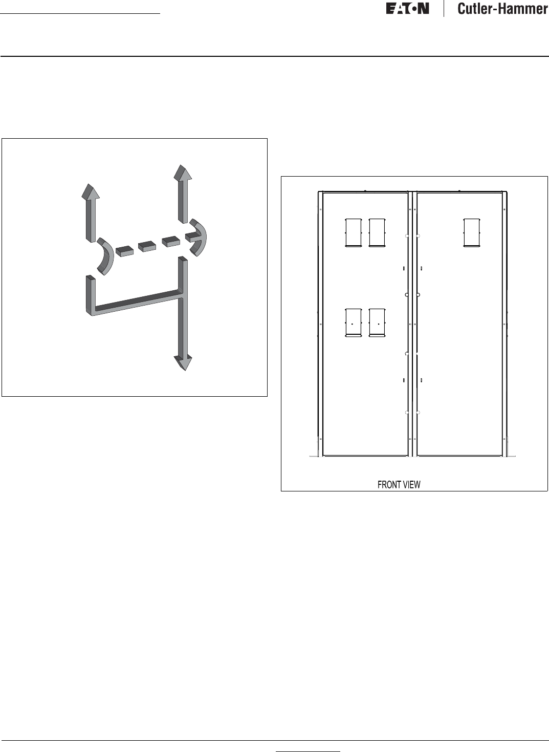
Section 3: Equipment Description
3.1 General
This Eaton transfer switch equipment is available in four different
configurations:
•ATS (Closed and Open transition);
•Non-Automatic (Electrically Operated) (Open Transition Only);
•Bypass Isolation Transfer Switch (Open and Closed Transition);
and
•Power Panel.
Refer to Section 1 for a discussion of all four types. Each transfer
switch is usually supplied in an enclosure, although unmounted
sub-assemblies can be supplied for mounting by the customer.
The enclosed ATS is the only specific type that will be discussed
in this section.
Figure 11. Typical Power Panel (Open Transition Shown).
The enclosed ATS consists of three basic panels interconnected
through connector plugs and mounted in an enclosure:
•Power Panel;
•Voltage Selection Panel; and
•Logic Panel
•ATC-600 (open transition only)
•ATC-800 (closed transition only).
IB01602011E For more information visit: www.Eaton.com
Instructional Booklet
Effective: March 2007 Page 11
Fixed and Drawout Magnum Transfer Switches
The components comprising the three panels are installed in accor-
dance with the specific requirements of the circuit being controlled.
Each transfer switch is, therefore, tailor-made to a specific applica-
tion.
3.2 Power Panel
The power panel consists of a means for making load, power, and
neutral connections. The main contacts and the transfer mecha-
nism are all on one steel frame (Figure 12). The actual power con-
nections are shown in Figure 13.
Figure 12. Insulated Case Switching Device.
3.2.1 Main Contacts
The main contacts connect and disconnect the load to and from
the different power sources. High withstand insulated case
switches are the main contacts for the Source 1 and Source 2
power sources in standard, unmodified ATSs. Optional integral
thermal and short circuit protection in either or both switching
devices is available (Section 3.6). These continuous duty devices
are rated for all classes of loads. In addition, they have high
dielectric strength, heavy-duty switching and withstand capabili-
ties, and high interrupting capacity.
3.2.2 Switch Interlocks (Open Transition Only)
Eaton transfer switches are mechanically and electrically inter-
locked to prevent the two sets of main contacts from being closed
simultaneously.
3.2.3 Drawout Interlocks
The standard closed transition ATS is not provided with a
mechanical interlock. All bypass switching devices are mechani-
cally interlocked to the drawout mechanism to ensure that the
switching device is always open when connecting or disconnect-
ing it from the line and load stabs when in the bypass mode.
All open transition switching devices are mechanically interlocked
to the drawout mechanism to ensure that the switching device is
always open when connecting or disconnecting it from the line
and load stabs.
The switching device will close only in the DISCONNECT, TEST,
and CONNECT positions.
For more information visit: www.Eaton.com IB01602011E
Instructional Booklet
Page 12 Effective: March 2007 Fixed and Drawout Magnum Transfer Switches
3.2.4 TRANSFER MECHANISM
The transfer switch uses Eaton Magnum insulated case switching
devices and insulated case switches with a stored-energy mecha-
nism. An electrical operator automatically recharges the mecha-
nism after the switching device has been closed, and an indicator
on the switch shows whether it is in the OPEN or CLOSED posi-
tion and the status of the stored energy mechanism.
The switching device is closed by energizing a solenoid that
releases the spring mechanism. A shunt trip will open the switch-
ing device if energized.
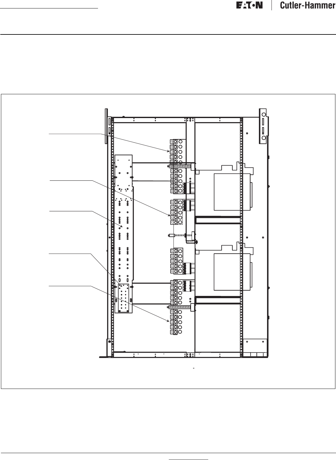
Figure 13. Terminal Connections for a Typical Drawout Transfer Switch (800-3200A Closed Transition Shown).
SOURCE 1
CABLE
CONNECTIONS
LOAD CABLE
CONNECTIONS
GROUND
CABLE
CONNECTIONS
SOURCE 2
CABLE
CONNECTIONS
LEFT SIDE VIEW (WITH PANELS REMOVED)
NEUTRAL CABLE
CONNECTIONS
IB01602011E For more information visit: www.Eaton.com
Instructional Booklet
Effective: March 2007 Page 13
Fixed and Drawout Magnum Transfer Switches
3.2.5 Drawout Mechanism
The drawout mechanism is described in detail in Section 6
(Figure 14).
Figure 14. Drawout Mechanism (Closed Transition Shown)
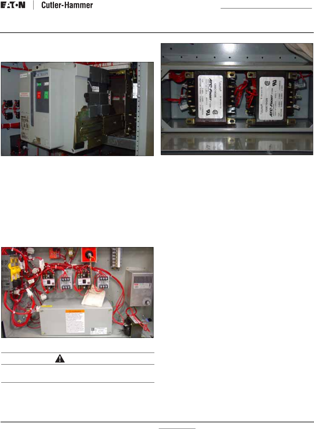
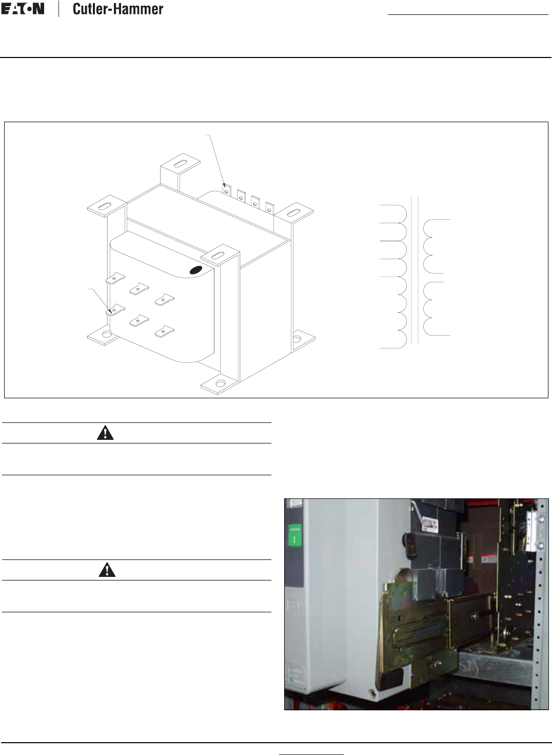
3.3 Voltage Selection Panel
3.3.1 North American Voltage Selection (120, 208, 240, 480,
and 600 V, 60 Hz)
The North American market voltage selection panel consists of
multi-tap transformers, contained in a steel case mounted in the
transfer switch enclosure (Figure 15). The cover has “teardrop”
holes for the screws to allow easy access to the transformers.
The voltage is selected by simply removing the wires from the
default primary taps of both transformers and installing them on
the primary taps for the desired voltage. Taps are provided for
120 to 600 Vac to satisfy any required North American market
application voltage. The factory default position is 600 Vac.
Figure 15. Voltage Selection Panel
Figure 16. North American Market Voltage Selection Terminals
(Shown Connected to the 120 Vac Taps).
3.3.2 International Voltage Selection (208, 220, 240, 380, 415,
and 600 V 50-60 Hz).
The international market voltage selection panel is a multi-tap,
enclosed transformer mounted in the transfer switch enclosure.
Seven front accessible voltage taps from 208 to 600 Vac satisfy
any required international market application voltage. A quick-
change capability from one voltage to another is provided by a
small disconnect plug. The factory default position is 600 VAC.
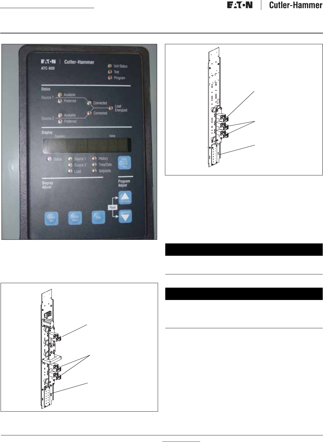
3.4 Logic Panel
The logic panel provides the intelligence and supervisory circuits
which constantly monitor the condition of both the Source 1 and
Source 2 power sources, thus providing the required intelligence
for transfer operations (Figure 17). Detailed information is pre-
sented in a separate document:
•ATC-600 Instruction Book (IB ATS-I005 - open transition only)
•ATC-800 Instruction Book (IB ATS-CI03 - closed transition only)
WARNING
WHEN CHANGING THE SELECTED VOLTAGE, THE POWER MUST BE
REMOVED FROM THE TRANSFER SWITCH AND THE WIRES MUST
BE MOVED ON THE TAPS OF BOTH TRANSFORMERS.
For more information visit: www.Eaton.com IB01602011E
Instructional Booklet
Page 14 Effective: March 2007 Fixed and Drawout Magnum Transfer Switches
Figure 17. ATC-800.
3.5 Neutrals
All 2-pole and 3-pole transfer switches are equipped with 100%
rated neutral connections (Figures 18 and 19). Different lug con-
figurations are available (See Option 21A).
Figure 18. Neutral SE with Ground Fault.
Figure 19. Solid Neutral.
3.6 Features
Switch options, which are not part of the logic scheme, are avail-
able to meet a variety of other application requirements. Options
are numbered with an associated description. More detailed selec-
tions, which must be made within a specific option number, are
identified by letters. For available options associated with the
logic scheme, refer to the specific logic document associated with
the type of logic selected.
14. Relay Auxiliary Contacts
Provides Form “C” relay auxiliary contacts.
E. Source 1 Available: Provides one Form “C” relay auxiliary con-
tact. The relay is energized when Source 1 is available.
F. Source 2 Available: Provides one Form “C” relay auxiliary con-
tact. The relay is energized when Source 2 is available.
Load
Connections
Source
Connections
Ground
Connections
NOTICE
OPTIONS ARE UL LISTED, EXCEPT AS NOTED, WHEN SUPPLIED ON
UL LISTED SWITCHES. IF AN OPTION IS SELECTED WHICH IS NOT
UL LISTED, THE SWITCH WILL NOT HAVE A UL LABEL.
NOTICE
NOT ALL OPTIONS ARE AVAILABLE FOR ALL TRANSFER SWITCH
CONFIGURATIONS. IF IN DOUBT, CHECK PRICE LIST 29-920 FOR
THE AVAILABILITY OF OPTIONS FOR A SPECIFIC TRANSFER
SWITCH DESIGN. THE OPTION NUMBERS USED HERE CORRE-
SPOND TO THE NUMBERS USED IN THE PRICE LIST.
Load
Connections
Source
Connections
Ground
Connections

IB01602011E For more information visit: www.Eaton.com
Instructional Booklet
Effective: March 2007 Page 15
Fixed and Drawout Magnum Transfer Switches
15. Auxiliary Contacts
Position indication contacts provide Form “A and “B” position con-
tacts.
E. Source 1 Position: Provides one Form “A” and one Form “B”
contact per customer connection.
F. Source 2 Position: Provides one Form “A” and one Form “B”
contact for customer connection.
16. Integral Overcurrent Protection
Provides thermal-magnetic overcurrent protection integral to the
power switching device(s). All Feature 16 options include a
“Lockout” function. If the power switching device trips on an
overcurrent condition, then “Lockout” is displayed on the ATS
Controller display and automatic operation is prevented until the
appropriate source is manually reset.
B. Both Power Source Switching Devices: Provides integral over-
current protection on both Source 1 and Source 2 power
switching devices.
E, Source 2 Power Switching Device: Provides integral overcur-
rent protection on the Source 2 power switching device only.
N. Source 1 Power Switching Device: Provides integral overcur-
rent protection on the Source 1 power switching device only.
18. Metering and Communications
The IQ Family of microprocessor-based multi-function monitoring
and display devices features the latest technological advances in
metering and communications capabilities. Feature 18 metering
options include all required external devices (CT’s etc.) for a fully
functioning metering system.
O. IQ Analyzer - Source 1 Line Side Metering: Provides an IQ Ana-
lyzer for monitoring the Source 1 line side circuit.
P. IQ Analyzer - Source 2 Line Side Metering: Provides an IQ Ana-
lyzer for monitoring the Source 2 line side circuit.
Q. IQ Analyzer with Selector Switch for Source 1 or Source 2
Line Side Metering: Provides an IQ Analyzer with a source
selector switch for monitoring the Source 1 or Source 2 line
side circuit.
R. IQ DP-4000 - Source 1 Line Side Metering: Provides an IQ DP-
4000 for monitoring the Source 1 line side circuit.
S. IQ DP-4000 - Source 2 Line Side Metering: Provides an IQ DP-
4000 for monitoring the Source 2 line side circuit.
T. IQ DP-4000 with Selector Switch for Source 1 or Source 2
Line Side Metering: Provides an IQ DP-4000 with a source
selector switch for monitoring the Source 1 or Source 2 line
side circuit.
20A. Rear Bus Connections
Provides Source 1, Source 2, and Load Circuit rear accessible bus
stabs with provision for bus bar connection.
21A. Optional Power Cable Connection Terminals
Provides alternate power cable connection terminals. Consult
Eaton for available optional terminal sizes.
37. Service Entrance Rated Transfer Switch
Provides the label “Suitable for use as Service Equipment” and the
features necessary to meet the requirements for the label.
Includes service disconnect with visible indication and neutral
assembly with removable link. Feature 16 must be selected sepa-
rately.
A. Service Equipment Rated Transfer Switch without Ground
Fault Protection: Provides Service Equipment rating for an
application that does not require ground fault protection.
B. Service Equipment Rated Transfer Switch with Ground Fault
Protection: Provides Service Equipment rating for an applica-
tion that requires ground fault protection.
41. Space Heater with Thermostat
Provides a space heater and adjustable thermostat. External con-
trol power is not required.
C. Space Heater with Thermostat - 400 Watts: Provides a
400 Watt space heater with an adjustable thermostat.
42. Seismic Certification
Provides a Seismic Certified Transfer Switch with certificate for
application that is Seismic Zone 4 under the California Building
Code, the Uniform Building Code, and BOCA.
3.7 Enclosure
The rugged steel switch enclosure is supplied with four door
hinges, regardless of enclosure size, to insure proper support of
the door and door mounted devices. The hinges have removable
hinge pins to facilitate door removal. The doors are supplied as
standard with thumbscrew and padlock latches. Cable entry holes
are the customer’s responsibility.
The door is used to mount a variety of lights, switches, and push
buttons, depending upon the options required for a particular
switch. All switch doors are supplied with a heavy duty plastic
accessory panel in place, whether or not external devices are
required. When lights, pushbuttons, or switches are required,
they are normally mounted in the plastic door mounted panel.
Transfer switch enclosures and some internal steel mounting
plates, such as the transformer panel mounting plate, go through
a pre-treatment cleaning system prior to painting to insure a dura-
ble finish. Should the enclosure become scratched and in need of
touch up paint, use ANSI 61. All remaining steel is galvanized.
The standard switch enclosure is NEMA Type 1 for general indoor
use (Table 4).
Table 4. Transfer Switch Equipment Enclosures.
NEMA TYPE DESIGN PROTECTION
1 Indoor Enclosed Equipment
3R Outdoor Rain, Ice Formation

For more information visit: www.Eaton.com IB01602011E
Instructional Booklet
Page 16 Effective: March 2007 Fixed and Drawout Magnum Transfer Switches
3.8 Standards
Eaton transfer switch equipment is listed for application by UL and
CSA. In addition, Eaton ATSs are listed in File E38116 by
UL, Inc., under Standard UL 1008. This standard covers require-
ments for ATSs intended for use in ordinary locations to provide
for lighting and power as follows:
a. In emergency systems, in accordance with articles 517 and
700 in the National Electrical Code (NEC), American National
Standards Institute/National Fire Protection Association
(ANSI/NFPA) 70 and the NFPA No. 76A and/or
b. In stand-by systems, in accordance with article 702 of the
NEC and/or
c. In legally required stand-by systems in accordance with article
701 of the NEC.
Eaton ATSs are available to meet NFPA 110 for emergency and
stand-by power systems, and NFPA 99 for health care facilities
when ordered with the appropriate options.
Since Eaton ATSs utilize specially designed switches and/or
switching devices as the main power switching contacts, these
devices must also be listed under the additional UL Standard
1066. UL utilizes two basic types of listing programs: a) Label
Service and b) Re-examination. UL1066 employs a label service
listing program which requires an extensive follow-up testing pro-
gram for listed devices. Standard UL1008 for ATSs lists devices
under the re-examination program which only requires a continual
physical re-examination of the components used in the product to
insure consistency with the originally submitted device. Follow-up
testing IS NOT required by UL1008.
Representative production samples of switches and switching
devices used in Eaton ATSs are subjected to a complete test pro-
gram identical to the originally submitted devices on an ongoing
periodic basis per UL1066. The frequency of such a re-submittal
can be as often as every quarter for a low ampere device.
Section 4: Installation and Wiring
4.1 General
Eaton transfer switches are factory wired and tested. Installation
requires solidly mounting the enclosed unit and connecting the
power cables and auxiliary pilot circuits. Physical mounting proce-
dures and power cable connections are covered in this section.
All other required wiring or electrical connection references are
covered in a separate Customer Wiring Diagram packaged with
the transfer switch.
Locate the wiring booklet, review it, and keep it readily available
for reference purposes during installation and testing. Once a
transfer switch is properly installed and wired, it should be
mechanically and electrically checked for proper installation and
operation. The procedures for these initial mechanical and electri-
cal checks are outlined in Section 8.1 of this instruction manual.
4.2 Mounting Location
Choose a location that offers a flat, rigid mounting surface capa-
ble of supporting the weight of the enclosed transfer switch
equipment. Avoid locations that are moist, hot, or dusty. How-
ever, Eaton offers enclosure designs that can be used in special
environments. If there are any doubts as to the suitability of the
location, discuss it with your Eaton representative.
Check to make certain that there are no pipes, wires, or other haz-
ards in the immediate area that could create a problem. The pan-
els provide ample room for rear cable entry from top, bottom, and
sides. At no time should cable be routed to retard the action of
relays or cover the logic in a way that restricts adjustments.
Maintain proper electrical clearances between live metal parts and
grounded metal.
For installation and maintenance purposes, the Source 1 and
Source 2 power sources must have an overcurrent protective
device upstream of the transfer switch, unless overcurrent protec-
tion is integral to the switch.
The dimensions of the transfer switch are an important consider-
ation in determining proper location selection.
WARNING
BE CERTAIN THAT THE SOLID STEEL POWER PANEL SHIELDS ARE
PROPERLY INSTALLED BEFORE THE TRANSFER SWITCH EQUIP-
MENT IS PUT INTO SERVICE. THE SHIELD PROVIDES PROTECTION
FROM DANGEROUS VOLTAGES AT THE LINE AND LOAD TERMI-
NALS WHEN THE EQUIPMENT IS IN OPERATION. FAILURE TO DO
SO COULD RESULT IN PERSONAL INJURY OR DEATH.
IB01602011E For more information visit: www.Eaton.com
Instructional Booklet
Effective: March 2007 Page 17
Fixed and Drawout Magnum Transfer Switches
4.3 Unpackaging and Inspection
Proceed with the following four steps:
Step 1: Carefully uncrate the transfer switch. If damage is visible,
please contact your local Eaton sales representative or the
factory.
Step 2: Open the door and visually verify that there are no broken
or damaged components or evidence of distorted metal or
loose wires as a result of rough handling.
Step 3: A label on the door provides specifications for your trans-
fer switch. Verify that these specifications comply with
your requirements.
Step 4: Remove any braces or packing used to protect the trans-
fer switch or internal components during shipping.
4.4 Mounting Procedure
With the enclosed transfer switch equipment unpacked and ready
for mounting, proceed with the following steps:
Step 1: Mounting and cabling access is best provided by remov-
ing side and rear covers (when applicable). See Section
9.3 for cover removal instructions.
Step 2: Gently maneuver the switch into its location using all of
the supplied lift brackets.
Step 3: Bolt the enclosure to the base. Use separate cleats
(Option 42 only) if Seismic Uniform Building Code (UBC)
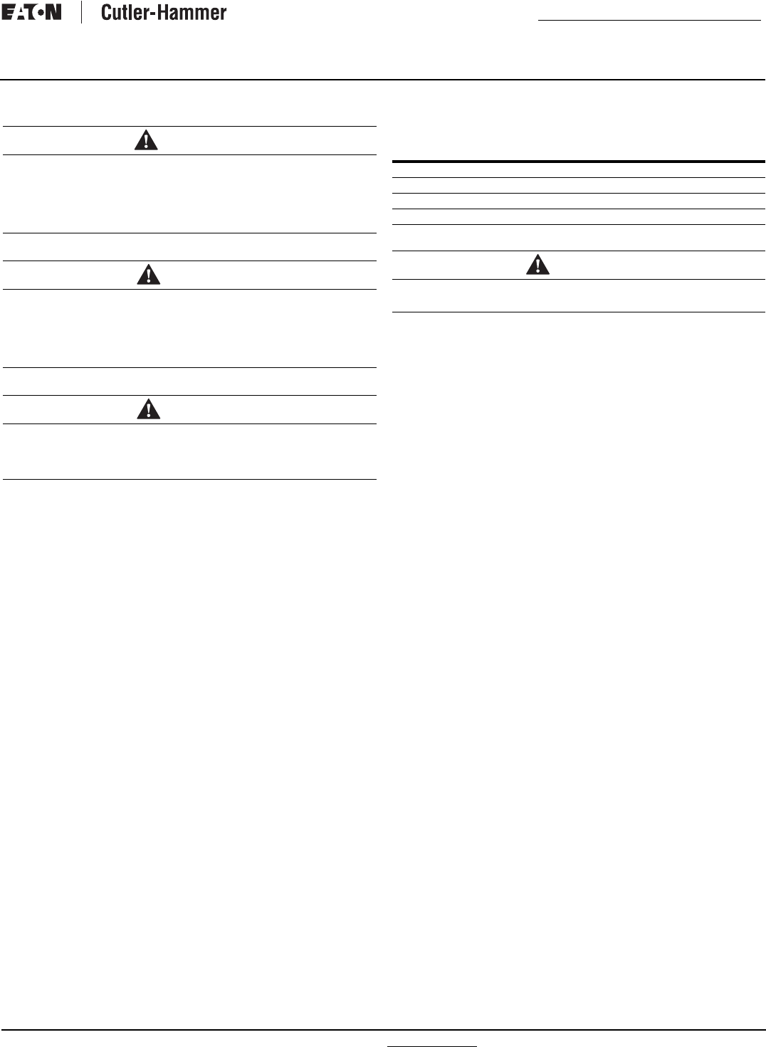
Zone 4 certification is desired (Figure 20), and secure
with 1/2-13 UNC Grade 5 hex bolts.
Step 4: Tighten bolts to 50 ft-lbs (68 Nm).
Step 5: Double check to ensure that all packing and shipping
material has been removed
.
Figure 20. Seismic Tested and Approved Product Mounting Instructions.
CAUTION
SINCE THE ENCLOSED TRANSFER SWITCH MUST BE LIFTED INTO
PLACE FOR MOUNTING, BE CERTAIN THAT ADEQUATE RESOURCES
ARE AVAILABLE FOR LISTING TO AVOID PERSONNEL INJURIES OR
EQUIPMENT DAMAGE.
CAUTION
EXTREME CARE SHOULD BE TAKEN TO PROTECT THE TRANSFER
SWITCH FROM DRILL CHIPS, FILLINGS, AND OTHER CONTAMI-
NANTS WHEN MAKING THE CABLE ENTRY HOLES AND MOUNTING
THE ENCLOSURE TO PREVENT COMPONENT DAMAGE OR A
FUTURE MALFUNCTION.
NOTICE
CABLE ENTRY HOLES ARE NOT PART OF THE ENCLOSURE WHEN
SHIPPED FROM THE FACTORY AND MUST BE PROVIDED IN THE
FIELD, EITHER BEFORE OR AFTER MOUNTING THE ENCLOSURE.
IB01602011E For more information visit: www.Eaton.com
Instructional Booklet
Effective: March 2007 Page 18
Fixed and Drawout Magnum Transfer Switches
4.5 Power Cable Connections
Proceed with the following steps:
Step 1: Verify that the line and load cables comply with applica-
ble electrical codes.
Step 2: Verify that the transfer switch rated current and voltage
(see identification plate on the door of the transfer
switch) agree with system current and voltage.
Step 3: After the transfer switch is mounted, provide the conduit
or cable openings as required. Ensure that no metal filings
contaminate the transfer switch components.
Step 4: Test all power cables before connecting them to the unit
to insure that the conductors or the cable insulation have
not been damaged while being pulled into position.
Step 5: Carefully strip the insulation from the power cables.
Avoid nicking or ringing of the conductor strands. Pre-
pare the stripped conductor termination end by cleaning
it with a wire brush. If aluminum conductors are used,
apply an appropriate joint compound to the clean conduc-
tor surface area. Refer to Figure 13 for the approximate
locations of the power connections.
Power cables are to be connected to solderless screw type lugs
located on the transfer switch switching devices. Refer to the
separate Customer Wiring Diagrams supplied with the transfer
switch equipment for power termination. Verify that the lugs sup-
plied will accommodate the power cables being used. Also verify
that the cables comply with local electrical codes. Standard trans-
fer switch equipment, as supplied from the factory, will accommo-
date the wire sizes shown in Table 5.
Table 5. Wire Size for Available Power Cable
Connections.
Step 6: Tighten the cable lugs to the torque identified on the label
affixed to the door.
Step 7: Make the necessary connections of any options using the
wiring diagrams supplied with the unit.
Step 8: Connect the engine start wires to the logic connector
J5-1 & J5-2 on the ATC-600/ATC-800 Controller.
WARNING
POWER CONDUCTORS MAY HAVE VOLTAGE PRESENT THAT CAN
CAUSE SEVERE PERSONAL INJURY OR DEATH. DE-ENERGIZE ALL
POWER OR CONTROL CIRCUIT CONDUCTORS TO BE CONNECTED
TO THE TRANSFER SWITCH EQUIPMENT BEFORE BEGINNING TO
WORK WITH THE CONDUCTORS AND/OR TERMINATING THEM TO
THE EQUIPMENT.
CAUTION
USE OF CABLE LUGS NOT DESIGNED FOR THE TRANSFER SWITCH
APPLICATIONS MAY CAUSE HEATING PROBLEMS. BREAKER LUGS
ONLY MOUNT TO THE BREAKER, WHILE TRANSFER SWITCH LUGS
MOUNT TO BOTH THE BREAKER AND THE BUS BAR BEHIND THE
BREAKER. FOR INSTALLATION INSTRUCTIONS, REFER TO THE
INSTRUCTION LEAFLET SUPPLIED FOR THE SPECIFIC LUGS.
CAUTION
TO HELP PREVENT COMPONENT DAMAGE OR FUTURE MALFUNC-
TIONS, USE EXTREME CARE TO KEEP CONTAMINANTS OUT OF THE
TRANSFER SWITCH EQUIPMENT WHEN MAKING POWER CABLE
CONNECTIONS.
DEVICE SWITCH
RATING
(AMPS)
CABLES
PER
PHASE
RANGE
WIRING SIZE
Switch 800-2000 6 3/0-750 MCM
Switch 2500-3200 9 3/0-750 MCM
Neutral 800-2000 24 4/0-500 MCM
Neutral 2500-3200 36 4/0-500 MCM
CAUTION
IMPROPER POWER CABLE CONNECTIONS CAN CAUSE EXCESSIVE
HEAT AND SUBSEQUENT EQUIPMENT FAILURE.
IB01602011E For more information visit: www.Eaton.com
Instructional Booklet
Effective: March 2007 Page 19
Fixed and Drawout Magnum Transfer Switches
4.6 Voltage Selection Adjustment
Certain devices, such as the voltage selection panel, sensing
relays, and timers need to be set and/or calibrated prior to placing
the transfer switch equipment into service. Adjustments for logic
devices are described in the separate instructional document dedi-
cated to the specific logic being used. Voltage selection adjust-
ments are described here
Figure 21. Voltage Selection Adjustment.
•Remove the transformer pack cover by loosening the 4 screws
located at each corner of the transformer pack assembly.
•The transformers are factory set on the 600 volt tap. (See illus-
tration above for location of various taps and voltages)
•Detach the spade connector from the 600 volt tap and place on
the tap that is suitable for your application.
.
•After changing the taps on both transformers, replace the trans-
former pack cover and tighten all four screws.
4.7 Mounting the Switching Device in the Drawout
Mechanism
In structures equipped for drawout circuit breakers, a bolted-in
cassette with movable extension rails supports the circuit breaker
(Figure 22). The extension rails must first be pulled all the way
out. Once the rails are fully extended, the circuit breaker can be
carefully placed on the extension rails.
Figure 22. One Side of Drawout Circuit Breaker Properly Seated
on Extension Rails.
PRIMARY
TERMINALS
SECONDARY
TERMINALS
600V 6
480V 5
240V 4
208V 3
120V 2
0V 1
60Hz
7
8
9
10
SECONDARY 1
120V, 300VA
INTERMITTENT 50%
DUTY CYCLE
SECONDARY 2
120V, 25VA
5
10
9
8
7
120V. 1.5A
7810
9
120V 0.21A
TOP: 5-480V 3-208V 1-COMMON
BOTTOM: 6-600V 4-240V 2-120V
31
642
WARNING
DISCONNECT ALL SOURCES OF POWER OR DISCONNECT P7/S7
PRIOR TO PERFORMING THE FOLLOWING. FAILURE TO DO SO MAY
CAUSE SERIOUS INJURY OR DEATH.
CAUTION
BE SURE THAT THE CORRECT VOLTAGE IS SELECTED TO MATCH
THE SYSTEM VOLTAGE. AN IMPROPER SELECTION AND/OR CON-
NECTION COULD RESULT IN EQUIPMENT DAMAGE.
For more information visit: www.Eaton.com IB01602011E
Instructional Booklet
Page 20 Effective: March 2007 Fixed and Drawout Magnum Transfer Switches
Carefully lower the circuit breaker down onto the extension rails.
Be certain that the circuit breaker’s four molded drawout rail sup-
ports are fully seated in the extension rail cutouts on both sides
(Figure 22). Do not remove the lifting yoke from the circuit
breaker until it is properly seated on the rails.
Once the circuit breaker is on the extension rails and the lifting
yoke is removed, proceed with the rest of the circuit breaker
installation.
4.8 Wiring
Power sources, load conductors, and control wiring should be
connected to locations as indicated in the Customer Wiring Dia-
grams supplied with the transfer switch equipment.
4.8.1 Engine Start Connection
The engine control contact connections are located on the
ATC-600/ATC 800 Controller. The engine control contact con-
nections of bypass isolation units are located in the door of the
enclosure
Note: Prior to making the engine start connection to the switch on bypass
isolation units, set the engine generator controls selector switch in the OFF
position to prevent an unwanted engine start. A contact closes between
these terminal blocks when an engine start signal is provided by the ATS
logic.
4.8.2 ALARM CONTACTS (CLOSED TRANSITION ONLY)
Closed transition only ATSs are provided with an extra shunt trip
on the Source 1 device. This shunt trip is energized when the
Time Delay Utility Parallel (TDUP) times out (preset by user), thus
opening the source device. The TDUP timer starts timing when
both sources are paralleled. Refer to the IQ Transfer instruction
book for additional alarms.
Section 5: Operation
5.1 General
A transfer switch provides main contacts to connect and discon-
nect the load to and from the Source 1 and Source 2 power
sources. A stored-energy type transfer mechanism provides the
mechanical motion required to open and close the main contacts
(Paragraph 3.2.1).
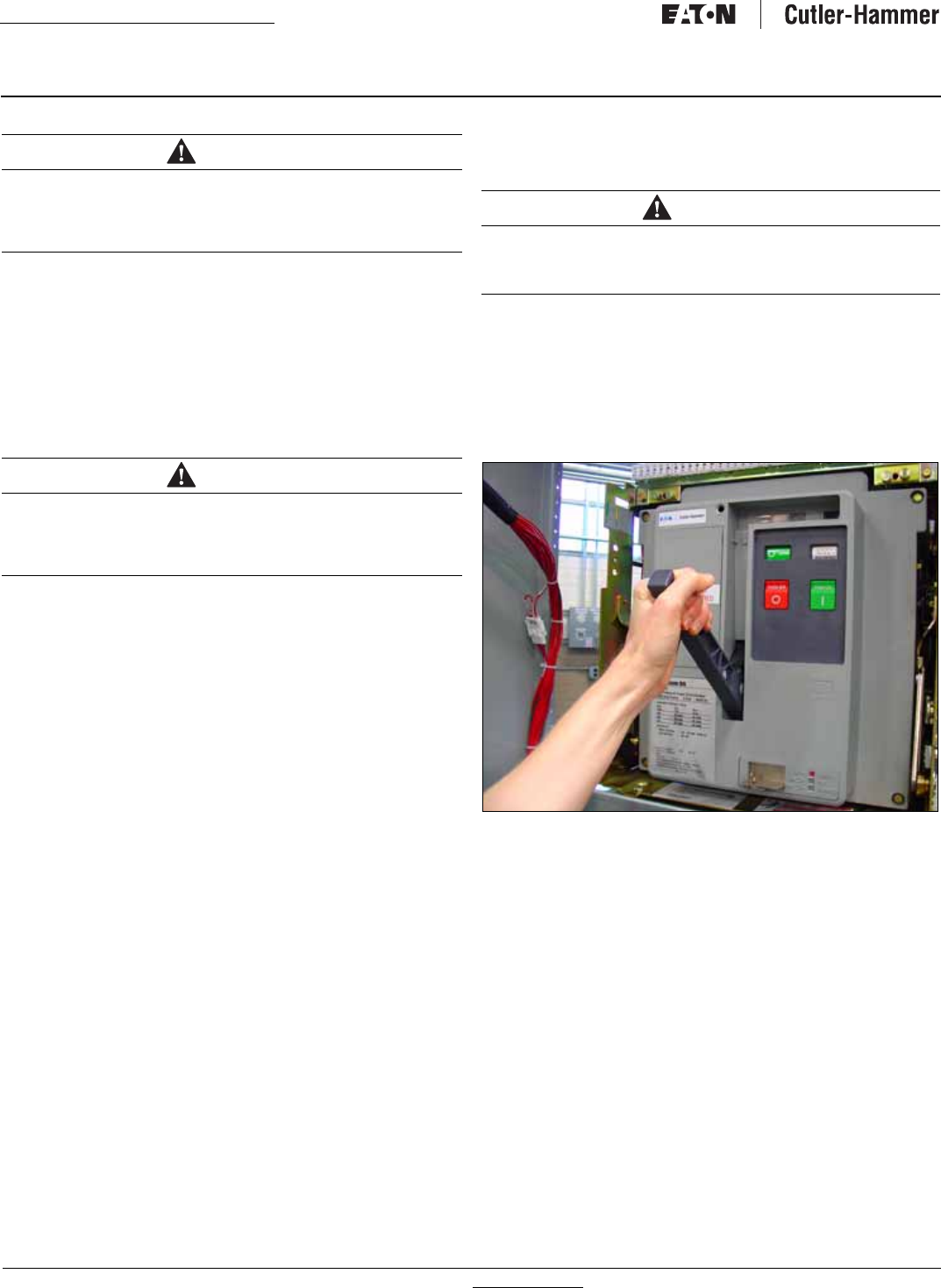
Each switch can be manually operated. Before a switching device
can be closed, the stored energy mechanism must be charged by
pumping the handle (Figure 23).
Figure 23. Pumping Handle Charges Stored Energy Mechanism
(Closed Transition Shown).
In the closed transition product, a single switching device can be
manually closed by following the instructions detailed in Figure
25. An indicator window shows whether the switch is open or
closed.
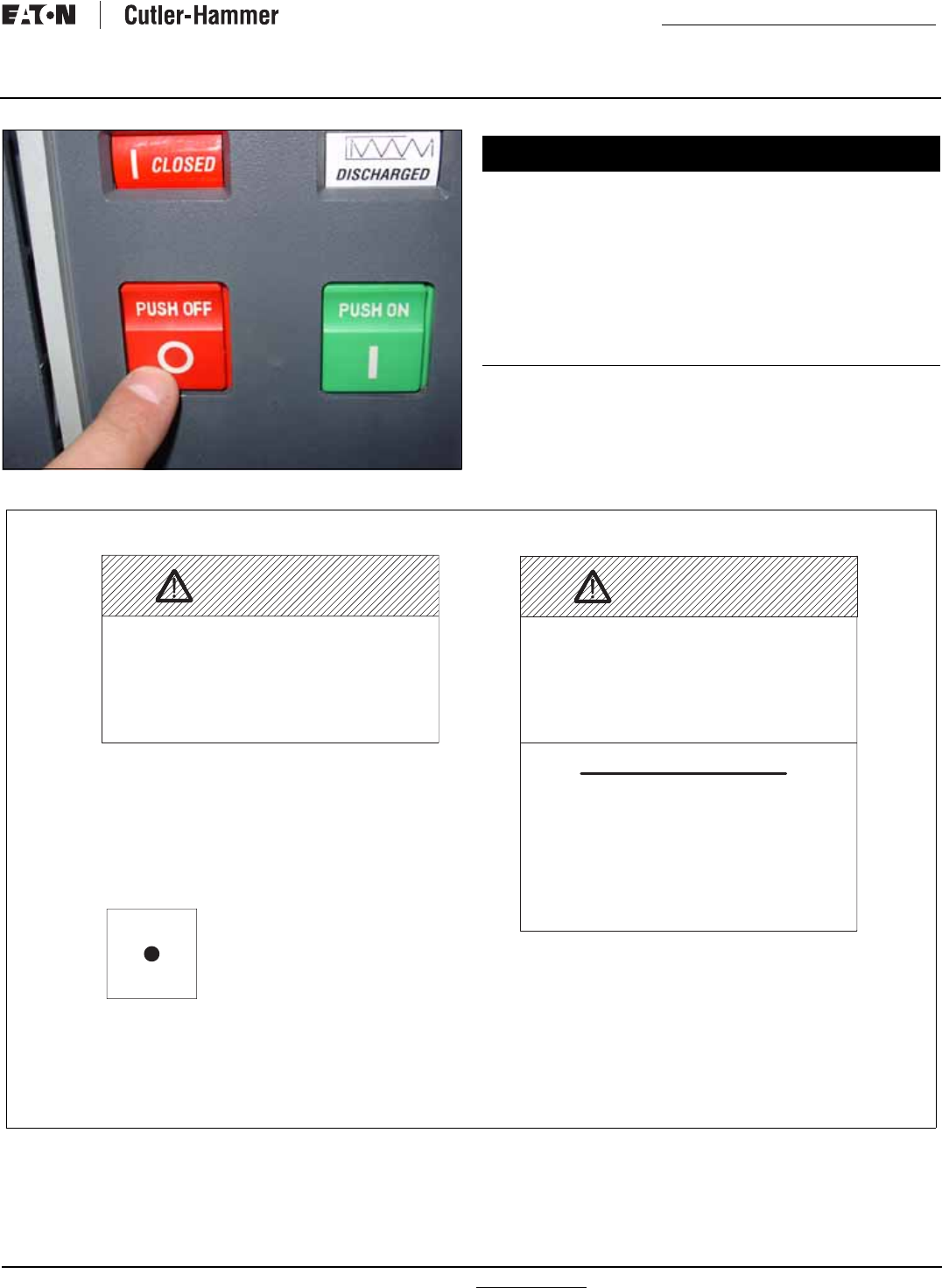
The open transition switching device can be closed by pushing the
close button (Figure 24). The other switching device is prevented
from closing through a rigid mechanical interlock (Paragraph
3.2.2). An indicator window shows whether the switch is open
or closed.
CAUTION
IT IS IMPORTANT TO TAKE GREAT CARE WHEN PLACING A DRA-
WOUT CIRCUIT BREAKER ON ITS EXTENSION RAILS. IF THE CIR-
CUIT BREAKER IS NOT PROPERLY SEATED ON THE EXTENSION
RAILS, IT COULD FALL FROM THE RAILS CAUSING EQUIPMENT
DAMAGE AND/OR BODILY INJURY.
CAUTION
POWER CONDUCTORS AND CONTROL WIRING MAY HAVE VOLT-
AGE PRESENT THAT CAN CAUSE SEVERE PERSONAL INJURY OR
DEATH. DE-ENERGIZE ALL POWER OR CONTROL CIRCUIT CONDUC-
TORS BEFORE BEGINNING TO PERFORM ANY WIRING ACTIVITY TO
OR WITHIN THE TRANSFER SWITCH EQUIPMENT.
WARNING
THE CLOSED TRANSITION PRODUCT CONTAINS A SPECIAL CON-
TACT ARRANGEMENT (OVERLAPPING CONTACTS). MISUSE CAN
RESULT IN DEATH, SEVERE PERSONAL INJURY, AND/OR PROPERTY
DAMAGE.
IB01602011E For more information visit: www.Eaton.com
Instructional Booklet
Effective: March 2007 Page 21
Fixed and Drawout Magnum Transfer Switches
Figure 24. Close Switch by Pushing Close Button.
5.2 Automatic Transfer Switch
The operating sequence of an ATS is dictated by the switch’s
standard features and selected options. Operation of an ATS dur-
ing Source 1 power source failure, Source 1 power source restora-
tion, and testing is described in the associated Controller
Instruction Booklet.
Figure 25. Switching Device Closing Precautions (Closed Transition Only).
NOTICE
IF A TRANSFER SWITCH WITH ANY TYPE OF ELECTRICAL OPERAT-
ING CAPABILITIES IS TO BE OPERATED MANUALLY UTILIZING THE
MANUAL OPERATING HANDLE, IT IS STRONGLY RECOMMENDED
THAT THE TRANSFER CONTROL CIRCUIT FIRST BE ISOLATED. THIS
IS ACCOMPLISHED BY DISCONNECTING THE S7/P7 PLUG ON THE
TRANSFORMER PANEL. AN AUTOMATIC ENGINE START WILL
OCCUR UNLESS THE GENERATOR RUN SWITCH SET TO “OFF.” IF,
HOWEVER, A TRANSFER SWITCH IS SUPPLIED WITH A FOUR-POSI-
TION SELECTOR SWITCH (OPTION 6H), IT CAN BE TURNED TO THE
OFF POSITION, MAKING IT UNNECESSARY TO UNPLUG THE LOGIC.
IN THE CASE OF THE ATS DESIGN, ANY ATTEMPT TO OPERATE
THE MANUAL HANDLE WITHOUT FIRST ISOLATING THE CONTROL
CIRCUIT CAUSES AN AUTOMATIC TRANSFER.
Follow Manual Operation Instructions Below
switching devices simultaneously
can cause severe injury
Attempting to close both
or death.
WARNING
2. Open both switching devices
Manual Operation Instructions
4. Verify source availability
5. Close switching device on available
source
1. Disconnect Logic Connectors
3. Verify "OPEN" flags
7805C60H05
MANUAL CLOSE BUTTON
Operating Instructions
Do Not Use Without
Reading Manual
OVERLAPPING CONTACTS
must be Synchronized
SOURCE 1 AND SOURCE 2
WARNING
7805C60H04
THIS PRODUCT CONTAINS A SPECIAL CON-
TACT ARRANGEMENT (OVERLAPPING CON-
TACTS). MISUSE CAN RESULT IN DEATH
SEVERE PERSONAL INJURY OR PROPERTY
DAMAGE.
(THIS LABEL IS APPLIED TO THE DOOR )
FOLLOW THE INSTRUCTIONS
OUTLINED IN THE NEXT
WARNING LABEL.
(THIS LABEL IS APPLIED TO
THE COVER OF THE MANUAL
CLOSE BUTTON ON EACH
THESE INSTRUCTIONS ONLY PERTAIN TO
MANUALLY CLOSING A SINGLE SWITCHING
DEVICE. ATTEMPTING TO CLOSE BOTH
SWITCHING DEVICES CAN CAUSE SEVERE
INJURY OR DEATH.
THIS LABEL IS APPLIED TO THE DOOR.
For more information visit: www.Eaton.com IB01602011E
Instructional Booklet
Page 22 Effective: March 2007 Fixed and Drawout Magnum Transfer Switches
Section 6: Drawout and Fixed Switching
Devices
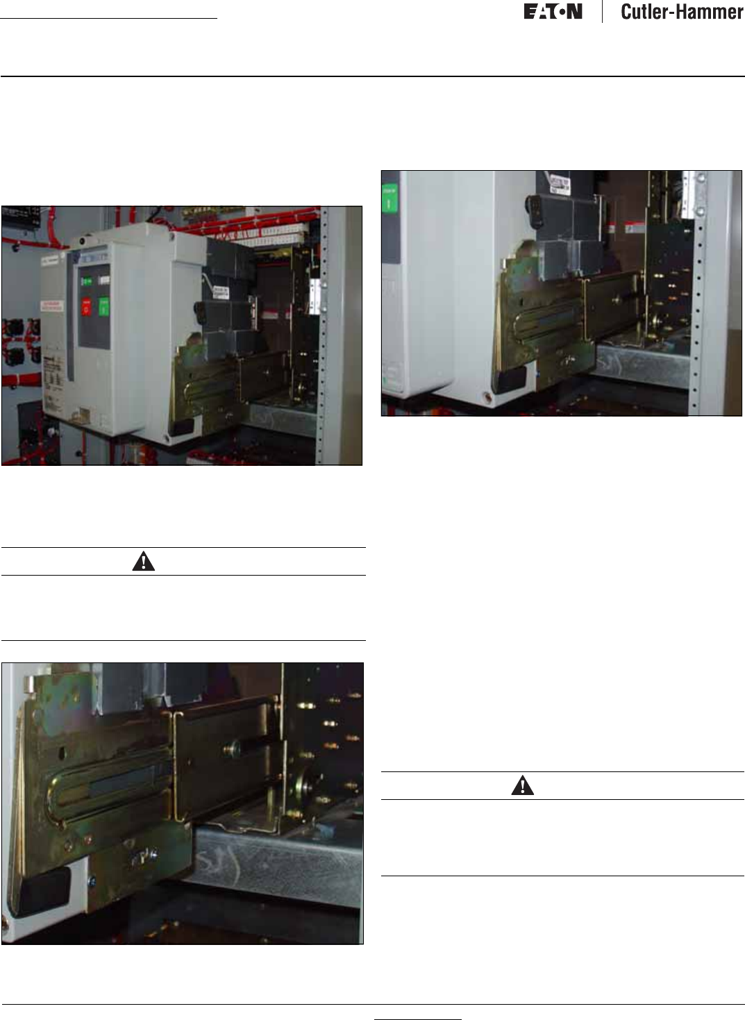
6.1 Installing a Drawout Switching Device
In transfer switches equipped with drawout switching devices,
bolted-in carriages with extendable rails support the switching
devices.
Figure 26. Switching Device Drawn Out from the Transfer Switch.
To install a drawout switching device, the extendable rails must
first be pulled all the way out. Once the rails are fully extended,
the switching device can be carefully placed on the rails.
Figure 27. Drawout Rail Supports Fully Seated in the Rail
Cutouts.
Carefully lower the switching device onto the extended rails. Be
certain that the switching device’s four molded drawout rail sup-
ports are fully seated in the extendable rail cutouts on both sides
(Figure28). Do not remove the lifting yoke from the switching
device until it is properly seated on the rails.
Figure 28. Switching Device in the REMOVE Position.
Once the switching device is properly seated on the extended
rails, the lifting yoke can be removed and the rest of the switching
device installation procedure can be completed.
6.1.1 Switching Device Positioning
The Magnum drawout switching device has four normal positions:
•REMOVE (Withdrawn) (Figure 28)
•DISCONNECT (Figure 31)
•TEST (Figure 30)
•CONNECT (Figure 29)
The REMOVE position is a position outside the compartment on
the carriages drawout rails where the switching device is not
engaged with the levering mechanism. The DISCONNECT, TEST,
and CONNECT, positions are reached by means of the levering
mechanism.
With the switching device solidly positioned on the carriage’s
extendable rails and the levering-in mechanism in the
DISCONNECT position, carefully and firmly push the switching
device into the compartment as far as it will go. The outer
(recessed) portion of the switching device face plate should align
with the GREEN target line (labeled DISC) on the inside top left
wall of the carriage (Figure 32).
CAUTION
IT IS IMPORTANT TO TAKE GREAT CARE WHEN PLACING A DRA-
WOUT SWITCHING DEVICE ON ITS EXTENDED RAILS. IF THE
SWITCHING DEVICE IS NOT PROPERLY SEATED ON THE EXTEND-
ABLE RAILS, IT COULD FALL FROM THE RAILS CAUSING EQUIP-
MENT DAMAGE AND/OR BODILY INJURY.
CAUTION
MAKE CERTAIN THAT THE SWITCHING DEVICE IS FULLY INSERTED
INTO ITS COMPARTMENT BEFORE ANY ATTEMPT IS MADE TO
LEVER THE SWITCHING DEVICE. ATTEMPTING TO LEVER THE
SWITCHING DEVICE IN BEFORE IT IS FULLY POSITIONED INSIDE ITS
COMPARTMENT CAN RESULT IN DAMAGE TO BOTH THE SWITCH-
ING DEVICE AND THE COMPARTMENT.
IB01602011E For more information visit: www.Eaton.com
Instructional Booklet
Effective: March 2007 Page 23
Fixed and Drawout Magnum Transfer Switches
Figure 29. Switching Device in the CONNECT Position.
Figure 30. Switching Device in the TEST Position.
Figure 31. Switching Device in the DISCONNECT Position.
For more information visit: www.Eaton.com IB01602011E
Instructional Booklet
Page 24 Effective: March 2007 Fixed and Drawout Magnum Transfer Switches
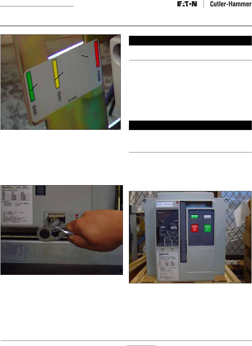
Figure 32.Carriage Label Showing DISCONNECT, TEST, and
CONNECT Positions of the Recessed Cover.
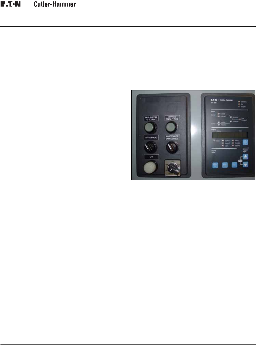
6.1.2 Levering the Switching Device
The switching device is now ready to be levered. With the
switching device OPEN, the levering device access door can be
raised. The levering device is hand operated using a standard
3/8” square drive and ratchet, which is not provided (Figure 33).
As long as the access door is raised, the switching device is held
in the “trip free” condition. Begin by rotating the levering-in screw
to the full counter clockwise (DISCONNECT) position.
Figure 33.Levering and Position Indication.
Close the compartment door and begin levering the switching
device into its different positions using a clockwise ratcheting
motion. When the switching device is levered fully to the
DISCONNECT or CONNECT position, the levering shaft hits a hard
stop. Do NOT exceed 25 ft lb (33.9 Nm) of torque or the levering
mechanism may be damaged.
The position of the switching device within its compartment is
indicated by color coded position indicators (See
Figure 29 through 32):
•Red=Connect;
•Yellow=Test; and
•Green=Disconnect.
To remove the switching device from its compartment, follow the
procedure just described using a counter clockwise ratcheting
motion.
6.2. Fixed Switching Device
The Magnum fixed type switching device differs from the drawout
version in that it has no levering device, primary disconnects, and
secondary disconnects (Figure 34). In addition, a fixed switching
device does not have a standard feature to hold the switching
device in a “trip free” position
Figure 34. Typical Magnum Fixed Switching Device.
Fixed switching device terminals have holes for making bolted hor-
izontal primary bus connections. Adapters are available for mak-
ing vertical primary bus connections. Secondary connections can
be made through standard terminal blocks or a special connector
compatible with the drawout switching device’s type secondary
connector. Both secondary connection devices are mounted at
the top front of the switching device.
Red
Yellow
Green
NOTICE
THE SWITCHING DEVICE CAN BE LEVERED WITH THE COMPART-
MENT DOOR OPEN OR CLOSED, BUT IT IS ADVISABLE TO CLOSE
THE DOOR PRIOR TO LEVERING.
NOTICE
THE SWITCHING DEVICE MECHANISM IS INTERLOCKED SUCH
THAT CHARGED CLOSING SPRINGS ARE AUTOMATICALLY DIS-
CHARGED IF THE SWITCHING DEVICE IS LEVERED INTO OR OUT OF
THE CELL. DISCHARGE TAKES PLACE BETWEEN THE DISCONNECT
AND TEST POSITION.
IB01602011E For more information visit: www.Eaton.com
Instructional Booklet
Effective: March 2007 Page 25
Fixed and Drawout Magnum Transfer Switches
The fixed switching device frame has two mounting feet, one on
each side, to permit the fixed switching device to be securely
mounted. Each mounting foot has two slotted mounting holes
which are used to bolt the switching device securely in place. Use
either 3/8” or M 10 bolts for this purpose. Refer to the dimen-
sional drawings supplied with the transfer switch for switching
device and bus stab dimensions.
6.3 Switching Device Operation
Switching devices should be operated manually and/or electrically
before they are put into service. This can be done during the
installation process or some later date prior to start-up. To check
the switching device operation, follow the operational procedures
outlined in switching device manual supplied with the transfer
switch for both manually operated and electrically operated
switching devices.
Section 7: Operation of the Bypass Isolation
Transfer Switch
7.1 Operator Panel
The design of this transfer switch allows quick removal of the dif-
ferent switching devices for inspection or maintenance or, if
required, quick replacement.
The bypass isolation switch has two operator panels with
switches and lights (Figure 35). The following descriptions are for
those features that are standard with the bypass isolation switch.
Additional features are described in the options section.
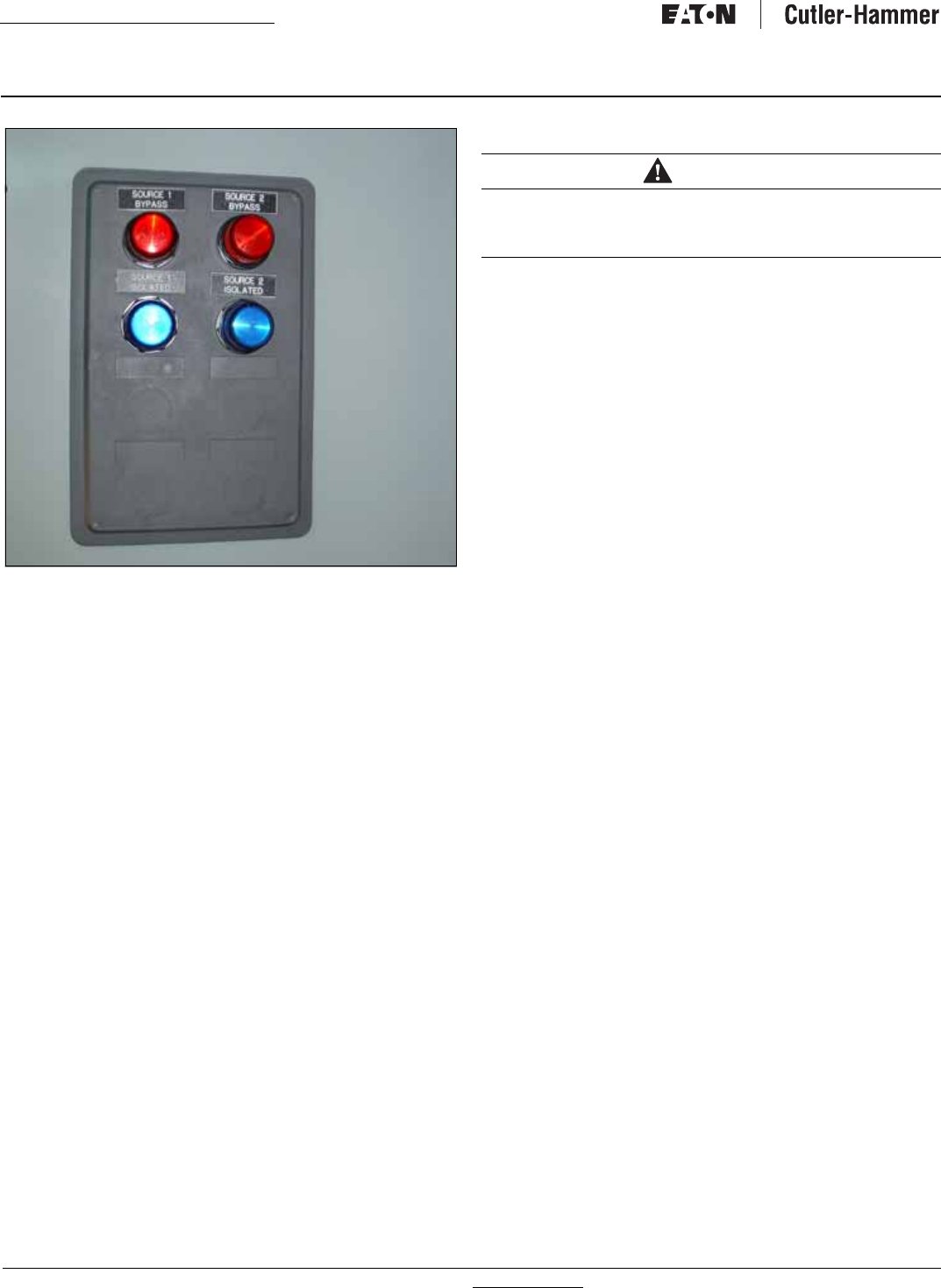
Figure 35.Bypass Isolation Switch.
The left door control panel has the following standard features:
1. Light to indicate if the Source 1 power source is available.
2. Light to indicate if the Source 2 power source is available.
3. Light to indicate if the Source 1position is energized, that is,
the Source 1 switching device in the automatic transfer
switch is closed.
4. Light to indicate if the Source 2 position is energized, that is,
the Source 2 switching device in the automatic transfer
switch is closed.
5. The Push-To-Test button allows testing of the transfer
switch. Pushing the button two times will simulate a power
failure, causing the transfer switch to start the transfer
sequence. Pressing the button again will restore regular
power.
Three-position selector switch to control the generator:
•AUTO - The intelligence circuit of the transfer switch will start
the generator if the Source 1 power source is not available.
•OFF - The intelligence circuit of the transfer switch will not be
able to start the generator, which eliminates nuisance starts
during maintenance.
•RUN - The generator will run regardless of the availability of the
Source 1 power source.
For more information visit: www.Eaton.com IB01602011E
Instructional Booklet
Page 26 Effective: March 2007 Fixed and Drawout Magnum Transfer Switches
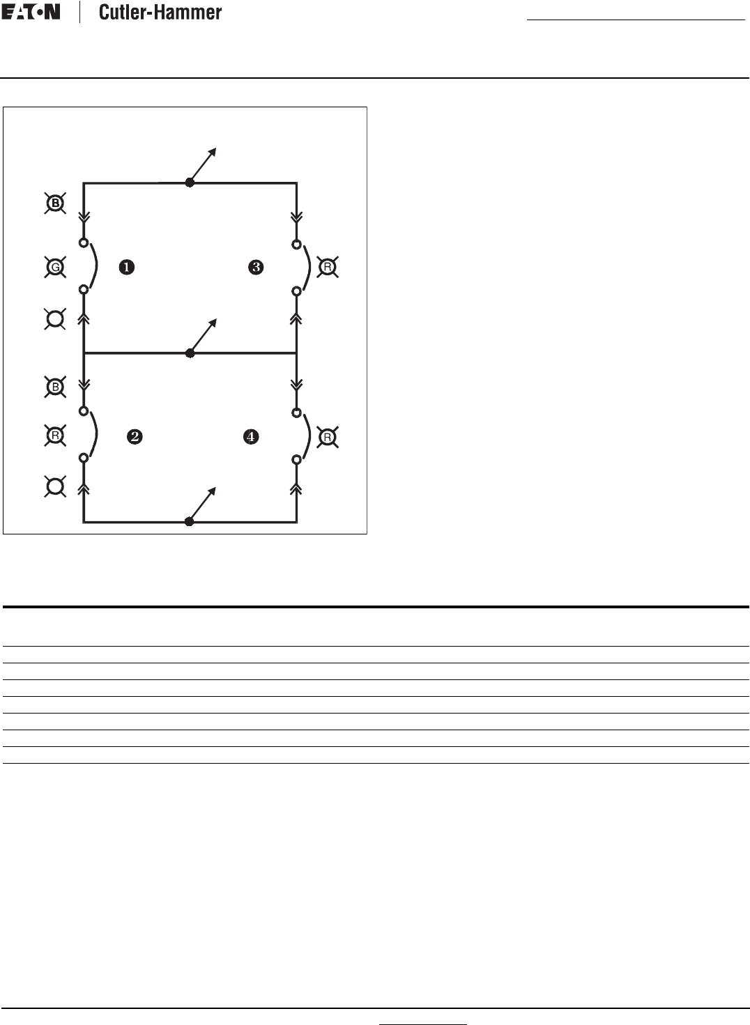
Figure 36. Magnum Bypass Lights.
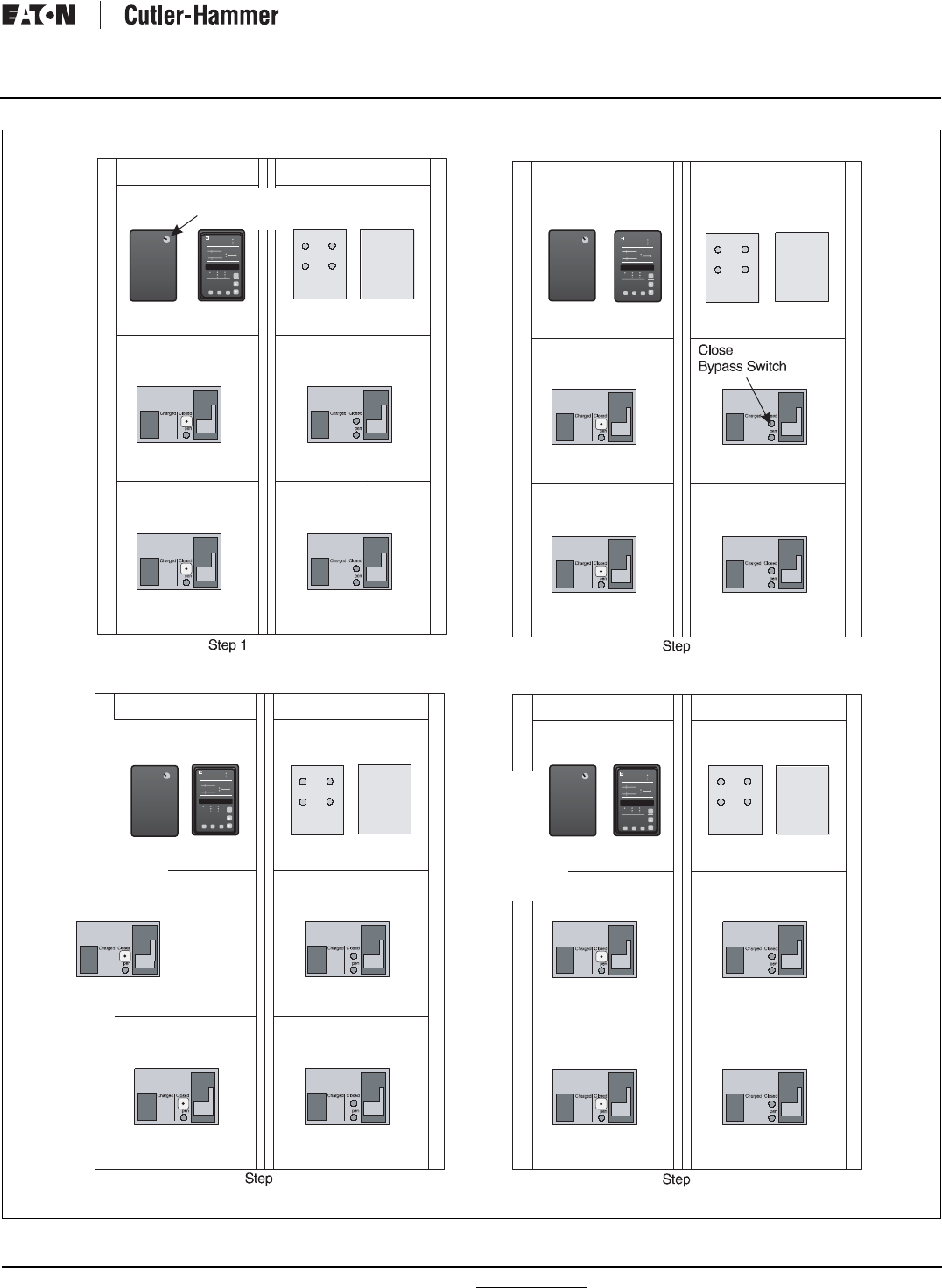
The right door control panel has the following standard features:
1. Light to indicate if the Source 1 switching device is isolated
(only if the Source 1 switching device is racked out).
2. Light to indicate if the Source 2 switching device is isolated
(only if the Source 2 switching device is racked out).
3. Light to indicate if the Source 1 bypass switching device is
closed.
4. Light to indicate if the Source 2 bypass switching device is
closed.
7.2 Automatic Operation
The intelligence/supervisory circuits on Eaton transfer switches
constantly monitor the condition of both the Source 1 and Source
2 power sources. These circuits automatically initiate an immedi-
ate transfer of power from the Source 1 to the Source 2 power
source when the power source fails or the voltage level drops
below a preset value. Transfer back to the Source 1 power
source is automatic upon return of the Source 1 power source.
Monitoring the power source is always performed on the line side
of the power source to which the switch is connected. The
Source 1 power source is the preferred source and the transfer
switch will always seek this source when it is available.
7.3 Bypassing the Transfer Switch
7.3.1 Source 1 to Source 1 BYPASS
The Source 1 switching device can be bypassed and isolated by
the following sequence (Figures 36 and 37):
1. Move the generator selector switch to the OFF position to
avoid nuisance starts.
2. Close the Source 1 bypass switch manually. The Source 1
bypassed light will illuminate.
3. Open and rack out the Source 1 switching device (see Section
6). The Source 1 isolated light will illuminate and the Source 1
position energized light will no longer be illuminated.
4. Inspect and/or perform the needed maintenance on the Source
1 switching device.
5. Rack in the Source 1 switching device (see Section 6). The
Source 1 switching device will automatically recharge and
close when it is in the CONNECT position. The Source 1 iso-
lated light will no longer be illuminated, but the Source 1 posi-
tion energized light will be illuminated.
6. Open the Source 1 bypass switch. The Source 1 bypassed
light will no longer be illuminated.
7. The Source 1 switching device is now back in automatic oper-
ation.
7.3.2 Source 2 TO Source 2 BYPASS
The Source 2 switching device can be bypassed and isolated by
the following sequence:
1. Move the generator selector switch to the RUN position to
avoid losing power.
2. Close the Source 2 bypass switching device manually. The
Source 2 bypass light will illuminate.
3. Open and rack out the Source 2 switching device
(see Section 6). The Source 2 isolated light will illuminate and
the Source 2 position energized light will no longer be illumi-
nated.
4. Inspect and/or perform the needed maintenance on the Source
2 switching device.
5. Rack in the Source 2 switching device (see Section 6). The
Source 2 switching device will automatically recharge and
close when in the CONNECT position. The Source 2 isolated
light will no longer be illuminated, and the Source 2 position
energized light will illuminate.
6. Open the Source 2 Bypass switch. The source 2 Bypass light
will no longer be illuminated.
7. The Source 2 Switch is now back in automatic operation.
WARNING
THE CLOSED TRANSITION PRODUCT CONTAINS A SPECIAL CON-
TACT ARRANGEMENT (OVERLAPPING CONTACTS). MISUSE CAN
RESULT IN DEATH, SEVERE PERSONAL INJURY, AND/OR PROPERTY
DAMAGE.
IB01602011E For more information visit: www.Eaton.com
Instructional Booklet
Effective: March 2007 Page 27
Fixed and Drawout Magnum Transfer Switches
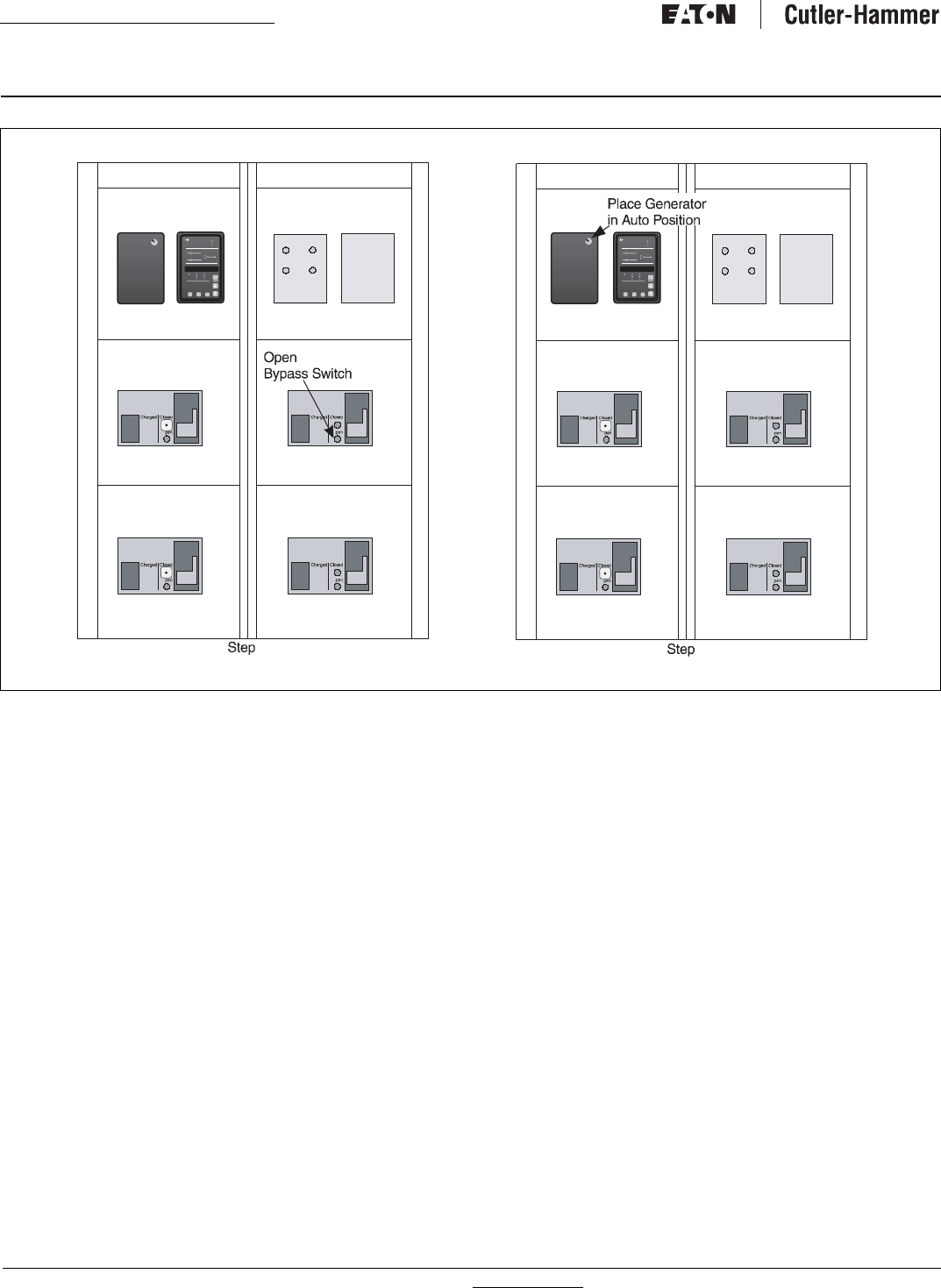
Figure 37. Transfer from Normal Switching Device to Normal Bypass Switching Device, Steps 1-4.
Rack Out and
Inspect/Maintain
Switch
Place Generator
In OFF Position
Cutler-Hammer
Digitrip 3000 Operational
High Load
Communications
Trip
Time Overcurrent
Curve Shape
Pickup (x In)
Time Multiplier
Pickup (x In)
Time
Program
Phase
Ground
I
I
I
RMS Amperes
Settings/Test Time/Trip Cause
Test
Program
Test
Pickup (x In)
Instantaneous
Short Delay
Amp Demand
I
Cutler-Hammer
Phase
Phase Phase
Phase
Ground
Digitrip 3000 Operatio
High
Commun
Time Overcurrent
Curve Shape
Pickup (x In)
Time Multiplier
Time
Program
Phase
Ground
RMS
Settings/Test
Time/Trip Cause
Short Delay
Cutler-Hammer
Digitrip 3000 Operational
High Load
Communications
Trip
Time Overcurrent
Curve Shape
Pickup (x In)
Time Multiplier
Pickup (x In)
Time
Program
Phase
Ground
I
I
I
RMS Amperes
Settings/Test Time/Trip Cause
Test
Program
Test
Pickup (x In)
Instantaneous
Short Delay
Amp Demand
I
Cutler-Hammer
Phase
Phase Phase
Phase
Ground
Digitrip 3000 Operatio
High
Commun
Time Overcurrent
Curve Shape
Pickup (x In)
Time Multiplier
Time
Program
Phase
Ground
RMS
Settings/Test
Time/Trip Cause
Short Delay
2
Source 1
3
Rack Source 1
Switch Back
into Its
Location
Switch Will
Automatically
close
Cutler-Hammer
Digitrip 3000 Operational
High Load
Communications
Trip
Time Overcurrent
Curve Shape
Pickup (x In)
Time Multiplier
Pickup (x In)
Time
Program
Phase
Ground
I
I
I
RMS Amperes
Settings/Test Time/Trip Cause
Test
Program
Test
Pickup (x In)
Instantaneous
Short Delay
Amp Demand
I
Cutler-Hammer
Phase
Phase Phase
Phase
Ground
Digitrip 3000 Operatio
High
Commun
Time Overcurrent
Curve Shape
Pickup (x In)
Time Multiplier
Time
Program
Phase
Ground
RMS
Settings/Test
Time/Trip Cause
Short Delay
4
For more information visit: www.Eaton.com IB01602011E
Instructional Booklet
Page 28 Effective: March 2007 Fixed and Drawout Magnum Transfer Switches
Figure 38. Transfer from Normal Switching Device to Normal Bypass Switching Device, Steps 5-6.
7.3.3 Source 1 to Source 2 Bypass (Open Transition Only)
The Source 1 switch can be isolated and bypassed by the follow-
ing sequence:
1. Move the generator selector switch to the RUN position
because the load needs to be energized from the Source 2
power source.
2. Make sure that the Source 2 power source is available.
3. Open the source/switching device.
4. Close the Source 2 bypass switching device manually. The
Source 2 bypass light will be illuminated.
5. Rack out the Source 1 switching device (see Section 6). The
Source 1 isolated light will illuminate.
6. Inspect and/or perform the needed maintenance on the
Source 1 switching device.
7. Rack in the Source 1 switching device (see Section 6). The
Source 1 switching device will automatically recharge when it
is in the CONNECT position. The Source 1 isolated light will
no longer be illuminated.
8. Open the Source 2 bypass switching device. The Source 2
bypass light will no longer be illuminated.
9. The Source 1 switching device is now back in automatic oper-
ation.
7.3.4 Source 2 to Source 1 Bypass (Open Transition Only)
The Source 2 switching device can be bypassed and isolated by
the following sequence:
1. Ensure that the Source 1 power is available since the load will
be energized from the Source 1 power source.
2. Move the generator selector switch to the OFF position to
avoid nuisance starting of the generator while work is being
performed on the Source 2 switching device.
3. Open the Source 2 switching device.
4. Close the Source 1 bypass switching device manually. The
Source 1 bypass light will illuminate.
5. Rack out the Source 2 switching device (see Section 6). The
Source 2 isolated light will illuminate.
6. Inspect and/or perform the needed maintenance on the
Source 2 switching device.
7. Rack in the Source 2 switching device (see Section 6). The
Source 2 isolated light will no longer be illuminated.
8. Open the Source 1 bypass switching device. The
Source 1 light will no longer be illuminated.
9. The switching device is now back in automatic operation.
Cutler-Hammer
Digitrip 3000 Operational
High Load
Communications
Trip
Time Overcurrent
Curve Shape
Pickup (x In)
Time Multiplier
Pickup (x In)
Time
Program
Phase
Ground
I
I
I
RMS Amperes
Settings/Test Time/Trip Cause
Test
Program
Test
Pickup (x In)
Instantaneous
Short Delay
Amp Demand
I
Cutler-Hammer
Phase
Phase Phase
Phase
Ground
Digitrip 3000 Operatio
High
Commun
Time Overcurrent
Curve Shape
Pickup (x In)
Time Multiplier
Time
Program
Phase
Ground
RMS
Settings/Test
Time/Trip Cause
Short Delay
Cutler-Hammer
Digitrip 3000 Operational
High Load
Communications
Trip
Time Overcurrent
Curve Shape
Pickup (x In)
Time Multiplier
Pickup (x In)
Time
Program
Phase
Ground
I
I
I
RMS Amperes
Settings/Test Time/Trip Cause
Test
Program
Test
Pickup (x In)
Instantaneous
Short Delay
Amp Demand
I
Cutler-Hammer
Phase
Phase Phase
Phase
Ground
Digitrip 3000 Operatio
High
Commun
Time Overcurrent
Curve Shape
Pickup (x In)
Time Multiplier
Time
Program
Phase
Ground
RMS
Settings/Test
Time/Trip Cause
Short Delay
5
Source 1
6
IB01602011E For more information visit: www.Eaton.com
Instructional Booklet
Effective: March 2007 Page 29
Fixed and Drawout Magnum Transfer Switches
7.4 Manual Operation When in Bypass Mode
7.4.1 Source 1 Bypass to Source 2 Bypass
When the transfer switch is set to Source 1 bypass, it can be
transferred to Source 2 bypass by the following sequence:
1. Move the generator selector switch to the RUN position.
2. Open the Source 1 bypass switching device. The Source 1
bypass light will no longer be illuminated.
3. Close the Source 2 bypass switching device manually and the
Source 2 bypass light will illuminate.
7.4.2 Source 2 Bypass to Source 1 Bypass
When the transfer switch is set to Source 2 bypass, it can be
transferred to the Source 1 bypass switching device by the follow-
ing sequence:
1. Open the Source 2 bypass switching device and the Source 2
bypass light will no longer be illuminated.
2. Close the Source 1 bypass switching device manually and the
Source 1 bypass light will illuminate.
3. Move the generator selector switch to the OFF position.
Section 8: Testing and Problem Solving
8.1 Testing
After transfer switch equipment is initially installed or during
planned outages, the installation should be tested to ensure that all
equipment operates properly. This attention to detail will help to
avoid unexpected malfunctions. Mechanical and/or electrical tests
should be performed.
The frequency of subsequent testing should be based on recom-
mendations of the generator set manufacturer. Use the test push-
button to check the electrical operation of the switch. IF A TEST
SWITCH IS PROVIDED, ALWAYS RETURN THE SWITCH TO THE
AUTO POSITION AFTER THE TEST IS COMPLETE.
8.2 Problem Solving
A basic problem solving effort is the first step to take prior to call-
ing for assistance. Frequently, the effort will successfully address
most problems encountered. Most problem solving procedures
are outlined in the instruction manual unique to the type of logic
being used. In addition, several problem solving procedures are
presented here which are specific to the type of switches or
switching devices used in this equipment.
WARNING
HIGH VOLTAGES ASSOCIATED WITH OPERATIONAL TRANSFER
SWITCH EQUIPMENT PRESENT A SHOCK HAZARD THAT CAN
CAUSE SEVERE PERSONAL INJURY OR DEATH. USE EXTREME
CAUTION TO AVOID TOUCHING ELECTRICAL CONNECTIONS
WHENEVER INSPECTING OR TESTING THE EQUIPMENT.
IN ADDITION, IMPROPER OPERATION OF THE GENERATOR SET PRE-
SENTS A HAZARD THAT CAN CAUSE SEVERE PERSONAL INJURY
OR DEATH. OBSERVE ALL SAFETY PRECAUTIONS IN YOUR GENER-
ATOR SET OPERATIONS AND INSTALLATION MANUALS
WARNING
FOR MECHANICAL OPERATIONS, REFER TO SECTION 5. IN THIS
INSTRUCTION BOOK. REFER TO THE APPLICABLE LOGIC INSTRUC-
TION BOOK FOR ELECTRICAL TESTING
WARNING
HAZARDOUS VOLTAGES IN AND AROUND TRANSFER SWITCH
EQUIPMENT DURING THE PROBLEM SOLVING PROCESS CAN
CAUSE PERSONAL INJURY AND/OR DEATH. AVOID CONTACT
WITH ANY VOLTAGE SOURCE WHILE PROBLEM SOLVING.
WARNING
ONLY PROPERLY TRAINED PERSONNEL FAMILIAR WITH THE
TRANSFER SWITCH EQUIPMENT AND ITS ASSOCIATED EQUIP-
MENT SHOULD BE PERMITTED TO PERFORM THE PROBLEM SOLV-
ING FUNCTION. IF AN INDIVIDUAL DOES NOT FEEL QUALIFIED TO
PERFORM THE PROBLEM SOLVING FUNCTION, THE INDIVIDUAL
SHOULD NOT ATTEMPT TO PERFORM ANY OF THESE PROCE-
DURES.
For more information visit: www.Eaton.com IB01602011E
Instructional Booklet
Page 30 Effective: March 2007 Fixed and Drawout Magnum Transfer Switches
If a problem persists after having completed the problem solving
procedure, contact an Eaton representative for further assistance.
When calling for assistance, the following is the MINIMUM infor-
mation required to properly address the need:
1. Shop Order Number (SO #) or General Order Number
(GO #) of the transfer switch, plus related Item Number;
2. Catalog and/or Style Number of the transfer switch;
3. Actual location of transfer switch (type of facility, address,
etc.);
4. Company name;
5. Name and position of individual representing company;
6. Basic description of situation as it exists; and
7. Any results of problem solving steps taken and/or readings
taken.
8.2.1 Transfer Switch Appears Inoperative
Step 1: Verify that all plugs and sockets are properly intercon-
nected.
Step 2: Verify that the correct system voltage appears at
Source 1 switch. Measure the voltage at the breaker
lugs.
Step 3: Verify that the voltage selection plug is in the proper posi-
tion to match the system voltage.
Step 4: Look for any obviously burned components. Determine
the cause and rectify, if possible. Replace any defective
components after the cause is determined.
Step 5: For closed transition, refer to Figure 25 for manual oper-
ating instructions. Verify whether or not the system volt-
age now appears on the load terminals.
If YES: Check the logic for problems in the respective
logic instruction book.
If NO: Check all power connections and the switching
mechanism.
Step 5: For open transition, press the Push-To-Close button on
the Source 1 switching device. Verify whether or not the
system voltage now appears on the load terminals.
If YES: Check the logic for problems in the respective
logic instruction book.
If NO: Check all power connections and the switching
mechanism.
8.2.2 Transfer Switch Will Not Automatically Transfer to
Source 1
Step 1: Check for the proper line voltage on N1, N2, and N3.
Step 2: Is the Source 1 switching device charged?
If YES: Continue with the other procedures.
If NO: Go through section 8.2.4 first before continuing.
Step 3: Is the Source 2 switch OPEN?
If YES: Proceed to Step 5.
If NO: Proceed to Step 4.
Step 4: Measure the voltage between terminals S2B1O and
S2B11 on the Source 2 switching device (shunt trip).
Does the voltage measure 120 Vac ±10 volts? Record
the reading.
If YES: Check the shunt trip in the Source 2 switch.
If NO: Check the wiring to S2B10 and S2B11.
Step 5: Measure the voltage between terminals S1B12 and
S1B13 on the Source 1 switching device (spring release
coil). Does the voltage measure 120 Vac ± 10 volts?
Record the reading.
If YES: Check the spring release coil in Source 1 switch-
ing device.
If NO: Check the wiring to S1B12 and S1B13.
8.2.3 Transfer Switch Will Not Automatically Transfer to
Source 2
Step 1: Check for the proper line voltage on E1, E2, and E3.
Step 2: Is the Source 2 switching device charged?
If YES: Continue with the other procedures.
If NO: Go through Section 8.2.4 first before continuing.
Step 3: Is the Source 1 switching device OPEN?
If YES: Proceed to Step 5.
If NO: Proceed to Step 4.
Step 4: Measure the voltage between terminals S1B10 and
S1B11 on the Source 1 switching device (shunt trip).
Does the voltage measure 120 Vac ± 10 volts? Record
the reading.
If YES: Check the shunt trip in the Source 1 switch.
If NO: Check the wiring to S1B10 and S1B11.
Step 5: Measure the voltage between terminals S2B12 and
S2B13 on the Source 2 switching device (spring release
coil). Does the voltage measure 120 Vac+ 10 volts?
Record the reading.
If YES: Check the spring release coil in Source 2 switch.
If NO: Check the wiring to S2B12 and S2B13.
8.2.4 Transfer Switch Will Not Automatically Recharge Switches
Step 1: Measure the voltage between terminals B15 and B14 on
the switching device that does not automatically
recharge. Does the voltage read 120 Vac + 10 volts?
Record the reading.
If YES: Check the electrical operator inside the switching
device.
If NO: Verify the wiring to B15 and B14.
Step 2: If problem persists, contact Eaton.
WARNING
THIS CLOSED TRANSITION PRODUCT CONTAINS A SPECIAL CON-
TACT ARRANGEMENT (OVERLAPPING CONTACTS). MISUSE CAN
RESULT IN DEATH, SEVERE PERSONAL INJURY, AND/OR PROPERTY
DAMAGE.
IB01602011E For more information visit: www.Eaton.com
Instructional Booklet
Effective: March 2007 Page 31
Fixed and Drawout Magnum Transfer Switches
Section 9: Maintenance
9.1 Introduction
In general, transfer switch equipment is designed to be relatively
maintenance free under normal usage. How-ever, because of the
variability of application conditions and the importance placed on
dependable operation by this type of equipment, inspection and
maintenance checks should be made on a regularly scheduled
basis. Since equipment maintenance will consist mainly of keep-
ing the equipment clean, the frequency of maintenance will
depend, to a large extent, on the cleanliness of the surroundings.
If a significant amount of dust or foreign matter is present, a more
frequent maintenance schedule should be followed.
It is suggested that visual inspections of the equipment be made
on a regular basis, not just during regularly scheduled periods.
Always be alert for an accumulation of dirt in and around the
structure, loose parts and/or hardware, cracks and/or discoloration
to insulation, and damaged or discolored components.
9.2 Maintenance Procedures
A suggested maintenance procedure to follow is outlined in
Table 6.
Table 6. Periodic Maintenance Procedures.
WARNING
HIGH VOLTAGES ARE PRESENT IN AND AROUND TRANSFER
SWITCH EQUIPMENT. BEFORE INSPECTING OR MAINTAINING THIS
EQUIPMENT, DISCONNECT THE LINE POWER FROM THE EQUIP-
MENT BEING SERVICED BY OPENING AND LOCKING OUT, IF POSSI-
BLE, THE NEXT HIGHEST DISCONNECT DEVICE. FAILURE TO
FOLLOW THIS PROCEDURE COULD CAUSE PERSONAL INJURY AND/
OR DEATH.
WARNING
THE CLOSED TRANSITION PRODUCT CONTAINS A SPECIAL CON-
TACT ARRANGEMENT (OVERLAPPING CONTACTS). MISUSE CAN
RESULT IN DEATH, SEVERE PERSONAL INJURY, AND/OR PROPERTY
DAMAGE.
STEP ACTION
a. Make the transfer switch equipment safe for inspection and/or mainte-
nance. Disconnect the line power from the equipment being serviced by opening next highest disconnect device. Make
certain that any accessory control power is switched off and the logic plugs are disconnected
b. Inspect the structure area for any safety hazards or potential mainte
nance problems. Inspect the area, especially where switching devices are installed, for any safety hazards, including personnel
safety and fire hazards. Exposure to certain chemical vapors can cause deterioration of electrical connections.
Inspect for accumulated dirt, loose hardware, or physical damage.
Examine the primary insulation for evidence of cracking or overheating. Overheating will show as discoloration,
melting or blistering of conductor insulation, or as pitting or melting of conductor surfaces due to arcing.
Inspect the secondary control connections for damage and the control wiring for insulation integrity
c. Inspect the switching devices for dust, dirt, soot, grease, moisture, or
corrosion. Remove the dust, dirt, soot, grease, moisture, and corrosion contamination from the surface of the switching
device using a dry, soft lint-free cloth, dry, soft bristle brush, and vacuum cleaner. Do not blow debris into the
switching device or nearby breaker structure. If contamination is found, look for the source and fix the problem.
d. Check for material integrity, uneven wear, discoloration, or loose hard-
ware. Severe material cracking will require replacement and loose hardware will need to be tightened.
e. Check all terminals and connectors for looseness or signs of overheat-
ing. Overheating will show as discoloration, melting, or blistering of conductor insulation.
Connections that do not have signs of looseness or overheating should not be disturbed.
f. Exercise the switching devices if they are not often exercised while in
operation. This will permit a wiping action by the contacts. If a switching device is used for frequent switching during normal operation, this step can be disregarded.
g. Inspect NEMA 3R filters for blockage or contamination. For NEMA 3R enclosed transfer switches with venting, check that the air filters are clean and uncompromised.
Replace the filters as necessary.
h. Return the transfer switch equipment to service. Make certain that all barriers are in place and the doors are closed. Reapply the Source 1 and Source 2 power.
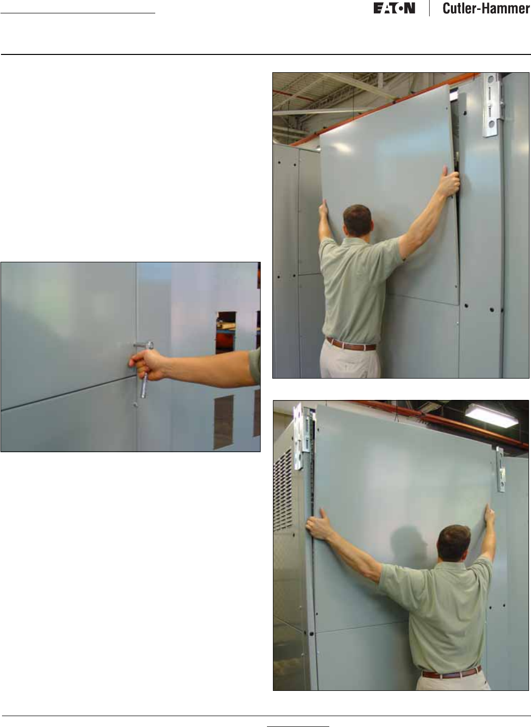
For more information visit: www.Eaton.com IB01602011E
Instructional Booklet
Page 32 Effective: March 2007 Fixed and Drawout Magnum Transfer Switches
9.3 Cover Removal and Replacement
Many of the maintenance procedures outlined in Table 6 require
the removal and replacement of side and rear covers. For all
NEMA 1 and NEMA 3R enclosed transfer switches, see
Section 9.3.1 for cover removal and replacement instructions.
9.3.1 Cover Removal and Replacement
A 3/8″ wrench or socket and ratchet is required to perform this
procedure.
Cover Removal
Step 1: Locate the bolts used to secure the cover to the frame
and remove them with the 3/8″ wrench. Remove the top
screws last while holding the cover in place (Figure 39).
Step 2: Allow the top of the cover to slowly tilt away from the
enclosure frame (Figure 40).
Step 3: Move your hands around to the sides and lift the cover
free (Figure 41).
Figure 39. Removing the Bolts.
Figure 40.Tilting the Cover Away from the Frame.
Figure 41. Lifting the Cover Free.
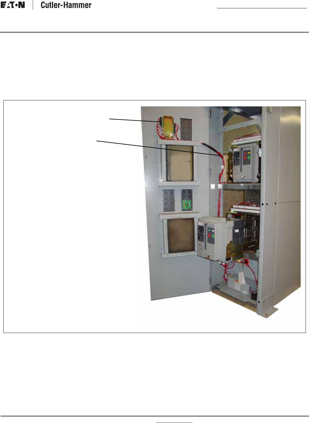
IB01602011E For more information visit: www.Eaton.com
Instructional Booklet
Effective: March 2007 Page 33
Fixed and Drawout Magnum Transfer Switches
Section 10: Renewal Parts Guide
10.1 General
Refer to Figure 42 through 45 for assistance with selecting and
ordering selected ATS renewal parts.
Example: To order Logic Harness for an ATVIMGB33200XRU
transfer switch, order Catalog Number T5MGH01 as shown in
Figure 42.
Figure 42.
ATC-600 CONTROLLER 2D7850G13
ATC-800 CONTROLLER 2D78580G03
Replacement parts not shown.
Non-Automatic Harness - T5MGH05
Bypass Harness - T5MGH08
LOGIC HARNESS TSMGH01
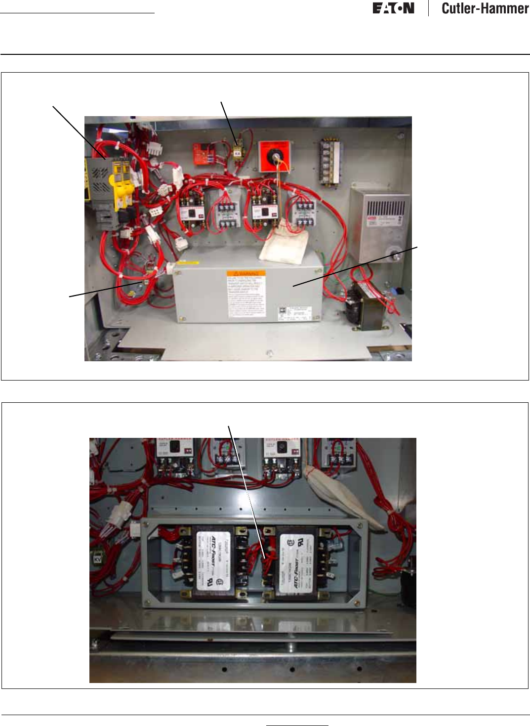
For more information visit: www.Eaton.com IB01602011E
Instructional Booklet
Page 34 Effective: March 2007 Fixed and Drawout Magnum Transfer Switches
Figure 43.
Figure 44.
SERVICE ENTRANCE FUSE
BLOCK HARNESS - TSMGH16 CLOSED TRANSITION
HARNESS TSMGH04
MAGNUM
NON-AUTO
TRANSFORMER
PACK TSMGT01
MAGNUM
DOMESTIC
TRANSFORMER
PACK TSMGT02
VOTING
HARNESS
TSHGH03
TRANSFORMER PACK HARNESS TSMGH16
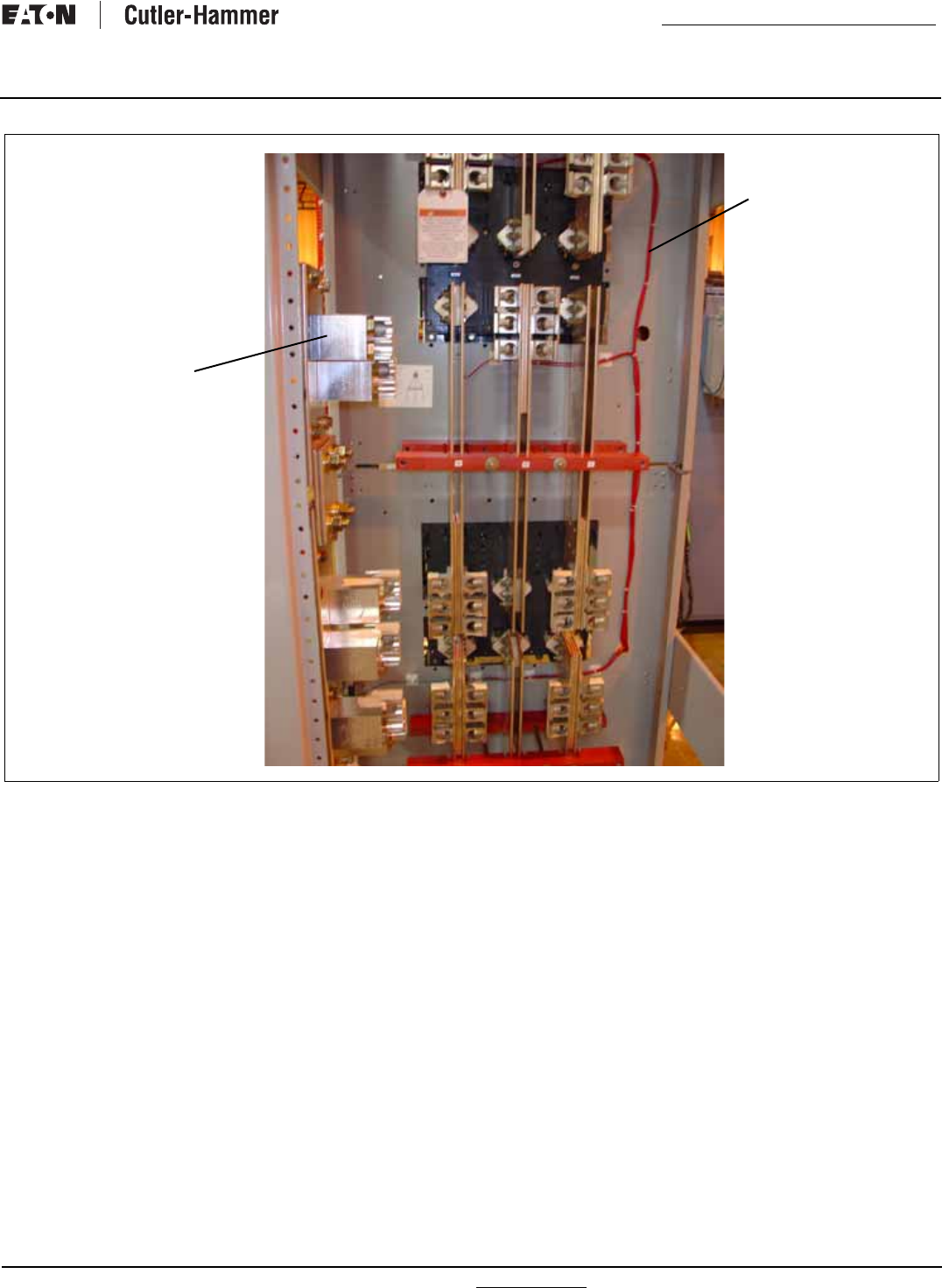
IB01602011E For more information visit: www.Eaton.com
Instructional Booklet
Effective: March 2007 Page 35
Fixed and Drawout Magnum Transfer Switches
Figure 45.
SENSING HARNESS
TSMGH02
500 KCMIL
NEUTRAL
TERMINAL
I80C046G02
OR
750 KCMIL
NEUTRAL
TERMINAL
I80C045G01

Instructional Booklet
Page 36 Effective: March 2007
© 2007 Eaton Corporation
All Rights Reserved
Printed in USA
Publication No. IB01602011E / TBG00140
March 2007
Fixed and Drawout Magnum Transfer Switches
This instruction booklet is published solely for information pur-
poses and should not be considered all-inclusive. If further infor-
mation is required, you should consult an authorized Eaton sales
representative.
The sale of the product shown in this literature is subject to the
terms and conditions outlined in appropriate Eaton selling policies
or other contractual agreement between the parties. This litera-
ture is not intended to and does not enlarge or add to any such
contract. The sole source governing the rights and remedies of
any purchaser of this equipment is the contract between the pur-
chaser and Eaton.
NO WARRANTIES, EXPRESSED OR IMPLIED, INCLUDING WAR-
RANTIES OF FITNESS FOR A PARTICULAR PURPOSE OR MER-
CHANTABILITY, OR WARRANTIES ARISING FROM COURSE OF
DEALING OR USAGE OF TRADE, ARE MADE REGARDING THE
INFORMATION, RECOMMENDATIONS, AND DESCRIPTIONS
CONTAINED HEREIN. In no event will Eaton be responsible to the
purchaser or user in contract, in tort (including negligence), strict
liability or otherwise for any special, indirect, incidental or conse-
quential damage or loss whatsoever, including but not limited to
damage or loss of use of equipment, plant or power system, cost
of capital, loss of power, additional expenses in the use of exist-
ing power facilities, or claims against the purchaser or user by its
customers resulting from the use of the information, recommen-
dations and description contained herein.
Eaton Corporation
Electrical Group
1000 Cherrington Parkway
Moon Township, PA 15108
United States
877-ETN CARE (877-386-2273)
Eaton.com
