Eaton s Cooper Power Systems EMS-H200 BlueMeter Hub Transceiver User Manual new
Eaton's Cooper Power Systems BlueMeter Hub Transceiver new
Users Manual Revised 061002

6/10/02
Eka Systems Proprietary 3/18
Hardware Setup
Guide
Eka Systems Inc.
444 N Frederic Ave • Suite 315 • Gaithersburg, MD 20877
Phone 301.990.3450 • Fax 301.990.3451
6/10/02
Eka Systems Proprietary 4/18
STEP 1 Identify the hardware
Identify the following components that are part of the BlueMeter Hub
package.
§ BlueMeter hub, with its attached Bluetooth dongle.
§ BlueMeter Module for the electric meter.
§ 5V DC adapter to power the BlueMeter hub.
§ CD media with the BlueMeterTM Network Manager software.
§ BlueMeterTM Network Manager User Guide.
STEP 2
Configuring the IP Address on the Hub
For connecting the Hub on to a LAN. Follow the procedure outlined in
this step.
Components required:
1. PC with Windows 95, Windows 98, Windows 2000, Windows NT
and Windows XP operating system.
2. PC must have an available serial port.
3. Network Manager Software CD.
4. 9-pin female-to-female null modem cable.
5. Two Ethernet cables for LAN connectivity.
6. Configuring the PC on the local LAN.
Configuring the IP address on the Hub.
1. Connect the PC on to a local LAN.
2. Install Network Manager Software on the PC.
3. Bring up the Network Manager software by selecting ‘Start-
>Programs->Eka Systems->BlueMeter Network Manager-
>Launch BlueMeter Network Manager’.

6/10/02
Eka Systems Proprietary 5/18
4. Connect the DC power cable (included) to the Hub.
5. Connect the other end of the DC power cable to the power outlet.
6. Connect the null modem cable to the available serial port on the PC
running the Network Manager and the ‘COM2’ port on the Hub.
(Null Modem cable not included).
7. Follow the steps outlined in Chapter 2 of the BlueMeter Network
Manager User Guide to add a Hub using a serial port connection as
shown in the picture below.
8. Once the Hub is added, double click on the Hub that is just added.
9. The user will be prompted to enter the username and password for
the Hub. (Use the username and password provided with the
Hardware setup guide).
10. The user will see the screen as shown in Figure 5 of the BlueMeter
Network Manager User Guide.
11. Click on ‘Set Hub IP Address’ from the Advanced Configuration
option.
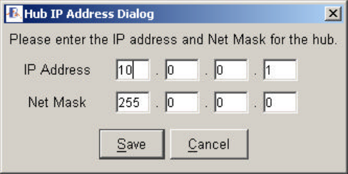
12. The ‘Set Hub IP Address’ button allows the user to enter an IP
address and a Netmask for the Hub Figure 1.
Figure 1 Set IP address dialog box
13. Enter the new IP address in this dialog box and save.
14. Once the IP address is configured, the Hub may be moved and
relocated to any desired spot, provided access to the LAN is available.
To Verify the IP address, please perform the following:
1. Remove the null modem cable between the PC and the Hub.
2. Using the Ethernet cable, connect Hub to the local LAN drop.
3. Follow steps outlined in Chapter 2 of the BlueMeter Network
Manager User Guide to ‘Configure the Hub’ to communicate over
the LAN.
4. Once the Hub is configured and added in the list of Hubs (with
Network option), follow steps in section 2.2 of the BlueMeter
Network Manager User guide to connect to a Hub.
6/10/02
Eka Systems Proprietary 6/18
STEP 3 Install the BlueMeter Module
The BlueMeter add-on card must always be installed as the innermost option
board (the board closest to the kV meter’s main board). Please refer to the
GEkV meter’s option board installation procedure to install the BlueMeter
add-on card. If there are any other option boards, install them above the
BlueMeter add-on card.
STEP 4 Additional connections
To access the hub from MeterMate through serial port, connect a null-
modem serial cable between the COM2 port on the hub and any COM port
on the PC. Please note that the serial port on the hub is configured to
communicate at 9600 baud.
FCC Notice
This device complies with Part 15 of the FCC Rules. Operation is subject to the following
two conditions: (1) this device may not cause harmful interference, and (2) this device must
accept any interference received, including interference that may cause undesired operation.
Changes or modifications not expressly approved by the manufacturer could void the user’s
authority to operate the equipment.
This equipment has been tested and found to comply with the limits for a Class B digital
device, pursuant to Part 15 of the FCC Rules. These limits are designed to provide
reasonable protection against harmful interference in a residential installation. This
equipment generates, uses and can radiate radio frequency energy and, if not installed and
used in accordance with the instructions, may cause harmful interference to radio
communications. However, there is no guarantee that interference will not occur in a
particular installation.
If this equipment does cause harmful interference to radio or television reception, which can be
determined by turning the equipment off and on, the user is encouraged to try to correct the
interference by one or more of the following measures:
-- Reorient or relocate the receiving antenna.
-- Increase the separation between the equipment and receiver.
-- Connect the equipment into an outlet on a circuit different from that to which the receiver is
connected.
-- Consult the dealer or an experienced radio/TV technician for help.