Echelon 70101-R002 Utility Network Telemetry and Control Device User Manual ECN 7000 Series Hardware and Installation Guide
Echelon Corporation Utility Network Telemetry and Control Device ECN 7000 Series Hardware and Installation Guide
Echelon >
Installation Guide
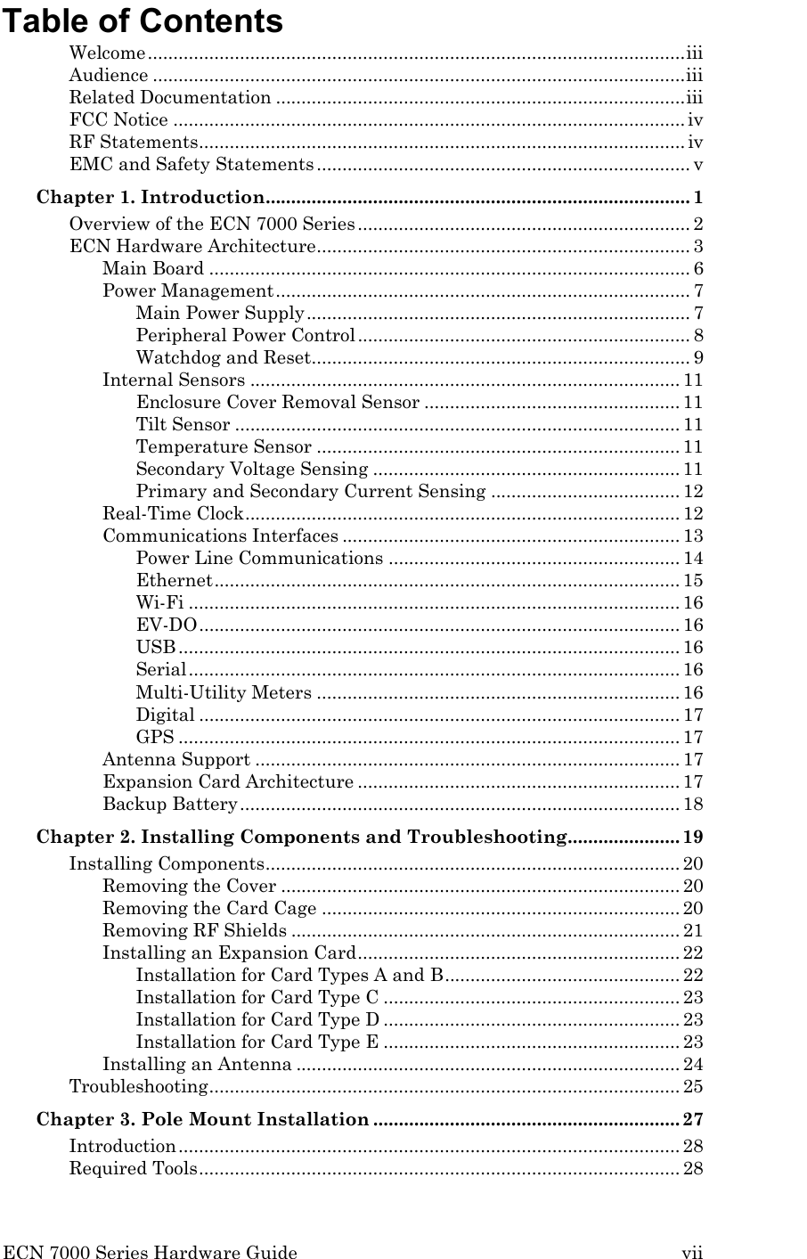
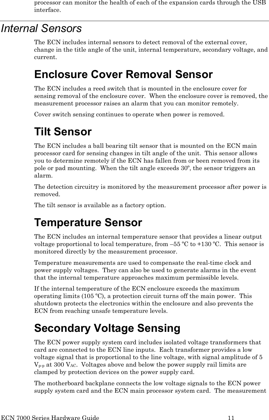
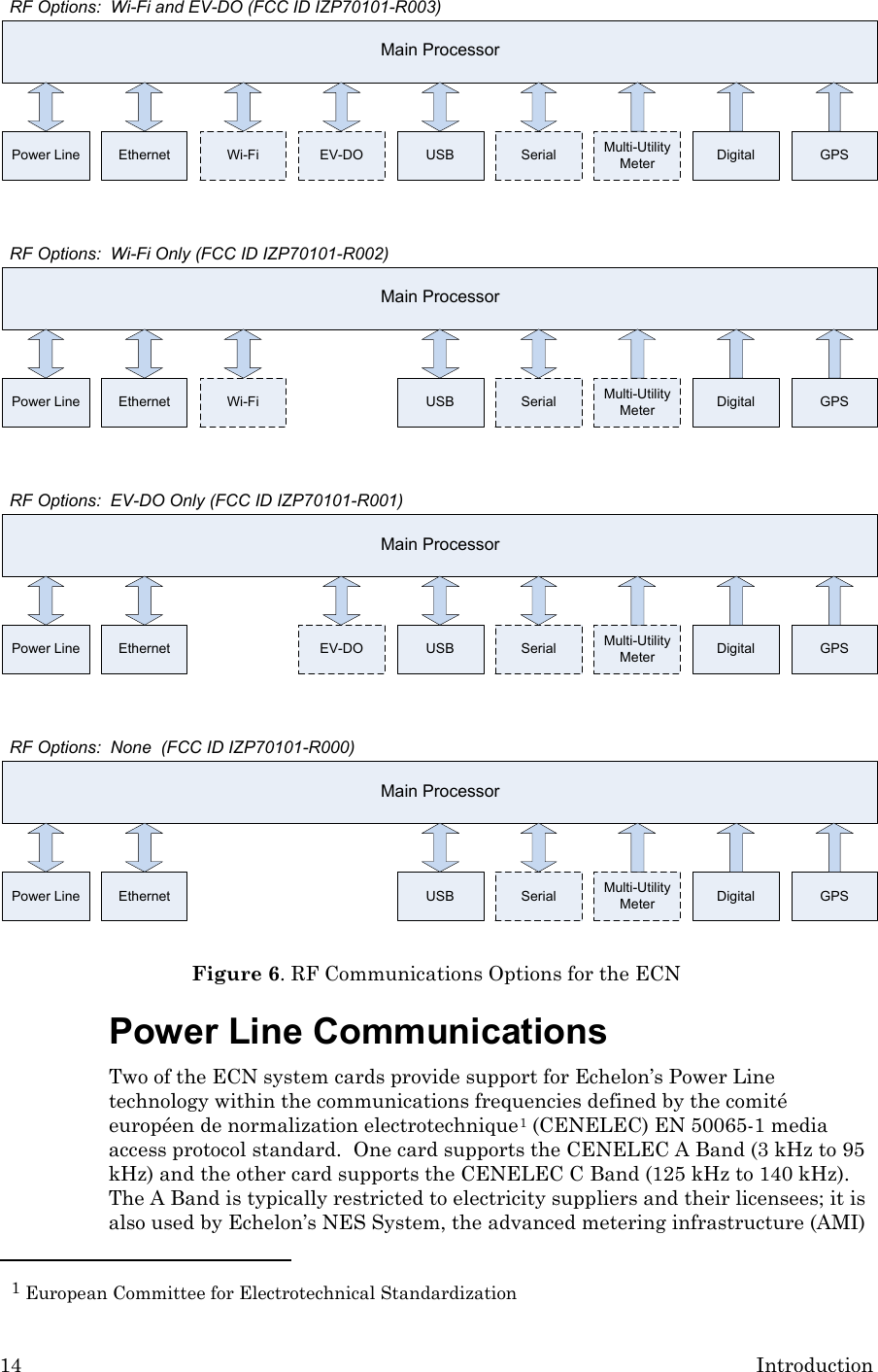
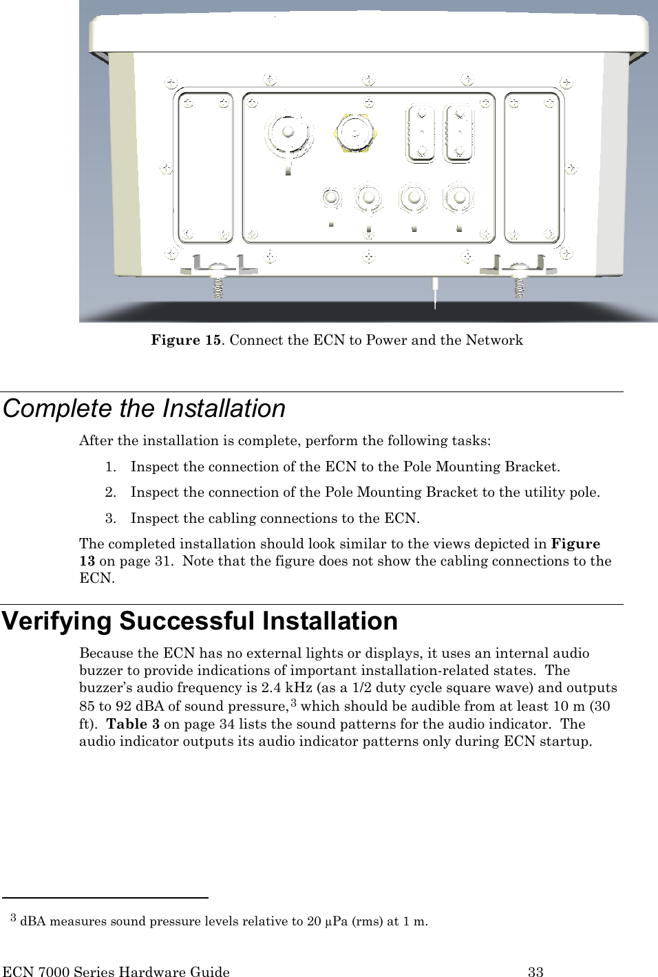
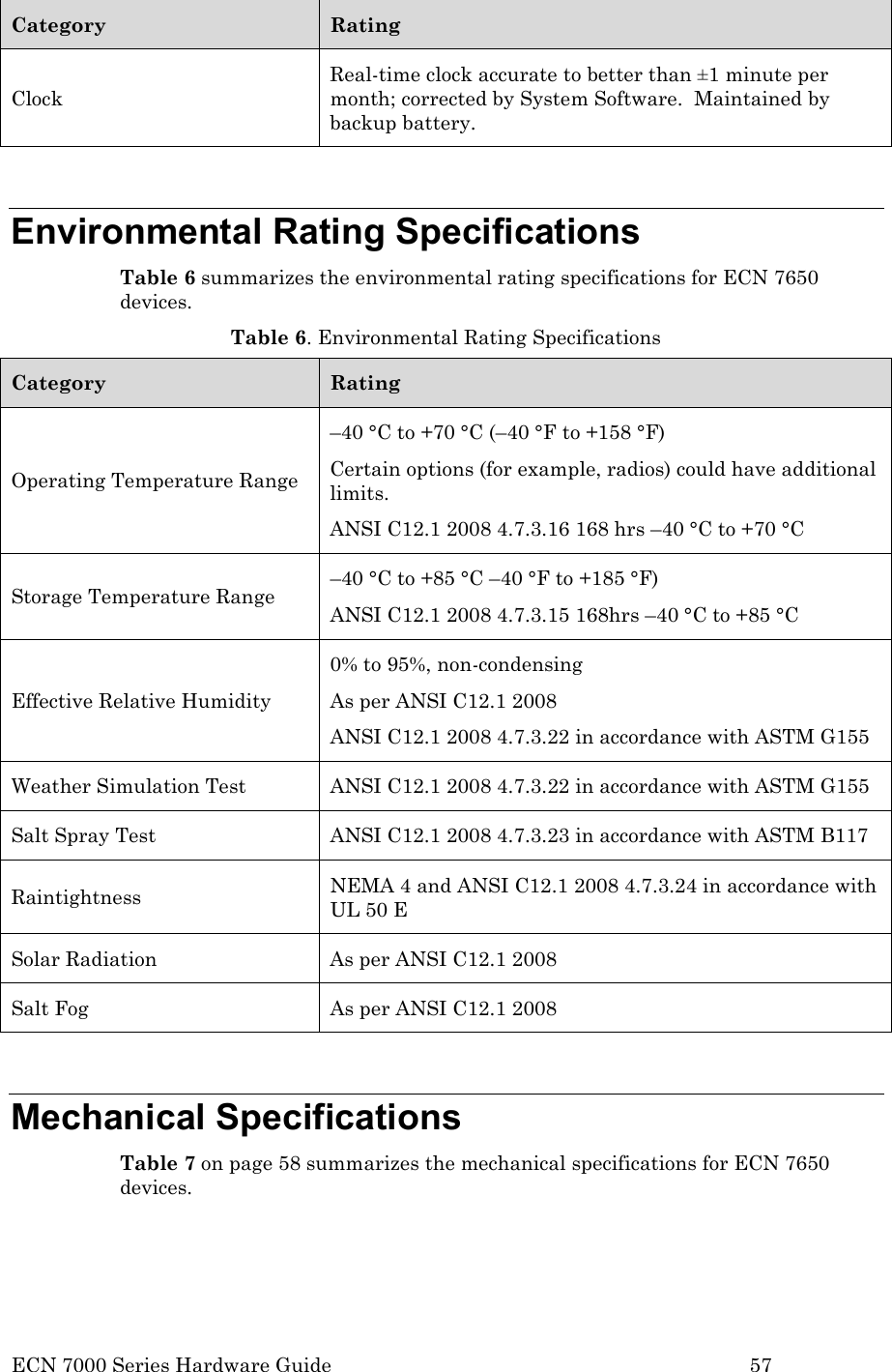
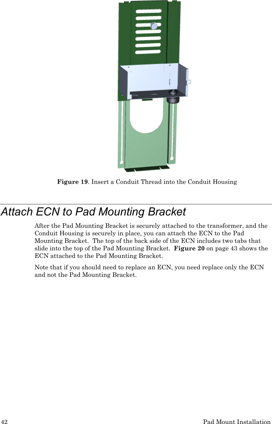
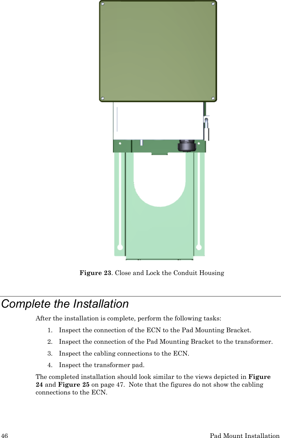
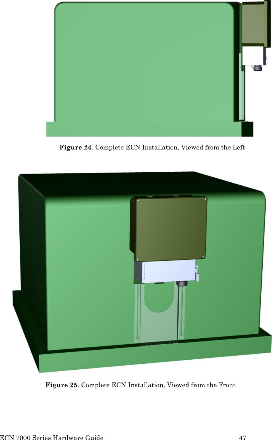
![38 Pad Mount Installation 4. Seal the top of the conduit inside the transformer cover with sealing putty or foam. This seal ensures that water and foreign objects cannot enter the transformer housing. 5. Seal the end of the conduit that is external to the transformer cover with sealing putty or foam. After the conduit and cabling are ready, you can install the ECN. See the next section, Performing the Installation. Performing the Installation To install the ECN using the pad mount method, perform the following tasks: 1. Extend the Pad Mounting Bracket 2. Attach the Pad Mounting Bracket to the transformer’s lifting nut 3. Attach the Conduit Housing to the Pad Mounting Bracket 4. Insert a Conduit Thread into the Conduit Housing 5. Attach the ECN to the Pad Mounting Bracket 6. Secure the ECN to the Pad Mounting Bracket 7. Connect the ECN to power and to the network 8. Close and lock the Conduit Housing 9. Complete the installation Each of these tasks is described in the following sections. Extend Pad Mounting Bracket You connect the ECN to the transformer using the transformer’s lifting nut, as described in Attach Pad Mounting Bracket to Lifting Nut on page 39. The Pad Mounting Bracket is designed to secure the ECN to the transformer’s lifting nut, regardless of the location of the lifting nut. The Pad Mounting Bracket is vertically adjustable (from approximately 46 cm [18 inches] to 92 cm [36 inches]) so that you can match the 1.9 cm (3/4 inch) horizontal slots with the position of the transformer lifting nut. Figure 16 on page 39 shows the Pad Mounting Bracket fully extended.](https://usermanual.wiki/Echelon/70101-R002/User-Guide-1495342-Page-46.png)
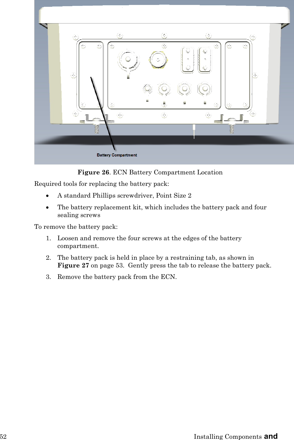
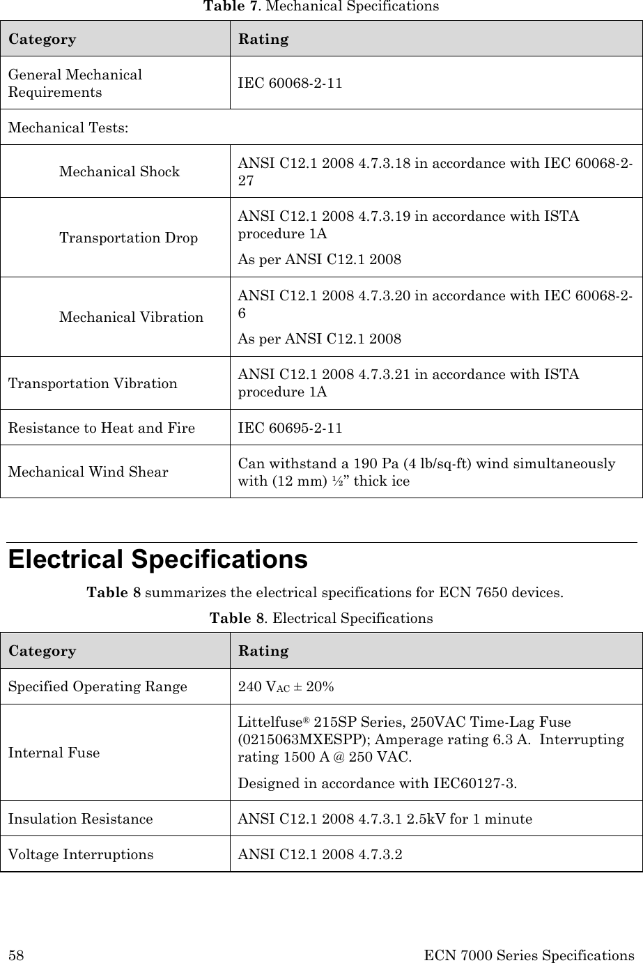
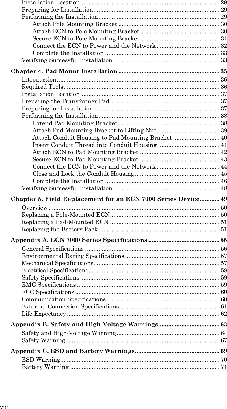
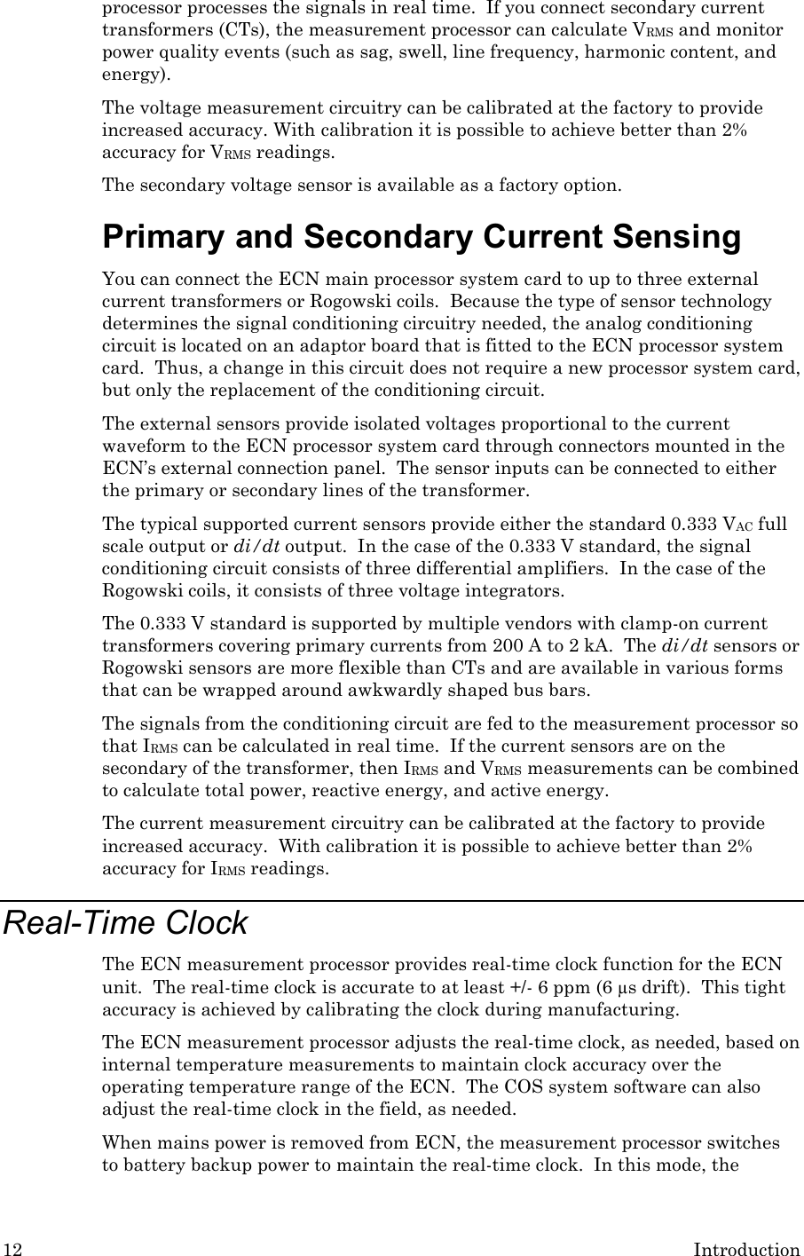
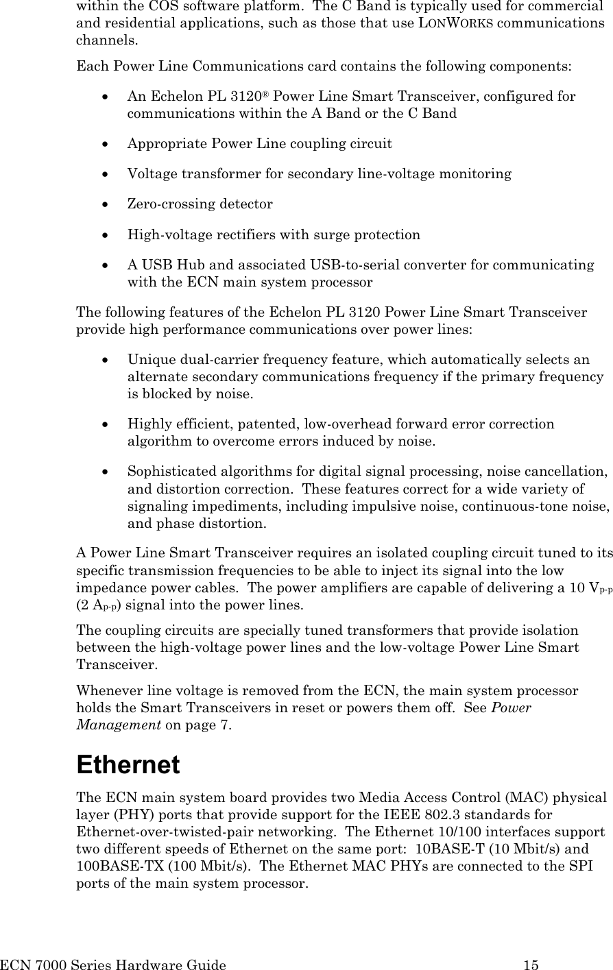
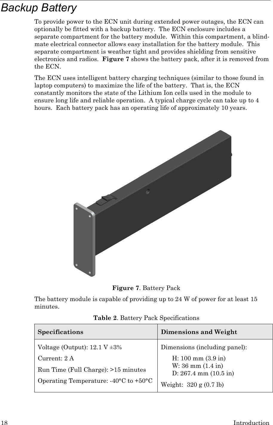
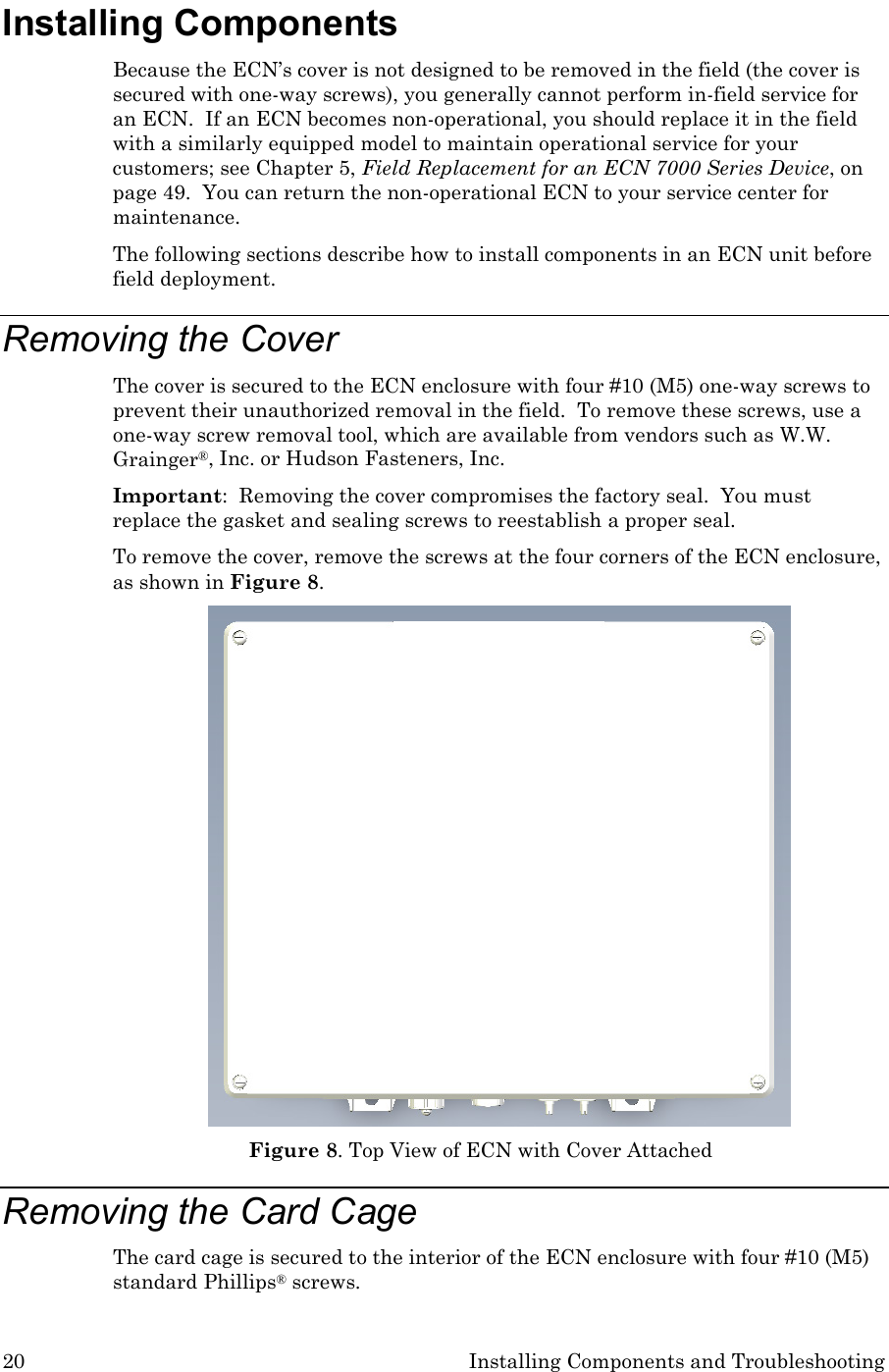
![ECN 7000 Series Hardware Guide 53 Figure 27. Battery Pack Restraining Tab To replace the battery pack: 1. Insert the battery pack into the battery compartment. The restraining tab must be oriented toward the ECN cover. The restraining tab will click into place. 2. Ensure that the battery pack’s gasket makes a good seal with the battery compartment. 3. Insert and tighten the four sealing screws. Tighten the screws in a diagonal “X” pattern (alternating top-left, bottom-right, top-right, bottom-left). Tighten the screws to no more than 9.1 (±0.4) lbf-in (10.4 [±0.5] kgf-cm) torque.](https://usermanual.wiki/Echelon/70101-R002/User-Guide-1495342-Page-61.png)