Echelon 70101-0002 Utility Control Network Device User Manual Edge Control Node 7000 Series Installation Guide
Echelon Corporation Utility Control Network Device Edge Control Node 7000 Series Installation Guide
Echelon >
User Manual
@echelon®
Edge Control Node 7000 Series
Installation Guide
FIRST REVIEW DRAFT
078-xxxx-01A

Echelon, LONWORKS, and the Echelon logo are trademarks of
Echelon Corporation registered in the United States and
other countries.
Other brand and product names are trademarks or
registered trademarks of their respective holders.
Smart Transceivers, Neuron Chips, and other OEM Products
were not designed for use in equipment or systems, which
involve danger to human health or safety, or a risk of
property damage and Echelon assumes no responsibility or
liability for use of the Smart Transceivers or Neuron Chips in
such applications.
Parts manufactured by vendors other than Echelon and
referenced in this document have been described for
illustrative purposes only, and may not have been tested
by Echelon. It is the responsibility of the customer to
determine the suitability of these parts for each
application.
ECHELON MAKES AND YOU RECEIVE NO WARRANTIES OR
CONDITIONS, EXPRESS, IMPLIED, STATUTORY OR IN ANY
COMMUNICATION WITH YOU, AND ECHELON SPECIFICALLY
DISCLAIMS ANY IMPLIED WARRANTY OF MERCHANTABILITY
OR FITNESS FOR A PARTICULAR PURPOSE.
No part of this publication may be reproduced, stored in a
retrieval system, or transmitted, in any form or by any means,
electronic, mechanical, photocopying, recording, or
otherwise, without the prior written permission of Echelon
Corporation.
Printed in the United States of America.
Copyright © 2010 Echelon Corporation.
Echelon Corporation
www.echelon.com

Edge Control Node 7000 Series Installation Guide iii
Welcome
To improve both reliability and efficiency, national and regional power
distribution grids must become smarter. They must also be able to manage
themselves using intelligent distributed control and be able to communicate with
any device, over any network or protocol, to optimize grid operations and
anticipate problems before they occur.
The Echelon® Edge Control Node (ECN) 7000 Series of open and extensible
hardware products enable power distribution grids to become smarter. The ECN
7000 Series distributes the intelligence that public and private electrical power
utilities need to monitor and control devices at the edge of the grid. The edge of
the grid is the critical point where the distribution network connects to customers
and where energy supply and demand are becoming increasingly unpredictable
and complex.
The ECN 7000 Series is powered by the Echelon Control System (ECoS) software
platform, which is part of the Echelon Networked Energy Services (NES) system.
ECoS software provides an open, secure, and modular software framework that
allows you to host hundreds of new applications that are needed for a smarter
grid. This powerful hardware and software combination brings intelligent
distributed control to the edge of the grid for maximum reliability, survivability,
and responsiveness.
This manual describes how a utility worker installs an ECN 7650 device on a
utility power pole or a transformer pad.
Audience
This document assumes that you have a good understanding of medium (<50 kV)
and low (<1 kV) power electrical power distribution grids. You should be able to
make electrical connections to medium and low power distribution transformers,
and be able to make physical connections for electrical devices within the
medium and low power electrical distribution grid. You must also understand
the safety requirements for working within this environment.
Related Documentation
The following manuals are available from the Echelon Web site
(www.echelon.com) and provide additional information that can help you deploy
Edge Control Node devices and develop applications for them:
•
Edge Control Node 7000 Series Hardware Guide
(078-xxxx-01A). This
manual describes the hardware for the ECN.
•
Edge Control Node 7000 Series Expansion Card Development Guide
(078-
xxxx-01A). This manual describes the functional requirements for third-
party development of expansion cards that plug into the ECN 7000 Series
of products.
•
ECoS User's Guide
(078-xxxx-01A). This document describes how to
configure the i.LON SmartServer and use its applications to manage
control networks.

iv
•
ECoS Power Line Repeating Guide
(078-xxxx-01A). This document
describes how to manage, control, and monitor a power line repeating
network using the SmartServer.
•
ECoS Vision User’s Guide
(078-xxxx-01A). This document describes how
to create custom Web pages for monitoring and controlling LONWORKS®
networks and other control networks.
•
ECoS App Programming Tools User’s Guide
(078-xxxx-01A). This guide
describes how to create and use FPMs on your SmartServer, and how to
localize the language of the SmartServer Web interface.
•
Introduction to the LONWORKS Platform
(078-0183-01B)
.
This manual
provides an introduction to the ISO/IEC 14908-1 (ANSI/CEA-709.1 and
EN14908) Control Network Protocol, and provides a high-level
introduction to LONWORKS networks and the tools and components that
are used for developing, installing, operating, and maintaining them.
All of the Echelon documentation is available in Adobe® PDF format. To view the
PDF files, you must have a current version of the Adobe Reader®, which you can
download from Adobe at: get.adobe.com/reader.
FCC Compliance Notice
Federal Communications Commission Radio Frequency Interference Statement
This equipment has been tested and found to comply with the limits for a Class B
digital device pursuant to Part 15 of the FCC Rules, per sections 15.107 and
15.109. These limits are designed to provide reasonable protection against
harmful interference in a residential installation. This equipment generates,
uses, and can radiate radio frequency energy and, if not installed and used in
accordance with the manufacturer’s instruction manual, may cause interference
with radio communications. However, there is no guarantee that interference
will not occur in a particular installation. If this equipment does cause harmful
interference to radio or television reception, which can be determined by turning
the equipment off and on, you are encouraged to try to correct the interference by
one or more of the following measures:
• Reorient or relocate the receiving antenna.
• Increase the separation between the equipment and the receiver.
• Connect the equipment into an outlet on a circuit different from that
which the receiver is connected.
• Consult the dealer or an experienced radio/television technician for
help.
Changes or modifications not expressly approved by Echelon Corporation could
void the user’s authority to operate the equipment.
RF Statements
This equipment also complies with the limits for wireless devices per FCC
sections 15.203, 15.205, 15.207, 15.209 and 15.247. It uses frequency 2.4 GHz
per Institute of Electrical and Electronics Engineers (IEEE) standard 802.15.4-
2006, and uses a frequency bandwidth from 2400 MHz to 2483.5 MHz.

Edge Control Node 7000 Series Installation Guide v
This equipment complies with the FCC RF radiation exposure limits set forth for
an uncontrolled environment. This equipment should be installed and operated
with a minimum distance of 20 centimeters between the radiator and your body.
This transmitter must not be co-located or operating in conjunction with any
other antenna or transmitter.
EMC and Safety Statements
TBD
TÜV Certified per EN 60950, 2000, IEC60950, 2000,
UL60950, and CSA60950 by TÜV under NRTL
Declaration of Conformity
To Be Added
89/336/EEC, Electromagnetic Compatibility Directive (EMC), 73/23/EEC, Low
Voltage Directive (LVD)

Edge Control Node 7000 Series Installation Guide vii
Table of Contents
Welcome.........................................................................................................iii
Audience ........................................................................................................iii
Related Documentation ................................................................................iii
FCC Compliance Notice................................................................................iv
RF Statements...............................................................................................iv
EMC and Safety Statements......................................................................... v
Declaration of Conformity ............................................................................. v
Introduction........................................................................................................ 1
Introduction to the Edge Control Node ........................................................2
Pole Mount Installation ..................................................................................... 3
Introduction....................................................................................................4
Required Tools................................................................................................4
Installation Location...................................................................................... 5
Preparing for Installation..............................................................................5
Performing the Installation...........................................................................5
Attach Pole Mounting Bracket ...............................................................6
Attach ECN to Pole Mounting Bracket..................................................6
Secure ECN to Pole Mounting Bracket.................................................. 7
Connect the ECN to Power and the Network........................................8
Complete the Installation ....................................................................... 9
Verifying Successful Installation ..................................................................9
Pad Mount Installation.................................................................................... 11
Introduction..................................................................................................12
Required Tools..............................................................................................12
Installation Location....................................................................................13
Preparing the Transformer Pad..................................................................13
Preparing for Installation............................................................................13
Performing the Installation.........................................................................14
Extend Pad Mounting Bracket .............................................................14
Attach Pad Mounting Bracket to Lifting Nut......................................15
Attach Conduit Housing to Pad Mounting Bracket ............................16
Insert Conduit Thread into Conduit Housing .....................................17
Attach ECN to Pad Mounting Bracket................................................. 18
Secure ECN to Pad Mounting Bracket ................................................19
Connect the ECN to Power and the Network......................................20
Close and Lock the Conduit Housing ...................................................21
Complete the Installation ..................................................................... 22
Verifying Successful Installation ................................................................24
Field Replacement for an ECN 7000 Series Device........................................ 25
Overview.......................................................................................................26
Replacing a Pole-Mounted ECN..................................................................26
Replacing a Pad-Mounted ECN ..................................................................27
Replacing the Battery Pack.........................................................................27
ECN 7000 Series Specifications....................................................................... 31
General Specifications .................................................................................32
Environmental Rating Specifications......................................................... 33
Mechanical Specifications............................................................................34
Electrical Specifications...............................................................................35
viii
Safety Specifications ....................................................................................35
EMC Specifications ......................................................................................36
FCC Specifications .......................................................................................37
Communications Specifications ..................................................................37
External Connection Specifications ............................................................ 37
Life Expectancy ............................................................................................39
Safety and High-Voltage Warnings................................................................. 41
Safety and High-Voltage Warning..............................................................42
Safety Warning ............................................................................................44
ESD and Battery Warnings............................................................................. 45
ESD Warning ...............................................................................................46
Battery Warning ..........................................................................................46
Edge Control Node 7000 Series Installation Guide 1
1
Introduction
This chapter introduces the Edge Control Node 7000 Series
of products.

2 Introduction
Introduction to the Edge Control Node
Residential and commercial energy customers are increasingly focused energy
efficiency and reliability, while also reducing the environmental impact of
electricity use. National and regional power distribution grids in the 21st century
must address these customer concerns, while at the same time monitoring
electricity as it flows through many types of devices and transmission media
(substation elements, high, medium, and low voltage power lines, capacitor
banks, transformers, meters, communicating thermostats, load-control devices,
and so on).
A modern smart power grid network must be able to manage itself using
intelligent distributed control and be able to communicate with any device, over
any network or protocol, to optimize grid operations and anticipate problems
before they occur.
The Echelon Edge Control Node (ECN) 7000 Series of open and extensible
hardware products enable power distribution grids to become smarter. The ECN
7000 Series distributes the intelligence that public and private electrical power
utilities need to monitor and control devices at the edge of the grid. The edge of
the grid is the critical point where the distribution network connects to customers
and where energy supply and demand are becoming increasingly unpredictable
and complex.
The ECN 7000 Series of products use the Echelon Control System (ECoS)
software platform, which provides the open, secure and modular software
framework needed to host hundreds of new applications needed for a smarter
grid. This powerful combination of hardware and software brings intelligent
distributed control to the edge of the grid for maximum reliability, survivability
and responsiveness.
The ECN 7650 is the first member of the ECN 7000 Series of products. The ECN
7650 supports a variety of local, wide-area, and device radio frequency (RF)
networks, with up to nine antennas, all contained within the ECN 7650 enclosure
to reduce vandalism and security risks.
The cover of the ECN 7650 is secured with one-way screws, which virtually
eliminates unauthorized access. When the ECN 7650 is pad mounted, you secure
the power and network connections inside a metal housing with a padlock. The
ECN 7650 is also rugged and sturdy enough to allow a person (for example, a
utility working gaffing a utility pole) to stand on it.
The ECN 7650 is designed for quick and secure installation using a rapid-mount
bracket on either a utility pole or a pad-mounted distribution transformer.
Because the ECN 7650 is small enough (H: 305 mm, 12 in – W: 356 mm, 14 in –
D: 178 mm, 7 in) and light enough (<5.4 kg, <12 lb) to hand carry, installation is
simple and easy.
The rest of this manual describes how to install the ECN 7650, either to a utility
pole or to a pad-mounted distribution transformer.
Edge Control Node 7000 Series Installation Guide 3
2
Pole Mount Installation
This chapter describes how to install the ECN on a utility pole.

4 Pole Mount Installation
Introduction
You can install an ECN on any standard utility pole, in either the supply space or
the common area. The ECN provides a carrying loop that you can tie with a rope
so that you can easily carry the ECN while climbing the pole. The ECN is also
small and light enough that you can carry it while working from a boom lift.
After installation, the ECN can withstand a 1330 J/m (300 ft-lb) force, for
example, from a utility worker standing on the unit. The ECN is designed to be
small enough that a utility worker can gaff up the pole and around the unit with
minimal difficulty.
The installation includes a bracket that you attach to the utility pole. You then
attach the ECN to the installed bracket. Subsequent replacement or installation
of an ECN can reuse the installed bracket, thus substantially reducing
replacement installation time and effort. In addition, you can connect or
disconnect the ECN from either power or the communications network easily,
without having to uninstall the entire unit.
Required Tools
To perform the installation for the ECN and the Pole Mounting Bracket, you will
need the following tools:
• A drill, with drill bit appropriate for a 1.6 cm (5/8 inch) diameter bolt that
is 12 to 70 cm (4.5 to 27.5 inches) in length
• A 1.6 cm (5/8 inch) wrench
• A wire stripping tool
• A fiberglass or plastic cable puller tool
• A standard Phillips® screwdriver, Point Size 2
In addition to the tools listed above, you need an ECN Pole Mount Kit, which
includes the following components:
• Pole Mounting Bracket
• Support bolt: 12 to 70 cm (4.5 to 27.5 inches) in length (depends on the
pole class and the planned installation height for the ECN), 1.6 cm (5/8
inch) in diameter
• Two 1.6 cm (5/8 inch) washers
• One 1.6 cm (5/8 inch) square-head nut
• Input power cable accessory:
o The input power cable accessory is available in three lengths: 3
m, 9 m, and 12 m (10 ft, 30 ft, and 40 ft).
o The cable type conforms to the specifications for 2.05 mm (12
AWG) stranded copper conductors. Two conductors are covered
with black UV jacket insulation (600 V rating), and one with
white UV jacket insulation (600 V rating).
o The end of the cable that connects to the ECN input power
connector is fitted. The other end of the cable is not fitted.

Edge Control Node 7000 Series Installation Guide 5
Installation Location
Typically, you install the ECN on a utility pole either in the supply space (near
the service distribution transformer) or in the common area (3-½ to 4-½ meters or
12 to 15 feet above ground level).
Important: Do not install the ECN in the communication space; that space is
reserved for cable, telephone, and other companies to install their equipment.
For optimal antenna performance, you should place the ECN as high on the
utility pole as possible, in the supply space. However, many installations will
install the ECN common area: installation in the common area is typically easier
to perform, less expensive, and involves less risk for the installer.
Preparing for Installation
After you have selected the installation location on the utility pole (within the
supply space or in the common area), determine the distance from the low-
voltage (LV) attachment point (typically at or near the service distribution
transformer) and the proposed installation point for the ECN. If the ECN input
power cable is shorter than this distance, splice an additional length of cable and
weather seal that splice.
When the ECN is installed in the common area, the input power cable must be
shielded in a protective conduit to protect the input power cable from
communications workers and other personnel who climb the pole. When the
ECN is installed in the supply space, this protective conduit is not necessary.
You can use a simple vertical wire guard, but generally you should use Schedule
40 conduit.1 Leave both the top and bottom of the conduit open so that water can
flow freely through the conduit. The bottom end of the conduit should terminate
near the ECN, but should not be attached to it. Feed the input power cable
through the conduit and connect it to an available power source.
Drill a hole through the utility pole. The diameter of this hole should be able to
fit a 1.6 cm (5/8 inch) diameter bolt securely. The hole should be centered
horizontally with respect to the pole diameter, and should be centered vertically
with respect to the planned location of the ECN.
Performing the Installation
To install the ECN using the pole mount method, perform the following tasks:
1. Attach the Pole Mounting Bracket to the pole
2. Attach the ECN to the Pole Mounting Bracket
3. Secure the ECN to the Pole Mounting Bracket
4. Connect the ECN to power and to the network
5. Complete the installation
Each of these tasks is described in the following sections.
1 See UL 651, NEMA TC-2, or NEC-Article 352 for Schedule 40 specifications.
6 Pole Mount Installation
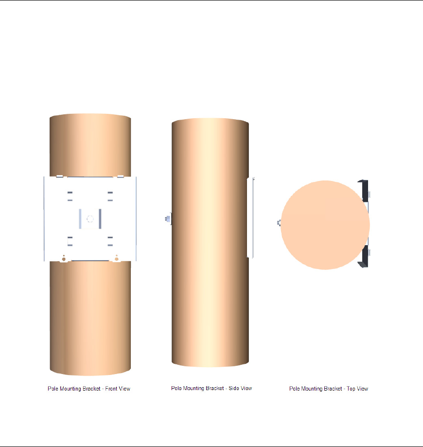
Attach Pole Mounting Bracket
You connect the ECN to the utility pole using the hole that you drilled into the
pole to prepare for installation; see
Preparing for Installation
on page 5. Place
the bracket against the pole, insert the support bolt, and secure the bolt with a
washer and nut, as shown in Figure 1. The Pole Mounting Bracket is designed to
fit any standard utility pole.
Figure 1. Attach Pole Mounting Bracket
Attach ECN to Pole Mounting Bracket
After the Pole Mounting Bracket is securely attached to the utility pole, you can
attach the ECN to the Pole Mounting Bracket. The top of the back side of the
ECN includes two tabs that slide into the top of the Pole Mounting Bracket.
Figure 2 on page 7 shows the ECN attached to the Pole Mounting Bracket.
Note that if you should need to replace an ECN, you need replace only the ECN
and not the Pole Mounting Bracket.
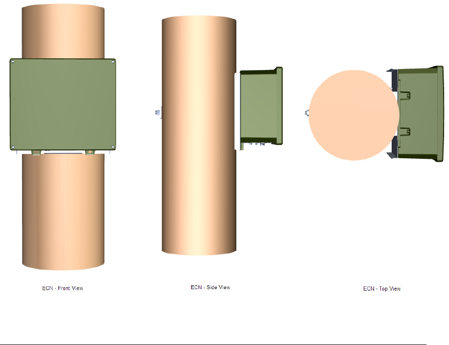
Edge Control Node 7000 Series Installation Guide 7
Figure 2. Attach the ECN to the Pole Mounting Bracket
Secure ECN to Pole Mounting Bracket
To secure the ECN to the Pole Mounting Bracket, insert two screws to the bottom
of the ECN to attach it to the Pole Mounting Bracket. These screws are already
connected to the ECN, and are designed not to make contact with the pole.
Figure 3 on page 8 shows a front view of the ECN attached to the Pole Mounting
Bracket, with the bottom screws visible.
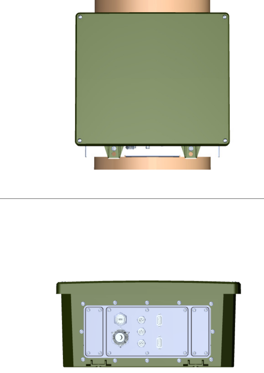
8 Pole Mount Installation
Figure 3. Secure the ECN to the Pole Mounting Bracket
Connect the ECN to Power and the Network
You make the connections to power and to the communications network at the
bottom of the ECN. Figure 4 shows the bottom of the ECN, before installation.
You can connect the ECN to either low voltage or medium voltage.
The exact configuration of the ECN bottom panel depends on the options that you
have installed in the ECN, but at a minimum, the bottom panel has a connection
for power and for at least one communications network. In the figure, the bottom
left connection is for power.
Figure 4. Connect the ECN to Power and the Network

Edge Control Node 7000 Series Installation Guide 9
Complete the Installation
After the installation is complete, perform the following tasks:
1. Inspect the connection of the ECN to the Pole Mounting Bracket.
2. Inspect the connection of the Pole Mounting Bracket to the utility pole.
3. Inspect the cabling connections to the ECN.
The completed installation should look similar to the views depicted in Figure 2
on page 7. Note that the figure does not show the cabling connections to the
ECN.
Verifying Successful Installation
Because the ECN has no external lights or displays, it uses an internal audio
buzzer to provide indications of important installation-related states. The
buzzer’s audio frequency is 2.4 kHz (as a 1/2 duty cycle square wave) and outputs
85 to 92 dBA of sound pressure,2 which should be audible from at least 10 m (30
ft). Table 1 lists the sound patterns for the audio indicator. The audio indicator
outputs its audio indicator patterns once only.
Table 1. Internal Audio Indicator Sound Patterns
Sound Pattern
On (ms) Off (ms) Repeat Description
1000 0 1 ECN first starts up
1000 0 1 ECN main processor starts running
1000 500 3 Successful direct WAN connection
1000 500 6 Successful indirect WAN connection
4000 500 2 No WAN connection made
As the table shows, a successful installation should include two 1 second sound
bursts and at least one repeated pattern (1 s on, 0.5 s off) to indicate a successful
network connection. If you receive the repeated pattern (4 s on, 0.5 s off) that
indicates unsuccessful network connection, check the network cable connection
and verify that the network is operational.
After installation is verified successful, use the ECoS Web page interface for the
ECN to verify additional functionality. You might also want to disable the
internal audio indicator so that subsequent resets or power events do not cause
the audio indicator to output its audio indicator patterns.
2 dBA measures sound pressure levels relative to 20 μPa (rms) at 1 m.
Edge Control Node 7000 Series Installation Guide 11
3
Pad Mount Installation
This chapter describes how to install the ECN on a service
distribution transformer that is mounted on a concrete pad.

12 Pad Mount Installation
Introduction
You can install an ECN on the same concrete pad as a service distribution
transformer, and secure it to the transformer without drilling holes into or
otherwise damaging the transformer housing. After installation, the ECN is
resistant to manual removal, and none of the electrical or communications
network connections can be accessed by unauthorized personnel.
The installation includes a bracket that you attach to the transformer housing
and concrete pad. You then attach the ECN to the installed bracket. Subsequent
replacement or installation of an ECN can reuse the installed bracket, thus
substantially reducing replacement installation time and effort. In addition, you
can connect or disconnect the ECN from either power or the communications
network easily, without having to uninstall the entire unit.
Required Tools
To perform the installation for the ECN and the Pad Mounting Bracket, you will
need the following tools:
• A 1.6 cm (5/8 inch) wrench
• A wire stripping tool
• A fiberglass or plastic cable puller tool
• A standard Phillips® screwdriver, Point Size 2
• A shovel (hand or power) or similar digging tool
• Standard conduit sealing putty or foam
In addition to the tools listed above, you need an ECN Pad Mount Kit, which
includes the following components:
• Pad Mounting Bracket
• Conduit Housing
• Connection bolt: 5 cm (2 inches) in length, 1.6 cm (5/8 inch) in diameter
• A 1.6 cm (5/8 inch) washer
• Two 1.6 cm (5/8 inch) concrete-compatible bolt kits
• Input power cable accessory:
o The input power cable accessory is available in three lengths: 3
m, 9 m, and 12 m (10 ft, 30 ft, and 40 ft).
o The cable type conforms to the specifications for 2.05 mm (12
AWG) stranded copper conductors. Two conductors are covered
with black UV jacket insulation (600 V rating), and one with
white UV jacket insulation (600 V rating).
o The end of the cable that connects to the ECN input power
connector is fitted. The other end of the cable is not fitted.

Edge Control Node 7000 Series Installation Guide 13
Installation Location
For optimal antenna performance, you should place the ECN as high on the
distribution transformer as possible. However, most installations will require
that the top of the ECN after installation extend no higher than the top of the
transformer. A typical residential transformer measures between 46 cm (18
inches) and 74 cm (29 inches) in height. If you place the ECN exactly even with
the top of the transformer, you have between 15 cm (6 inches) and 43 cm (17
inches) clearance from the transformer pad to the bottom of the ECN. For most
installations, this clearance is sufficient to connect the installed ECN to external
power and the communication network.
Installation rules also typically require that the top of the 1.9 cm or 3.2 cm (¾” or
1-1/4”) flexible conduit should be at least 7.6 cm (3 inches) above grade level to
prevent water ingress into the conduit. That is, there must be at least 7.6 cm (3
inches) of clearance from the bottom locking nut on the outside of the 1.9 cm or
3.2 cm (¾” or 1-1/4”) flexible conduit.
Preparing the Transformer Pad
To prepare to connect the ECN to the power mains at the transformer, perform
the following tasks:
1. Open the transformer cover to determine the location of an unused pre-
cored hole in the transformer pad. This hole must be large enough to
accommodate the 1.9 cm or 3.2 cm (¾” or 1-1/4”) flexible conduit for the
ECN.
2. Use a shovel or similar tool to dig under the transformer pad to clear
space for the conduit.
3. Fit the conduit up and into the hole.
4. Position the conduit as near to the lifting nut on the side of the
transformer as possible. Ideally, the conduit should be positioned
vertically under the lifting nut.
5. Cut to the conduit to the approved length.
6. Replace the dirt below the transformer pad.
7. Close the transformer cover.
Preparing for Installation
After you prepare the transformer pad, you can complete installation preparation
by performing the following steps:
1. Use a cable stripping tool to strip approximately 45 cm (18 inches) of the
insulating jacket from all three conductors of the non-fitted end of the
power cable.
2. Use a fiberglass or plastic cable puller tool to thread the power cable
though the conduit that you prepared in the previous section,
Preparing
the Transformer Pad
.
3. On the transformer side, attach the cables to the transformer so that they
can provide power to the ECN.

14 Pad Mount Installation
4. Seal the top of the conduit inside the transformer cover with sealing
putty or foam. This seal ensures that water and foreign objects cannot
enter the transformer housing.
5. Seal the end of the conduit that is external to the transformer cover with
sealing putty or foam.
After the conduit and cabling are ready, you can install the ECN. See the next
section,
Performing the Installation
.
Performing the Installation
To install the ECN using the pad mount method, perform the following tasks:
1. Extend the Pad Mounting Bracket
2. Attach the Pad Mounting Bracket to the transformer’s lifting nut
3. Attach the Conduit Housing to the Pad Mounting Bracket
4. Insert a Conduit Thread into the Conduit Housing
5. Attach the ECN to the Pad Mounting Bracket
6. Secure the ECN to the Pad Mounting Bracket
7. Connect the ECN to power and to the network
8. Close and lock the Conduit Housing
9. Complete the installation
Each of these tasks is described in the following sections.
Extend Pad Mounting Bracket
You connect the ECN to the transformer using the transformer’s lifting nut, as
described in
Attach Pad Mounting Bracket to Lifting Nut
on page 15. The Pad
Mounting Bracket is designed to secure the ECN to the transformer’s lifting nut,
regardless of the location of the lifting nut.
The Pad Mounting Bracket is vertically adjustable (from approximately 46 cm
[18 inches] to 92 cm [36 inches]) so that you can match the 1.9 cm (3/4 inch)
horizontal slots with the position of the transformer lifting nut. Figure 5 on page
15 shows the Pad Mounting Bracket fully extended.
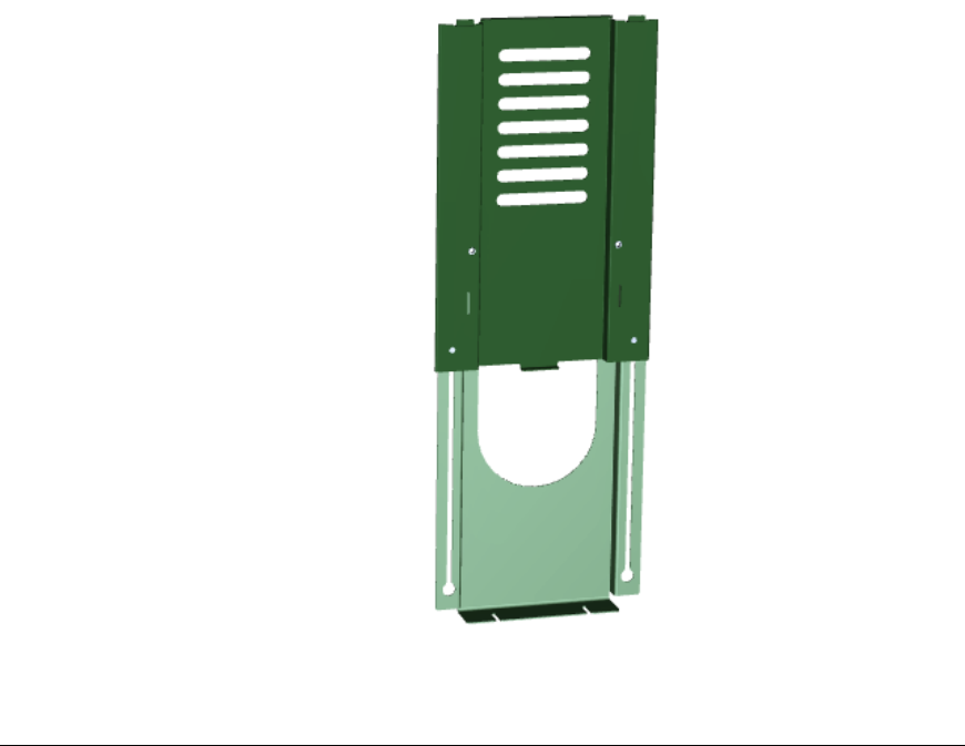
Edge Control Node 7000 Series Installation Guide 15
Figure 5. Extend the Pad Mounting Bracket
Attach Pad Mounting Bracket to Lifting Nut
Because it is generally inadvisable to drill holes into the transformer housing,
you use one of the 1.6 cm (5/8 inch) welded lifting nuts (inside the transformer
cabinet and exposed through a hole in the transformer casing) as the installation
point.
Locate one of the transformer’s lifting nuts. There is no standard for the location
of the lifting nuts, but typically one is within a few centimeters (an inch or two) of
the top of the transformer.
Measure the distance from the lifting nut to the top of the transformer, and
extend the Pad Mounting Bracket to ensure that after the bracket is attached to
the lifting nut, the top of the bracket is as close to the top of the transformer as
possible.
To secure the ECN to the transformer’s lifting nut, temporarily remove the nut.
Position the Pad Mounting Bracket so that one of the horizontal slots matches
the position of the lifting nut. Attach the Pad Mounting Bracket to the lifting
nut. Figure 6 on page 16 shows the Pad Mounting Bracket attached to the lifting
nut.
After you secure the Pad Mounting Bracket to the lifting nut, secure the bracket
to the transformer pad using the two 1.6 mm (5/8 inch) slots at the bottom of the
bracket.

16 Pad Mount Installation
Figure 6. Attach the Mounting Bracket to the Transformer’s Lifting Nut
Attach Conduit Housing to Pad Mounting Bracket
To protect the electrical and network connections to the ECN, the Pad Mounting
Bracket includes a Conduit Housing. The Conduit Housing is approximately 13
cm (5 inches) high and 30 cm (12 inches) wide. Attach the Conduit Housing to
the bottom of the upper extension of the Pad Mounting Bracket, as shown in
Figure 7 on page 17. You can perform this step prior to field installation.
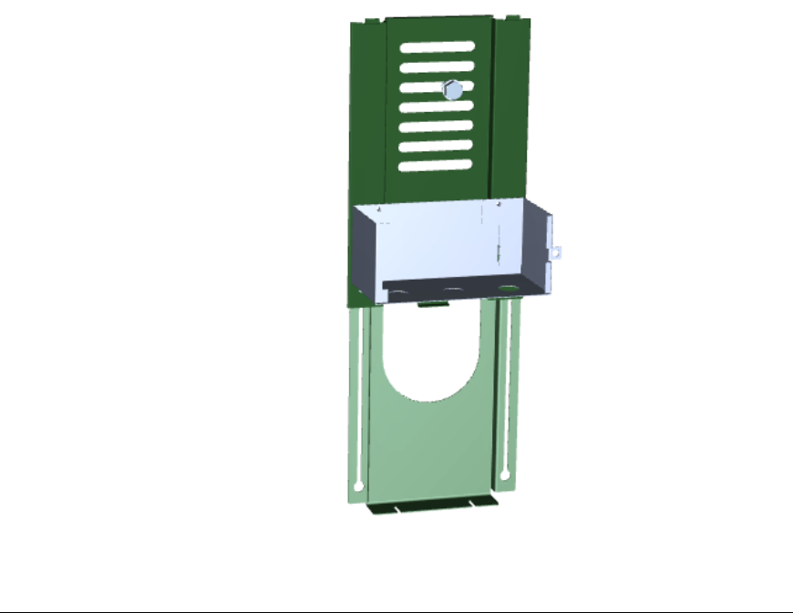
Edge Control Node 7000 Series Installation Guide 17
Figure 7. Attach the Conduit Housing to the Pad Mounting Bracket
Insert Conduit Thread into Conduit Housing
To protect the electrical and network cabling as it enters the Pad Mounting
Bracket Conduit Housing, insert a Conduit Thread unit into one of the available
holes in the bottom of the Conduit Housing. The Conduit Thread should
accommodate the locking nut for the conduit and the radius of one or more cable
bundles. The Conduit Housing provides three cutouts for conduits; at least one of
these should be precut to allow for insertion of the electrical and network cabling.
Insert the Conduit Thread into the Conduit Housing, as shown in Figure 8 on
page 18. You can perform this step prior to field installation.
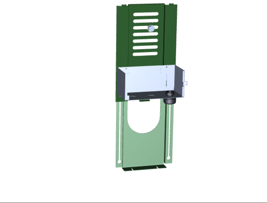
18 Pad Mount Installation
Figure 8. Insert a Conduit Thread into the Conduit Housing
Attach ECN to Pad Mounting Bracket
After the Pad Mounting Bracket is securely attached to the transformer, and the
Conduit Housing is securely in place, you can attach the ECN to the Pad
Mounting Bracket. The top of the back side of the ECN includes two tabs that
slide into the top of the Pad Mounting Bracket. Figure 9 on page 19 shows the
ECN attached to the Pad Mounting Bracket.
Note that if you should need to replace an ECN, you need replace only the ECN
and not the Pad Mounting Bracket.
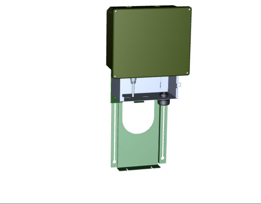
Edge Control Node 7000 Series Installation Guide 19
Figure 9. Attach the ECN to the Pad Mounting Bracket
Secure ECN to Pad Mounting Bracket
To secure the ECN to the Pad Mounting Bracket, insert two screws to the bottom
of the ECN to attach it to the Pad Mounting Bracket. These screws are already
connected to the ECN, and are designed not to make contact with the
transformer. Figure 10 on page 20 shows a front view of the ECN attached to the
Pad Mounting Bracket, with the bottom screws visible.
20 Pad Mount Installation
Figure 10. Secure the ECN to the Pad Mounting Bracket
Connect the ECN to Power and the Network
You make the connections to power and to the communications network at the
bottom of the ECN, which is inside the Conduit Housing. Figure 11 on page 21
shows the bottom of the ECN, before installation.
You can connect the ECN to either low voltage or medium voltage.
The exact configuration of the ECN bottom panel depends on the options that you
have installed in the ECN, but at a minimum, the bottom panel has a connection
for power and for at least one communications network. In the figure, the bottom
left connection is for power.
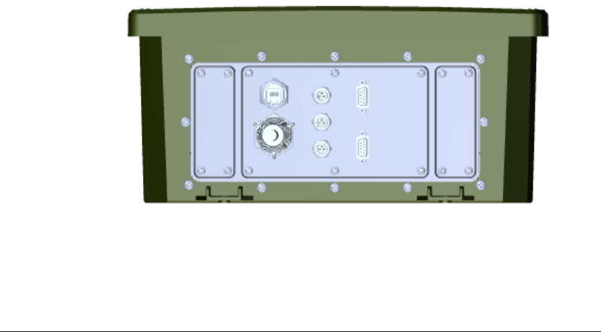
Edge Control Node 7000 Series Installation Guide 21
Figure 11. Connect the ECN to Power and the Network
Because the transformer’s lifting nut is not necessarily centered vertically with
where you placed the 1.9 cm or 3.2 cm (¾” or 1-1/4”) flexible conduit relative to
the transformer pad, ensure that the flexible conduit is long enough to reach both
the Conduit Housing and the connections on the ECN.
Close and Lock the Conduit Housing
After you have completed all cabling connections and are ready to complete ECN
installation, close the Conduit Housing door and secure it with a lock, as shown
in Figure 12 on page 22. The Conduit Housing includes a 1.3 cm (½ inch) hasp
hole for the lock.
22 Pad Mount Installation
Figure 12. Close and Lock the Conduit Housing
Complete the Installation
After the installation is complete, perform the following tasks:
1. Inspect the connection of the ECN to the Pad Mounting Bracket.
2. Inspect the connection of the Pad Mounting Bracket to the transformer.
3. Inspect the cabling connections to the ECN.
4. Inspect the transformer pad.
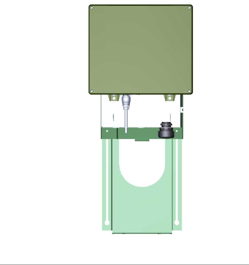
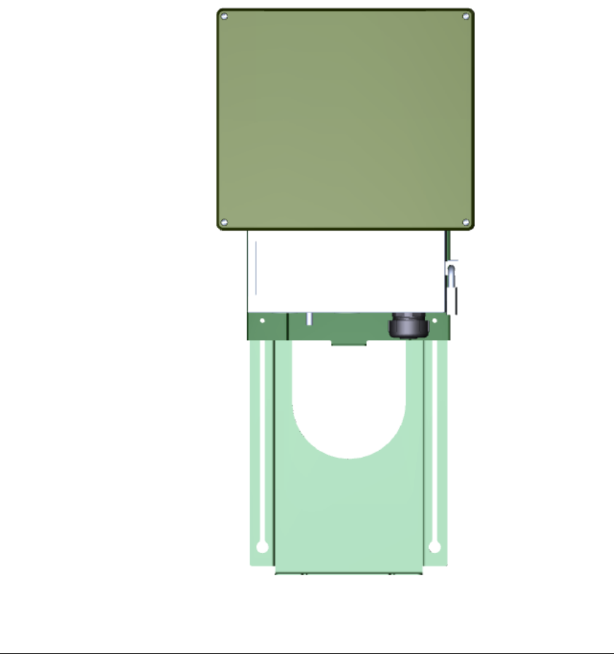
The completed installation should look similar to the views depicted in Figure 13
and Figure 14 on page 23. Note that the figures do not show the cabling
connections to the ECN.
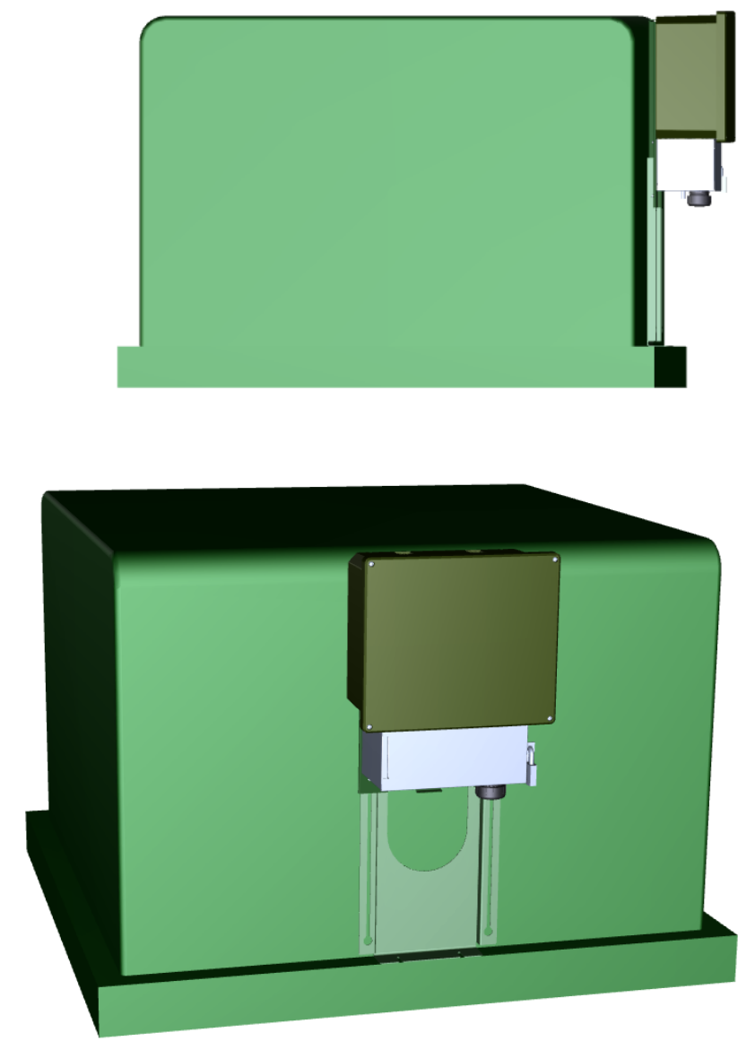
Edge Control Node 7000 Series Installation Guide 23
Figure 13. Complete ECN Installation, Viewed from the Left
Figure 14. Complete ECN Installation, Viewed from the Front

24 Pad Mount Installation
Verifying Successful Installation
Because the ECN has no external lights or displays, it uses an internal audio
buzzer to provide indications of important installation-related states. The
buzzer’s audio frequency is 2.4 kHz (as a 1/2 duty cycle square wave) and outputs
85 to 92 dBA of sound pressure,3 which should be audible from at least 10 m (30
ft). Table 2 lists the sound patterns for the audio indicator. The audio indicator
outputs its audio indicator patterns once only.
Table 2. Internal Audio Indicator Sound Patterns
Sound Pattern
On (ms) Off (ms) Repeat Description
1000 0 1 ECN first starts up
1000 0 1 ECN main processor starts running
1000 500 3 Successful direct WAN connection
1000 500 6 Successful indirect WAN connection
4000 500 2 No WAN connection made
As the table shows, a successful installation should include two 1 second sound
bursts and at least one repeated pattern (1 s on, 0.5 s off) to indicate a successful
network connection. If you receive the repeated pattern (4 s on, 0.5 s off) that
indicates unsuccessful network connection, check the network cable connection
and verify that the network is operational.
After installation is verified successful, use the ECoS Web page interface for the
ECN to verify additional functionality. You might also want to disable the
internal audio indicator so that subsequent resets or power events do not cause
the audio indicator to output its audio indicator patterns.
3 dBA measures sound pressure levels relative to 20 μPa (rms) at 1 m.
Edge Control Node 7000 Series Installation Guide 25
4
Field Replacement for an ECN
7000 Series Device
This chapter describes how to replace an ECN or an ECN’s
battery pack after the ECN has been installed in the field.

26 Field Replacement for an ECN 7000 Series Device
Overview
The ECN 7000 Series of products is designed to allow you to easily replace an
ECN unit in the field after installation. For ECN units with the backup battery
option, you can also easily replace the battery in the field.
Although an ECN is designed for a 10 year operational life, because an ECN is
typically installed in a location that exposes it to weather and other hazards, you
might need to replace ECN units from time to time. In addition, you might want
to replace a working unit with one that includes additional or different expansion
cards to provide additional services for your customers.
Because the ECN’s cover is not designed to be removed in the field (the cover is
secured with one-way screws), you generally cannot perform in-field service for
an ECN. If an ECN becomes non-operational, you should replace it in the field
with a similarly equipped model to maintain operational service for your
customers. You can return the non-operational ECN to your service center for
maintenance; see the
Edge Control Node 7000 Series Hardware Guide
for
additional information about performing service.
Replacing a Pole-Mounted ECN
Important: Before replacing an ECN in the field, visually inspect the unit and its
surroundings to ensure that the unit is not damaged and that it is safe to handle.
You do not need to reinstall the Pole Mounting Bracket to replace an ECN unit.
To remove a pole-mounted ECN:
1. If possible, use the ECoS system software to shut down the unit
remotely, before beginning field replacement.
2. Remove all network connections from the bottom of the unit.
3. Remove the power connection from the unit.
4. Remove the screws at the bottom of the unit. These screws will remain
attached to the ECN.
5. Lift the ECN from the Pole Mounting Bracket.
6. Attach a rope to the ECN carry loop to safely transport it to the ground.
To install a replacement pole-mounted ECN:
1. Attach the ECN to the Pole Mounting Bracket, as described in
Attach
ECN to Pole Mounting Bracket
on page 6.
2. Secure the ECN to the Pole Mounting Bracket using the screws at the
bottom of the unit, as described in
Secure ECN to Pole Mounting Bracket
on page 7.
3. Connect the ECN to power and to the network, as described in
Connect
the ECN to Power and the Network
on page 8.
4. Verify successful installation, as described in
Verifying Successful
Installation
on page 9.

Edge Control Node 7000 Series Installation Guide 27
Replacing a Pad-Mounted ECN
Important: Before replacing an ECN in the field, visually inspect the unit and its
surroundings to ensure that the unit is not damaged and that it is safe to handle.
You do not need to reinstall the Pad Mounting Bracket to replace an ECN unit.
To remove a pad-mounted ECN:
1. If possible, use the ECoS system software to shut down the unit
remotely, before beginning field replacement.
2. Unlock the Conduit Housing and open the Conduit Housing door.
3. Remove all network connections from the bottom of the unit.
4. Remove the power connection from the unit.
5. Remove the screws at the bottom of the unit. These screws will remain
attached to the ECN.
6. Lift the ECN from the Pad Mounting Bracket.
To install a replacement pad-mounted ECN:
1. Attach the ECN to the Pad Mounting Bracket, as described in
Attach
ECN to Pad Mounting Bracket
on page 18.
2. Secure the ECN to the Pad Mounting Bracket using the screws at the
bottom of the unit, as described in
Secure ECN to Pad Mounting Bracket
on page 19.
3. Connect the ECN to power and to the network, as described in
Connect
the ECN to Power and the Network
on page 20.
4. Close the Conduit Housing and lock the door, as described in
Close and
Lock the Conduit Housing
on page 21.
5. Verify successful installation, as described in
Verifying Successful
Installation
on page 24.
Replacing the Battery Pack
To allow the ECN to run continuously, regardless of external power conditions,
the ECN includes a backup battery option. If your ECN includes this option, you
will occasionally need to replace the batteries.
The battery packs are located in their own dedicated compartment accessible
from the outside of the ECN enclosure, as shown in Figure 15 on page 28. Within
this compartment, an electrical connector on a flying lead allows easy installation
of each battery pack. This separate compartment is weather tight and provides
shielding from sensitive electronics and transceivers.
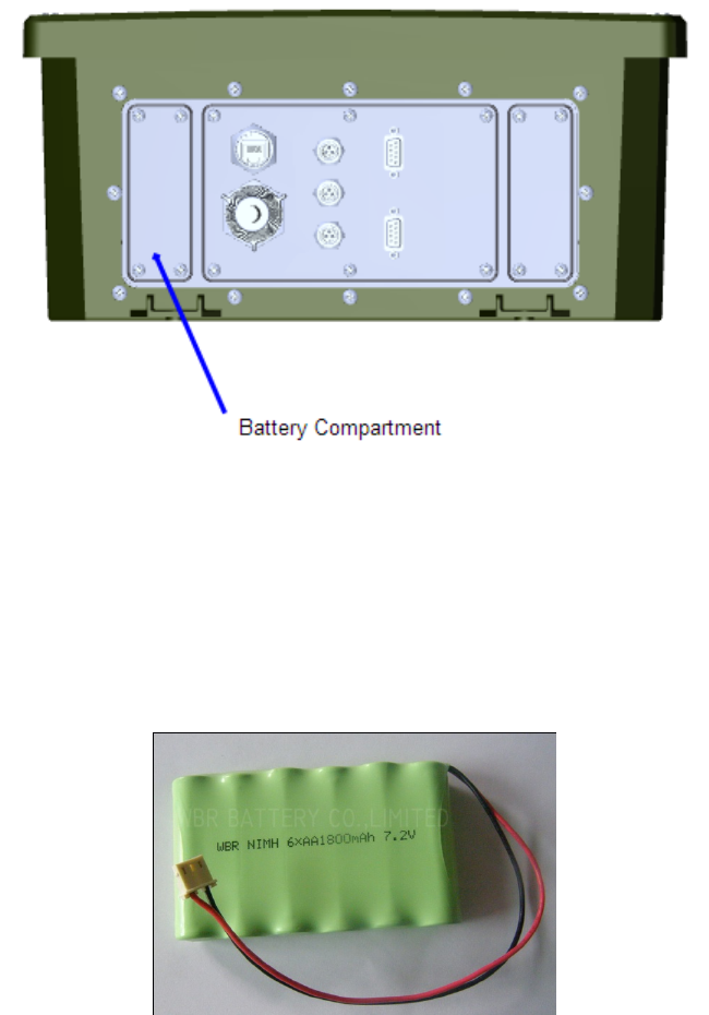
28 Field Replacement for an ECN 7000 Series Device
Figure 15. ECN Battery Compartment Location
The ECN uses intelligent battery charging techniques to maximize the life of the
battery. That is, the ECN occasionally discharges and recharges the battery to
maintain battery capacity and prolong its life. A typical discharge/charge cycle
can take up to 16 hours. During this time, the ECN could be vulnerable to power
loss during the discharge cycle, so you should use dual battery packs. Each pack
can be independently charged on alternating cycles so that a fully charged
battery pack is always available. Each battery pack has an operating life of
approximately 10 years. Figure 16 shows a typical battery pack.
Figure 16. Typical Battery Pack
Each battery pack is comprised of six AA size (IEC HR6 / ANSI 1.2H2) batteries
to provide 1800 mAh or 2200 mAh at 7.2 V with 12 cm (5 inch) connection leads.
Table 3 on page 29 lists specifications for the battery pack.

Edge Control Node 7000 Series Installation Guide 29
Table 3. Battery Pack Specifications
Specifications Dimensions and Weight
Size: 6 AA Cells
Configuration: Side by side
Capacity: 1800 mAh or 2200 mAh
Chemistry: NiMH
Voltage: 7.2 V
Length: 85 mm (3.38”)
Height: 14 mm (0.56”)
Weight: 226 g (8 oz)
Edge Control Node 7000 Series Installation Guide 31
A
ECN 7000 Series Specifications
This appendix lists the specifications for the ECN 7000
Series of products.

32 ECN 7000 Series Specifications
General Specifications
Table 4 summarizes the general specifications for ECN 7620 and 7650 devices.
Table 4. General Specifications
Category Rating
Input Voltage:
Single Phase
Three Phase
3-wire 120/240 V ±20% 60 Hz ±2%
3- or 4-wire 230/277 V ±20% 50/60 Hz ±2%
Battery Power Input (Optional)
Battery backup module (15 minutes)
Uninterruptible Power Supply (UPS) interface module
(input 12 V or 24 V)
??Maximum Devices Managed ??Up to 1024 NES electricity meters and 4096 associated
M-Bus devices, depending upon the model purchased.
??Program Storage ??Non-volatile memory
Power Consumption 5 W typical
30 W maximum
??Phase Coupling ??Connections for 3 phases (L1Ø, L2Ø, L3Ø) and Neutral.
??Indicators
??Blue power LED (illuminates when both AC power
mains are present on the Neutral and any phase and the
power supply is functioning correctly)
Dimensions
7650 H: 305 mm – W: 356 mm – D: 178 mm
(H: 12” – W:14” – D: 7”)
7620 H: 280 mm – W: 288mm – D: 141mm
(H: 11” – W: 11.5” – D: 5.5”)
Weight <5.4 kg
(<12 lb)
Enclosure 7650 UV stable plastic (grey or green); rated NEMA4/IP67
7620 Plastic (grey); rated IP54
Mounting
7650 Separate mounting kit
7620 DIN 43857mount; four screw holes to accommodate 5
mm screws for direct wall mount

Edge Control Node 7000 Series Installation Guide 33
Category Rating
Security
Impact- and vandal-resistant plastic
High-security screws
Tamper detection (operates whether powered or
unpowered)
Optional tilt detector
??Serial Number Indication ??Text and barcode
??Clock ??Real-time clock accurate to ±1 minute per month;
corrected by NES System Software.
Environmental Rating Specifications
Table 5 summarizes the environmental rating specifications for ECN 7620 and
7650 devices.
Table 5. Environmental Rating Specifications
Category Rating
Operating Temperature Range
-40 °C to +70 °C (-40 °F to +158 °F)
Certain options (for example, radios) could have additional
limits.
ANSI C12.1 2008 4.7.3.16 168hrs -40C to +70C
??IEC 62052-11: -25oC to 55oC
??Limited Operating
Temperature Range ??IEC 62052-11: -40oC to 70oC
Storage Temperature Range
-40 °C to +85 °C (-40 °F to +185 °F)
ANSI C12.1 2008 4.7.3.15 168hrs -40oC to +85oC
??IEC 62052-11: -40oC to 70oC
Effective Relative Humidity
??Operating Humidity
(non-condensing)
0% to 95%, non-condensing
As per ANSI C12.1 2008
ANSI C12.1 2008 4.7.3.22 in accordance with ASTM G155
??IEC 62052-11: 25-90% @ 50o C
Weather Simulation Test
??Storage Humidity
(non-condensing)
ANSI C12.1 2008 4.7.3.22 in accordance with ASTM G155
??IEC 62052-11: 95% RH @ 50o C

34 ECN 7000 Series Specifications
Category Rating
Salt Spray Test
??Dry Heat
ANSI C12.1 2008 4.7.3.23 in accordance with ASTM B117
??IEC 60068-2-2; 70o C, 72 hours
Raintightness
??Cold
NEMA 4 and ANSI C12.1 2008 4.7.3.24 in accordance with
UL 50 E
??IEC 60068-2-1; -40o C, 16 hours
??Damp Heat Cyclic ??IEC 60068-2-30: 25o C - 55o C @ 95% humidity for 6 days
??Change of Temperature ??IEC 60068-2-14: 70o C to -25o C in 6 hours
Solar Radiation As per ANSI C12.1 2008
Salt Fog As per ANSI C12.1 2008
Mechanical Specifications
Table 6 summarizes the mechanical specifications for ECN 7620 and 7650
devices.
Table 6. Mechanical Specifications
Category Rating
General Mechanical
Requirements IEC 60068-2-11
Mechanical Tests:
Mechanical Shock
??Spring Hammer
ANSI C12.1 2008 4.7.3.18 in accordance with IEC 60068-2-
27
??IEC 60068-2-75: .2 Joules kinetic energy
Transportation Drop
??Shock
ANSI C12.1 2008 4.7.3.19 in accordance with ISTA
procedure 1A
As per ANSI C12.1 2008
??IEC 60068-2-27: 30g, half-sine, 18ms
Mechanical Vibration
??Vibration
ANSI C12.1 2008 4.7.3.20 in accordance with IEC 60068-2-
6
As per ANSI C12.1 2008
??IEC 60068-2-6: 10-150 Hz, 0.075mm/1g @ 1 octave per
minute. 10 cycles

Edge Control Node 7000 Series Installation Guide 35
Category Rating
Transportation Vibration ANSI C12.1 2008 4.7.3.21 in accordance with ISTA
procedure 1A
Resistance to Heat and Fire IEC 60695-2-11
Mechanical Wind Shear Can withstand a 190 Pa (4 lb/sq-ft) wind simultaneously
with (12 mm) ½” thick ice
Electrical Specifications
Table 7 summarizes the electrical specifications for ECN 7620 and 7650 devices.
Table 7. Electrical Specifications
Category Rating
Specified Operating Range 240 VAC ± 20%
??IEC 62052(7.1.1): - 0.8 to 1.1 Un
Insulation Resistance ANSI C12.1 2008 4.7.3.1 2.5kV for 1 minute
??IEC 62052(7.1.1): - 0.0 to 1.15 Un
Voltage Interruptions ANSI C12.1 2008 4.7.3.2
??IEC 61000-4-11: 30%, 50%, 60%, 100% and +12% to -15%
High Voltage Surge
ANSI C12.1 2008 4.7.3.3.1 100kHz Ring Wave in
accordance with ANSI C62.41 (Category B)
ANSI C12.1 2008 4.7.3.3.2 Combination Wave in
accordance with ANSI C62.41 (Category B)
??IEC 62053-21 (7.4)
Effect of Current Surge in
Ground Conductor
ANSI C12.1 2008 4.7.3.7
??IEC 62052-11 (7.3)
Safety Specifications
Table 8 summarizes the safety specifications for ECN 7620 and 7650 devices.
Table 8. Safety Specifications
Category Rating

36 ECN 7000 Series Specifications
Category Rating
Safety
UL 60950, EN 60950, CSA 60960
CE Marking
RoHS-compliant
??Safety Rating
??Certified by TÜV, Semko, and KEMA-KEUR per EN-
60950; CE Marked; UL60950, and CSA60950 by TÜV
under NRTL
EMC Specifications
Table 9 summarizes the electromagnetic compatibility (EMC) specifications for
ECN 7620 and 7650 devices.
Table 9. EMC Specifications
Category Rating
Immunity to Electrostatic Discharge:
Contact Discharge IEC 62052-11 (7.5.2), IEC 61000-4-2: 8 kV
Air Discharge IEC 62052-11 (7.5.2), IEC 61000-4-2: 15 kV
Immunity to Electromagnetic
RF Fields (80MHz to 2000
MHz)
IEC 62052-11 (7.5.3), IEC 61000-4-3: 30 V/m
Fast Transient Burst IEC 62052-11 (7.5.4), IEC 61000-4-4: 4 kV common mode
Immunity to Conducted Disturbances:
150 kHz to 80 MHz IEC 62052-11 (7.5.5), IEC 61000-4-6: 10 Vrms
Surge Immunity IEC 62052-11 (7.5.6), IEC 61000-4-5: 6 kV common mode,
4 kV differential mode
Power frequency magnetic field IEC 61000-4-8, IEC 61000-4-12, IEC-61000-4-13, IEC
61000-4-16: 1000 A/m
Radiated Emissions EN 55022 – Class B
Conducted Emissions with PLC EN 50065-1 – Class B

Edge Control Node 7000 Series Installation Guide 37
FCC Specifications
TBD
Communications Specifications
Table 10 summarizes the communications specifications for ECN 7620 and 7650
devices.
Table 10. Communications Specifications
Category Rating
Power line Network LV CENELEC 50065-1 Line Communication (PLC)
LV 150/IEC 14908-3 PLC (CENELEC 50065 C-Band)
Wide Area Network
Ethernet
Dual-band 3G CDMA (EV-DO) with main and diversity
antenna (North America)
Quad-band GPRS (GSM) (worldwide)
Local Networks (optional)
ISO/IEC 14908-2 Twisted Pair Communication
Ethernet
High-power 2.4/5GHz IEEE 802.11b/g/n access point and
neighborhood-area intercommunication network (supports
IEEE 802.11i and IEEE 802.11s (draft))
??Data Security
??CHAP, MS-CHAP, PAP and 128-bit application-level
authentication for WAN; 96-bit authentication on power
line network; 128-bit RC4 encryption for WAN and power
line communication; Password protection for optical
communication
External Connection Specifications
Table 11 summarizes the external connection specifications for ECN 7620 and
7650 devices.
Table 11. External Connection Specifications
Category Rating

38 ECN 7000 Series Specifications
Category Rating
??AC Power Mains Input
??The three-phase AC input power connection serves two
purposes:
(a) AC input power for the Data Concentrator is provided
from the Neutral and any phase.
(b) LONWORKS power line channel signaling using three-
phase, Line-to-Neutral coupling.
EIA-232 Serial Ports
EIA-232C serial port protocol operating up to 115.2 kbps
per second when used with a Hayes-compatible cellular
(CSD/CDMA/GPRS) or landline modem. Optionally, 9.6
kbps in direct serial connection (null-modem) mode.
All modes operate with 8 data bits, 1 stop bit and no
parity.
Configured as DTE (Data Terminal Equipment).
Optional Three-Phase Current
Transformer (CT) Inputs LV or MV, 0.333 V standard, include external connectors
Optional LEDs Indicate operational and connectivity status
Optional Digital Inputs Include external connectors
Optional Temperature Input Includes external connector
Optional GPS Receiver Active antenna, 12 channel
Expansion Slot Type A
Accommodates up to four 129 mm x 91 mm (5.07” x 3.58”)
expansion cards. Each expansion slot includes card
guides, USB data, and power interconnect with +3 VDC to
+12 VDC variable voltage input determined by expansion
card, 3 W average power dissipation.
Expansion Slot Type B
Accommodates one expansion card of up to 144 mm x 107
mm x 40 mm (5.67” x 4.21” x 1.57”). Designed for
expansion cards that do not conform to the Type A
expansion card format. USB power and data interconnect
support included in the slot area; up to two antenna
connections supported.
Expansion Slot Type C
Accommodates one expansion card of up to 204 mm x 151
mm x 15 mm (8.03” x 5.94” x 0.59”). Designed for
expansion cards that do not conform to the Type A
expansion card format. USB power and data interconnect,
Ethernet, supported; up to four antenna connections
supported.

Edge Control Node 7000 Series Installation Guide 39
Category Rating
??Infrared Port
??EN 61107 mode C optical communications physical and
electrical interface operating at direct-connect speeds up to
9.6 kbps.
??A ferrous metal ring is integrated into the optical
connection socket for use with a compatible, magnetically-
coupled infrared reading head.
Life Expectancy
Table 12 summarizes the life expectancy specifications for ECN 7620 and 7650
devices.
Table 12. Life Expectancy Specifications
Category Rating
Life Expectancy
The Data Concentrator has been designed for a life
expectancy of at least 10 years, at annual average ambient
temperatures less than or equal to 35 °C and greater than
or equal to -40 °C.
??MTBF
??The predicted mean time between failures (MTBF),
based on MIL-217F Notice 2 with realistic modifications at
25°C, is approximately 2,324,908 hours for DC-1000/SL
Data Concentrators and 1,785,714 hours for DC-1000/SLE
Data Concentrators.
??These MIL calculations are very conservative. DC-
1000/SL and DC-1000/SLE Data Concentrators have been
designed such that the failure rate for 20 years at an
annual average ambient temperature of up to 25°C will
not exceed 0.3% failures per year.
Edge Control Node 7000 Series Installation Guide 41
B
Safety and High-Voltage Warnings
This appendix provides the safety and high-voltage
warnings for the ECN 7000 Series of products.

42 Safety and High-Voltage Warnings
Safety and High-Voltage Warning
Safety and High Voltage Warning
Ensure that the AC input power is turned OFF before removing the front cover,
handling the input power wiring, or connecting any input power cabling to the
ECN 7620 or 7650.
The ECN 7620 or 7650 is not equipped with a power disconnect device. When the
ECN 7620 or 7650 is installed and mounted, the installer must provide a means
to safely remove power and install a circuit breaker with a maximum rating of
16A.
The high-voltage terminal block has a plastic cover protecting the screw
terminals used to connect the high-voltage inputs. This cover MUST be replaced
after the power wires are connected and before the power is activated.
DO NOT under any circumstances connect the ECN 7620 or 7650 to mains
voltages outside of the range 100 to 240VAC, -10% to +20%, 50/60Hz.
DO NOT under any circumstances connect the ECN 7620 or 7650 to a modem
whose required operating voltage is not 14 VDC (300mA maximum).
Alerta de Seguridad y Alto Voltaje
Asegúrese que la red eléctrica de corriente alterna AC este DESENERGIZADA
antes de: remover la cubierta, manipular los cables de alimentación o conectar
cualquier cableado al dispositivo ECN 7620 o 7650.
El ECN 7620 o 7650 no esta equipado con un dispositivo de desconexión de
energía. Cuando el dispositivo está instalado y montado, el instalador debe
proporcionar medios para remover la energía de manera segura e instalar un
interruptor de energía con un valor nominal máximo de 16 A.
Bajo NINGUNA circunstancia opere el dispositivo ECN 7620 o 7650 en redes
eléctricas con voltajes fuera del rango 100 to 240VAC, -10% to +20%, 50/60Hz.
Bajo NINGUNA circunstancia conecte el dispositivo ECN 7620 o 7650 a un
módem cuyo voltaje de funcionamiento esté fuera del rango 14 VDC @ 300mA.
Sécurité et Avertissement Haute Tension
Assurez vous que l’interrupteur Marche Arrêt est dans la position Arrêt avant
d’enlever le capot ou de manipuler les câbles d’alimentation, ou bien quand vous
branchez un cordon secteur au ECN 7620 ou 7650.
L’ ECN 7620 ou 7650 ne possède pas d’interrupteur pour son alimentation. Une
fois l’ ECN 7620 ou 7650 monté, l’installateur doit fournir un moyen de couper
cette alimentation de manière sécurisée et d’installer un interrupteur externe
d’un valeur maximale de 16A.
Edge Control Node 7000 Series Installation Guide 43
Le bloc terminal haute tension possède un couvercle plastique pour protéger le
bornier à vis recevant la puissance. Ce couvercle DOIT être replacé correctement
à son emplacement d’origine une fois les câbles vissés et avant que la puissance
ne soit activée.
Il ne faut JAMAIS connecter l’ ECN 7620 ou 7650 à une tension d’alimentation
hors de la plage 100 to 240VAC, -10% to +20%, 50/60Hz.
L’ ECN 7620 ou 7650 ne possède pas d’interrupteur pour son alimentation. Une
fois l’équipement monté, l’installateur doit fournir un moyen de couper cette
alimentation de manière sécurisée avec un interrupteur externe.
Sicherheitshinweis: Vorsicht Hochspannung
Schalten Sie die Stromversorgung AUS bevor Sie den Gehäusedeckel entfernen,
die Stromführenden Kabel berühren, oder jegliche Netzverbindung mit dem
Gerät ECN 7620 oder 7650 hergestellt wird.
Der ECN 7620 oder 7650 besitzt keinen eigenständigen
Stromunterbrechungsmechanismus. Bei der Installation muss der Installateur
für eine sichere Möglichkeit der Stromunterbrechung sorgen und einen
Sicherungsautomaten mit einen Höchstnennstrom von 16 A anbringen.
Die Klemmenleiste besitzt eine Plastik Haube und schützt die Schrauben die
zum Anschluss der Hochspannung dienen. Diese Haube MUSS wieder
angebracht werde, nachdem die Stromkabel angeschlossen und bevor die
Stromzuführung wieder freigeschaltet wurde.
Unter KEINEN UMSTÄNDEN darf das Gerät ECN 7620 oder 7650 mit einer
Eingangsspannung außerhalb des Bereichs 100 to 240VAC, -10% to +20%,
50/60Hz betrieben werden.
Unter KEINEN UMSTÄNDEN darf das Gerät ECN 7620 oder 7650 an ein
Modem angeschlossen werden, dessen vorgeschriebene Betriebsspannung
außerhalb folgender Bereiche 14 VDC @ 300mA.
Säkerhets- och högspänningsvarning
Kontrollera att nätspänningen är FRÅN innan höljet tas bort, nätledningarna
vidrörs eller nätkablar ansluts till ECN 7620 or 7650 -enheten.
ECN 7620 eller 7650 är inte utrustad med en frånkopplingsenhet till nätet. När
datakoncentratorn installeras och monteras, måste installatören se till att det
går att stänga strömmen på ett säker sätt och montera en huvudströmbrytare
med max 16A spänning.
Kopplingsplinten till högspänningen har ett plastskydd som skyddar
skruvkontakterna som används för att ansluta ingående högspänning. Detta
skydd MÅSTE sättas tillbaka efter det att nätkablarna anslutits och innan
nätspänningen slås på.
ECN 7620 eller 7650 enheten får under inga omständigheter anslutas till
nätspänningar som inte ligger inom intervallen 100 to 240VAC, -10% to +20%,
50/60Hz.
ECN 7620 eller 7650 -enheten får under inga omständigheter anslutas till ett
modem vars driftspänning ligger utanför intervallen 14 VDC @ 300mA.

44 Safety and High-Voltage Warnings
Avvertenza sulla Sicurezza e sull’Alta Tensione
Assicurarsi che la rete elettrica sia SPENTA prima di rimuovere il coperchio,
maneggiare i cavi di alimentazione, o connettere qualsiasi cavo al ECN 7620 o
7650.
Il ECN 7620 o 7650 non viene fornito con un dispositivo di disconnessione
dell’alimentazione. Quando il concentratore viene installato e montato,
l’installatore deve predisporre un sistema per poter staccare l’alimentazione in
sicurezza e installare un interruttore del circuito con una potenza massima di
16A.
NON connettere mai per nessun motivio il ECN 7620 o 7650 a tensioni al di fuori
del range 100 to 240VAC, -10% to +20%, 50/60Hz.
NON connettere mai per nessun motivio il ECN 7620 o 7650 ad un modem la cui
alimentazione sia al di fuori del range 14 VDC @ 300mA.
Safety Warning
Safety Warning
The ECN 7620 or 7650 uses three Wickmann rated 250VAC, 10A, SLO-BLO
fuses, one per each phase.
Advertencia de Seguridad
El ECN 7620 o 7650 usa un Wickmann clasificado a 250VAC, 10A, SLO-BLO.
Avertissement Sécurité
L’ ECN 7620 ou 7650 utilise un Wickmann à 250VAC, 10A, fusion lente SLO-
BLO.
Sicherheitshinweis
Die Sicherung (Wickmann) im ECN 7620 oder 7650 ist ausgelegt für 250VAC,
10A, SLO-BLO.
Säkerhetsvarning
Säkring i ECN 7620 eller 7650 använder en nominal Wickmann 250VAC, 10A,
SLO-BLO.
Edge Control Node 7000 Series Installation Guide 45
C
ESD and Battery Warnings
This appendix provides the electrostatic discharge (ESD)
and battery warnings for the ECN 7000 Series of products.
The battery is end-user serviceable, and the ECN 7620 or
7650 device will continue to operate even if the battery fails.
46 ESD and Battery Warnings
ESD Warning
ESD Warning
This product contains components which are sensitive to static electricity. Before
installing or removing the serial cable, touch earth ground with your hand to
discharge any static electricity which may have accumulated.
Advertencia de ESD
Este producto contiene componentes que son sensibles a la electricidad estática.
Antes de instalar o de quitar el cable serial, asegurese de tocar un contacto a
tierra para descargar cualquier electricidad estática que pudiera haberse
acumulado.
Avertissement ESD
Ce produit contients des composants qui sont sensibles à l’électricité statique.
Avant de brancher ou de débrancher le cordon série, veuillez placer la main sur
la borne de terre pour évacuer toute électricité statique accumulée
Hochspannung ESD
Dieses Produkt beinhaltet Komponenten die empfindlich für eine statische
Aufladung sind. Bevor Sie serielle Kabel installieren oder entfernen, müssen Sie
für eine ordnungsgemäße Entladung der statischen Aufladung sorgen, in dem Sie
mit der Hand eine Erdungsstelle berühren.
ESD Varning
Denna produkt innehåller komponenter som är känsliga för statisk elektricitet.
Innan seriekabeln ansluts eller tas bort, vidrör markjord med handen för
urladdning av eventuell statisk elektricitet som kan ha uppstått.
Battery Warning
Battery Warning
The ECN 7620 or 7650 contains a backup battery for the real-time clock. There
is a risk of explosion if this battery is replaced with an incorrect type. Please
dispose of the used batteries in accordance with the manufacturer’s instructions.
Advertencia de la Batería
El ECN 7620 o 7650 contiene una batería de reserva. Hay un riesgo de explosión
si esta batería se substituye por una del tipo incorrecto. Disponga por favor de las
baterías usadas de acuerdo con las instrucciones del fabricante.
Edge Control Node 7000 Series Installation Guide 47
Avertissement Batterie
L’ ECN 7620 ou 7650 contient une batterie pour les sauvegardes. Il y a un risqué
d’explosion dans le cas ou cette batterie est remplacée par un modèle non
conforme. Meric d’utiliser des batteries en accord avec les instructions
constructeur.
Sicherheitshinweis: Vorsicht Batterie!
Der ECN 7620 oder 7650 enthält eine Batterie für die Echtzeituhr. Es besteht
die Gefahr einer Explosion, falls diese Batterie durch einen falschen Batterietyp
ersetzt wird. Bitte, entsorgen Sie die gebrauchten Batterien entsprechend den
Herstellerhinweisen.
Avvertenza sulla Batteria
Il ECN 7620 o 7650 contiene al suo interno una batteria di back-up per il
funzionamento del real time clock (RTC). Se la batteria viene sostituita con un
tipo non conforme, ci potrebbe essere pericolo di esplosione. Se prega di
eliminare le batterie usate in accordo con quanto specificato nelle istruzioni del
costruttore.
Batterivarning
ECN 7620 eller 7650 har ett back-up-batteri. Om batteriet byts ut mot ett
batteri av fel typ föreligger explosionsrisk. Se till att batteriet förstörs enligt
tillverkarens anvisningar.