Echelon 76530R CRD 3000 Control Router User Manual Exhibit D Users Manual per 2 1033 b3
Echelon Corporation CRD 3000 Control Router Exhibit D Users Manual per 2 1033 b3
UserManual.wiki
>
Echelon
>
76530R User Manual
Exhibit D Users Manual per 2 1033 b3
Navigation menu
Upload a User Manual
Namespaces
Wiki Guide
HTML
PDF
Info
Views
User Manual
Discussion / Help
Navigation

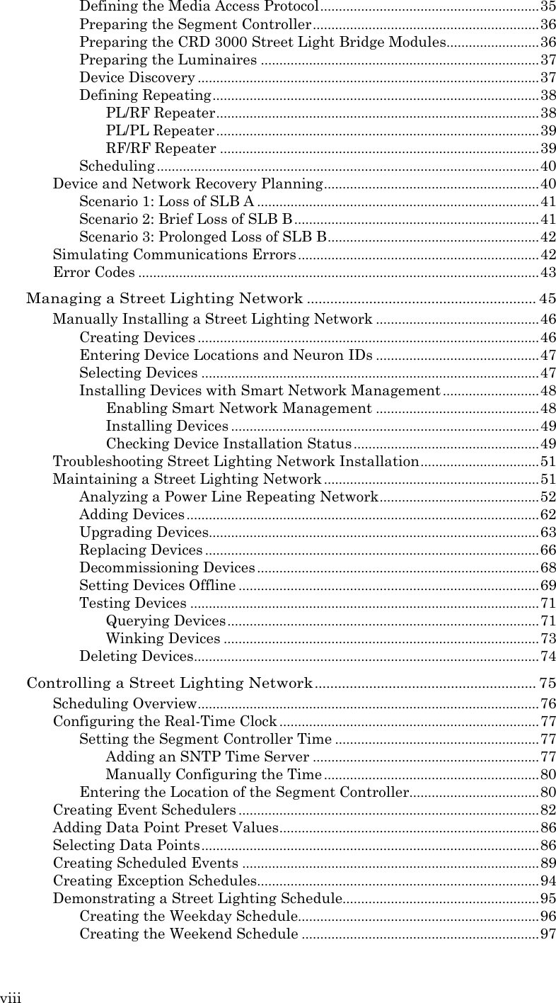
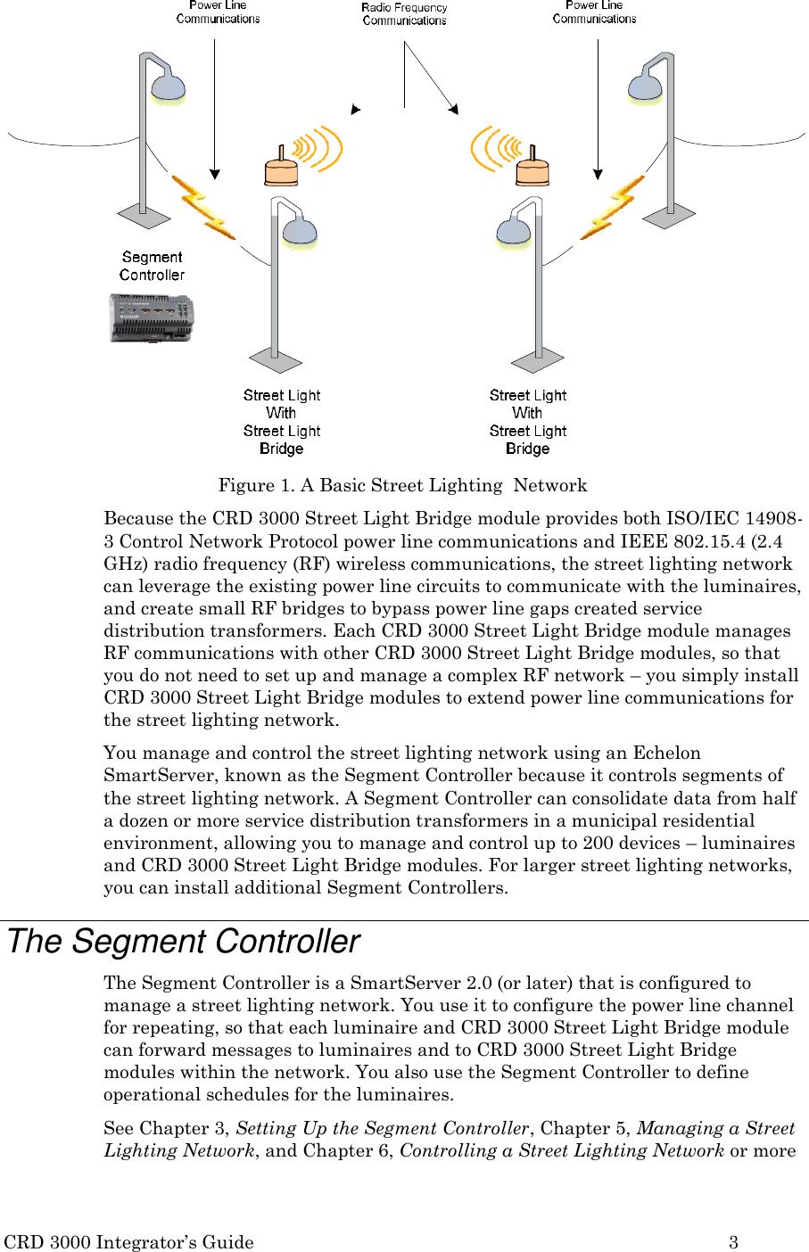
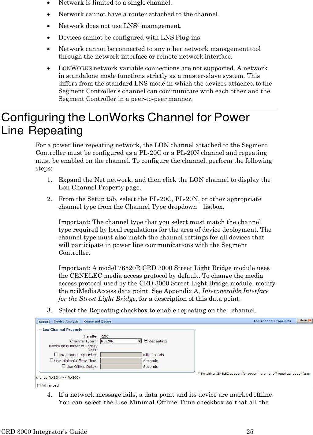
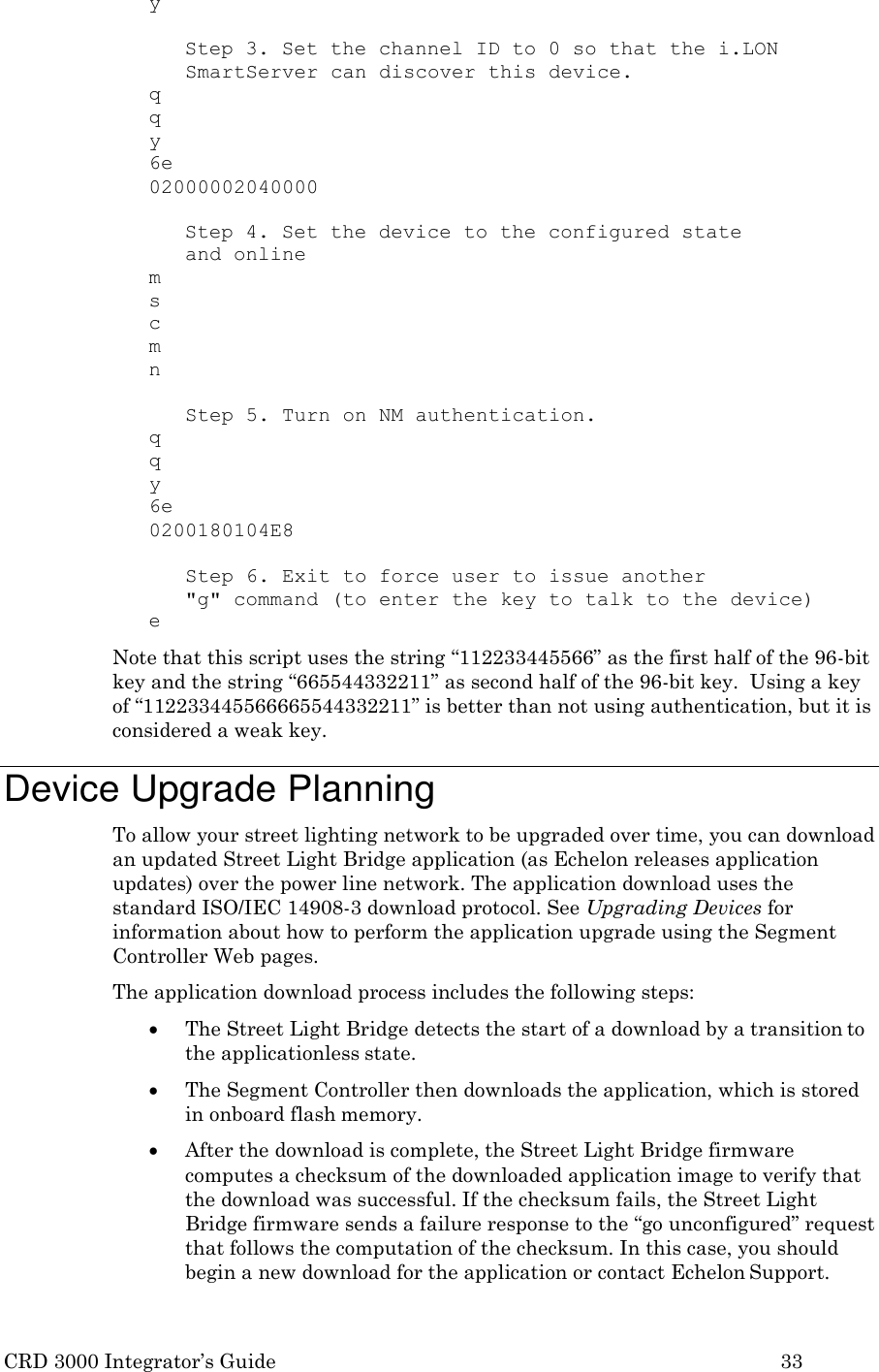
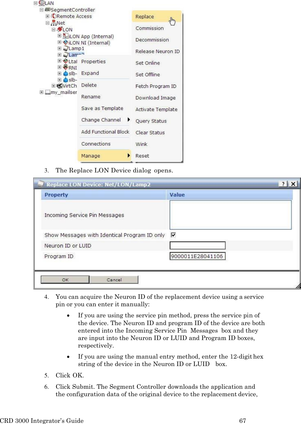
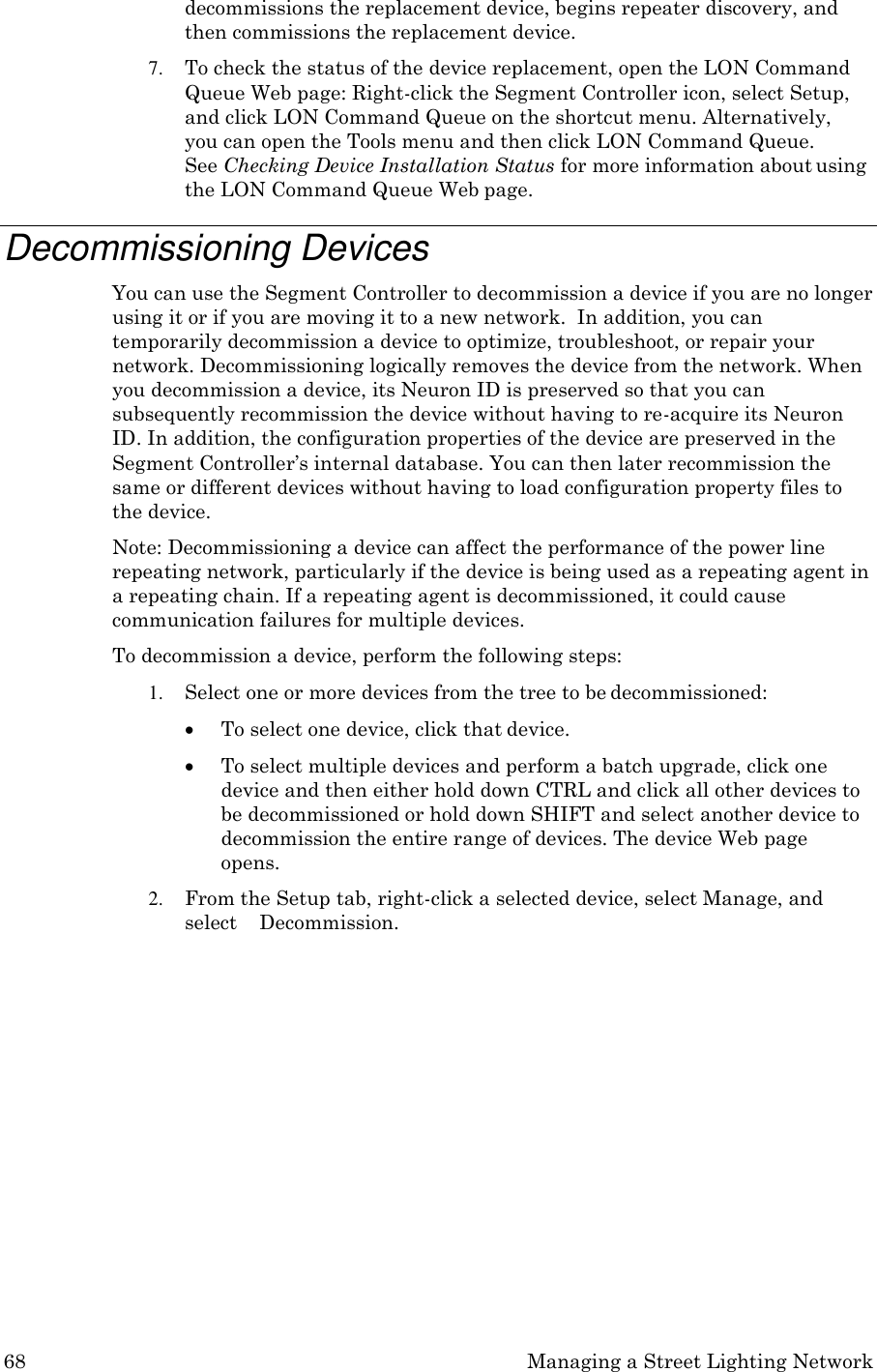
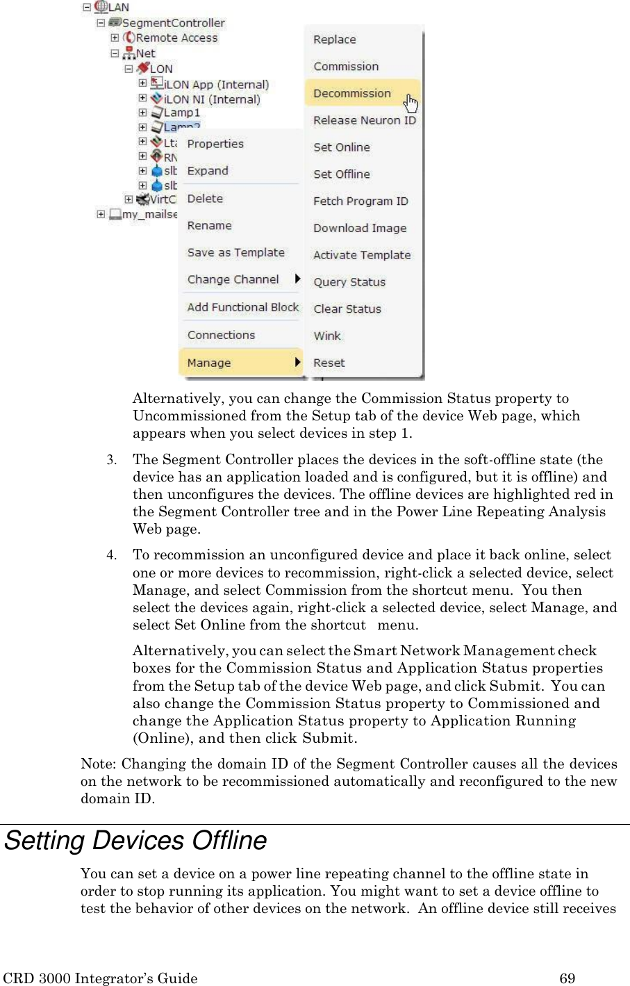
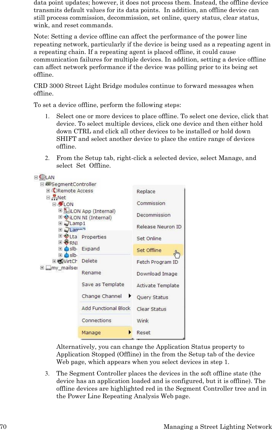
![110 Glossary A Alternate path The path specified by LTEP when the “alternate path” bit is set. C Channel An RF or PLC frequency. CQA Channel Quality Assessment – algorithm that maintains statistics for all RF channels to support FAA. D Downstream [RF] channel The channel which a device normal listens to on RF waiting for a downstream message. Downstream message A message (for example, request) going from the Segment Controller to a target device. F FAA Frequency Agility Algorithm – algorithm that chooses the best RF receive channel to ensure good RF communications. L LTEP – LonTalk Enhanced Proxy The repeating scheme used by the Segment Controller over PLC. N Normal path The path specified by LTEP when the “alternate path” bit is not set. P Path A means for getting from point A to point B which could include a specific carrier frequency, specific modulation scheme or whatever. This name is historical and not very accurate (since path would more typically be a route as opposed to mode of conveyance).](https://usermanual.wiki/Echelon/76530R/User-Guide-3484277-Page-120.png)
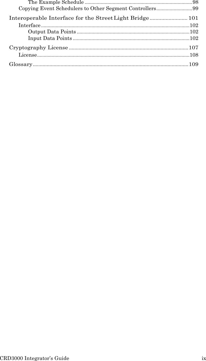
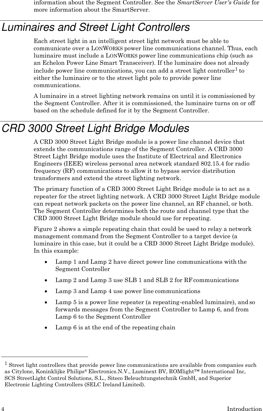
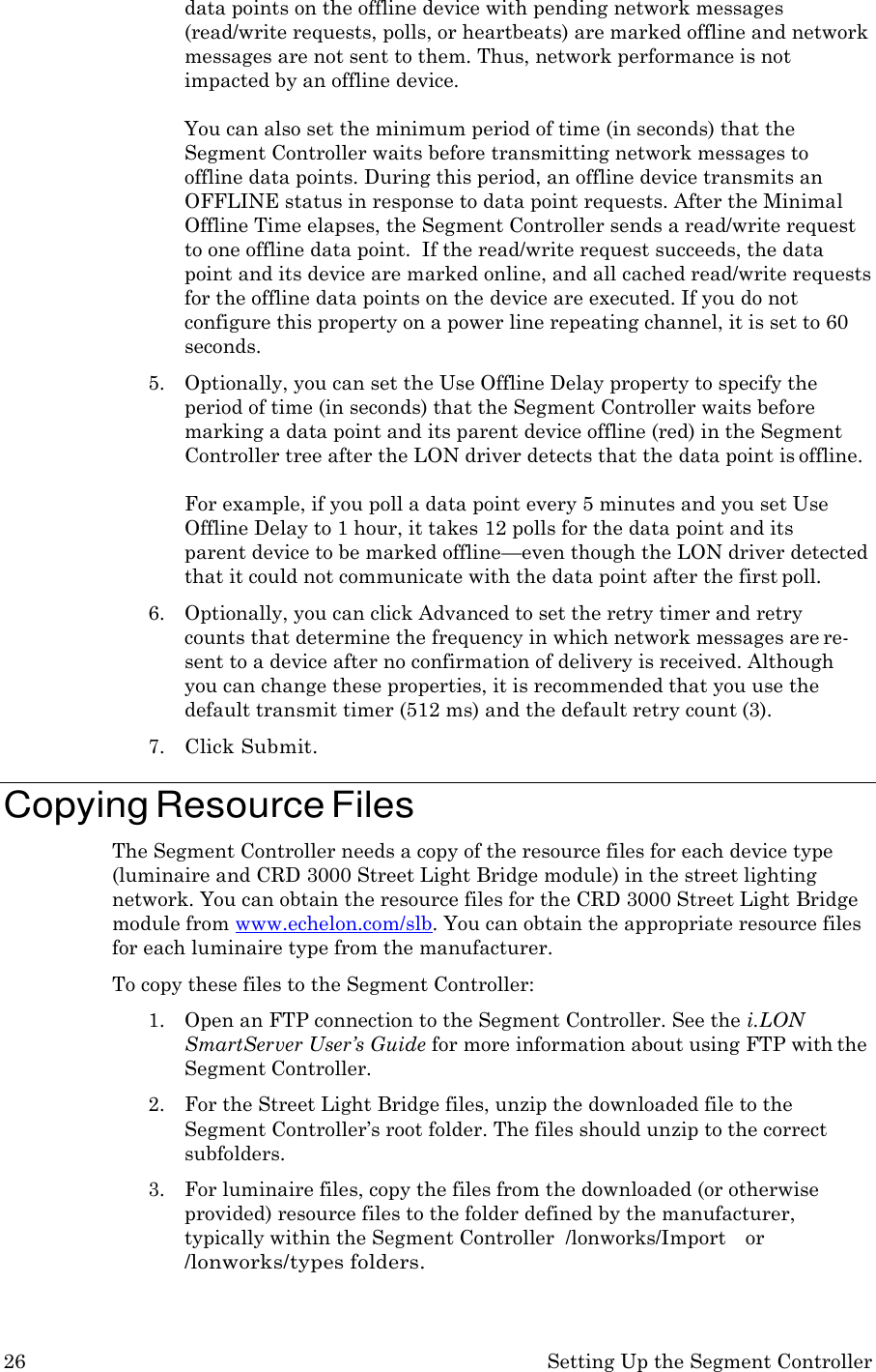
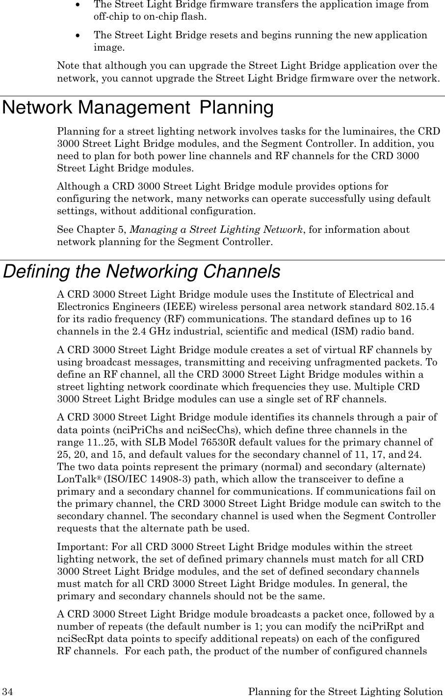
![CRD 3000 Integrator’s Guide 111 PLC Power line carrier or power line communications. Primary channels A set of channels used to transmit on when the normal path is specified by LTEP. Primary receive channel The channel a device listens to when awaiting an upstream message (for example, response) on the normal path. S Secondary channels A set of channels used to transmit on when the alternate path is specified by LTEP. Secondary receive channel The channel a device listens to when awaiting an upstream message (for example, response) on the alternate path. SLB CRD 3000 Street Light Bridge module. SQI Signal Quality Indicator – an abstract unit to indicate the (RF) signal quality. SQI is obtained by watching “normal” RF packets, and by executing a dedicated SQI measurement algorithm. U Upstream [RF] channel The channel which a device listens to when waiting for an upstream message. Upstream message A message (for example, response) going from a target device back to the Segment Controller.](https://usermanual.wiki/Echelon/76530R/User-Guide-3484277-Page-121.png)