Echometer WRFG Echometer wireless sensor User Manual WRFG User Guide
Echometer Company Echometer wireless sensor WRFG User Guide
User Manual
Wireless Remote Fire Gun User Guide
Echometer Company
5001 Ditto Lane
Wichita Falls, TX 76302 07 Sep 2012
Scope:
This manual pertains to the product listed in Table 1 below. Associated FCC and IC
identification numbers are listed, as well as page number for the specific sensor’s installation
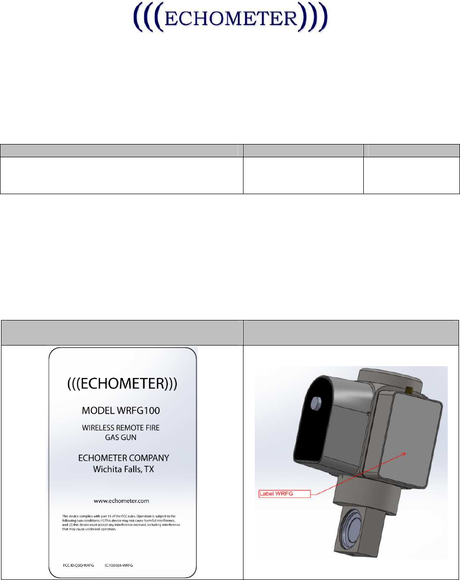
instructions. Table 2 includes the FCC Label design and Intended installation location.
Sensor Model
#
: Description
FCCID
IC ID
WRFG: Wireless Remote Fire Gun
WPP: Wireless Power Probe Q5Q-WRFG 10048A-WRFG
Table 1
Both of the above utilize the same electronic PCB, Antenna, Battery, and run the same
Firmware. The PCB in each case is packaged in a fully enclosed stainless steel enclosure.
Each model includes different transducers wired to the PCB (such as a strain gauge, or
thermistor, or microphone, or current sensor).
The instructions and pictures below depict the WRFG model. All other models will be similar
except for differences in the physical form factor.
FCC/IC Label Design
FCC/IC Label Location
Table 2
The Wireless Remote Fire Gun, (WRFG) is a component of the Echometer Well Analyzer
and designed to be used with the Echometer WB100 Wireless Base, providing a wireless
Wireless Remote Fire Gun User Guide
Echometer Company
5001 Ditto Lane
Wichita Falls, TX 76302 07 Sep 2012
option for calculating liquid level depth and bottom hole pressure. The data is analyzed by the
Echometer TAM software and utilized to provide analysis of well performance. Please refer to
the Echometer TAM User Manual for instruction specific to software operation and to
Echometer WB100 Wireless Base User Manual for instructions specific to that device.
• WARNING: Changes or modifications not expressly approved by the party responsible
for compliance could void the user’s authority to operate the equipment. This device
complies with part 15 of the FCC Rules. Operation is subject to the following two
conditions: (1) This device may not cause harmful interference, and (2) this device must
accept any interference received, including interference that may cause undesired
operation.
• NOTE: This equipment has been tested and found to comply with the limits for a Class A
digital device, pursuant to part 15 of the FCC Rules. These limits are designed to
provide reasonable protection against harmful interference when the equipment is
operated in a commercial environment. This equipment generates, uses, and can radiate
radio frequency energy and, if not installed and used in accordance with the instruction
manual, may cause harmful interference to radio communications. Operation of this
equipment in a residential area is likely to cause harmful interference in which case the
user will be required to correct the interference at the user’s expense.
• This equipment complies with the FCC RF radiation exposure limits set forth for an
uncontrolled environment. This equipment should be installed and operated with a
minimum distance of 20 centimeters between the antenna and your body.
• This Class A digital apparatus complies with Canadian ICES-003.
(Cet appareil numérique de la classe A est conforme à la norme NMB-003 du Canada)
• This device has been designed to operate with the antennas listed below. The specific
models listed or substitutes as specified below may be used.
o Pulse W1030
o Linx Tech ANT-2.4-CW-RAH-RPS: 2.4GHz
o Substitutes may be used, as long as they meet the 50Ω, <2dBi gain, RPSMA
Male requirements.

Wireless Remote Fire Gun User Guide
Echometer Company
5001 Ditto Lane
Wichita Falls, TX 76302 07 Sep 2012
WRFG Installation:
1. Install the Wireless Remote Fire Gun, (WRFG) to the well using instructions found in
the Wireless Well Analyzer manual.
2. Install the antenna as shown.
3. Press the POWER button on the WRFG as indicated below:
a. The POWER LED will indicate current status as indicated below:
• LED Off – Sensor is off.
• When the Power button is pressed, the LED will proceed with the LED
test, flashing 3 times GREEN, then 3 times RED
• Battery status is indicated by 1 to 10 quick GREEN flashes, (1 is low
battery charge, 10 is full battery charge), immediately following the LED
test
• The LED will flash GREEN once per second to indicate the Sensor is
READY
• The LED will flash GREEN twice every five seconds to indicate the
sensor is operating
• Any ERROR will be reflected by 3 quick RED flashes on the LED
4. Press the ACQUIRE button as shown below to initiate data acquisition. Use the TAM
software and its instructions to complete the test. Pressing ACQUIRE again will stop
acquisition.
a. The Acquire LED will reflect these conditions with the indicated feedback from
the LED:
• LED Off- Not Acquired
Wireless Remote Fire Gun User Guide
Echometer Company
5001 Ditto Lane
Wichita Falls, TX 76302 07 Sep 2012
• When the button is pressed, the LED will flash 3 quick GREEN flashes.
• While starting, the LED will flash GREEN approximately once per second.
• While running, the LED will flash GREEN quickly, (approximately 10 times
per second)
• Any error will be indicated by the LED flashing RED three times quickly.
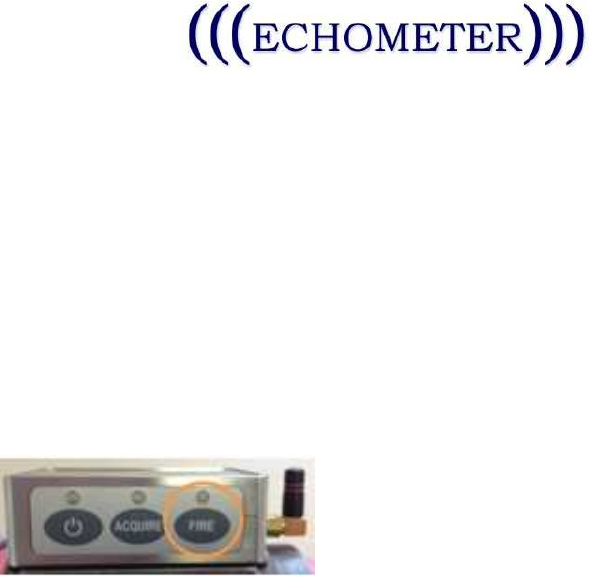
5. Press the Fire button to charge and/or fire the gun.
a. The LED will reflect status as indicated below:
• LED Off- Not Ready
• While charging to fire, the LED will flash GREEN, once per second.
• When ready to fire, the LED will flash GREEN 10 times per second.
6. To turn off the WRFG, simply press the Power button for two seconds.