Echostar Ad 3000 Ip Viaccess Users Manual ManualsLib Makes It Easy To Find Manuals Online!
2014-12-12
: Echostar Echostar-Ad-3000-Ip-Viaccess-Users-Manual-119768 echostar-ad-3000-ip-viaccess-users-manual-119768 echostar pdf
Open the PDF directly: View PDF ![]() .
.
Page Count: 31
User Manual
ANALOG/DIGITAL, POSTIONER RECEIVER WITH
EMBEDDED VIACCESS AND COMMON INTERFACE

CONTENTS
3.
4. Remote Control Unit (RCU) ------------------------------------------------------- 7
5. Getting started ------------------------------------------------------------------------ 8
7. Operation and menu program --------------------------------------------------- 13
8. Specifications ------------------------------------------------------------------------- 28
Front & rear view ------------------------------------------------------------------- 5
2. Features ------------------------------------------------------------------------------- 3
1
Trade Mark of the DVB Digital Video Broadcasting Project (1970)
A. Receiver and TV set-up ------------ ------------------------------------------- 13
B. Main menu & Installation ---------------------------------------------------- 19
C. Advanced Installation --------------------------------------------------------- 26
Appendix. Tri control database remote ----------------------------------------- 31
Safety instructions ------------------------------------------------------------------- 2
How to connect your dish to the EchoStar AD-3000IP VIACCESS ----- 11
1.
6.

WARNING!
Always follow these instructions to avoid the risk of injury to yourself or damage to your equipment.
Unplug the receiver from the AC power outlet before cleaning. Use only a damp cloth for cleaning
the exterior of the receiver.
Do not use accessories or attachments not recommended by the receiver manufacturer, as they may
cause hazards and will void the warranty.
Do not operate the receiver in high-humidity areas, or expose it to water or moisture.
Do not place the receiver on an unstable cart, stand, tripod, bracket, or table. The receiver may fall,
causing serious personal injury and damage to the receiver.
Do not block or cover slots and openings in the receiver. These are provided for ventilation and
protection from overheating. Never place the receiver near or over a radiator or heat register. Do
not place the receiver in an enclosure such as a cabinet without proper ventilation.
Do not stack the receiver on top of or below other electronic devices.
Operate the receiver using only the type of power source indicated on the marking label. Unplug the
receiver power cord by gripping the power plug, not the cord.
Route power supply cords so that they are not likely to be walked on or pinched by items placed upon
or against them. Pay particular attention to cords at plugs, convenience receptacles, and the point
where they exit from the unit.
Use an outlet that contains surge suppression or ground fault protection. For added protection during
a lightning storm, or when the receiver is left unattended and unused for long periods of time, unplug
it from the wall outlet and disconnect the lines between the receiver and the antenna. This will
provide some protection against damage caused by lightning or power line surges.
Do not attempt to service the receiver yourself, as opening or removing covers may expose you to
dangerous voltage, and will void the warranty. Refer all servicing to authorized service personnel.
Unplug the receiver from the wall outlet and refer servicing to authorized service personnel whenever
the following occurs:
The power supply cord or plug is damaged;
Liquid has been spilled, or objects have fallen into the receiver;
The receiver has been exposed to rain or water;
The receiver has been dropped or the chassis has been damaged;
The receiver exhibits a distinct change in performance.
2
1. Safety Instructions

2. Features
1. Satellites : up to 50 satellites, 999 transponders
2. 4-digit 7-segment LED on the front panel displays channel information
3. Displays local time on the front panel in stand-by mode
4. Proprietary EchoStar OSG menu
5. 64-step volume control
6. VCR timer function (position, Digital/Analog, channel, start time, stop time)
7. Power recovery function
8. Last channel memory function
9. Favorite channel function (mixed Digital & Analog)
10. C/Ku control function
11. Parental lock / Installation & Edit lock / Receiver lock
12. Variety of LNB polarity control; 13/18V, 0/22kHz tone, 0/12V,
Mechanical polarizer, magnetic polarizer (Ferrite) and DiSEqC 1.0TM
13. RS232C port for additional information service and update of the receiver control software
14. DiSEqC 1.0TM compatible
15. Mechanical and magnetic polarizer control for each satellite
16. Auto Sat position search
17. Channel storing for multi satellites
18. Built-in positioner (high power azimuth control (36Vdc, 5A ))
3
Common Section

1. MPEG-2 Video (MP@ML)
2. MPEG-1 Audio layer 1, layer 2
3. MPEG-2 Digital & fully DVB compliant
4. Viaccess embedded with 1 smart card
5. Capable of interfacing with the CAMs of DVB Common Interface standard
6. Capable of scanning the frequency for SMATV system
7. On-screen display with 256-color full resolution
8. Plug & Play installing program set-up
9. LD quality video, CD quality audio
10. RS232C port for additional information service and update of the receiver control software
11. Displays signal level to set up the satellite antenna with ease
12. Powerful editing facilities;
; PIDs, TV or Radio channel, channel name, satellite name, transponder name
13. Teletext function (Your TV should support teletext.) & Subtitling
14. SCPC/MCPC receivable from C/Ku-band satellites
15. Variable aspect ratio (4:3, 16:9) with pan vector
16. EPG for on-screen channel information
17. Multi-lingual function when provided by the satellite and broadcasting service provider
18. Total 5000 channels programmable (4000 Channels for TV & 1000 Channels for Radio)
19. S/PDIF(Sony/Philips Digital Interface) for the digital audio
Digital Section
1. 700 programmable channels
2. 1 IF input (900-2150MHz) / 1 bandwidth (27MHz)
3. 32-step low threshold extension (3dB)
4. Audio mono / stereo selectable
5. C/ Ku band (invert/ normal video format) selectable
6. 4 video level control
7. 4 decoder modes
8. Color GUI (Graphic User Interface) menu
(overlaid with digital graphic OSG menu and analog background live picture)
9. Powerful editing facilities; channel name, satellite name
Analog Section
4
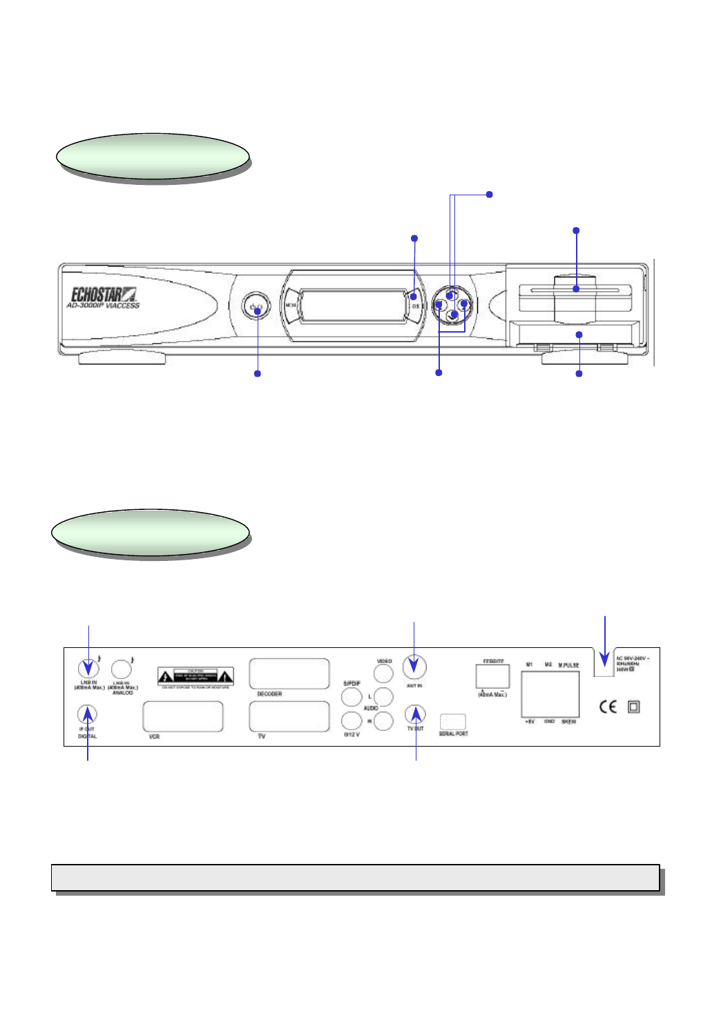
Front Panel
Front Panel
3. Front & Rear View
Rear Panel
Rear Panel
5
AC power cord
RF output connector to TV
Antenna input
LNB input
Loop through
Note: All the cables used for Input/Output connection for the receiver should be well shielded.
Note: All the cables used for Input/Output connection for the receiver should be well shielded.
Selection / conf
irmation
Channel up / down
Volume up / down 2 Slots for CI module
ON/Standby
1 Smart card slot

Smart Card and CI Module
To watch payable program channels, a CI module and a smart card from the service provider is necessary.
(The service provider is the distributor of the programs). CI modules and smart cards are only licensed to
service providers only and they are distributed by their dealers or agents.
If you are subscribed to the services of more than one service provider, you might have to insert or change
proper smart card and proper CI module of your choice.
Without CI module and smart card,only FTA (free-to-air) programs are available to watch.
Note : 1) The main plug must not be plugged in before inserting the CI module.
2) Insert the CI module fully into the slot behind the lid in the front panel of the receiver,
towards the arrow on the module facing upwards and inwards.
3) Insert your smart card fully into the slot on the CI module towards the arrow on the card facing
upwards and inwards.
4) CI module and smart card may give special menus which are not described in this manual.
5) A smart card is connected to a single service provider and to a specific range of channels.
6
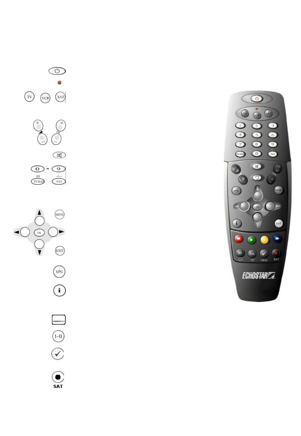
4. Remote Control Unit (RCU)
7
The Power key turns the receiver on and off.
The LED (Light Emitting Diode) flashes red to show the remote is working.
The TV, VCR and SAT keys select the device to be controlled.
Pressing the SAT key allows the remote to control the functions
of the receiver.
The Volume and Channel keys control the two most
frequently used functions of the receiver.
The Mute key switches the sound on and off.
The MENU key is used to see main menu or to return to previous
menu.
The cursor keys are for channel ?and ? and volume ? and ?.
The OK key is used to select a program, a highlighted line or
parameter value. Also you can see TV/Radio channel list while
watching TV or listening to the radio.
The EXIT key exits to the video viewing mode at any time.
Number / Input keys enable direct channel selection command
selection using numeric keys.
The TV/RAD(Radio) key switches between TV and radio mode.
The FAV key shows a list of your selected favorite channels (To
define channels as favorite select the “Edit TV channel” menu).
The EPG key shows program information of the selected channel.
(EPG; Electronic Program Guide)
The Subtitle key enables subtitling (only when provided by the broadcaster).
Selects the Audio Language or Soundtrack from among the data transmitted for the current
channel.
Shows a thumb nail representation of the current channel in the “Edit TV Channel”,
“Parental Lock” and “EPG”.
The SAT key shows a list of selectable satellites.
VIEW
The Information key provides additional information about the
current channel and program (only available when provided by
the broadcaster). In the menus pressing this key provides up to
four lines of help.
DO NOT PLUG the receiver into Main Power Outlet, until you complete all the connections to the receiver.
DO NOT PLUG the receiver into Main Power Outlet, until you complete all the connections to the receiver.
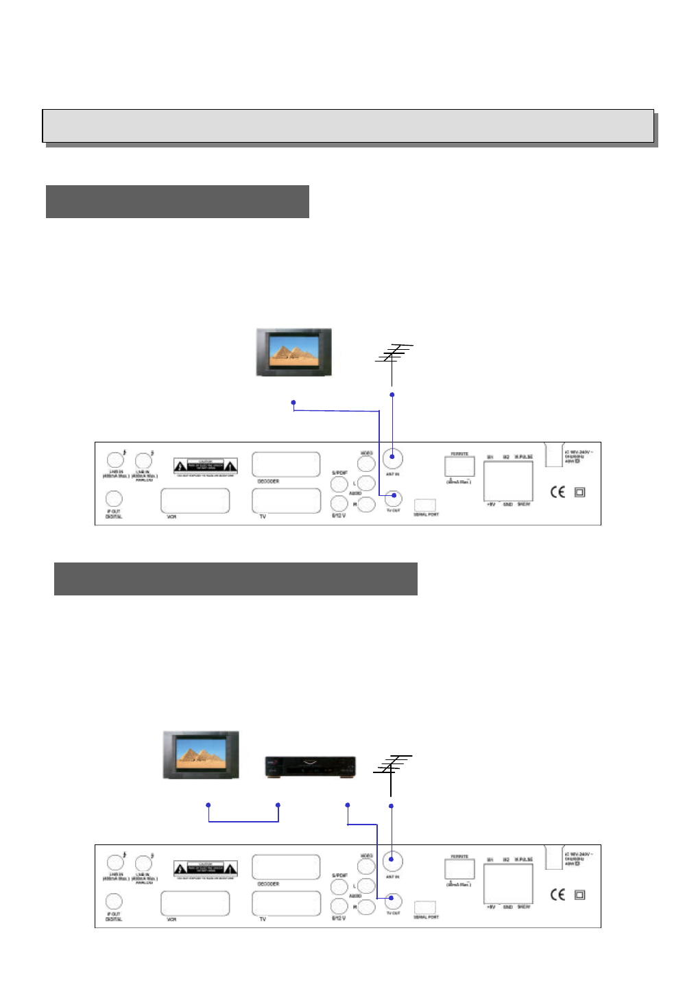
5. Getting Started
TV ANTENNATV
RF IN
8
Receiver to TV with RF
VCR
TV
RF IN RF INRF OUT
Receiver to VCR and then to TV with RF
1. Connect the Off-air TV antenna or cable if available to the ANT IN socket of the EchoStar AD-3000IP VIACCESS.
2. Connect the TV OUT socket of the EchoStar AD-3000IP VIACCESS to the RF IN of the TV set.
3. Search on the TV set for UHF channel # 38. This is the default channel where the EchoStar AD-3000IP VIACCESS
is set to.
1. Connect the Off-air TV antenna or cable if available to the ANT IN socket of the EchoStar AD-3000IP VIACCESS.
2. Connect the TV OUT socket of the EchoStar AD-3000IP VIACCESS with the RF IN of the VCR.
3. Connect the RF OUT of the VCR to the RF IN of the TV set.
4. Search on the TV set and the VCR for UHF channel # 38. This is the default channel where the EchoStar AD-3000IP VIACCESS
is programmed to.
Note : Use different UHF channels for VCR and EchoStar AD-3000IP VIACCESS.
TV ANTENNA
TV ANTENNA
TV
RF IN
9
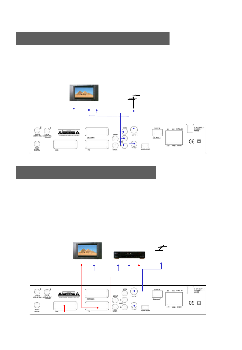
Receiver to TV with Audio and Video RCAs
VIDEO AUDIO
IN IN
Receiver to TV and VCR with SCART Cables
1. Connect the Off-air TV antenna or cable if available to the ANT IN socket of the EchoStar AD-3000IP VIACCESS.
2. Connect the TV OUT socket of the EchoStar AD-3000IP VIACCESS with the RF IN of the VCR.
3. Connect the RF OUT of the VCR to the RF IN of the TV set.
4. Search on the VCR for UHF channel # 38. This is the default channel where the EchoStar AD-3000IP VIACCESS is programmed to.
5. Connect the SCART cable from the TV SCART of the EchoStar AD-3000IP VIACCESS to the SCART of the TV set.
6. Connect the SCART cable from the VCR SCART of the EchoStar AD-3000IP VIACCESS to the SCART of the VCR.
7. When the EchoStar AD-3000IP VIACCESS is switched on the TV set, TV set will automatically switch to the relevant SCART
input of the TV.
Note : Use different UHF channels for VCR and EchoStar AD-3000IP VIACCESS.
TV SCART RF IN RF OUT RF IN VCR SCART
1. Connect the Off-air TV antenna or cable if available to the ANT IN socket of the EchoStar AD-3000IP VIACCESS.
2. Connect the TV OUT socket of the EchoStar AD-3000IP VIACCESS with the RF IN of the TV set.
3. Connect the Video and Audio RCAs of the EchoStar AD-3000IP VIACCESS to the Video and Audio RCAs of the TV set.
TV ANTENNA
VCR
TV
10
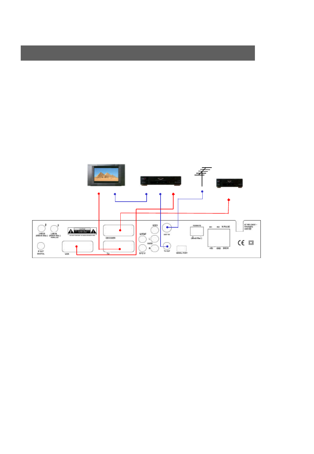
Receiver to TV, VCR and Decoder with SCART Cables
DECODER
DECODER SCART
1. Connect the Off-air TV antenna or cable if available to the ANT IN socket of the EchoStar AD-3000IP VIACCESS.
2. Connect the TV OUT socket of the EchoStar AD-3000IP VIACCESS to the RF IN of the VCR.
3. Connect the RF OUT of the VCR to the RF IN of the TV set.
4. Search on the VCR for UHF channel # 38. This is the default channel where the EchoStar AD-3000IP VIACCESS is
programmed to.
5. Connect the SCART cable from the TV SCART of the EchoStar AD-3000IP VIACCESS to the TV SCART from the TV
set.
6. Connect the SCART cable from the VCR SCART of the EchoStar AD-3000IP VIACCESS to the SCART of the VCR.
7. Connect the SCART cable from the DECODER SCART of the EchoStar AD-3000IP VIACCESS to the SCART of the
DECODER.
Note : Use different UHF channels for VCR and EchoStar AD-3000IP VIACCESS.
TV SCART RF IN RF OUT RF IN VCR SCART
TV ANTENNA
VCR
TV
11
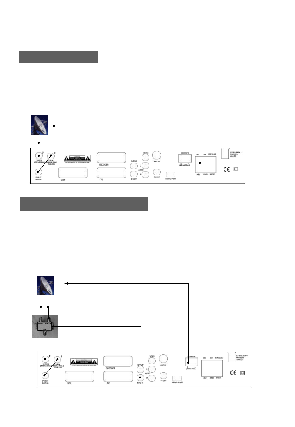
One Actuated Dish
1. Connect the IF OUT and LNB IN connectors using the loop through cable provided with the EchoStar AD-3000IP VIACCESS.
2. Connect the LNB IN socket of the EchoStar AD-3000IP VIACCESS to the LNB.
3. Connect motor wires to M1 and M2. Switch these connections if the motor moves to the wrong direction.
4. Connect sensor wires to M.PULSE and GND connector.
5. Connect a mechanical polarotor to +5V, GND and SKEW connectors. [optional]
6. Connect ferrite polarizer to ferrite connectors. [optional]
Universal LNB
6. How to connect your dish to the EchoStar AD-3000IP VIACCESS
One Actuated Dish with C/Ku feed
C-band Ku-band
LNB LNB
ACTUATED DISH
WITH C/KU FEED
1. Connect the IF OUT and LNB IN connectors using the loop through cable provided with the EchoStar AD-3000IP VIACCESS.
2. Connect the cables from C and Ku-band LNB to a 12 Volt C/Ku switch.
3. Connect the coaxial cable from the 0/12 Volt switch to the LNB IN connector.
4. Connect the power cable which comes from the 0/12 Volt switch to the 0/12V(connector).
5. Connect motor wires to M1 and M2. Switch these connections if the motor moves to the wrong direction.
6. Connect sensor wires to M.PULSE and GND connector.
7. Connect polarotor to +5V, GND and SKEW connectors. [optional]
12
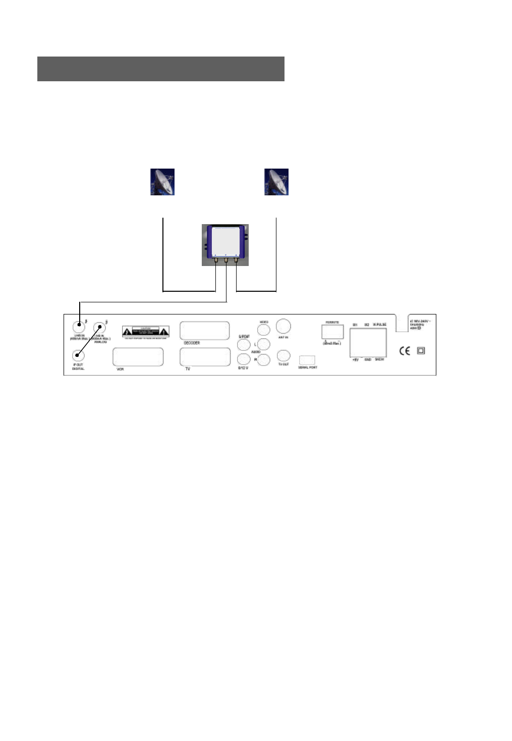
Two Fixed Dishes using DiSEqC mode
1. Connect the IF OUT and LNB IN connectors using the loop through cable provided with the EchoStar AD-3000IP VIACCESS.
2. Connect the DiSEqC 1.0 or Toneburst switch to the LNB IN connector of the EchoStar AD-3000IP VIACCESS.
3. Connect both dishes to the 2 inputs from the DiSEqC switch.
LNBLNB
FIXED DISH # 1
(Digital or Analog) FIXED DISH # 2
(Digital or Analog)
DiSEqC switch
A. Receiver and TV set-up
Check the Installation
To get the most out of the EchoStar AD-3000IP VIACCESS it should be correctly installed, the dish
should be optimally aligned and the mechanical limit switched on the dish should be set properly.
Press /I on the remote control unit (RCU) or press on the front panel of the EchoStar AD-3000IP
VIACCESS to switch the unit on.
5. Operation and Menu Program
13
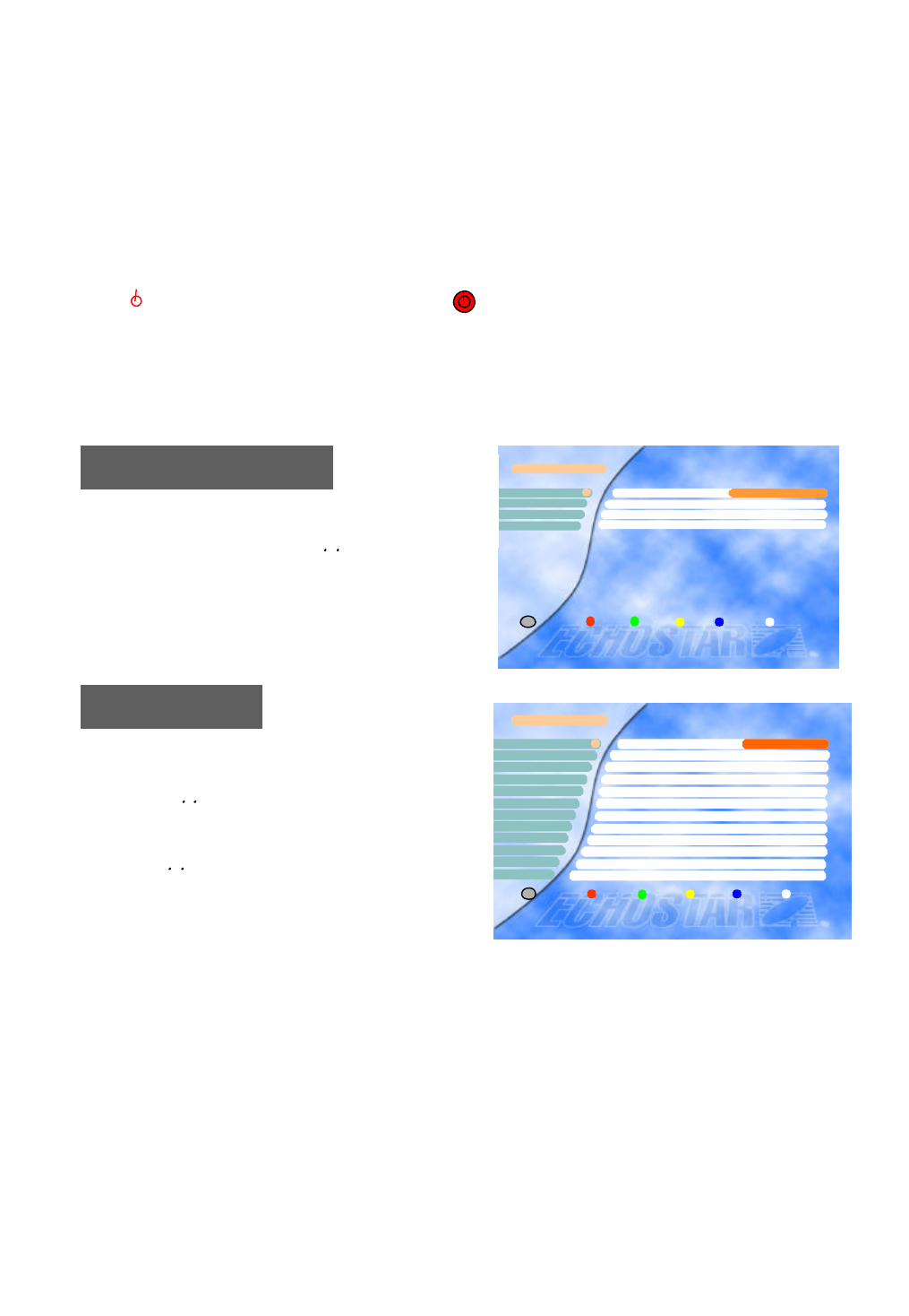
The receiver is supplied with factory setting and will start up with the “Language Setting” menu.
After selecting the language settings, the ”LNB Setting” menu will be shown. Please follow the steps outlined
below to properly install the EchoStar AD-3000IP VIACCESS.
You can select the desired language for the OSG (On-
Screen Graphics) display using the , keys when the
“Menu Language” option is selected. Similarly you can
selected a different audio channel when the “Audio
Language” option is selected. This option allows you to
select a different language to listen to if supported.
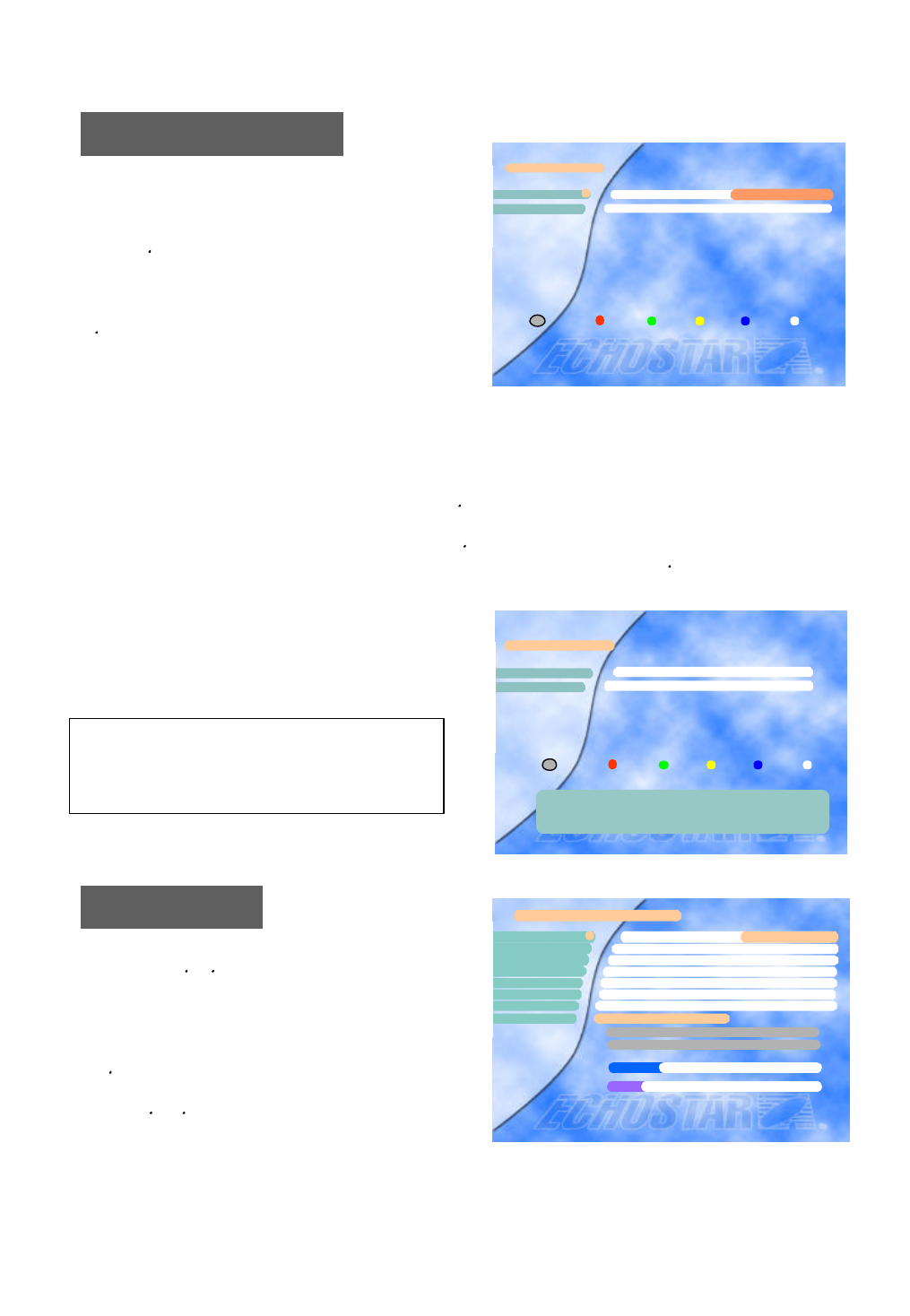
LNB Setting
Select the LNB type which conforms to your LN
B using the , keys.
Other parameter values should be changed
manually according to your LNB type.
Press the OK key to confirm your selection.
Select the “LNB Setting” menu in the “Installation” m
enu using the , keys.
If you have a Mechanical Polarizer with your LNB, you have to set the “Polarity Control” parameter in this
menu to [Polarotor].
If the Loopthrough option is set to ON, the Loopthrough ports should be set according to the diagrams on
pages 11. If no Loopthrough is used this option should be set to OFF.
LNB Setting
LNB Freq.Low 5150
LNB Freq. High 5150
DiSEqC DiSEqC 1..4
DiSEqC Port 1
Polarity Control 13/18V
LNB Freq. Band Control 0/12V
Ku/C Control Disable
LNB Type Index (1..8)
0/22kHz Control Off
0/12V Control Off
LNB Power On
Loopthrough for Analog On
1
2
4
3
5
6
7
8
9
10
11
× Type 1 Ø
i
Exit
12
Language Setting Language Setting
Menu Language
Main Audio Language English
× English Ø1
22nd Audio Language English
Subtitle Language English
3
4
Exit
i
14
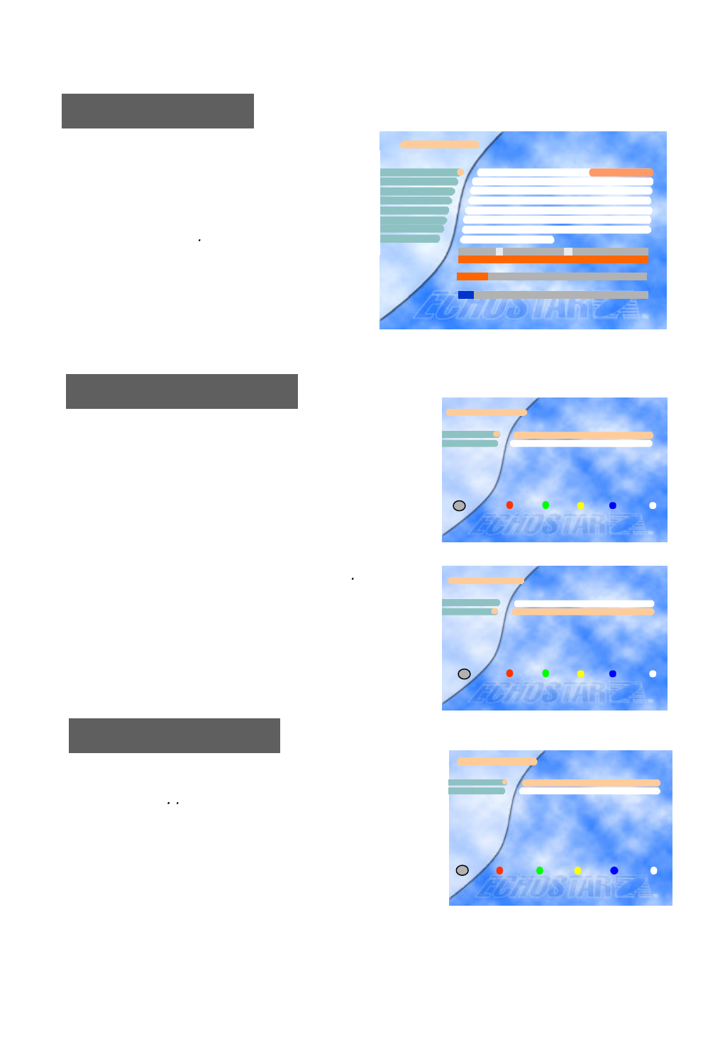
Move the dish a few counts to the west by pressing the key and press the OK key to store east limit in this p
osition. The indicated number will be set at 1000 and the highlight will be moved down to the “West Limit” li
ne. Now set the west limit by moving the dish using the key until you have reached the dish limit. The indica
ted number will increase from 1000. Move the dish back a couple of counts using the key and press the OK
key to store the west limit.
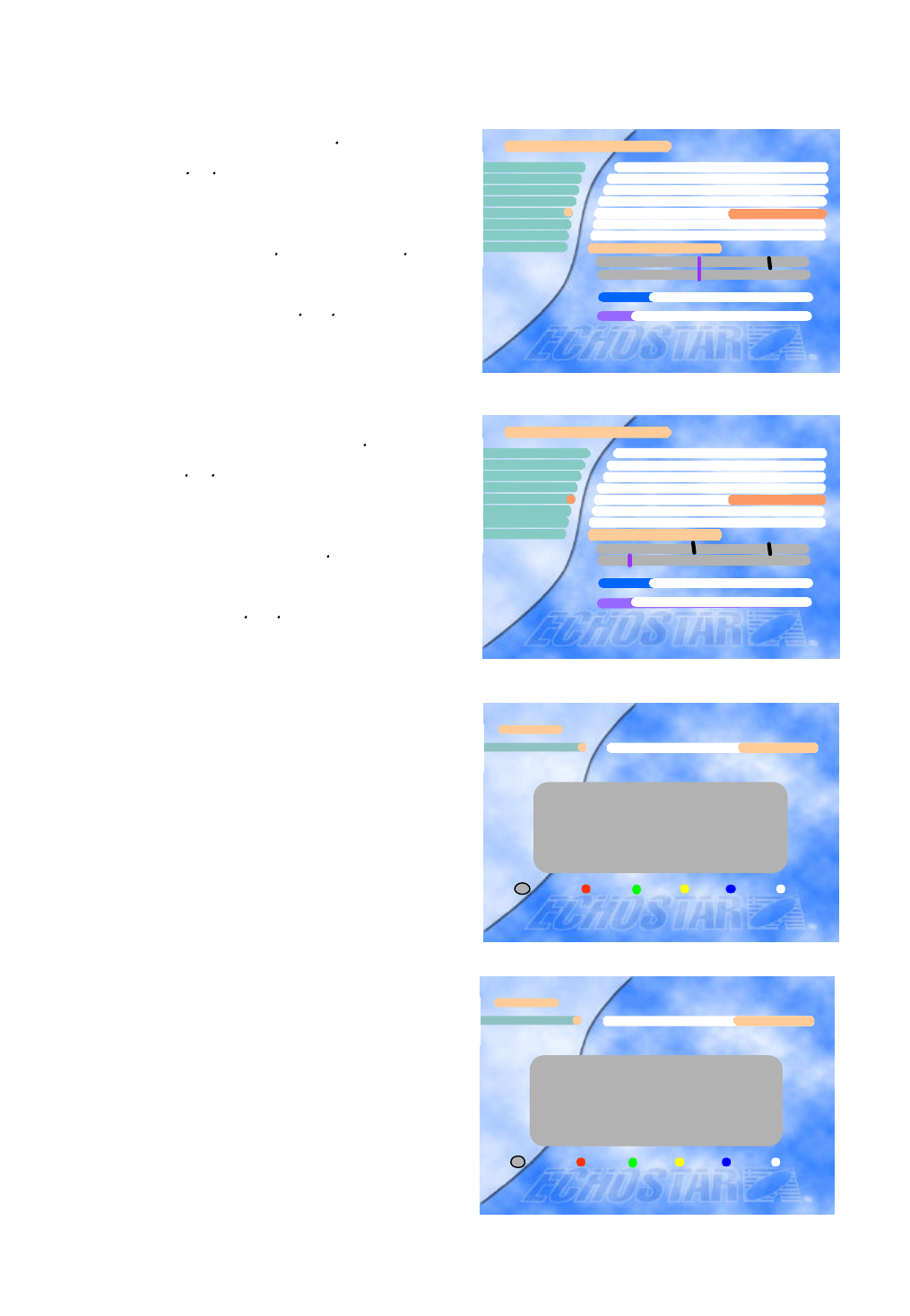
If either the numeric value is not shown or the message
“...Motor Error...” is displayed on the lower left part of t
he screen, then,
Press the key on the “East Limit” parameter line.
The initial value of 5000 will decrease as the dish i
s moved. Keep moving the dish unit the east limit i
s reached. If the dish to the west when you press th
e key, reverse the motor wires.
Antenna Installation
First the east and west limits have to be set before
any satellites can be programmed.
The dish limits are now stored in the receiver and t
he dish is the most western position. Press the SA
T key to start the “Auto Sat” function or you can pr
ess MENU to program the satellites manually.
If you do not have a moveable dish, just press the
OK key twice to program the east and west limit in
the same position. This will be indicated by a
numeric value of 1000 for both limits.
1) an error occurred when moving the dish(which could be caused by i.e. loose wires), or
2) the dish has reached its east limit. In this case continue with the installation procedure.
Antenna Installation
East Limit
West Limit Not Set
i
Exit
× Not Se t Ø1
2
Antenna Installation
West Limit 1070
East Limit 1000
1
2
i
Exit
Press SAT to go to the Auto SAT feature.
Press menu if you want to program the satellites manually.
Press Exit to return to TV/Radio channel.
Now press the or key to select the most western
position you can receive.
Press the OK key.
Select the Position option and move the dish using
the key to correct location of the western satellite.
Peak the dish to obtain the highest signal quality
using the and keys. Then press the OK key to
store this setting.
8
Please Store most western satellite
Satellite 018.0° W
LNB Type Type1
TP/Polar/SR(Digital) 11525/H/12225
Skew Not set
Position E 1000 W
Realign dish +00
Search type Auto Search
Start Search(Press OK)
2
3
4
5
× INTEL705 Ø1
EL WL
Signal Level
Signal Quality
6
7
11%
00%
8
Auto SAT
Go back to the Satellite option using the key.
Now press the or key to select the most
eastern satellite you can receive.
Press the OK key.
Select the Position option using the key move
the dish to the correct location of the eastern
satellite. Peak the dish to obtain the highest
signal quality using the and keys.
15
Press the SAT key to let the receiver calculate all
intermediate satellite positions. All selected satellite
positions are now stored for both the digital and
analog mode.
Press the MENU key twice to return to the installation
screen. Select Auto Channel Search (for more
information on this option please refer to page 20).
The EchoStar AD-3000IP VIACCESS will start the
search on the most eastern satellite.
ü CAKRAWAR 107.7° E ü THAICOM 078.5° E
ü ASIASAT3S 105.5° E ü APSTAR2R 076.5° E
ü GORIZT25 103.0° E ü PAS4 068.5° E
ü ASIASAT2 100.5° E ü ASTRA1 018.0° E
ü ABC 100.5° E
ü MESAT 091.5° E
ü ST1 088.0° E
ü INSAT2E 083.0° E
* Page Change = Ú,Ù
* Press SAT to Calculate satellite positions
Auto SAT
Select Satellite 019.2 °E× ASTRA1 Ø
i
Delete Add Exit
1
Please Store most eastern satellite
Satellite 004.0 ° W AMOS1
LNB Type Type1
TP/Polar/SR(Digital) 11224/H/27500
Skew Not set
Position
Realign dish +00
Search type Auto Search
Start Search(Press OK)
1
2
3
4 E 1053 W
EL WL
Signal Level
Signal Quality
6
7
8
12%
00%
5
ü CAKRAWAR 107.7° E THAICOM 078.5° E
ASIASAT3S 105.5° E APSTAR2R 076.5° E
GORIZT25 103.0° E PAS4 068.5° E
ASIASAT2 100.5° E ü ASTRA1 018.0° E
ABC 100.5° E
ü MESAT 091.5° E
ST1 088.0° E
INSAT2E 083.0° E
* Page Change = Ú,Ù
* Press SAT to Calculate satellite positions
Auto SAT
Select Satellite 019.2 °E× ASTRA1 Ø
i
Delete Add Exit
1
Go back to Satellite option using the key.
Now press the or key to select the middle
satellite.
Press the OK key.
Select the position using the key and with the
key move the dish to the correct location of the
middle satellite. Peak the dish to obtain the
highest signal quality using the and keys.
Then press the OK key to store this setting
Please Store middle satellite
Satellite 028.2° E ASTRA2
LNB Type Type1
TP/Polar/SR(Digital) 11478/H/30000
Skew Not set
Position
Realign dish +00
Search type Auto Search
Start Search(Press OK)
2
3
4
E 1238 W
EL WL
Signal Level
Signal Quality
6
12%
00%
1
5
[ E 1238 W ]
7
8
16
Go in to the “Motorized dish setting” menu with the key to “E
rase Position Data” and press the OK key. Then go to “Erase
All Satellite Data” press the red key twice. Press the MENU k
ey, go to Installation, Motorized Dish Setting, Antenna Installat
ion, press the OK key and proceed from start.
If you are not satisfied with the Limit parameters e.g. since the
mechanical limits might not be set properly, you can erase the
position data and start again after adjusting the mechanical
limits at the dish.
Motorized Dish Setting
Erase Position Data
Select in the Erase Position Data Menu “Set Present Sat as f
ixed”, using the , keys.
If signals from this satellite are received with a fixed dish, th
e movable dish will not move to this satellite.
Erase Position Data
Erase All Satellite Data
Set present SAT as fixed1
2
Delete Cancel
i
Exit
Motorized Dish Setting
Erase Position Data
Antenna Installation
2
1
Exit
i
Motorized Dish Setting
Erase Position Data
Antenna Installation
1
2
Exit
i
The EchoStar AD-3000IP VIACCESS now has
programmed the position of all selected satellites.
The next step is to store all channels on these
satellites. To do this press the MENU key, select
the Installation option followed by the Program
Satellites option. Use the key to select the next
satellite and press the OK key. The dish will
move to the selected satellite.
Select Start Search to store all channels.
Repeat this procedure for all satellites.
Program Satellites
LNB Type Type 1
TP/Pol/SR(Digital) 11662/V/27500
Skew Not set
Position E 1070 W
Re-align Dish +00
Search Type Auto Search
Start Search (Press OK)
Satellite 013.0?E1
2
43
5
6
7
8
× HOTBIRD Ø
[E 1070 W]
EL WL
Signal Level 10%
Signal Quality 5%
Program Satellites
User’s Setting
17
Local Time Setting
User’s Settings are only accessible via the Installation screen.
Language Setting
Subtitle
None
Eng
Ita
Subtitle
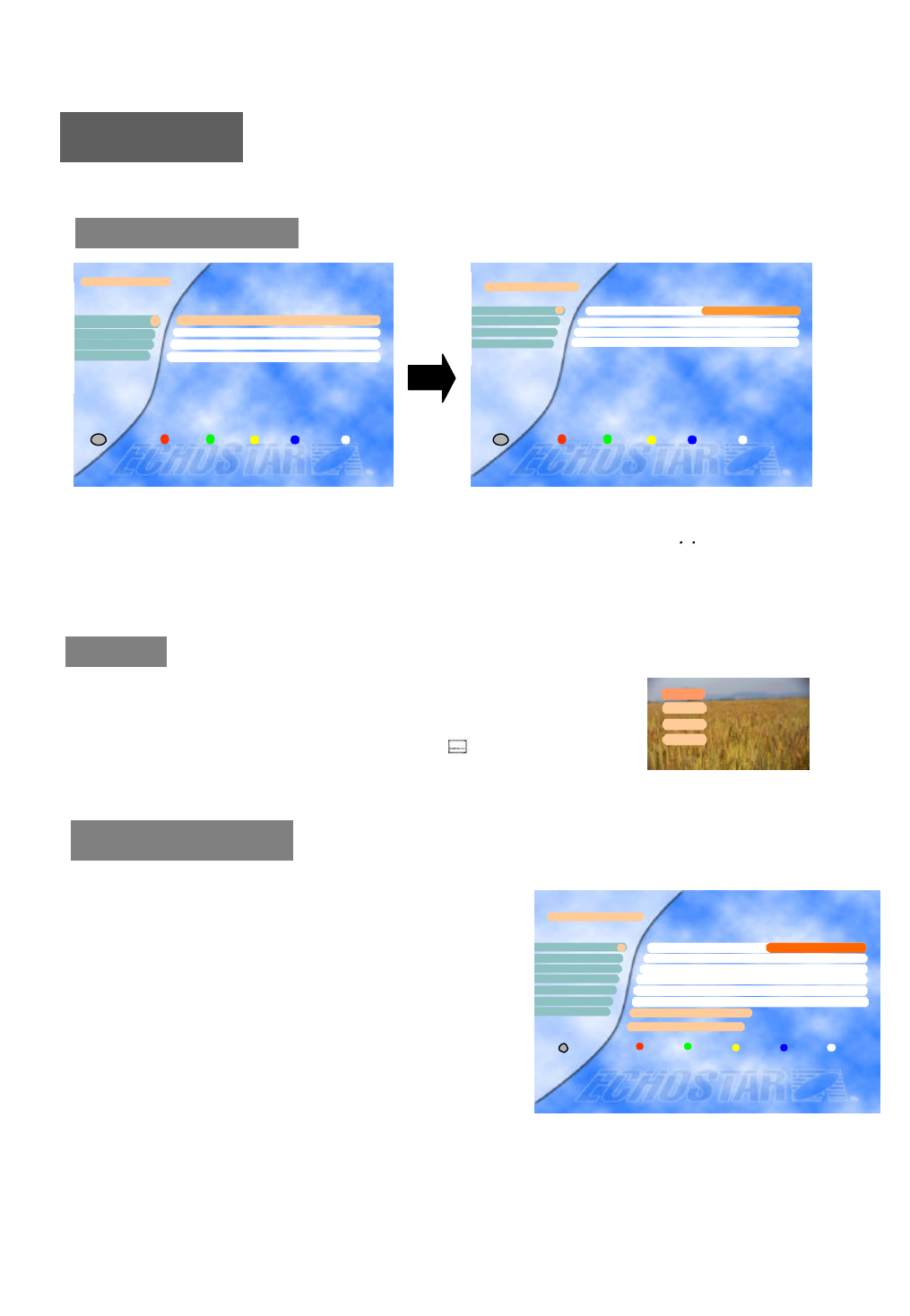
Select the “Subtitle Language” in the “Language Setting” menu. While viewing a
channel, the subtitling option is available only when the selected subtitling language
is provided by the broadcaster.
To check if the subtitling language is available, press “ ” key on the remote
control unit, to show a list with all available subtitling languages.
To set your local time, input all the required data for the time
and date. This information has to be entered to enable
recording of the programs of your choice.
After entering the correct data for year, month, date, day,
hour, minute, select option 7 (Press the OK key to set the
time) and press the OK key to save the data.
It is recommended that the time and date set in this menu is
the same as of your VCR.
Now that the date and time has been set you could edit the
VCR timer settings.
You can select the desired language for the OSG (On-Screen Graphics) display using the , keys when the
“Menu Language” option is selected. Similarly you can select a different audio channel when the “Audio
Language” option is selected. This option allows you to select a different language to listen to if supported.
User’s Setting
Local Time Setting
A/V Output Setting
About Echostar
Language Setting
3
1
4
2
Exit
i
Language Setting
Menu Language
Main Audio Language English
× English Ø1
22nd Audio Language English
Subtitle Language English
3
4
Exit
i
Local Time Setting
Year
Month Jan.
Date 01
Day Sun.
Minute 00
Hour 00
Local Time = --:--
1
3
6
2
4
5
Press OK to set the time
iExit
× 1999 Ø
7

Please select your TV format.
4:3 for normal screen TV
16:9 for wide screen TV
Aspect
A/V Output Setting
18
About EchoStar
You can see the details of the company
information.
If you have any questions about the EchoStar
AD-3000IP VIACCESS, firstly contact your l
ocal dealer.
You can select the time out
time(2,3,4,5,8,10 secs) of the banner
information about the current channel and
program using the , keys.
Banner
You can select the type of Video standard by using the , keys.
* Video standard : PAL B/G,I , D/K
Select the vacant channel considering your local channels and preset channels below.
* Pre-set : Ch 38 for PAL B/G,I Ch 40 for PAL D/K
UHF frequency is set automatically according to the channel selection.
UHF Tuning
Sub.backg.Select ‘On’ for Subtitle background on TV (Subtitle background).
i
Company info
Exit
Company Echostar Intl. Corp.
Address Schuilenburglaan 5a
City 7604 BJ Almelo
About Echostar
Fax Number +31 546 814691
Phone Number +31 546 815122
Country Netherlands
Unit AD-3000IP VIACESS
Software version XXXXXX
Home page HTTP://www.echostar.nl
Unit info
A/V Output Setting
Aspect
Banner 3Sec
Sub. backg. On
PAL B/G
Frequency = 607.25MHz
Channel 38
<<< UHF Tuning >>>
2
3
5
4
1
iExit
× 4:3 Ø
19
Installation
B. Main menu and Installation
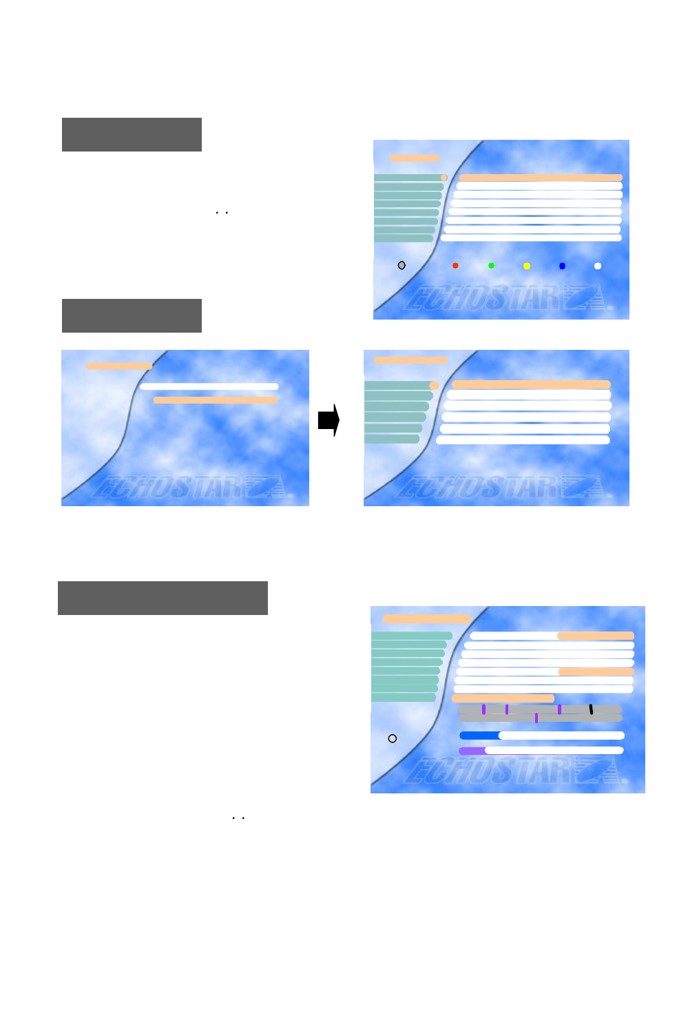
Press the MENU key to display the “Main Menu” o
n the screen.
Main Menu
Select a sub-menu using the , keys or the numeric k
eys. Please note that the OK key is always a confirma
tion of your selection. To go back to the previous me
nu, press the MENU key.
The Installation Lock,“Enter PIN code” menu is displayed only when the Installation and Edit Lock is se
t as [ON]. The initial code is set as [0000] but you can change it (See “Change PIN code” on page 21).
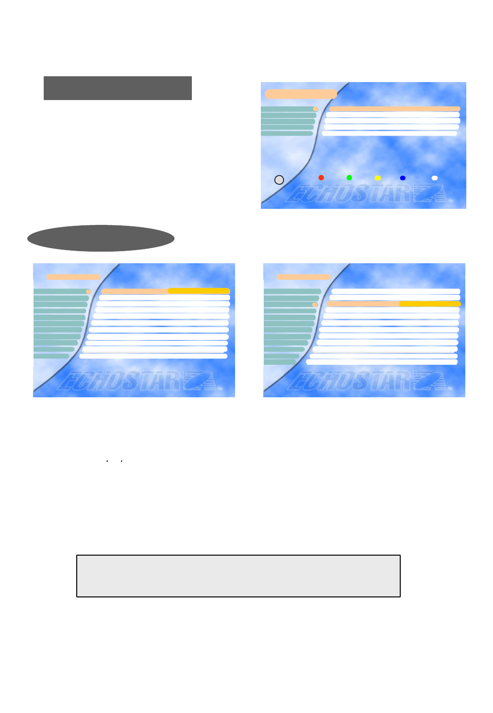
Program Satellites
In some cases it might be necessary to reposition all satellites at once. This can be achieved with the “Re-align di
sh”option.
You can move the dish using the , keys when the “Position” option is selected. . To locate a satellite move the
dish until you have the location of the satellite at which the best signal quality is achieved. Press the OK key wh
ile still on the “Position” option the store the position. The stored locations for each satellite are shown above th
e Signal Level bar.
If you are unable to get any signal quality, please check the LNB Setting to ensure you have selected the correct
LNB and switch settings.
This menu is to align your dish to the selected satellite.
If you set the “Polarity Control” parameter in the “LNB
Setting” menu as “Polarotor” or “Ferrite”, you can adjust
the “Skew” parameter in this menu while you are watchi
ng the signal level at the same time.
Refer to the Signal Quality bar and the Signal Lev
el bar at the bottom of the screen. It is recommend
ed that the signal is at the Medium level or higher.
If it is not , please adjust your satellite dish.
Main Menu
TV Channels
Radio Channels
Parental Control
VCR Timer
Edit
Installation
Select Satellite
Conditional Access
32
5
6
7
Exit
8
4
I
1
Installation
SMATV Configuration
User’s Setting
LNB Setting
Motorized Dish Setting
Program Satellites
1
4
3
5
6Advanced Installation
2
Enter PIN Code
[ ? ? ? ?]
Installation Lock
7
8
Program Satellite
Satellite 028.2° E
LNB Type Type1
TP/Polar/SR(Digital) 11478/H/30000
Skew Not set
Position
Re-align dish +00
Search type Auto Search
Start Search(Press OK)
2
3
4
E 1172 W
EL WL
Signal Level
Signal Quality
6
12%
00%
1
[ E 1172 W ]
× ASTRA2 Ø
5
i
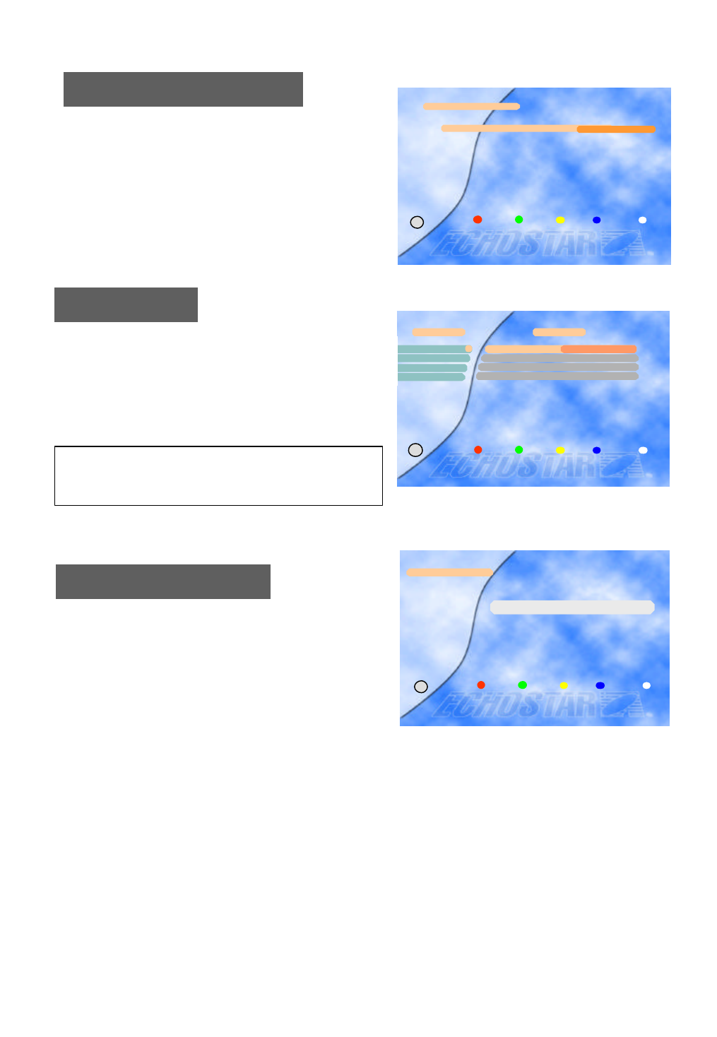
Note: To stop searching press the key on the
Using the Auto Search option, the EchoStar AD-3000IP
VIACCESS searches for all available channels(Radio and
TV) on the currently selected satellite. The names of the fo
und TV channels are shown on the left and the total numb
er of found TV and Radio channels are mentioned on the r
ight.
Auto Search
A Satellite Master Antenna Television (SMATV) system
which is intended for the distribution of television and
sound signals to household in one or
6 more adjacent buildings.
A SMATV System represents a means for sharing
the same resources among several users for satellite and
terrestrial reception, and it is designed to perform
the adaptation of the satellite TV signals to the SMATV
channel characteristics.
EchoStar AD-3000IP VIACCESS VIACCESS has a SMATV-IF facility to operate with SMATV.
This configuration allows the direct distribution of the QPSK signal received from the satellite
to the SMATV-IF distribution network in the extended IF band (above 950 MHz).
Before you start, you have to check your condition whether it is possible to use this facility or not in your
households. (You can ask your household supervisor.)
If EchoStar AD-3000IP VIACCESS VIACCESS is connected to a SMATV network, select “SMATV
Configuration”.
The most common alternatives for “Symbol rate” and “FEC” are already preprogrammed.
(When you need to change the “Symbol rate” for the exceptional frequency, select as you know.)
Move to “Start Auto Search” and just press OK.
Then, the “Auto Search” procedure will start.
To cancel the processing while the “Auto Search” is proceeding, press the MENU key.
SMATV Configuration
20
SMATV Configuration
Symbol rate alternative 2 27500
Symbol rate alternative 3 27500
FEC AUTO
Start Auto Search
Symbol rate alternative 11
2
43
5
× 27500 Ø
i
Exit
Auto Search
ASTRA1
Channel searching status
0% 50% 100%
Found TV ch. : 240
Found RAD. Ch. : 100
Index Freq SR FEC Polarity
45 12670 22000 5/6 vertical
Arte
Beta BC
BD1
Estilo
Musicals
Reqqae
remote control or on the front panel. This
cancels the searches and the found
channels will be discarded. All other keys
of the remote are disable during searching
21
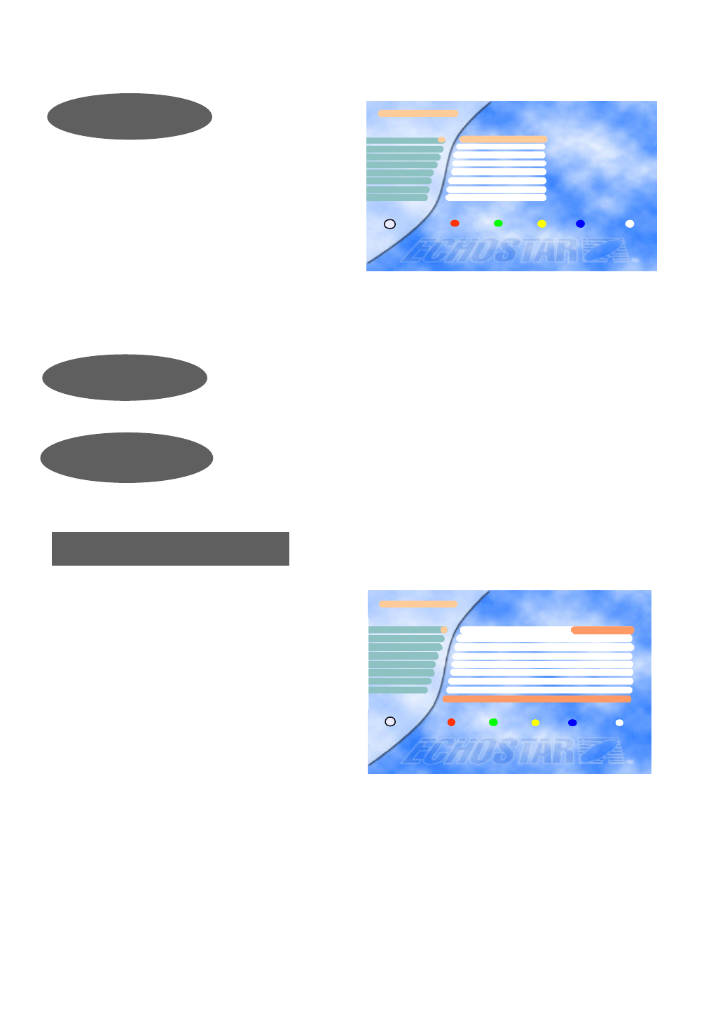
Parental Control
With parental control it can be prevented that a TV channel can be watched, a Radio Channel can
be heard, the receiver settings can be changed or an unauthorized change in the installation is
performed.
TV Channels
You can select the channel you would like to watch either b
y pressing the numeric keys for the channel number or by m
oving the highlighted bar to the channel of your choice usin
g the , keys. Press the OK key to select the channel.
* Press the , keys to move one page up or down.
Radio Channels
TV Channels
Voyage F
Contact TV F
LC I F
Cabal J F
Paris Premere F1
2
4
3
5
ASTRA1 019.2?E >
6
87JDF 1 Info-Kanal F
Star Kino F
CNN F
The pre-programmed PIN (Personal Identification Number) code is set as
[0000]. If you want to change it, please follow the procedure shown as
before.
Change PIN Code
Enter PIN Code
[ ? ? ? ?]
Parental Control
Exit
i
Parental Control
TV Channel Lock
Radio Channel Lock
Receiver Lock Off
Installation & Edit Lock Off
Change PIN Code
1
2
43
5
Exit
i
Radio Channel
Hit Liste F
Classic rock F
Soft Rock F
2
3
4
Blues F
Generation ROC F
Love Songs F
Dance F
REE F
5
76
8
ASTRA1 < 019.2? E >
1
You can select the channel you would like to watch either b
y pressing the numeric keys for the channel number or by m
oving the highlighted bar to the channel of your choice usin
g the , keys. Press the OK key to select the channel.
* Press the , keys to move one page up or down.
22
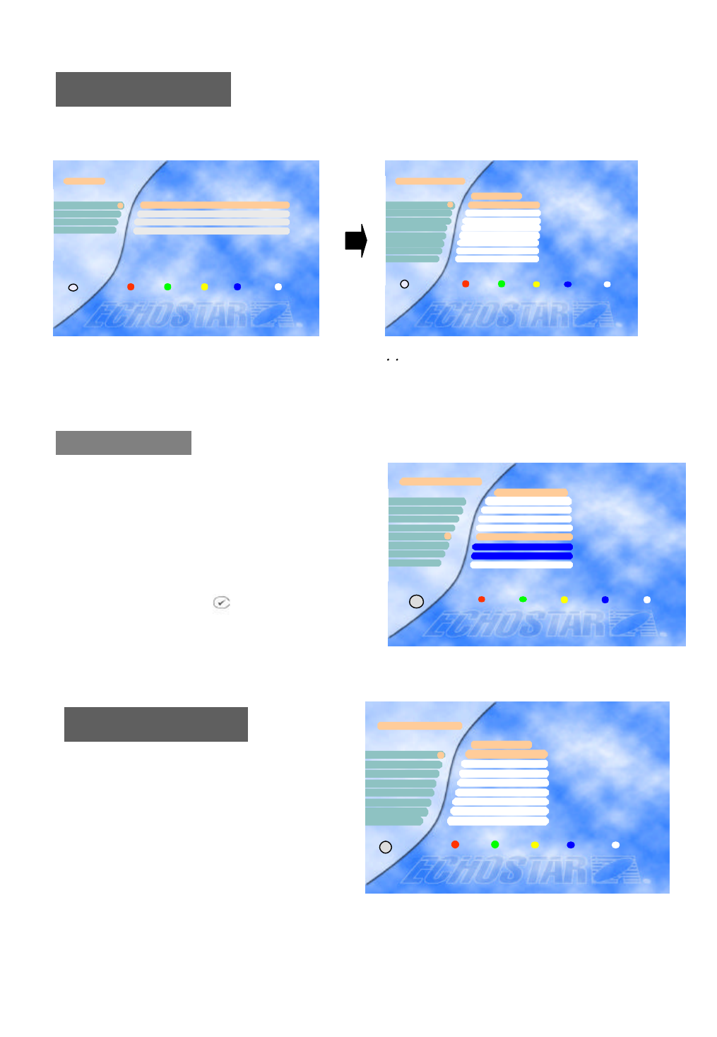
If the Installation & Edit Lock is [ON], you have to input the correct code to ente
r directly into the “Installation” and “Edit” menu..
Press the Red button to lock / unlock the selected c
hannel.
Locked channels will be skipped when scrolling
through the channels.
Note) The color of the highlighted bar turns to red
when it is on a locked channel.
Installation Lock &
Edit Lock
TV Channel Lock
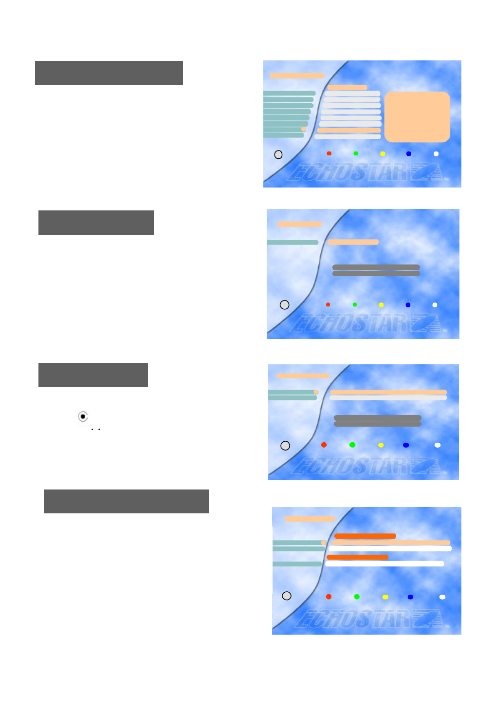
VCR Timer Setting
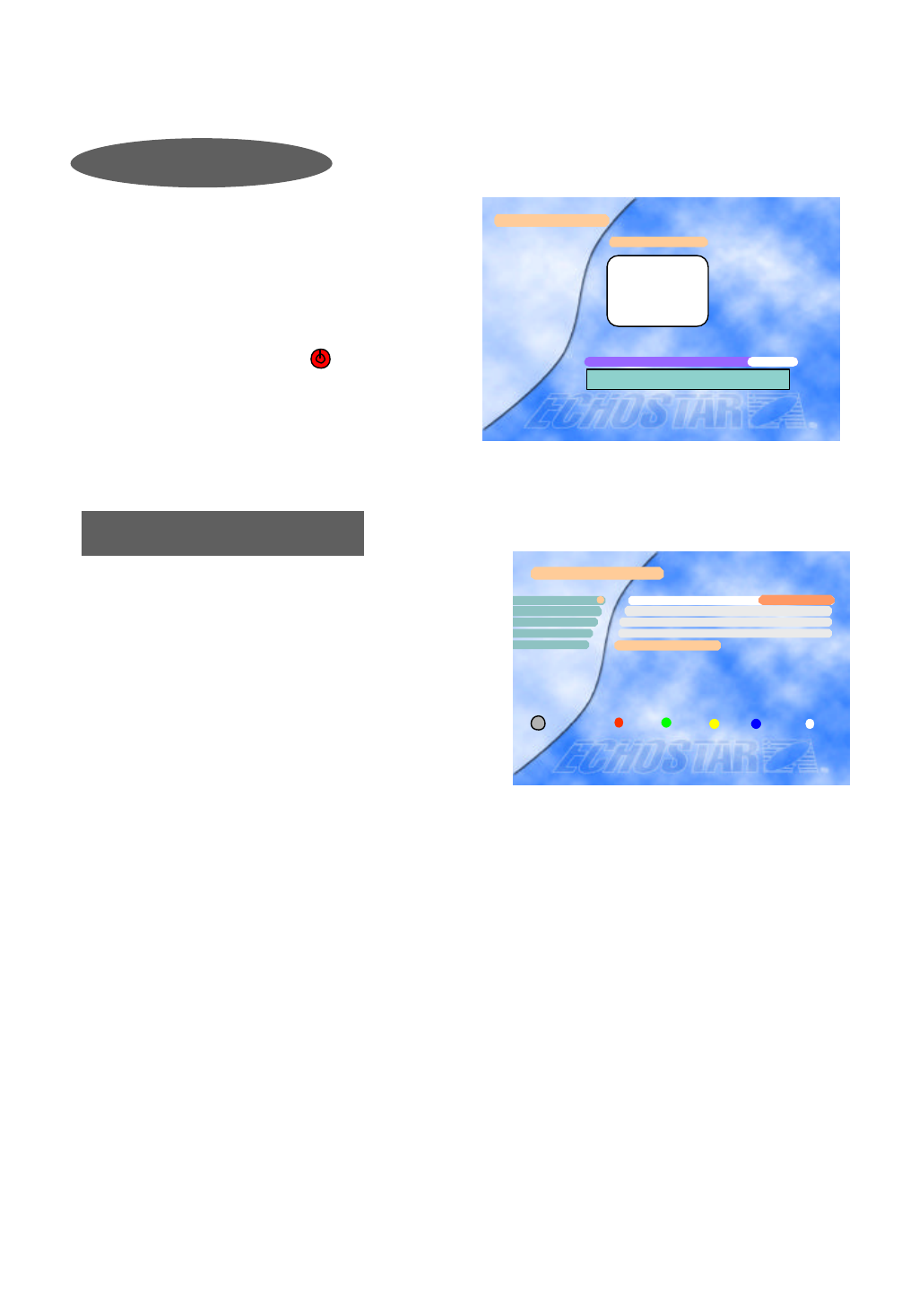
You can edit “VCR Timer Setting” only after you
input all the data in the “Local Time Setting”
Total of 5 events are programmable for your
VCR recording with the EchoStar AD-3000IP
VIACCESS.
If recording “On” is not available, you may check the followings ;
1) Overlapped Events : Check your prior setting for recording. The time for recording(from Start to Stop)
might be overlapped with the new setting.
2) Local Time Setting : Any event which starts earlier than your “Local time Setting” might not work.
Please turn on your VCR to record an event.
VCR Timer
Date(mm/dd/yyyy) ??/??/????
Satellite ASIASAT2
Channel Saudi Ch1
Start Time ( hh:mm) ??:??
Event Number
1
2
43
5
Current Date & Time - Nov./20/1999(Sat.) 20:00
6
87Stop Time (hh:mm) ??:??
Type(O/D/W/M) Once
Recording(On/Off ) OFF
Exit
i
× 1 Ø
If the Receiver Lock is [ON], you have to input the correct code to operate
the receiver.
Receiver Lock
Select an event number from 1 to 5, choose your
wanted Satellite and Channel (only searched
satellites and channels are available to be selected),
input Start time and Stop time (not 12-hours &
AM/PM, but 24 hour system), select your recording
time among O(once) / D(daily) / W(weekly) /
M(monthly).
“On” for recording (On/Off) is only available when
all the data are properly input or selected.
Press the VIEW key to see a thumb nail of the current
channel in this menu.
TV Channel Lock
Voyage
Contact TV
LC I
Canal J
Paris Premere
33
34
36
35
37
38
40
39 DF 1 Info-Kanal
Star Kino
CNN
Lock Unlock Exit
i
TV Channels
23
Edit Radio Channel
Use the same procedure for the Radio Channel
s as used for editing the TV Channels as above.
You can move to the channel that you want to edit by using , keys.
Also you can move to the highlighted bar directly by inputting the channel number.
Edit TV Channel
Edit
Edit TV Channel
Edit Radio Channel
Edit Transponder
Edit Satellite
2
3
4
Exit
i
1
52
51
Edit TV Channel
Paris Premere
Voyage
Contact TV
LC I
50
ASTRA1
Delete Cancel Move Favorite Exit
i
56
55
53
54 Canal J
DF 1 Info-Kanal
Star Kino
CNN
49
Edit Radio Channel
Hit Liste
Blues
Classic Rock
Soft Rock
2
3
4
ASIASAT2
Generation ROC
Love Songs
Dance
REE
5
7
6
8
Delete Cancel Move Favorite Exit
i
1
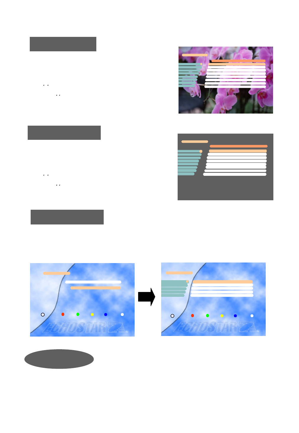
You can create a group of up to 96 channels in the
“Edit TV Channel” or “Edit Radio Channel”
menu. To include a channel in the FAV list, select a
channel and press the blue key on the remote control.
To select a favorite channel from the FAV list, press
the FAV key.
To view a thumb nail representation of the currently
selected channel, press the key on the remote
control.
FAV Channels
Edit TV Channel
Voyage
Contact TV
LC I
Canal J
Paris Premere
53
50
52
51
49
54
56
55 DF 1 Info-Kanal
Star Kino
CNN
ASTRA1
Delete Cancel Move Favorite Exit
i
The “Enter PIN code” Menu is displayed only when the Installation and Edit Lock is set as [ON]. The in
itial code is set as [0000] but you can change it (See “Change PIN code” on page 21).
24
Edit Satellite
To delete a transponder, press the red key when the
highlighted bar is located at the transponder you
want to delete.
To add a transponder, press the blue key.
And then, the “Edit/Add SAT or TP” menu will be displ
ayed, and you can add a transponder in that menu.
Edit Transponder
Select Satellite
To move to another satellite you want to watch, press the
SAT key( ) on the remote control and choose the proper
satellite with , keys.
Press OK to confirm.
Edit Satellite
ASTRA11
Exit Delete Cancel Add SAT
Satellite Name
i
EL WL
Select Satellite
APSTAR2R
ASTRA11
2
Exit
i
EL WL
Edit Transponder
Network(3713H)
Network(3720H)
2
3
4
1Network(3706H)
ASIASAT2
Network(3727H)
Network(3734H)
Network(3764H)
Network(3766V)
5
6
8
Channel List
CHANNEL ONE
Ch.8 - OS Down
Ch.9 - OS Down
Ch.370. Audio
Ch 371. Audio
Ch.372. Audio
Ch.373. Audio
Ch.374. Audio
Ch.375. Audio
Ch.378. Audio
Network(3661H)
Exit
Delete Cancel Add/ TP
i
7
To delete a satellite, press the red key when the
highlighted bar is located at the transponder you
want to delete.
To add a satellite, press the blue key.
And then, “Edit/Add SAT or TP” menu will be displaye
d, and you can add a satellite in that menu.
< Common Interface >
From here you will get access to information and
menus from the CI module(Irdeto, Conax,
Cryptowork, Nagravision and Viaccess encryption).
This information may vary depending on the module.
Please see the documentation delivered together with
your CI module.
Conditional Access
Smart Card Information
Conditional Access
21
Exit
i
3
Slot 2 : Module not installed
Slot 1 : Module not installed
Viaccess Embedded
Common Interface
< Viaccess Embedded >
Insert the Viaccess smart card into the Smart Card slot on the Front Panel. The chip should be faced
upwards.
25
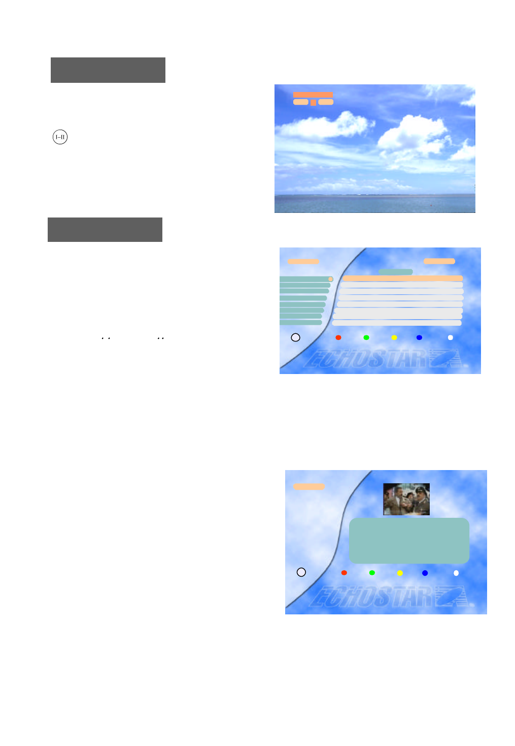
ALT Audio
If more than one audio channel is provided by
the broadcaster on a specific channel, you can
activate the audio mode display by pressing the
key.
L Audio R
1
LR
L Audio R
Guide
While watching or listening to any channel and you
want to know more information regarding the
program shown, press the EPG key on the remote
control to display the “TV Guide” or the “Radio
Guide”. This information may be provided by the
broadcaster. You can move to another channel by
pressing the , keys or the , keys.
Please refer to the function of the keys belows.
Pressing the Yellow(Info) key shows the detailed
information of the program and thumbnail of the
current channel.
TV Guide
RAI1 Linea verde - In ? 11:10~11:55
RAI2 No Information No Time
RAI3 Rai Sport Cavale ? 11:27~12:02
RAIwidescree Wide Screen 11:00~14:00
2
3
4
Radio Next Info Select Exit
i
1
5
6
7
11: 52
Now
RAISPORT sate Rai Sport Sat 11:00~14:00
TEST2RAI No Information No Time
TEST3RAI No Information No Time
1) Red(TV/Radio) key : Switches the “TV Guide” and the “Radio Guide” by pressing this key.
2) Green(Now/Next) key : Switches the program guides of “Now” and “Next”
3) Yellow(Info) key : Shows detailed information of the selected channel.
4) Blue(Select) key : Goes to the viewing mode of the selected channel.
5) White(Exit) key : Exits the TV/Radio Guide
TV Guide
EPG Select Exit
i
RAI1
natura : Linea verde - In diretta dalia natura
Un programma di Sandro Vannucci a cura do
Gian Stefano Snoto produttore esecutivo
Gianoiero Ricci
11:19~11:55
8CNN No Information No Time
26
Note 1) You should execute “Auto Search” after editing the satellite or the transponder.
If “Auto Search” is executed after adding the new transponder, all channels of the added
transponder will be searched and stored automatically.
Note 2) You can add or edit totally of 50 satellites. This includes the pre-programmed satellites.
The receiver has the cap ability to store up to 999 transponders and 5000 channels.
CAUTION: By doing an Auto Channel search you will lose all the data
(e.g. FAV, Lock…) which you have edited.
Advanced Installation
Satellite
Longitude 019.2 °E
Digital/Analog Digital
TP/Signal Quality 0
LNB polarization Vertical
Symbol Rate 0
Channel Name ????????
FEC AUTO
Edit/Add SAT or TP
32
5
6
7
8
4
1
9
10
11
Video PID 0
PCR PID AUTO
Audio PID 0
× ASTRA1 Ø
Edit/Add SAT or TP
C. Advanced Installation
Auto Scan
Auto Sat
Reset(Factory Default)
Edit/Add SAT or TP
Advanced Installation
Edit LNB Local Freq.2
3
4
5
1
Exit
i
Satellite ASTRA1
Longitude 019.2 °E
Digital/Analog
Channel RTL_2
Frequency 11214.00
Polarity Horizontal
Decoder Level 2
C/Ku Ku
Edit/Add SAT or TP
2
5
6
7
8
43
1
9
10
11
Decoder Off
Skew Not set
Low Threshold Off
× Analog Ø
12 Ú More Ú (Audio Setting)
To edit any satellite or transponder, select satellite and transponder to be edited.
You can convert from digital to analog and vice versa, at “Digital/Analog” parameter.
You can change the name of the satellite, transponder, channel name and such.
To change channel name, place highlight bar to “8 Channel Name” and keep pressing
one of either the or keys till it reaches “??? Add ch”.
Then, press the OK key to activate graphic key board and now you can edit the name up to 10-character
length. For some words,, maximum number of the characters is 11. And, mostly 8 characters from
the start shall be shown on the menu when you finish changing name.
You can select the “Advanced Installation” menu
on the “Installation” menu of Main menu by using
the Channel up/down keys (Ù,Ú).
You can edit up to 8 local frequencies by using numeric
keys.
And if you want to save the newly edited frequency, pres
s the OK key.
27
If you want to reset all the data edited, press the Red b
utton twice.
Edit LNB Local Frequency
Reset (Factory Default)
Auto Scan
You can scan analog channels of the chosen satellite automa
tically in this menu.
Press the OK key at the “Start” bar to start channel scannin
g.
By doing a channel scan you will loose the channel names.
This can be redone by going back to factory default.
This function assists end-users to speed up the searching
/storing process. It may be required to fine-tune the video
by adjusting the frequency manually.
Edit LNB Local Frequency
LNB Local Frequency 0..9 × 11300 Ø
Exit
i
Auto Scan ASTRA1
Start
43
1
2Frequency 3000.00
× Horizontal ØPolarity
Channel 000
Exit
i
Reset (Factory Default)
* If you want Factory Reset, press Red button
Reset Cancel Exit
i

28
1. Tuner & channel
Input connector 1 x F type with loop through
Output connector 1 x F type 75 Ohm
Frequency range 950MHz to 2150MHz
Input impedance 75 Ohm
Signal level -25 to -65dBm
IF frequency 480MHz
IF bandwidth 36MHz
LNB power & polarization Vertical +13.5V - +14.5V
Horizontal +17.5V - +18.5V
22kHz tone Frequency 22kHz 2kHz
Amplitude 0.6Vp-p 0.2Vp-p
Demodulation QPSK
Input symbol rate 2 - 32Msps
FEC decoder Convolutional code rate
1/2, 2/3, 3/4, 5/6 and 7/8 with constraint
Length K=7
2. MPEG transport stream A/V decoding
Transport stream MPEG-2 ISO/IEC 13818
Transport stream specification
Profile & level MPEG-2 MP @ ML
Input T/S data rate 90Mbit/S max.
Aspect ratio 4:3, 16:9 with pan vector
Video resolution 720 x 576(PAL), 720 x 480(NTSC)
Audio decoding MPEG-1 Audio Layer 1 & 2, Musicam
Audio mode Stereo, Dual channel, Joint stereo, Mono
Sampling rate 32, 44.1 and 48kHz
3. Memory
Flash memory up to 2 Mbytes
Program DRAM up to 8 Mbytes
EEPROM 2 Kbytes
4. A/V & data in/out
SCART TV x 1, VCR x 1, Decoder x 1
RGB video output TV SCART
0/12V out RCA x 1
CVBS video out RCA x 1, SCART x 2 (TV, VCR)
6. Specifications
Digital Section

29
S/PDIF out RCA x 1
Analog audio out RCA x 2 (L-Ch x 1, R-Ch x 1), SCART x 2 (TV, VCR)
Resolution 16bit DAC
Output level 2Vrms max.
Volume & mute control
Data interface RS232C, Baud Rate 9600 - 115200, 9 Pin D-Sub
5. PCMCIA
Number of Slot 2
Type I, II DVB Common interface standard
6. Conditional Access
Embedded Viaccess 1 Smart Card Reader
7. RF-Modulator
RF-connect 75 Ohm, IEC169-2, male/female
Output Frequency 470MHz to 860MHz
Output channel Ch21 - 69
TV standard PAL D/K, PAL B/G , PAL I
8. Power supply
Input voltage AC90 - 240V, 50/60Hz (Receiver / Positioner)
Type Linear PWM
Power consumption 240W max.(below 7W max. for standby mode)
Protection Separate internal fuse and chassis grounding.
The input shall have lightning or electric shock protection.
9. Physical specification
Size(W x H x D) 370mm x 60mm x 280mm
Weight about 3 Kg
10. Environment
Operating temperature +5ºC - +40ºC
Storage temperature -40ºC - +65ºC
11. Positioner
Satellite position 50
Azimuth & Skew control 6 Push terminal
(M1, M2, M.Pulse, +5V, GND, Skew)
Output power 36VDC, 5A max. (during 5 minutes) (SMPS)
Sensor type Reed or Hall effect switch
Ferrite control 2 Push terminal(+,-)

30
1. RF
Input frequency range 900MHz to 2150MHz
Input impedance 75 Ohms
IF bandwidth 27MHz
IF frequency 479.5MHz
Input signal level -60 to –30dBm
Threshold 6dB Typ. (3dB: low threshold mode, 32 Steps)
2. Audio
Subcarrier tuning range 5.0 to 9.0MHz
De-emphasis J-17 / 50uS / 75uS / Adaptive (Panda-compatible)
IF bandwidth 130kHz / 150kHz / 230kHz / 280kHz / 330kHz / 500kHz
Audio frequency response 20Hz to 15kHz
Output impedance 600 Ohms
Output level 2.0 Vrms Max.
3. Video
Format Invert / Normal (C/ Ku)
Selectable video output
De-emphasis CCIR Recommendation 405-1, 625 lines
Output impedance 75 Ohms
Frequency response 50Hz to 5.0MHz
Output level 1 Vp-p normal
4. Decoder format
Format Base band
De-Emphasized, Unclamped, Un-Filtered,
De-Emphasized, Unclamped, Filtered,
De-Emphasized, Clamped, Filtered
Output impedance 75 Ohms
Output level 1 Vp-p nominal
Analog Section
