Manual
Bentley WiNET Hub User Guide
FAS1505
DOC1037 Revision 0

Document Title UltraClenz, LLC
Page 2
Table of Contents
Revision History ......................................................................................................................................................... 3
Box Contents ............................................................................................................................................................. 4
Overview .................................................................................................................................................................... 4
Installing the Hub ....................................................................................................................................................... 5
Step 1 – Positioning the Chassis ........................................................................................................................... 5
Step 2 – Drilling the Holes ..................................................................................................................................... 5
Step 3 – Placing the Anchors ................................................................................................................................. 5
Step 4 – Mount the Tag to the Wall ....................................................................................................................... 5
Connecting the Hub to the Power Supply ................................................................................................................. 5
Step 1 – Inserting the Screwdriver ......................................................................................................................... 5
Step 2 – Inserting the Power Supply Wires ........................................................................................................... 6
Note: Please ensure proper polarity before plugging the power supply into an electrical outlet. ............................. 6
Configuring the Hub ................................................................................................................................................... 6
Maintenance of the Hub ............................................................................................................................................ 6
Cleaning ................................................................................................................................................................. 6
Certification and Safety Approvals ............................................................................................................................ 7
FCC ........................................................................................................................................................................ 7
Regulations ............................................................................................................................................................ 7
Warranty .................................................................................................................................................................... 8

Document Title UltraClenz, LLC
Page 3
Revision History
Revision Date By Description
0 01/25/11 MJB Initial Release

D
B
O
T
t
D
ocument Ti
B
ox Conte
1
1
2
1
O
verview
T
he FASxxx
x
ransmission
s
tle
nts
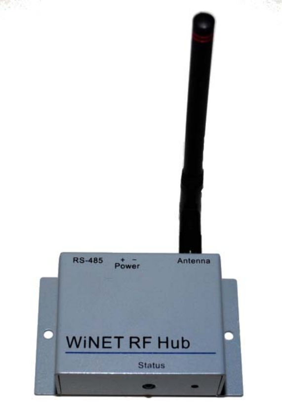
WiNET H
u
Power Su
p
Screws a
n
User’s Gu
i
x
WiNet Hub,
s
from the Wi
N
u
b (with Ante
n
p
ply
n
d Anchors
i
de
when used
N
et Tag to th
e
n
na)
as a compo
n
e
WiNET Gat
Figure 1. –
Wi
Page 4
n
ent of the
W
eway (FASx
x
Wi
NET Network
W
iNET wirele
s
x
xx) (see Fig
u
Topology
s
s monitorin
g
u
re 1).
Ultra
C
g
solution, re
C
lenz, LLC
lays radio
Document Title UltraClenz, LLC
Page 5
Installing the Hub
This procedure will require a small hammer, drill, drill bits, level and a screw driver.
Step 1 – Positioning the Chassis
Place the leveled WiNet Hub on the mounting location to transfer the drill centers.
Step 2 – Drilling the Holes
Drill 2 holes with the proper bit. Use standard bits for dry wall and masonry bits for tile applications.
Step 3 – Placing the Anchors
Gently tap the anchors in place using a hammer.
Step 4 – Mount the Tag to the Wall
Screw the WiNet Hub tightly to the wall.
Connecting the Hub to the Power Supply
This procedure will require a small flat-tip screwdriver.
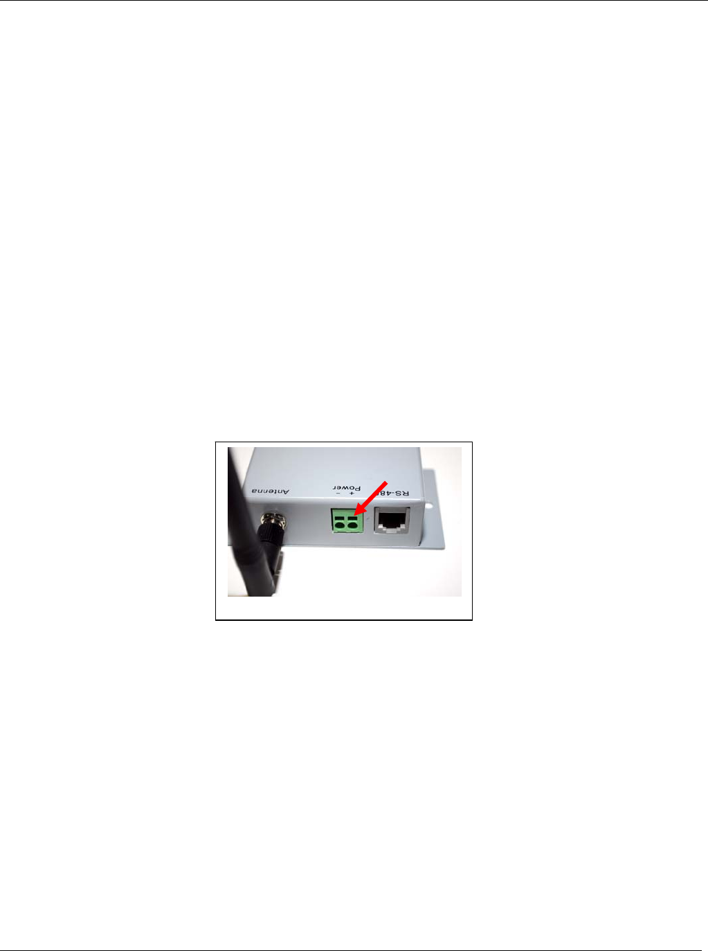
Step 1 – Inserting the Screwdriver
Insert a small flat-tip screwdriver into the rectangular slot of the power connector marked + (positive) on the back
of the hub (see Figure 2). With the tip of the small flat-tip screwdriver, depress the metal tab.
Figure 2
Document Title UltraClenz, LLC
Page 6
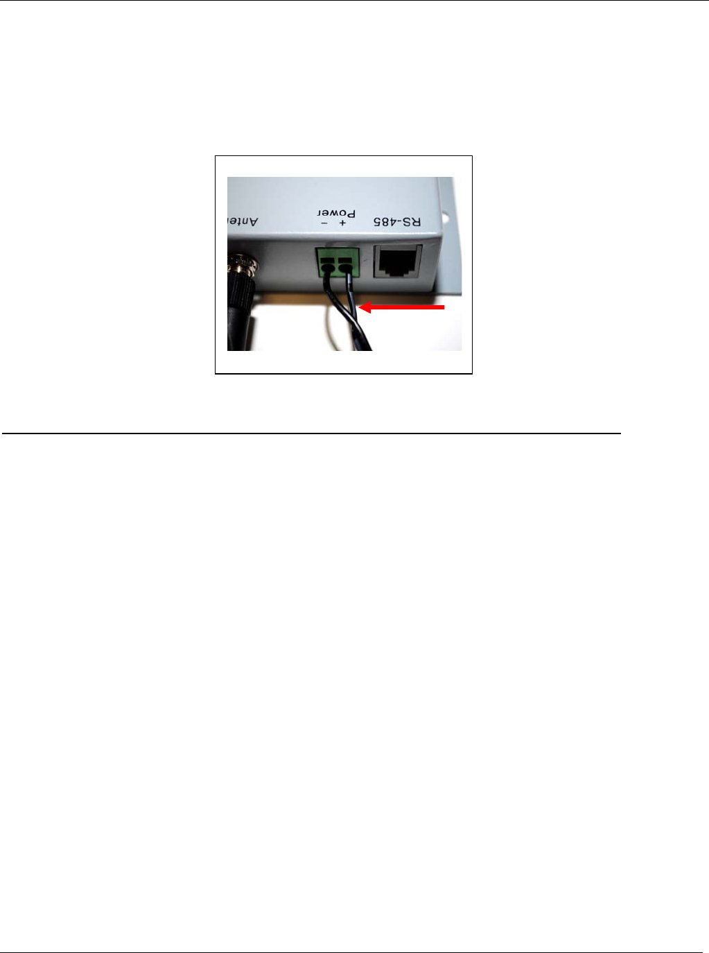
Step 2 – Inserting the Power Supply Wires
With the small flat-tip screwdriver in place, insert the wire with the white stripe on it from the power supply
(positive wire) (see Figure 3) into the circular opening directly beneath the rectangular slot until it stops and pull
out the small flat-tip screwdriver to lock the wire in place. Give the positive wire a slight tug to insure that it is
locked into place. Repeat the process for the rectangular slot of the power connector marked - (negative) on the
back of the hub with the remaining wire.
Note: Please ensure proper polarity before plugging the power supply into an electrical outlet.
Configuring the Hub
The WiNet Hub requires no configuration.
Maintenance of the Hub
Cleaning
The exterior can be cleaned with a NON abrasive detergent and a NON abrasive damp (not wet) sponge or cloth.
The Hub is splash resistant but not water proof.
Figure 3

Document Title UltraClenz, LLC
Page 7
Certification and Safety Approvals
FCC
This equipment has been tested and found to comply with the limits for a Class A digital device, pursuant to Part
15 of the FCC Rules. These limits are designed to provide reasonable protection against harmful interference
when the equipment is operated in a commercial environment. This equipment generates uses and can radiate
radio frequency energy and, if not installed and used in accordance with the instruction manual, may cause
harmful interference to radio communications. Operation of this equipment in a residential area is likely to cause
harmful interference in which case the user will be required to correct the interference at his own expense.
WARNING: Changes or modifications not expressly approved by UltraClenz, LLC could void the user’s authority
to operate the equipment.
Regulations
"Under Industry Canada regulations, this radio transmitter may only operate using an antenna of a
type and maximum (or lesser) gain approved for the transmitter by Industry Canada. To reduce
potential radio interference to other users, the antenna type and its gain should be so chosen that
the equivalent isotropically radiated power (e.i.r.p.) is not more than that necessary for successful
communication."
"This device complies with Industry Canada license-exempt RSS standard(s). Operation is subject
to the following two conditions: (1) this device may not cause interference, and (2) this device
must accept any interference, including interference that may cause undesired operation of the
device."

Document Title UltraClenz, LLC
Page 8
Warranty
This device is warranted against defective materials and workmanship for one year from the date of delivery.
Equipment covered by this warranty will be repaired or replaced in the United States and Canada, WITHOUT
CHARGE, except for shipping and handling, by our Factory Service Center.
When returning equipment for warranty service, you must first call your distributor’s Warranty Service
Department for your Return Merchandise Authorization Number (RMA), the RMA must be on your return label,
also the shipping charges must be pre-paid and a copy of your receipt must be enclosed.
This warranty covers all defects incurred from normal use of the equipment and does not apply in the following
cases:
a. Loss or damage to the equipment due to abuse, mishandling, accident or failure to follow mounting
instructions.
b. If the equipment is defective as a result of leaking batteries.
c. If the equipment has been serviced or modified by someone other than our authorized agents.
THE AFOREMENTIONED IS IN LIEU OF ALL WARRANTIES, EXPRESSED OR IMPLIED, INCLUDING BUT
NOT LIMITED TO, ANY WARRANTY OF MERCHANTABILITY OR OF FITNESS FOR ANY PARTICULAR
PURPOSE. IN NO EVENT SHALL THE VENDOR BE LIABLE FOR CONSEQUENTIAL, INCIDENTAL,
INDIRECT OR SPECIAL DAMAGES OR LIABILITY, TRANSPORTATION, INSTALLATION OR SUBSTITUTION
COSTS, DELAYS, OR FOR ANY OTHER DAMAGES, COSTS, OR EXPENSES INCURRED, IRRESPECTIVE
OF HOW THEY OCCUR. THIS WARRANTY SHALL NOT EXTEND TO ANY OTHER PERSON OTHER THAN
THE ORIGINAL PUCHASER OF THIS EQUIPMENT OR THE PERSON FOR WHOM IT WAS PURCHASED AS
A GIFT.
This warranty gives you specific legal rights, and you may also have other rights, which may vary from state to
state. This warranty is given with respect to equipment purchased in the United States.
This warranty is for the touch-free soap dispenser only, and excludes any representation or warranty with regard
to any soap, lotion, solution or other liquid used in the dispenser. Use of improperly formulated soaps, lotions,
solutions or other liquids could result, amongst other things, in damage to the dispenser, and/or leakage, which in
turn could create conditions leading to personal injury. In no event shall the vendor be liable for any damage or
injury caused by any soaps, lotions, solutions or other liquids used in the dispenser.
Patent Pending