Ecolab FAS1506 Gateway User Manual DOC1038r0x
UltraClenz LLC. Gateway DOC1038r0x
UserManual.wiki
>
Ecolab
>
FAS1506 User Manual
Manual
Navigation menu
Upload a User Manual
Namespaces
Wiki Guide
HTML
PDF
Info
Views
User Manual
Discussion / Help
Navigation
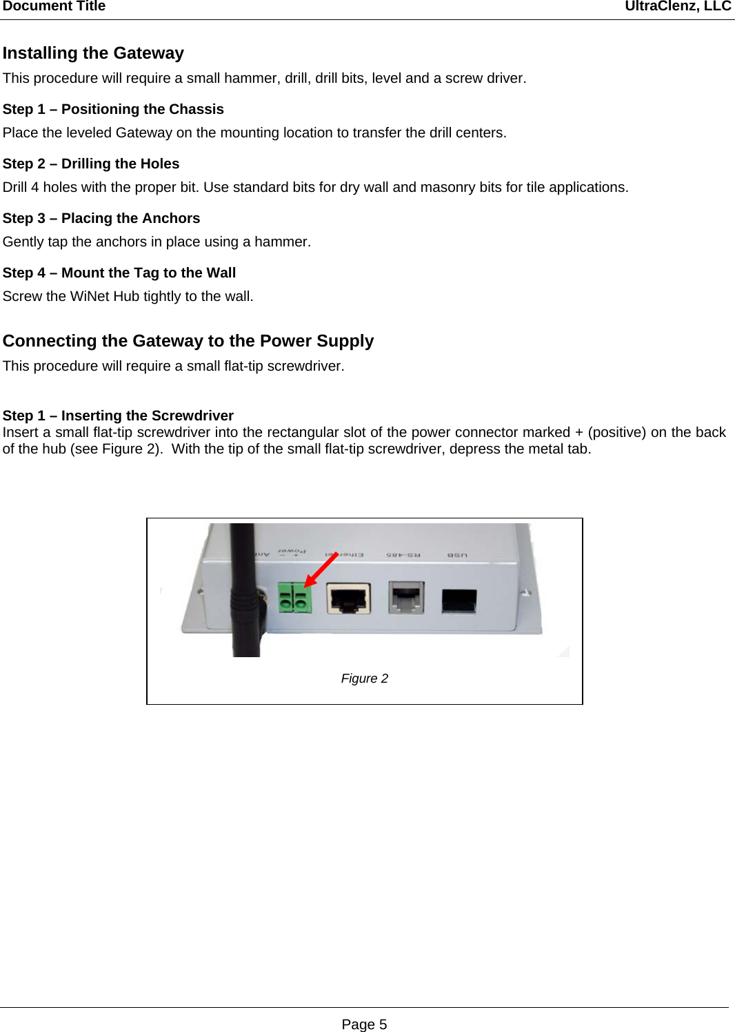
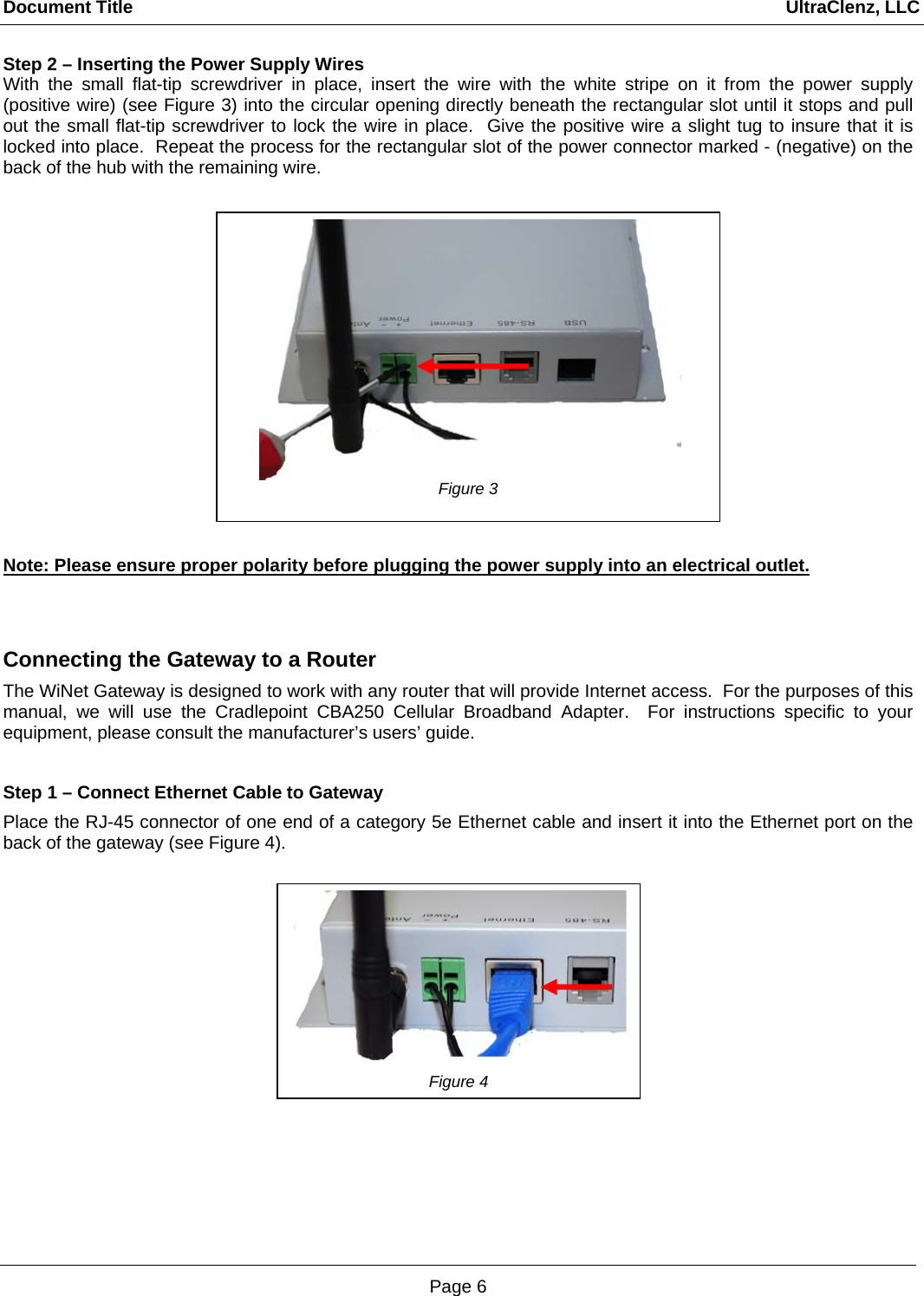
![Document Title UltraClenz, LLC Page 9 Step 2 – Configuring the Gateway through HyperTerminal. a) Set the time on the Gateway by typing ‘T’ followed by the date/time group using the following syntax; t yyyy-mm-dd hh:mm:ss [enter] (example: t 2011-01-18 20:32:40) b) With the Gateway connected to the Router (see Figures 5 and 6) type ‘C’ [enter] to show the Gateway’s current network configuration c) Type “CD 1” [enter] to enable Dynamic Host Configuration Protocol (DHCP). This protocol with have your Gateway receive all network IP addresses from the Router. d) Type ‘B’ [enter] to display the backend server configuration. To set the correct backend server IP address, type BS nnn [enter] where nnn is the IP address of the backend server. (example: BS 111.111.111.1) e) Type ‘G’ [enter] to toggle the gateway events monitoring to ON. This allows you to see events as they occur in real time on HyperTerminal. f) Type ‘M’ [enter] to toggle radio traffic monitoring to OFF. This will eliminate additional messages on the screen and make the event messages more understandable. A summary of all common commands is shown in figure 9. Gateway will receive both Dispense Events and Heartbeat Events. A Dispenser Event occurs whenever a radio-equipped dispenser on the Gateway’s network is activated. A Heartbeat Event occurs at regular intervals and serves as a message from a device on the network to the Gateway to announce that it is still operational. The events will be displayed in HyperTerminal as shown in Figure 10. Figure 9 Figure 10 – Blue text added for informational purposes](https://usermanual.wiki/Ecolab/FAS1506/User-Guide-1727152-Page-9.png)