Ecolab FAS1511 PSS Bed Beacon User Manual FCC Part 15
UltraClenz LLC. PSS Bed Beacon FCC Part 15
Ecolab >
Manual

3998 FAU Blvd. Suite 310 Boca Raton, FL 33431 Tel: 561-961-5585 Fax: 561-961-5587
Certification Exhibit
FCC ID: Z9O-FAS1511
IC: 10060A-FAS1511
FCC Rule Part: 15.209, 15.231, 15.249
IC Radio Standards Specification: RSS-210
ACS Project: 11-2104
Manufacturer: UltraClenz, LLC
Models: FAS1511-00, FAS1511-01, FAS1511-02,
FAS1511-03, FAS1511-04
User Manual
Patient Safeguard System (PSS)
Bed Beacon User’s Guide
DOC1048 Revision 1
UltraClenz, LLC

Patient Safeguard System – Bed Beacon User’s Guide UltraClenz, LLC
Page 2
Table of Contents
Revision History ......................................................................................................................................................... 3
1.0 Introduction to the System .................................................................................................................................. 4
2.0 System Components .......................................................................................................................................... 4
3.0 Patient Bed Beacon ............................................................................................................................................ 5
4.0 Adjusting the Patient Bed Beacon Communication Range ................................................................................. 6
5.0 How the System Works ...................................................................................................................................... 7
6.0 Installing the System .......................................................................................................................................... 9
6.1 Patient Bed Beacon Installation ....................................................................................................................... 9
6.2 Patient Bed Antenna ..................................................................................................................................... 11
Appendix A - System Component Care and Maintenance ...................................................................................... 12
Cleaning the Components ................................................................................................................................... 12
Handling the Bed Beacon .................................................................................................................................... 12
Battery Replacement ........................................................................................................................................... 12
Appendix B - Certification and Safety Approvals ..................................................................................................... 13
FCC ...................................................................................................................................................................... 13
Industry Canada ................................................................................................................................................... 13
Warranty .................................................................................................................................................................. 14

Patient Safeguard System – Bed Beacon User’s Guide UltraClenz, LLC
Page 3
Revision History
Revision Date By Description
0 03/14/12 MES Initial Release
1 08/09/12 DLS Corrected TOC and replaced FCC class A statement with class B statement

Patient Safeguard System – Bed Beacon User’s Guide UltraClenz, LLC
Page 4
1.Healthcare Worker (HWC) Badge
FAS1509
1.0 Introduction to the System
The Patient Safeguard System (PSS) was designed to help Healthcare Workers (HCW) protect their patients from
the unintentional spread of pathogens. This is achieved by providing a tool to remind HCWs to perform hand
hygiene when the opportunities are presented. Hand hygiene opportunities, in a patient care environment, are
defined as instances when hand hygiene should be performed to reduce or eliminate a patient’s exposure to
harmful or even deadly pathogens carried on the HCW’s hands. These patient care hand hygiene opportunities
are described in detail by the World Health Organization’s (WHO) “Your 5 Moments for Hand Hygiene”.
PSS software provides HCWs with real-time feedback when hand hygiene opportunities occur and will also
provide a warning when hand hygiene opportunities are missed or ignored. The real-time data can be viewed at a
designated computer terminal or a tablet running the PSS application software. PSS may also be configured to
monitor and assess the hand hygiene performance of HCWs on either a group or individual basis. By assessing
how well a HCW recognizes and engages in hand hygiene opportunities, the HCW will receive feedback that lets
them know how well they’re doing. This feedback can then be used to establish performance benchmarks and
goals. HCW performance can then be tracked over time, measured against these benchmarks and goals to
assess overall compliance to identify specific areas where improvement is needed. Ultimately, the purpose of
PSS is to provide HCWs with a tool that allows them to improve upon, and then maintain, high levels of hand
hygiene performance, thus providing a safer environment for their patients and themselves.
2.0 System Components
PSS consists of 4 basic components; a HCW badge, a soap/sanitizer dispenser beacon, a patient bed beacon
and a patient bed antenna. These components work together to form a system that will allert HCWs when hand
hygiene needs to occur or alarm them when hand hygiene failed to occur.
3.Patient Bed Beacon
FAS1511
2.Soap/Sanitizer Dispenser Beacon
FAS1510
Patient Safeguard System – Bed Beacon User’s Guide UltraClenz, LLC
Page 5
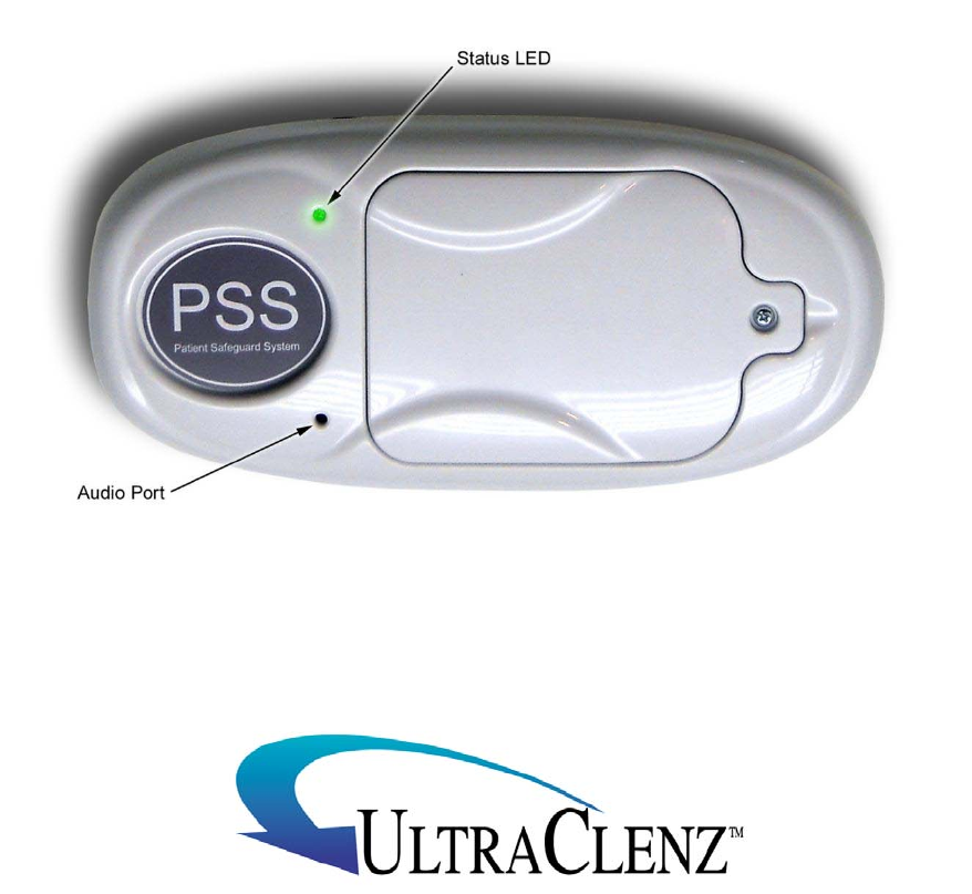
3.0 Patient Bed Beacon
The bed beacon, via its detachable patient bed antenna, creates an invisible boundary around the patient’s bed.
This boundary defines the patient’s “space” and is called the patient zone. When a HCW crosses this boundary
and enters the patient zone, the HCW is now considered to be in contact with the patient. The HCW’s badge will
then communicate with the bed beacon. The bed beacon will then reply and the badge will immediately change
its hand hygiene state. For example, if the HCW’s badge is in the sanitary state (green flashing LED) it will then
change to a cautionary state (yellow flashing LED ) to indicate that a compliant patient contact event has
occurred. A thorough explanation of badge states and state changes is provided later in this document.
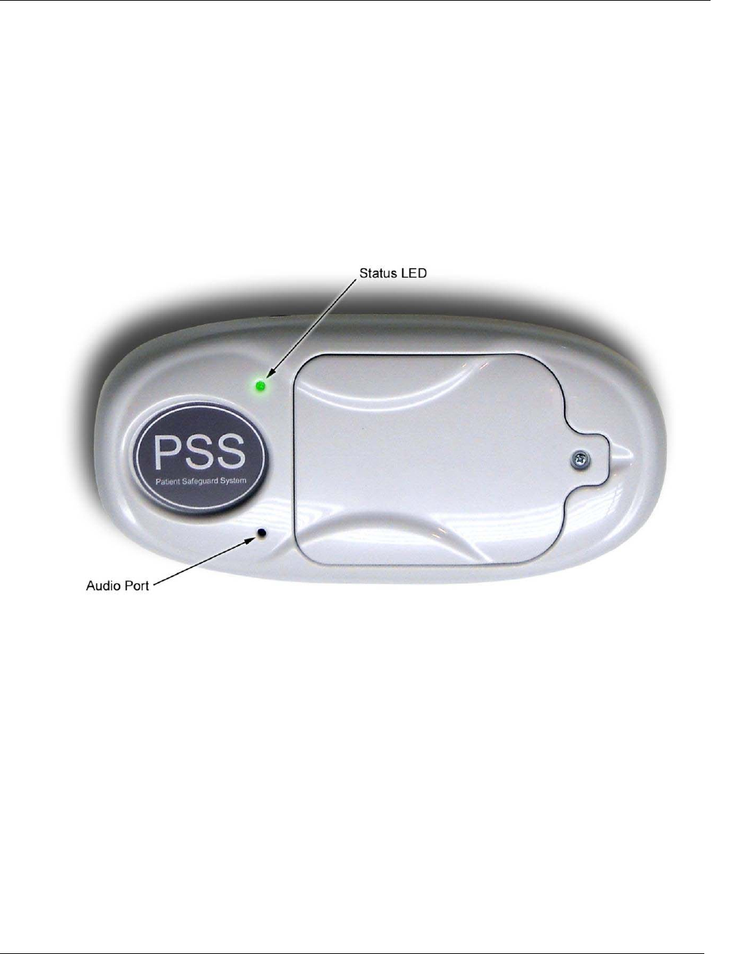
The bed beacon provides both audio and visual alerts to indicate that it has successfully communicated with a
HCW’s badge. Upon successful communication, the status LED will flash green one time followed by a two tone
chime (see Figure 5).
Patient Safeguard System – Bed Beacon User’s Guide UltraClenz, LLC
Page 6
4.0 Adjusting the Patient Bed Beacon Communication Range
The patient bed beacon range of communication is adjusted during installation to maximize communication with
the Healthcare Worker (HCW) badge. To adjust the communication range, remove the battery cover located on
the front of the beacon using a #2 Phillips screwdriver (see Figure 3). Note: the battery cover has a retaining ring
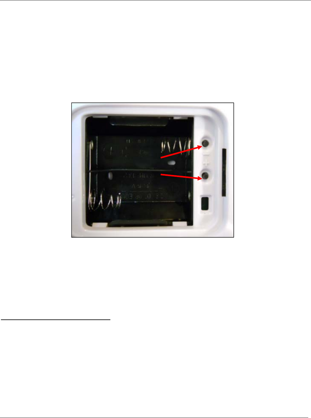
to prevent the screw from being detached. After the cover has been removed, the beacon communication range is
adjusted by repeatedly pushing either the “+” increment or the “–“ decrement range buttons (see Figure 4) to
achieve the desired range. The total adjustable range of each beacon is 1 to 32 increments between the lowest
and the highest setting. Each push of either the “+” or “–“ button will produce an audible beep indicating one
increment up or down. When the lowest or the highest setting is reached, four audible beeps will be heard. To
reset a beacon’s range back to the factory default setting, push and hold both the “+” and the “–“ buttons down, at
the same time, until four audible beeps are heard. The factory default range setting for the Bed beacon is 24.
Replace the battery cover when the adjustment is complete.
There may be circumstances which require a beacon’s range to be adjusted, after the initial installation, to
properly communicate with a badge. Examples of why bed beacon’s range may need to be adjusted are
explained below.
Case for Bed Beacon Range Adjustment
1. Two beds with bed beacons in one room.
2. Two beds with bed beacons in separate but adjacent rooms separated by a wall.
In both cases, the range of communication of a given bed beacon may overlap or interfere with a nearby bed
beacon. If this occurs, the HCW’s badge may communicate with a nearby bed beacon instead of the intended
bed beacon. This miscommunication will result in the system reporting contact with the wrong patient.. To
eliminate the possibility of miscommunication, the range of bed beacons in close proximity may be decreased, at
any time, to insure that a HCW’s badge will communicate with the intended bed beacon. This is accomplished by
removing the beacon’s battery cover and pressing the “–“ button to shorten the range. Continue pressing the “-“
button until the desired range and thus proper communication is achieved.
Figure 6 - Patient Bed Beacon Increment "+" and Decrement "-" Communication Range Buttons
Increment "+"
Decrement "–"

Patient Safeguard System – Bed Beacon User’s Guide UltraClenz, LLC
Page 7
5.0 How the System Works
When a Healthcare Worker (HCW) begins their shift, they will attach an assigned badge to their clothing in a
location above the waist that is clearly visible to HCW as well as others. The badge will be dormant with no
blinking LED visible. This is normal because the badge will go into a “sleep” state to conserve battery power
when not in use for a period of 30 minutes or more.
The first thing the HCW will do, after attaching their badge, is wash or sanitize their hands. The dispenser beacon
attached to the soap/sanitizer dispenser will communicate with the badge when the dispenser is activated. Even
though the badge is in a sleep state, it is always listening and the dispenser beacon’s communication will wake it
up. The badge will produce 3 quick beep tones with the second tone being lower in pitch than the first or third
tones. This indicates successful communications between the badge and the dispenser beacon. The badge will
then be set to the sanitary or clean state with the green LED blinking about once every 1.5 seconds. The HCW is
now ready to begin their normal work routine.
When the badge is set to the sanitary state, the badge starts an internal timer. If there is no interaction between
the HCW and a dispenser or patient bed, the timer will continue to increment. If the timer reaches 20 minutes, the
badge will automatically change from the sanitary state to the cautionary state. When this transition occurs, the
badge will produce 2 quick beep tones with both having the same pitch. This indicates to the HCW that the badge
has automatically changed state. The badge’s yellow LED will then blink about once every 1.5 seconds. The
cautionary state does not imply a violation of hand hygiene protocol. In this case, it is indicating to the HCW and
anyone else able to see the badge’s yellow LED that the HCW has not washed or sanitized their hands for at
least 20 minutes and that they may not approach a patient until doing so.
If the HCW does approach a patient while in the cautionary state, this event will be considered a violation of hand
hygiene protocol and the badge will change from the cautionary state to the warning state. The badge will
produce 3 quick beep tones with the second tone being lower in pitch than the first or third tones. This indicates
successful communications between the badge and the bed beacon located within the patient zone. The badge’s
red LED will then blink about once every 1.5 seconds. Immediately after changing to the warning state, the badge
will produce a rapid burst of 4 tones with each having a different pitch. This will be repeated 4 more times over
the next 20 seconds and will indicate to the HCW that they must wash/sanitize their hands immediately.
If the HCW approaches a patient while in the sanitary state, the badge will change to the cautionary state. The
badge will produce 3 quick beep tones with the second tone being lower in pitch than the first or third tones. This
indicates successful communications between the badge and the bed beacon located within the patient zone.
The badge’s yellow LED will then blink about once every 1.5 seconds. The cautionary state does not imply a
violation of hand hygiene protocol. In this case, it is indicating to the HCW and anyone else able to see the
badge’s yellow LED that the HCW is currently in contact with a patient or has had contact with a patient within the
last 5 minutes.
While the HCW is inside the patient zone, their badge will remain in the cautionary state. When the HCW leaves
the patient zone, the badge starts an internal timer. If there is no interaction between the HCW and a dispenser,
after leaving the patient zone, the timer will continue to increment. If the timer reaches 5 minutes, the badge will
automatically change from the cautionary state to the warning state. When this transition occurs, the badge will
produce 2 quick beep tones with both having the same pitch. This indicates to the HCW that the badge has
automatically changed state. Immediately after changing to the warning state, the badge will produce a rapid
burst of 4 tones with each having a different pitch. This will be repeated 4 more times over the next 20 seconds
and will indicate to the HCW that they must wash/sanitize their hands immediately.
A HCW may contact a patient, leave the patient zone briefly and then re-contact the same patient without
washing/sanitizing their hands. However, the HCW may not re-contact the patient without first using a
soap/sanitizer dispenser if they are outside of the patient zone for more than 1 minute. As long as the HCW
remains inside the patient zone, their badge will remain in the cautionary state. When the HCW leaves the patient
zone, the badge starts an internal timer. If there is no interaction between the HCW and a dispenser, after leaving
the patient zone, the timer will continue to increment. If the HCW then reenters the patient zone and the internal
timer has not reached 1 minute, the badge will remain in the cautionary state and the internal timer will be reset.
However, if the HCW reenters the patient zone and the internal timer has reached or passed 1 minute, the badge

Patient Safeguard System – Bed Beacon User’s Guide UltraClenz, LLC
Page 8
will change to the warning state. The badge will produce 3 quick beep tones with the second tone being lower in
pitch than the first or third tones. This indicates successful communications between the badge and the bed
beacon located within the patient zone. The badge’s red LED will then blink about once every 1.5 seconds.
Immediately after changing to the warning state, the badge will produce a rapid burst of 4 tones with each having
a different pitch. This will be repeated 4 more times over the next 20 seconds and will indicate to the HCW that
they must wash/sanitize their hands immediately.
A HCW may not go from one patient zone to another without washing/sanitizing in-between. While a HCW is in a
patient zone, their badge will be in the cautionary state. When they leave the patient zone, their badge will remain
in the cautionary state for up to 5 minutes beyond which time their badge will automatically change to the warning
state or until they wash/sanitize at which time their badge will then change to the sanitary state. If the HCW
leaves a patient zone and then enters a different patient zone without first interacting with a soap/sanitizer
dispenser, the badge will change from the cautionary state to the warning state. The badge will produce 3 quick
beep tones with the second tone being lower in pitch than the first or third tones. This indicates successful
communications between the badge and the bed beacon located within the patient zone. The badge’s red LED
will then blink about once every 1.5 seconds. Immediately after changing to the warning state, the badge will
produce a rapid burst of 4 tones with each having a different pitch. This will be repeated 4 more times over the
next 20 seconds and will indicate to the HCW that they must wash/sanitize their hands immediately.
Patient Safeguard System – Bed Beacon User’s Guide UltraClenz, LLC
Page 9
6.0 Installing the System
6.1 Patient Bed Beacon Installation
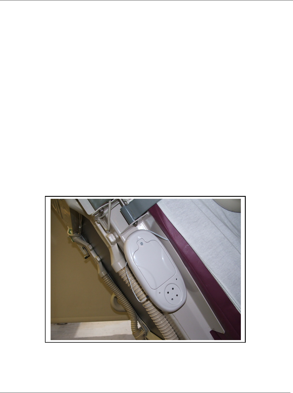
The patient bed beacon can be mounted on the wall near the head of the patient’s bed or directly to the frame
of the bed itself. It is also possible to mount the bed beacon to a gurney, wheelchair or other transportable
device that may be occupied by a patient. In the case of a patient bed located in a patient room, it may be
best to mount the bed beacon to the wall so that if the bed is removed and replaced, the bed beacon will
remain and will always be associated with the same patient room regardless of what bed is currently present
(see Figure 6).
6.1.1 Mount Using Tape
To mount the bed beacon on a metal surface or a transportable device, double sided tape or Velcro tape
may be the best choice. Double sided tape and Velcro tape may also be used for wall mounting if
desired. Velcro tape will have the advantage of making the bed beacon removable from the mounting
surface. For both double sided tape and Velcro tape, a minimum of a single strip, at least 3 inches long,
should be used.
To insure the best adhesion of the tape, make sure that the mounting surface of both the bed beacon and
the object the bed beacon will be mounted to is clean and free of dirt and oil. A soft cloth dampened with
isopropyl alcohol will work well to clean both surfaces. Most tape adhesives require about 24 hours of
curing. Avoid installing batteries into the bed beacon until the tape’s adhesive has had a chance to cure.
Otherwise, the extra weight may cause the bed beacon to detach from the surface it has been mounted
to.
Figure 6. Bed Beacon Mounted on Patient Bed
Patient Safeguard System – Bed Beacon User’s Guide UltraClenz, LLC
Page 10
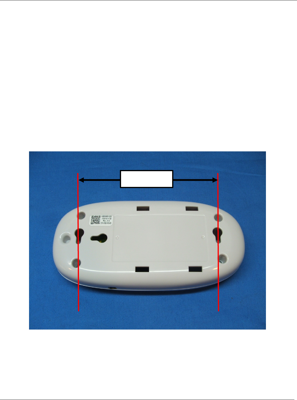
6.1.2 Mount Using Screws
The rear surface of the bed beacon has two keyhole shaped openings that are 511 16
inches on center.
Locate the position and height on the wall where the bed beacon will be mounted. Mark the location for
the first mounting screw. Then, measure left or right 511 16
inches and mark the location of the second
mounting screw. Use a level to verify that the screw locations lineup parallel to the floor.
The keyhole openings will accept #6 or #8 screws and it is advisable to use properly sized wall anchors.
Using a correctly sized drill bit, drill a hole in the wall for each mounting screw at the locations marked.
Be aware that the wall at the head of a patient bed may contain gas lines. Insert the wall anchors into the
wall and then install the screws. Both screws will need a gap between the base of the screw’s head and
the surface of the wall. Start with about 1/8 of an inch.
Attach the bed beacon to the wall by lining up the large portion of the keyhole openings with the mounting
screw heads and push the bed beacon flush against the wall. Then, gently slide the bed beacon towards
the floor until the smaller portion of the keyhole openings make contact with the shaft of both mounting
screws.
If the bed beacon is not in tight contact with the wall, remove the bed beacon and tighten both mounting
screws a little more to reduce the gap between the screw’s head and the surface of the wall.
5 11/16 Inches
Patient Safeguard System – Bed Beacon User’s Guide UltraClenz, LLC
Page 11
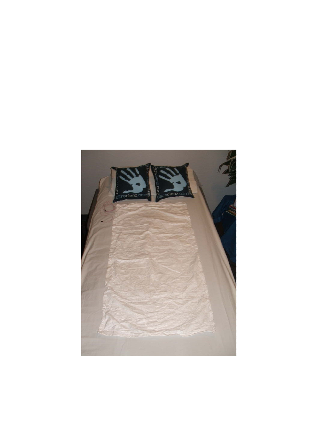
6.2 Patient Bed Antenna
The bed antenna is placed on the patient’s bed either under the mattress pad or under the mattress. It is
made from a thin sheet of Tyvek® with the antenna screen printed on its surface. The antenna is cleanable,
disposable or recyclable. It may be replaced and discarded whenever the patient’s bed linens are changed.
The bed beacon uses the bed antenna to create the barrier that defines the patient zone around the patient’s
bed.
The bed antenna is attached to the bed beacon via a small cable and breakaway connector. The breakaway
connector will allow the bed antenna to disconnect from the bed beacon when the bed is moved without
damage to the bed beacon. However, it is best to manually disconnect the connector before moving the
patient bed.
Figure 7. Bed Antenna shown on top of bed for illustration purposes.
Patient Safeguard System – Bed Beacon User’s Guide UltraClenz, LLC
Page 12
Appendix A - System Component Care and Maintenance
Cleaning the Components
The bed beacon should be cleaned by wiping with a soft cloth. A mixture of 90% water and 10% chlorine (bleach)
or water and mild detergent (dish soap) may be used. The cloth should be damp but not wet. Only the exterior of
the component may be cleaned. Do not attempt to clean any interior surface of this component as this will
damage the component’s circuitry. Do not use abrasive cleaners or cleaning products in aerosol cans as they will
damage the component’s finish.
Handling the Bed Beacon
The bed beacon is an electronic device and should be handled with care. Like other electronic devices such as
cell phones, the bed beacon must be protected from extreme heat, cold and moisture. Avoid handling the bed
beacon with wet hands or exposing it to rain. Avoid dropping or tossing the bed beacon. The shock can damage
the beacon’s sensitive internal electronics.
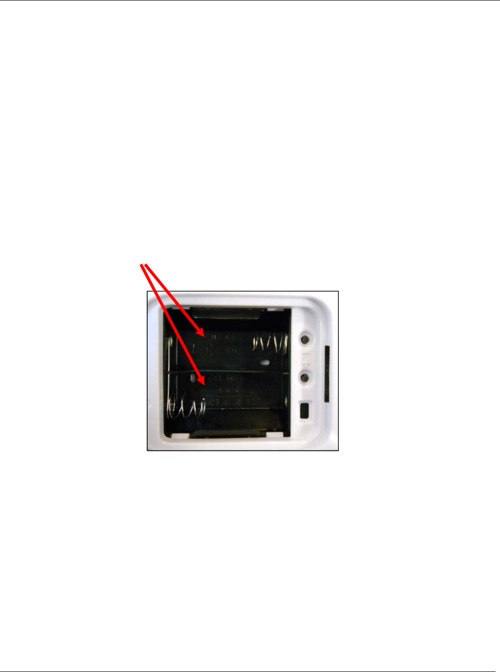
Battery Replacement
Bed Beacon is powered by 2 “D” Cell Batteries
Patient Safeguard System – Bed Beacon User’s Guide UltraClenz, LLC
Page 13
Appendix B - Certification and Safety Approvals
FCC
NOTE: This equipment has been tested and found to comply with the limits for a Class B digital device, pursuant
to Part 15 of the FCC Rules. These limits are designed to provide reasonable protection against harmful
interference in a residential installation. This equipment generates, uses, and can radiate radio frequency energy
and, if not installed and used in accordance with the instructions, may cause harmful interference to radio
communications. However, there is no guarantee that interference will not occur in a particular installation. If this
equipment does cause harmful interference to radio or television reception, which can be determined by turning
the equipment off and on, the user is encouraged to try and correct the interference by one or more of the
following measures:
• Reorient or relocate the receiving antenna.
• Increase the separation between the equipment and receiver
• Connect the equipment into an outlet on a circuit different from that to which the receiver is connected.
• Consult the dealer or an experienced radio/TV technician for help.
WARNING: Changes or modifications not expressly approved by UltraClenz, LLC could void the user’s authority
to operate the equipment.
Industry Canada
Under Industry Canada regulations, this radio transmitter may only operate using an antenna of a type and
maximum (or lesser) gain approved for the transmitter by Industry Canada. To reduce potential radio interference
to other users, the antenna type and its gain should be so chosen that the equivalent isotropically radiated power
(e.i.r.p.) is not more than that necessary for successful communication.
This device complies with Industry Canada license-exempt RSS standard(s). Operation is subject to the following
two conditions: (1) this device may not cause interference, and (2) this device must accept any interference,
including interference that may cause undesired operation of the device.

Patient Safeguard System – Bed Beacon User’s Guide UltraClenz, LLC
Page 14
This radio transmitter (IC: 10060A-FAS1511) has been approved by Industry Canada to operate with the antenna
types listed below with the maximum permissible gain and required antenna impedance for each antenna type
indicated. Antenna types not included in this list, having a gain greater than the maximum gain indicated for that
type, are strictly prohibited for use with this device.
Le présent émetteur radio (IC: 10060A-FAS1511) a été approuvé par Industrie Canada pour fonctionner avec les
types d'antenne énumérés ci-dessous et ayant un gain admissible maximal et l'impédance requise pour chaque
type d'antenne. Les types d'antenne non inclus dans cette liste, ou dont le gain est supérieur au gain maximal
indiqué, sont strictement interdits pour
l'exploitation de l'émetteur.
Magnetic Loop Antenna
Printed-F antenna, 6.3 dBi
Wire monopole antenna, -2.3 dBi
Warranty
This device is warranted against defective materials and workmanship for one year from the date of delivery.
Equipment covered by this warranty will be repaired or replaced in the United States and Canada, WITHOUT
CHARGE, except for shipping and handling, by our Factory Service Center.
When returning equipment for warranty service, you must first call your distributor’s Warranty Service
Department for your Return Merchandise Authorization Number (RMA), the RMA must be on your return label,
also the shipping charges must be pre-paid and a copy of your receipt must be enclosed.
This warranty covers all defects incurred from normal use of the equipment and does not apply in the following
cases: a. Loss or damage to the equipment due to abuse, mishandling, accident or failure to follow mounting
instructions.
b. If the equipment is defective as a result of leaking batteries.
c. If the equipment has been serviced or modified by someone other than our authorized agents.
THE AFOREMENTIONED IS IN LIEU OF ALL WARRANTIES, EXPRESSED OR IMPLIED, INCLUDING BUT
NOT LIMITED TO, ANY WARRANTY OF MERCHANTABILITY OR OF FITNESS FOR ANY PARTICULAR
PURPOSE. IN NO EVENT SHALL THE VENDOR BE LIABLE FOR CONSEQUENTIAL, INCIDENTAL,
INDIRECT OR SPECIAL DAMAGES OR LIABILITY, TRANSPORTATION, INSTALLATION OR SUBSTITUTION
COSTS, DELAYS, OR FOR ANY OTHER DAMAGES, COSTS, OR EXPENSES INCURRED, IRRESPECTIVE
OF HOW THEY OCCUR. THIS WARRANTY SHALL NOT EXTEND TO ANY OTHER PERSON OTHER THAN
THE ORIGINAL PUCHASER OF THIS EQUIPMENT OR THE PERSON FOR WHOM IT WAS PURCHASED AS
A GIFT.
This warranty gives you specific legal rights, and you may also have other rights, which may vary from state to
state. This warranty is given with respect to equipment purchased in the United States.
Patent Pending