Ecolink Intelligent Technology PIRZB1 Comcast Xfinity Home Motion Sensor User Manual 1
Ecolink Intelligent Technology, Inc. Comcast Xfinity Home Motion Sensor 1
User Manual
MODEL URC4470BC0-X-R FLAT PIR 1
ZigBee Home Automation 1.2
Wireless Digital Pet Immune PIR Detector
Installation Instructions
1. INTRODUCTION
The URC4470BC0-X-R is a microprocessor-controlled wireless digital PIR detector supported by ZigBee HA 1.2.
The detector’s features are as follows :
Up to 15 meters (49.2 ft)
Uniform Detection
White light immunity
Enhanced Pet immunity up to 85Ibs
Enhanced false alarm rejection
In normal mode, after detection, the detector goes to sleep to save battery power. It wakes again (reverts to the ready state) if there is no
subsequent detection throughout the following 3-minute period.
Temperature compensation.
Tamper protection.
For UL installations: The detector is for use with UL listed control unit only. Pet immunity has not been evaluated by UL.
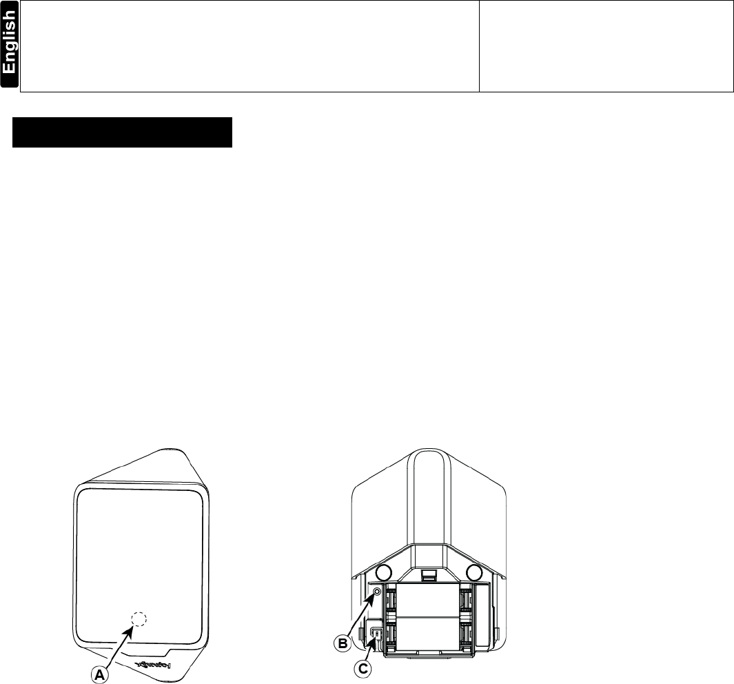
Figure 1 - MP-841
A. Red LED
B. Green LED
C. Tamper Switch

2 MODEL XXXX FLAT PIR
2. SPECIFICATIONS
Detector Type
Two - Dual element low-noise pyroelectric sensor
Optical Data
18 parabolic mirrors for long range
18 parabolic mirrors for close range
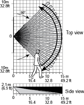
Max. Coverage
15 x 15 m, (49.2 x 49.2 ft) / 90°
Pet Immunity
Up to 38 kg (85 lb)
ELECTRICAL
Internal Batteries
Two 3V Lithium batteries, type CR-123A. For UL installations, use Panasonic only
Nominal Battery Capacity
1400 mAh per battery
Battery Life (with LED on)
Typically over 5 years
Note: Inability to connect with wireless network, or wireless link quality no higher than 20% may
significantly reduce the expected battery life.
Battery Power Test
Performed immediately upon battery insertion and during each transmission to the panel
FUNCTIONAL
Alarm Period
3 seconds
Visual Indications
Red LED lights for about 3 seconds upon transmission of alarm & tamper messages and upon motion
detection in the walk test mode only.
Red LED flashes during the power-up stabilization period, or after restoring (pressing) the tamper switch.
Red LED does not light upon transmissions of supervision messages or alarm detection after termination
of walk test mode.
“Sleep” Timer
After an alarm, the detector will go into low power mode and not check for motion for 3 minutes. After 3
minutes the detector will check for motion. If there is still motion, it will NOT transmit. If after 3 minutes
there is no motion it will transmit to the panel. Timer disabled in the walk test mode
WIRELESS
Supported Network
ZigBee H.A 1.2
Frequency
2.405 – 2.480 Ghz as per IEEE 802.15.4
Tamper Alert
Reported when a tamper event occurs and in any subsequent message, until the tamper switch is
restored
PFD
Signaling at 5 minute intervals
Check in
Signaling at 27 minute intervals
MOUNTING
Height
2.9 m (7.5 ft).
Installation Options
Surface or corner
ENVIRONMENTAL
RFI Protection
>20 V/m up to 1000 MHz
Operating Temperatures
-10°C to 50°C (14°F to 122°F
Storage Temperatures
-20°C to 60°C (-4°F to 140°F)
COMPLIANCE WITH STANDARDS
USA
CFR 47 part 15
ANSI/UL 639
PHYSICAL
Size (H x W x D)
83 x 61 x 42 mm (3.27 x 2.4 x 1.66”)
Weight (with battery)
90 g (3.17 oz)
Color
White
MODEL URC4470BC0-X-R FLAT PIR 3
3. INSTALLATION
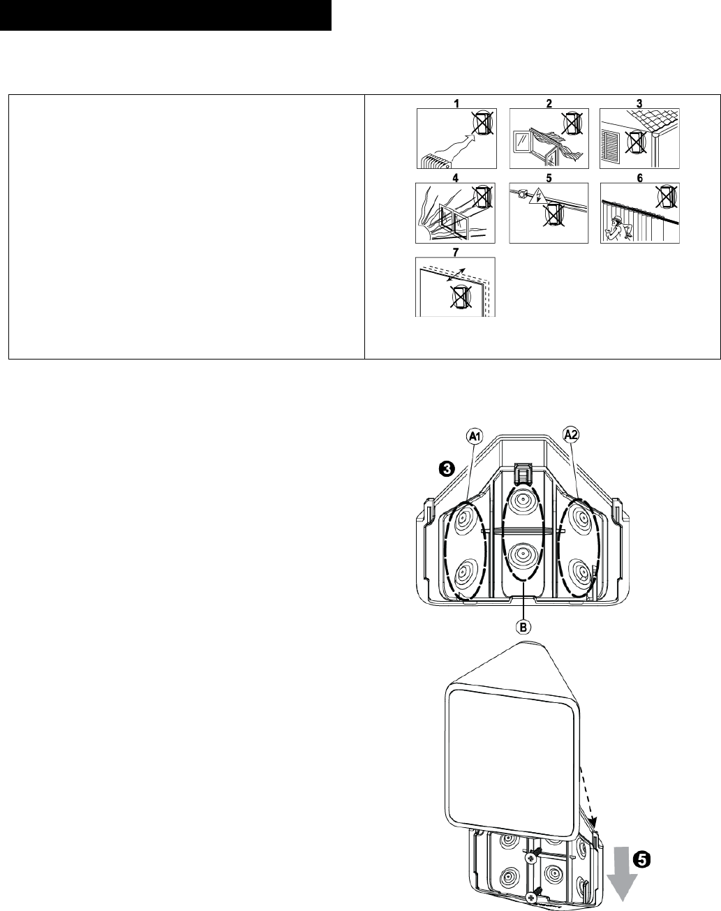
3.1 General Guidance
1. Keep away from heat sources.
2. Do not expose to air drafts.
3. Do not install outdoors.
4. Avoid direct sunshine.
5. Keep wiring away from power cables.
6. Do not install behind partitions.
7. Mount on solid stable surface.
Figure 2. General Guidelines
3.2 Installation Procedure
Figure 3 – Opening the Unit
Figure 4 – Bracket Mounting
Figure 5 – Removing activation strip
Figure 6 – Mounting Detector on Bracket
4 MODEL XXXX FLAT PIR
1. Push in the direction of the arrow shown in the drawing to
separate the detector from the bracket.
2. Mount the bracket on the wall.
3. Install new batteries.
-OR-
If batteries are already installed, pull the activation strip.
4. Mount the detector on the bracket by sliding it downward until
a click is heard.
Note: It is recommended to wait about 1 minute after battery removal, before inserting the new battery.
Caution! Risk of explosion if battery is replaced by an incorrect type. Dispose of used battery according to the manufacturer's instructions
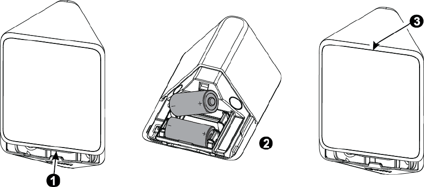
3.3 Replacing the Batteries
1. Press upward to separate the detector from the bracket.
2. Replace the batteries.
3. Put back the detector on the bracket.
Figure 7 – Replacing Batteries
3.4 Activating and Pairing the Detector
To pair the detector to the Touchscreen (control panel), you must set it to pairing mode.
1. First set the Touchscreen (panel) to pairing mode and then the detector.
2. To activate, pull the activation strip that protrudes from the back of the detector (see Figure 5).
3. The green LED (see Figure 1) blinks 3 times every 5 seconds (repeated up to 20 times) to indicate that the detector is searching for the
Touchscreen (control panel).
Note: If detector pairing is not successful during the searching process – by pressing the tamper switch – the searching process will restart.
4. Complete the pairing procedure on the Touchscreen (control panel) (see the pairing instructions in the Touchscreen / control panel’s installation
guide).
Note: Pairing should be performed before installation.
(Detector installation will have a good link with panel, if RSSI indicated on the Panel higher than -70BM and LQI stronger than 250. If values of
RSSI and LQI are lower, change Detector placement)
3.5 Rebooting the Detector
You can reboot the detector, as follows.
1. Remove the battery cover.
2. Remove BOTH batteries for 5 seconds
3. Re-insert both batteries
4. Close the battery cover.
MODEL URC4470BC0-X-R FLAT PIR 5
3.6 Defaulting the Detector
CAUTION! The defaulting process removes the device from the network and enables re-pairing.
Separate the detector from the bracket to remove both batteries. (see Figure 7).
1. Press and hold down the detector’s tamper switch.
2. Insert one of the two batteries into the detector while observing battery polarity.
3. Release the tamper switch within 4 seconds (the LED blinks 3 times every 5 seconds).
4. To re-pair the detector, follow the instructions in section 3.4.
3.7 Walk Testing
Walk across the far end of coverage pattern in both directions. The LED should light for 2-
3 seconds each time your motion is detected.
Important! Instruct the user to walk test at least once a week to verify proper function of
the detector.
Note: Upon battery insertion or closing the cover (which results in closing the tamper
switch) the LED flashes for 1 minute and the detector goes into walk-test mode
for 15 minutes. In walk-test mode the LED lights upon every motion detection.
After 15 minutes the detector automatically enters normal mode in which the LED
will not blink after detection.
Figure 8 - Coverage Pattern Walk-Test
COMPLIANCE WITH STANDARDS
FCC
This device complies with Part 15 of the FCC Rules and RSS-210 of Industry and Science Canada. Operation is subject to the following two
conditions: (1) This device may not cause harmful interference, and (2) this device must accept any interference received, including interference
that may cause undesired operation.
This device complies with Industry Canada license-exempt RSS standard(s). Operation is subject to the following two conditions: (1) this device
may not cause interference, and (2) this device must accept any interference, including interference that may cause undesired operation of the
device.
Le présent appareil est conforme aux CNR d'Industrie Canada applicables aux appareils radio exempts de licence. L'exploitation est autorisée
aux deux conditions suivantes : (1) l'appareil ne doit pas produire de brouillage, et (2) l'utilisateur de l'appareil doit accepter tout brouillage
radioélectrique subi, même si le brouillage est susceptible d'en compromettre le fonctionnement.
FCC ID: XQC-PIRZB1
IC: N/A
WARNING! Changes or modifications to this unit not expressly approved by the party responsible for compliance could void the user’s authority to
operate the equipment.
This equipment has been tested and found to comply with the limits for a class B digital device, pursuant to part 15 of the FCC Rules. These limits
are designed to provide reasonable protection against harmful interference in a residential installation. This equipment generates, uses and can
radiate radio frequency energy and if not installed and used in accordance with the instructions, may cause harmful interference to radio
communications. However, there is no guarantee that interference will not occur in a particular installation. If this equipment does cause harmful
interference to radio or television reception, which can be determined by turning the equipment off and on, the user is encouraged to try to correct
the interference by one or more of the following measures:
Reorient or relocate the receiving antenna.
Increase the separation between the equipment and receiver.
Connect the equipment into an outlet on a circuit different from that to which the receiver is connected.
Consult the dealer or an experienced radio/TV technician for help.
In order to maintain compliance with FCC regulations, shielded cables must be used with this equipment. Operation with non-approved equipment
or unshielded cables is likely to result in interference to radio and TV reception. The user is cautioned that changes and modifications made to the
equipment without the approval of manufacturer could void the user's authority to operate this equipment.

6 MODEL XXXX FLAT PIR
To satisfy RF exposure requirements, this device and its antenna must operate with a separation distance of at least 20 cm from all persons and
must not be co-located or operating in conjunction with any other antenna or transmitter.
USA: CFR 47 Part 15, UL 639