Edelbrock 68713 Users Manual 68712, TES For 82 87 Camaro & Firebird With LG 4 Low Output 305 CID V8.qxp
68712 68712
2015-02-06
: Edelbrock Edelbrock-68713-Users-Manual-537965 edelbrock-68713-users-manual-537965 edelbrock pdf
Open the PDF directly: View PDF ![]() .
.
Page Count: 3
Catalog #68712, 68713
©2006 Edelbrock Corporation
Page 1 of 3 Brochure #63-68712
Rev. 6/06 - DA/mc
TUBULAR EXHAUST SYSTEM
For 1982-1987 Camaro & Firebird
with LG-4 (Low Output) 305 C.I.D. V8 Engine
Catalog #68712, #68713
INSTALLATION INSTRUCTIONS
Please study these instructions carefully before installing your new
Tubular Exhaust System
(TES). If you have any questions, please contact our
Technical Hotline at : 1-800-416-8628 from 7 am - 5pm, Monday-Friday, Pacific Standard Time or e-mail us at Edelbrock@Edelbrock.com.
TUBULAR EXHAUST SYSTEM: These components are designed as a system to improve the exhaust efficiency of the GM 305 LG-4 V8 engine. A
performance gain can be expected by the installation of the system. This system requires no welding for installation and retains all O.E.M.
emissions equipment.
Suggested Tools Needed for Installation: This vehicle has metric fasteners.
❑ 3/8” ratchet socket set with extensions and universal 13mm and 15mm swivel sockets
❑Combination set of open-end wrenches
❑ Jackstands, screwdrivers, pliers, crescent wrench, etc.
❑Liquid penetrant, (GM #1052627) anti-seize compound (GM #5613695)
SPECIAL NOTICE: This Edelbrock Tubular Exhaust System has received an Executive Order number (E.O.#) from the California Air Resources Board
(C.A.R.B.) making it legal for street use in all 50 states. To assist you with emission equipment certification, we have included a silver fan shroud
decal to help testing personnel verify the this part is a legal replacement on the vehicle for which it is cataloged. The adhesive-backed decal should
be affixed next to the existing emission and engine specifications decal. Do not cover any part of your original emission decal.
WARNING: The use of "Thermal Wrap" or any aftermarket coating process will void the warranty on your Edelbrock Tubular Exhaust Systems.
Those products can cause excessive heat and moisture buildup resulting in corrosion and failure of the system.
NOTE: High temperature spark plug wires and boots are recommended to withstand heat from T.E.S.
IMPORTANT NOTE:
Proper installation is the responsibility of the installer. Improper installation will void warranty and may result in poor
performance and engine or vehicle damage.
KIT CONTENTS
Catalog #68712 (Ceramic-Coated), #68713 (Ti-Tech Coated)
Qty. Description
❑1Header left side #25-9331 (#68712)
❑1Header right side #25-9332 (#68712)
❑1Header left side #25-9003 (#68713)
❑1Header right side #25-9004 (#68713)
❑1Extension pipe left side #25-9503
❑1Extension pipe right side #25-9504
❑ 1Umpco clamp; 3/8” I.D.
❑ 1Umpco clamp; 1-5/8” I.D.
❑ 1Hex nut; 10-32
❑ 1Hex capscrew; 10-32 x 1”
❑ 1Star washer; 3/16” internal
❑ 2Tube spacer; 5/8” x 1.53”
❑ 1Tube spacer; 5/8” x .72
❑ 2Donut gaskets; 2-1/4”
Qty. Description
❑ 1Flange connector
❑ 1U-Muffler clamp; 2-1/4”
❑ 1O2 Sensor pigtail wire; 12”
❑ 2Chevy V8 port gaskets
❑ 1Thermo wrap; 2” x 6”
❑ 1Safety wire; 8”
❑2Hex capscrews; 3/8” 16 x 2”
❑2Header bolts; 3/8” - 16 x 3”
❑16 Split lock washers; 3/8”
❑4Flat washers; 3/8”
❑ 12 Header bolts; 3/8” - 16 x 1”
❑ 2Hex cap screws; 3/8” - 16 x 3”
❑ 1O2 Sensor plug (if needed)
❑ 4Hardened washers; 3/8”

Catalog #68712, 68713
©2006 Edelbrock Corporation
Page 2 of 3 Brochure #63-68712
Rev. 6/06 - DA/mc
• DISASSEMBLY
1. Disconnect battery negative cable from battery.
2. Raise vehicle and support with jackstands.
3. The use of penetrating oil when removing and the use of anti-
seize compound when installing nuts and bolts will prevent the
possibility of broken or stripped nuts and bolts.
4. Making sure converter is cool, remove the catalytic converter.
5. Lower vehicle to the ground.
• DISASSEMBLY LEFT SIDE
1. Remove air cleaner system (note position of line and hose
connections).
2. Disconnect A.I.R. (air injection reactor) hose from exhaust
manifold.
3. Remove air conditioner rear support bracket (if air conditioning
is applicable).
4. Remove power steering support bracket (if power steering is
applicable).
5. Disconnect spark plug wires and remove spark plugs.
6. Remove O2 sensor, being careful not to rupture or destroy the
unit.
WARNING: Do not clean this unit in any cleaning solvents and
do not rupture wire.
7. Disconnect temperature sensor wire at cylinder head.
8. Remove temperature sensor wire support bracket from valve
cover bolt and lay wire back over engine.
9. Remove bolts and exhaust manifold from top side.
10. Disconnect steering column connector and lower slip tube
down to steering box. CAUTION: Do not turn steering wheel or
front wheels while this system is disconnected.
• DISASSEMBLY RIGHT SIDE
1. Disconnect A.I.R. injection hose from exhaust manifold and
catalytic converter tube.
2. Disconnect electrical connector and vacuum hoses from A.I.R.
diverter valve assembly (note position of hose and electrical
connections).
3. Remove A.I.R. pump feed hose from diverter valve assembly.
4. Remove nut from diverter valve support bracket at exhaust
manifold and loosen lower alternator pivot bolt, then remove
diverter valve assembly.
5. Disconnect spark plug wires and remove spark plugs.
6. Remove dipstick and tube from engine.
CAUTION: Do not damage tube.
7. Remove bolts and exhaust manifold from top side.
8. At this time, clean exhaust flange surfaces on cylinder heads.
• ASSEMBLY LEFT SIDE
1. Install T.E.S. flange gasket and one 3/8-16 x 1" bolt and lock
washer at rearmost bolt hole (leave bolt loose enough to accept
T.E.S.).
2. Install left side T.E.S. manifold from top side.
3. Install all but the front two bolts and washers on left side (do
not tighten at this time).
4. Re-install rear power steering support bracket. Do not tighten
at this time.
5. Re-install rear A/C support bracket with bolts, lock washers and
spacers supplied.
6. Align all parts and tighten left side bolts and nuts at this time.
7. Re-connect steering column coupler.
INSTALLATION INSTRUCTIONS
WARNING: Make sure coupler bolt is tight and check to see
that steering wheel is in same orientation as prior to
disassembly.
8. Form brake lines to clear T.E.S. pipes.
9. Re-install spark plugs and reconnect wires left side.
10. Re-install temperature sensor wire support bracket and
reconnect wire to temperature sensor.
11. Re-install O2 sensor. Use anti-seize on threads of sensor and
torque to 30 ft./lbs. Re-route O2 sensor wire from wire loom to
O2 sensor (use O2 sensor extension lead supplied) making sure
all wires are clear of exhaust system.
• ASSEMBLY RIGHT SIDE
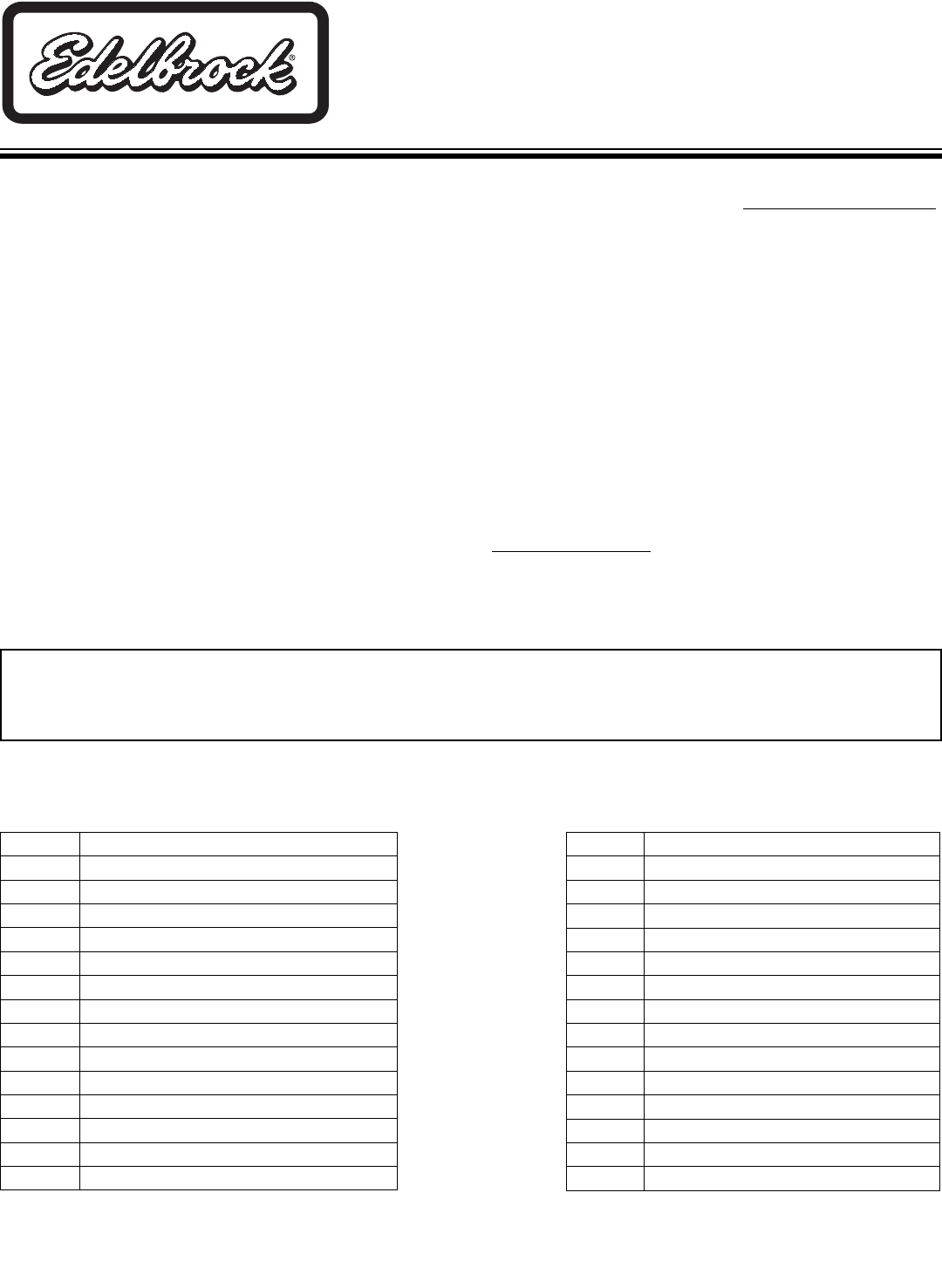
1. Remove fuel line bracket bolts on side and top of frame (two
bolts) right side.
2. Pull lines away from frame approximately 1" and place any
spacer between lines and frame to hold away.
3. Soak thermo wrap supplied in water, this will make it easy to
form.
4. Form thermo wrap around fuel lines as shown in
Figure 1.
5. With thermo wrap in place, wrap wire around at each end to
hold in place.
6. Remove spacer.
7. Replace bolts and tighten both clamps.
8. Install T.E.S. flange gasket and one 3/8" - 16 x 1" bolt, lock
washer and flat washer at rearmost bolt hole (leave bolt loose
enough to accept T.E.S).
9. Install right side T.E.S. manifold from top side concurrently with
dipstick tube.
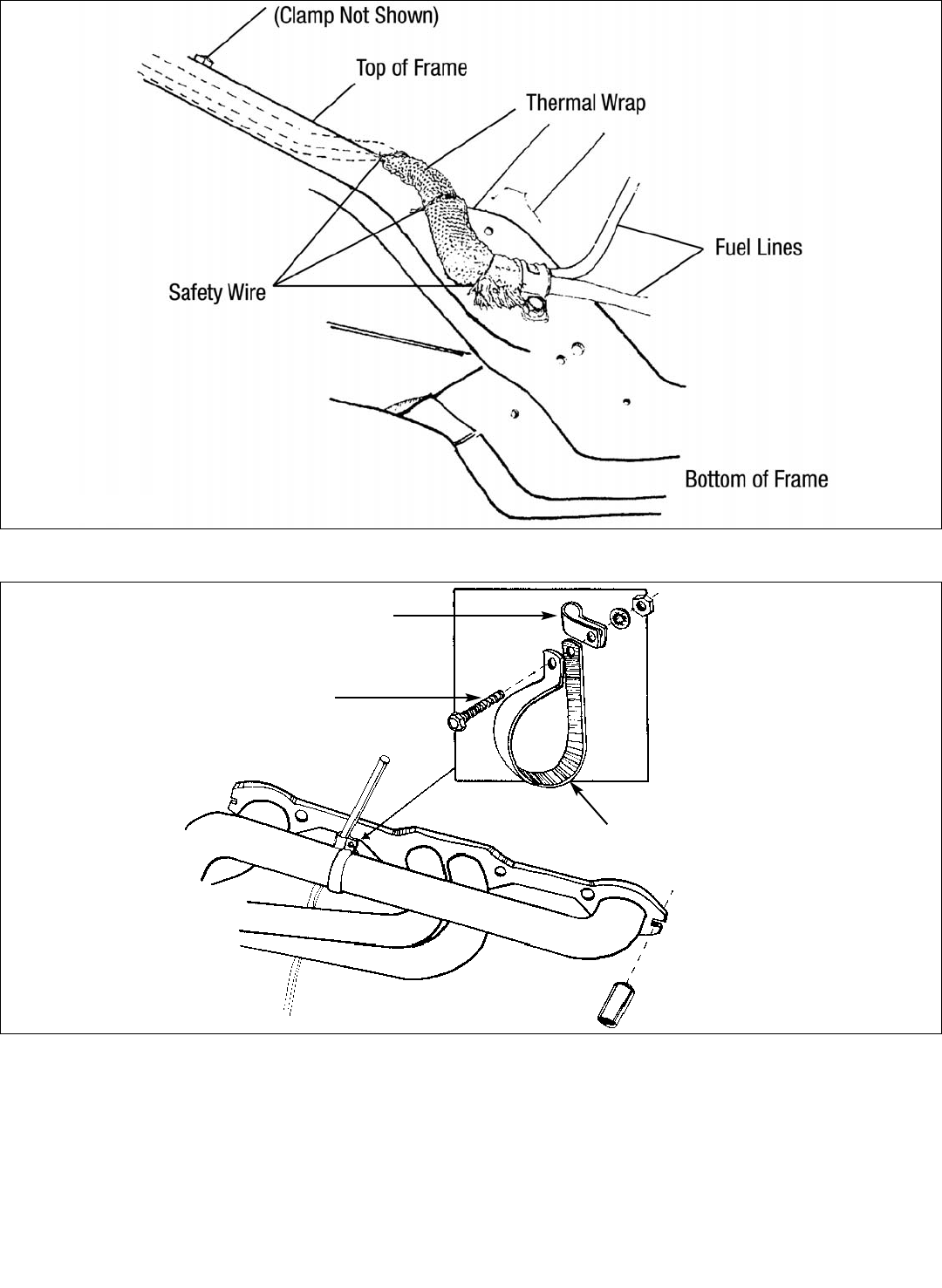
10. Install remaining bolts, lockwashers, dipstick and tube clamps
(see Figure 2)
. Do not tighten bolts at this time.
11. Re-install O.E.M. front stud bolt with spacer (supplied). Align all
parts and tighten all right side bolts at this time.
12. Re-install spark plugs and reconnect wires.
13. Re-install diverter valve assembly in front O.E.M. stud bolt and
tighten.
14. Re-connect electrical connections and vacuum lines to diverter
valve assembly.
15. Remove A.I.R. Check valves from O.E. manifolds and re-install
them on T.E.S. Re-connect all injection hoses.
16. Raise vehicle and support with jackstands.
• CROSSOVER PIPE ASSEMBLY
1. Assemble both lower pipes. Do not clamp tight at this point.
2. Rotate E.F.E. valve 180° from its original position (the
diaphragm will now be facing to the rear of vehicle).
3. Install crossover pipe assembly on vehicle with four 3/8" bolts,
lock and flat washers and gaskets supplied. Do not tighten at
this time.
4. Form A.I.R. injection tube to catalytic converter. Align and
tighten all bolts and clamps at this time.
• LOWER VEHICLE TO THE GROUND
1. Connect negative cable to battery. At this point, it would be a
good idea to look everything over and make sure nothing was
missed in assembly.
2. Start vehicle, bring up to normal operating temperature and
check for possible leaks.
3. Turn engine off and let cool. Tighten all bolts again.
Catalog #68712, 68713
©2006 Edelbrock Corporation
Page 3 of 3 Brochure #63-68712
Rev. 6/06 - DA/mc
Edelbrock Corporation, 2700 California St., Torrance, CA 90503
Tech Line: 1-800-416-8628
E-Mail: Edelbrock@Edelbrock.com
Small Umpco Clamp
10-32 Capscrew, Nut, and Washer
Large Umpco Clamp
.720” Spacer
Fig. 2
Fig. 1
