Edgecore Networks SMC2891WAN 802.11a/b/g/n Outdoor Dual Band Wireless Access Point User Manual installation guide
Edgecore Networks Corporation 802.11a/b/g/n Outdoor Dual Band Wireless Access Point installation guide
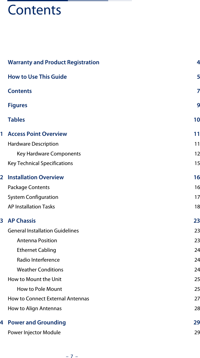
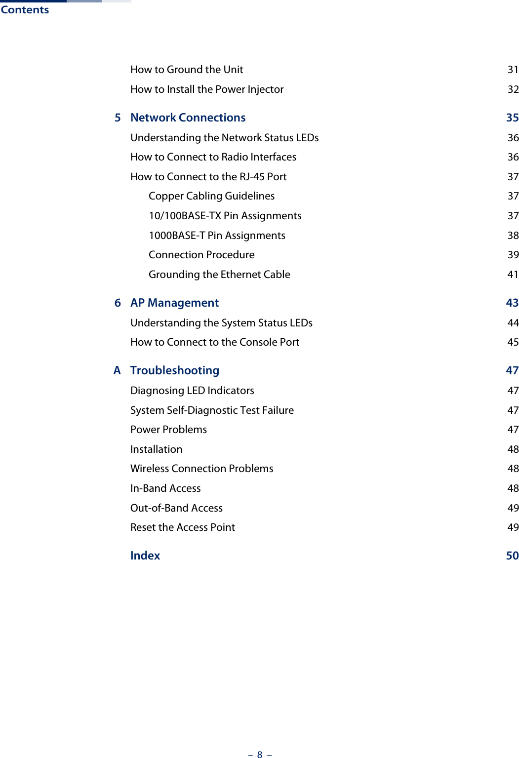
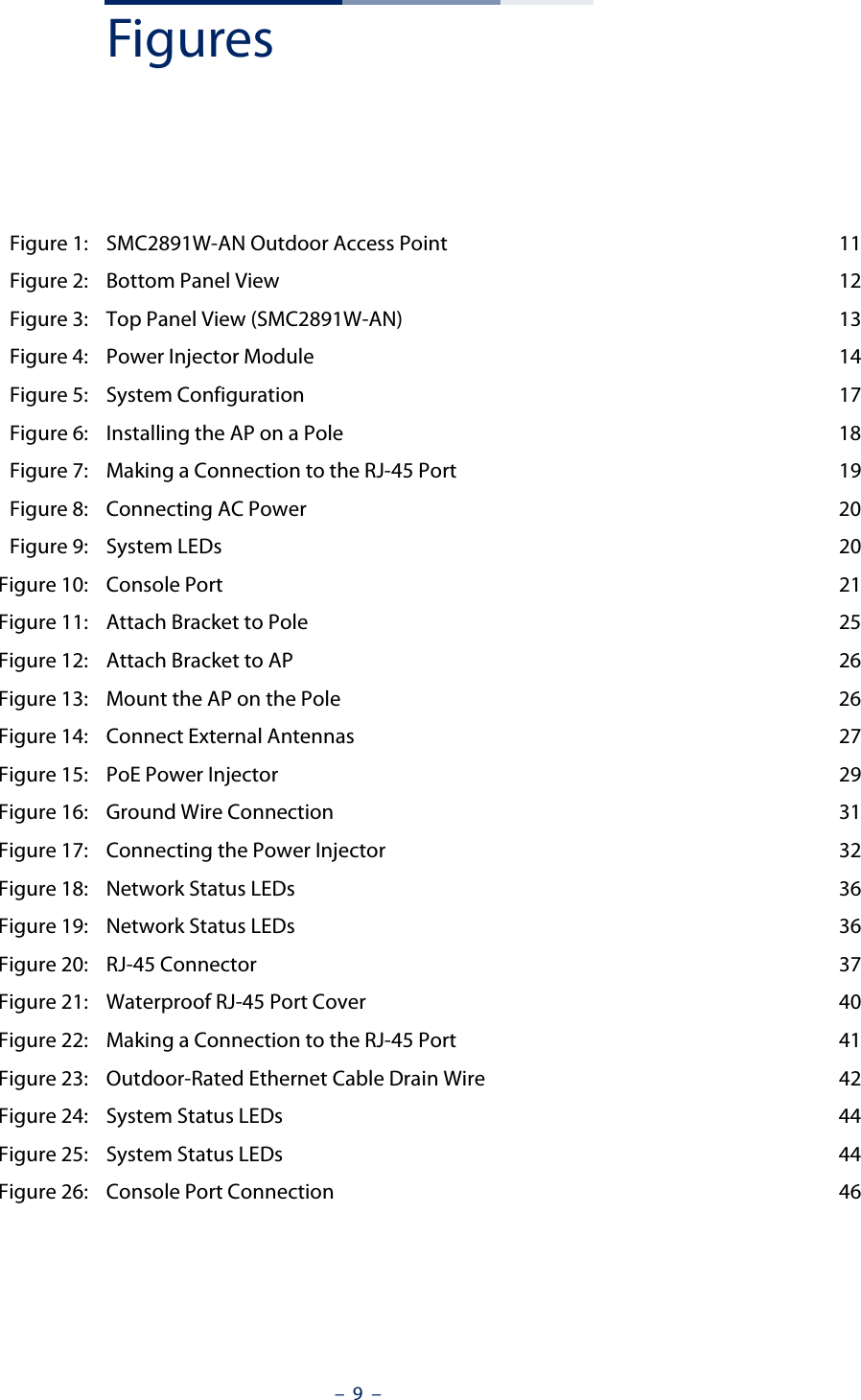
Contents
- 1. User Manual - IG
- 2. User Manual - MG
- 3. User Manual - QSG
- 4. User Manual - Statements
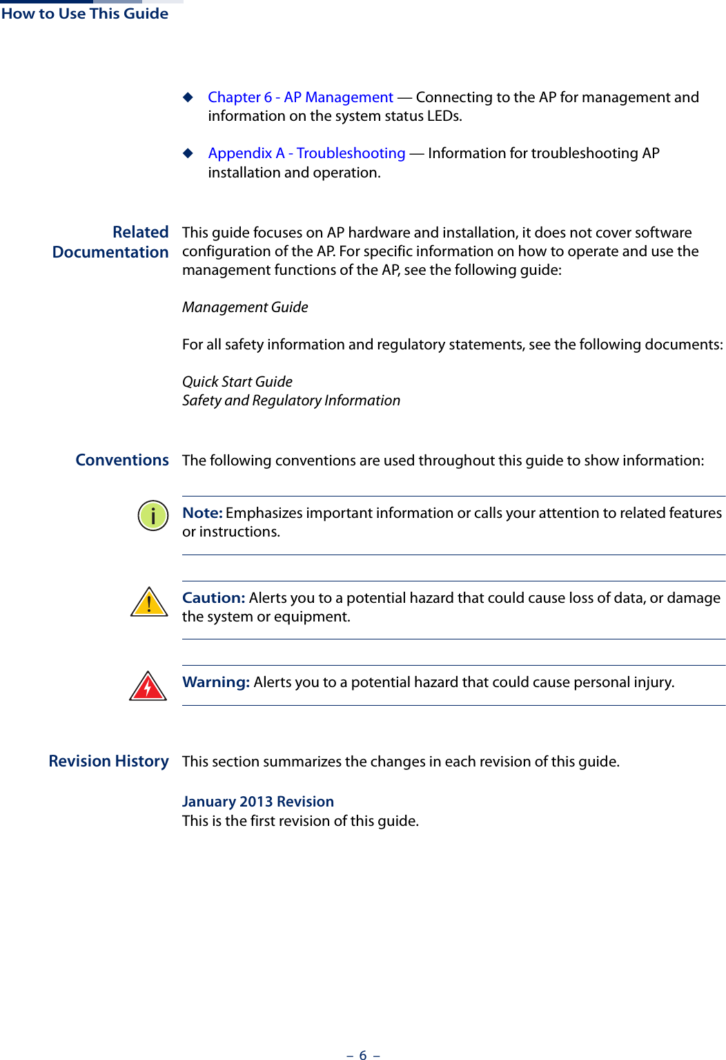
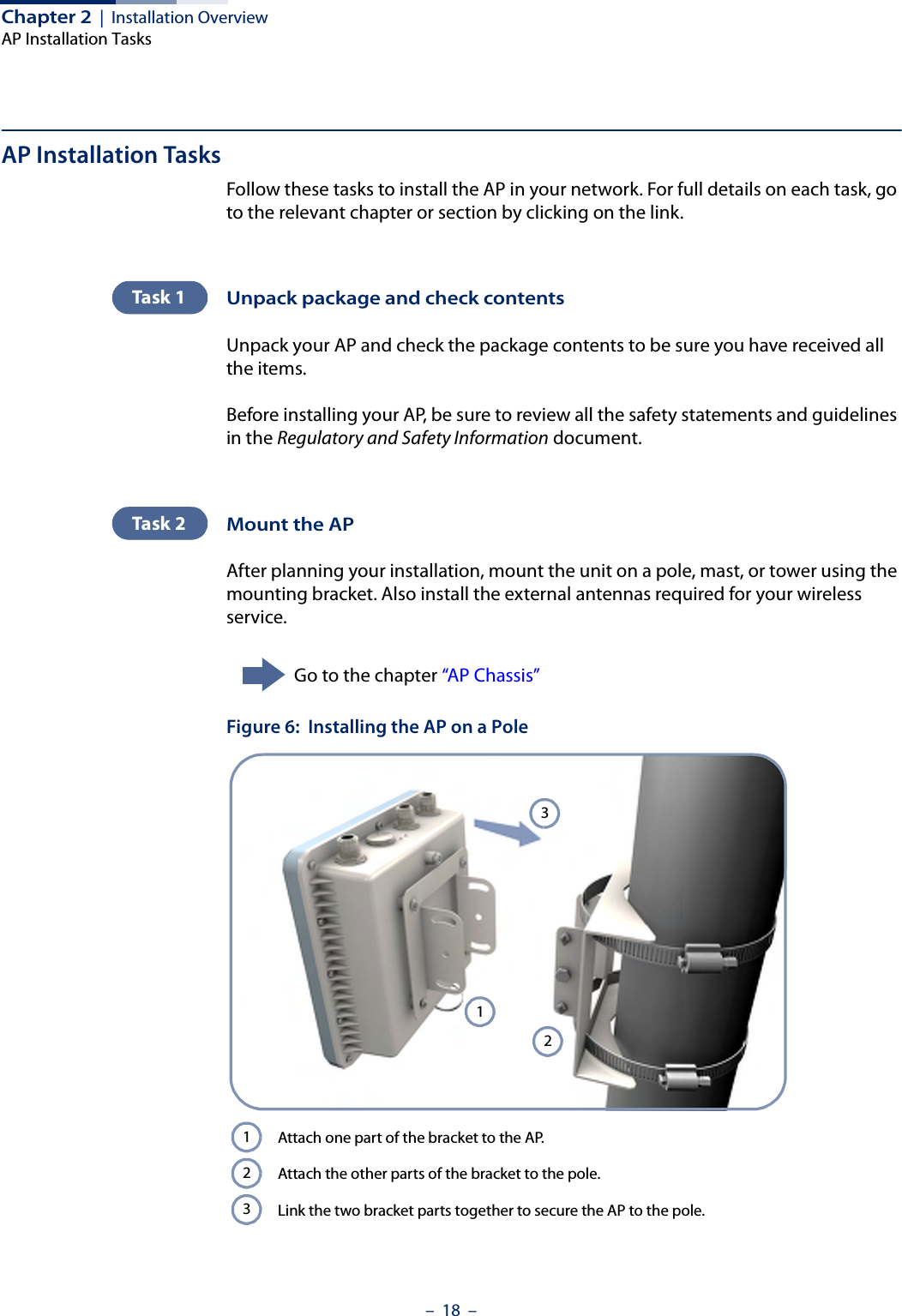
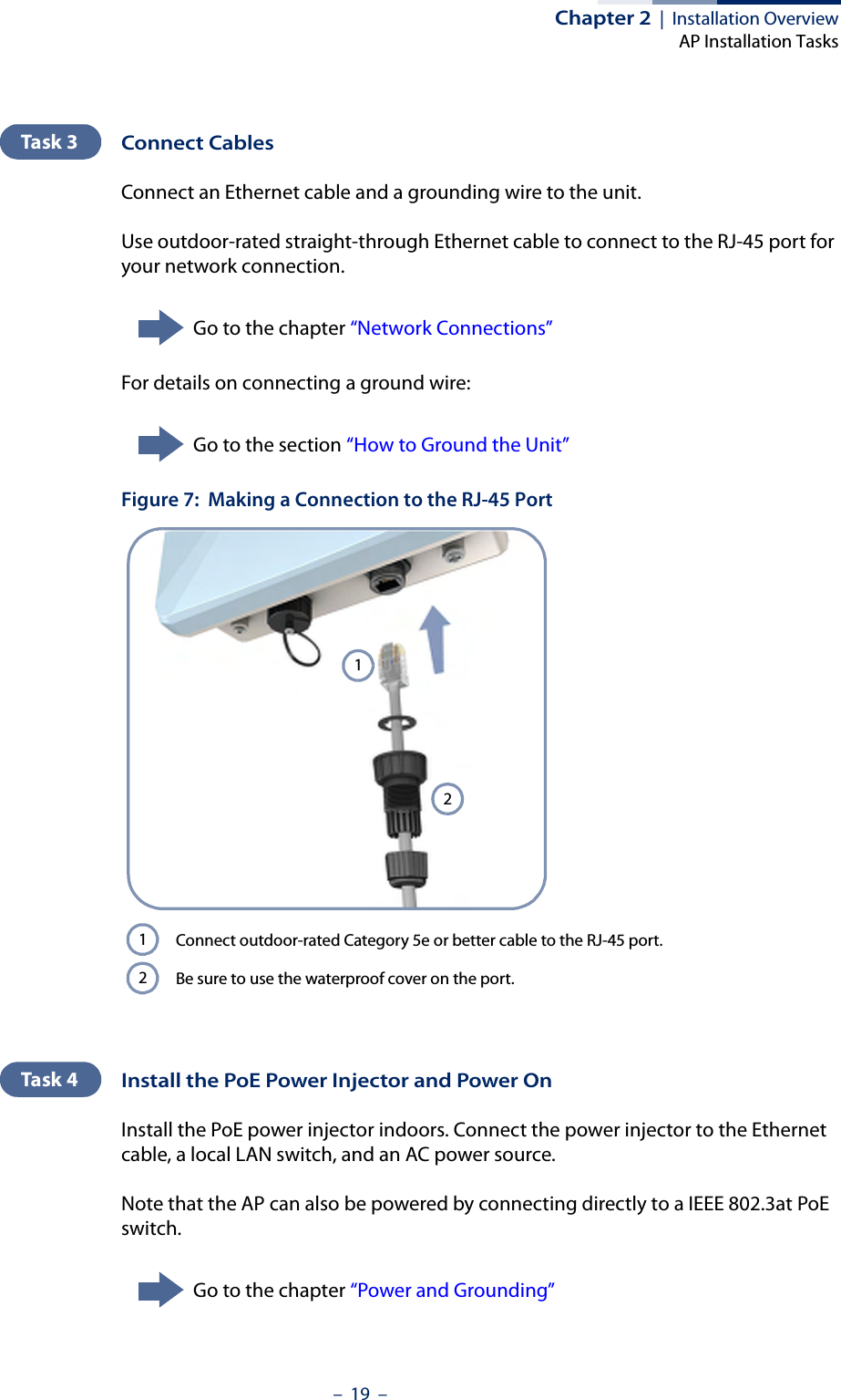
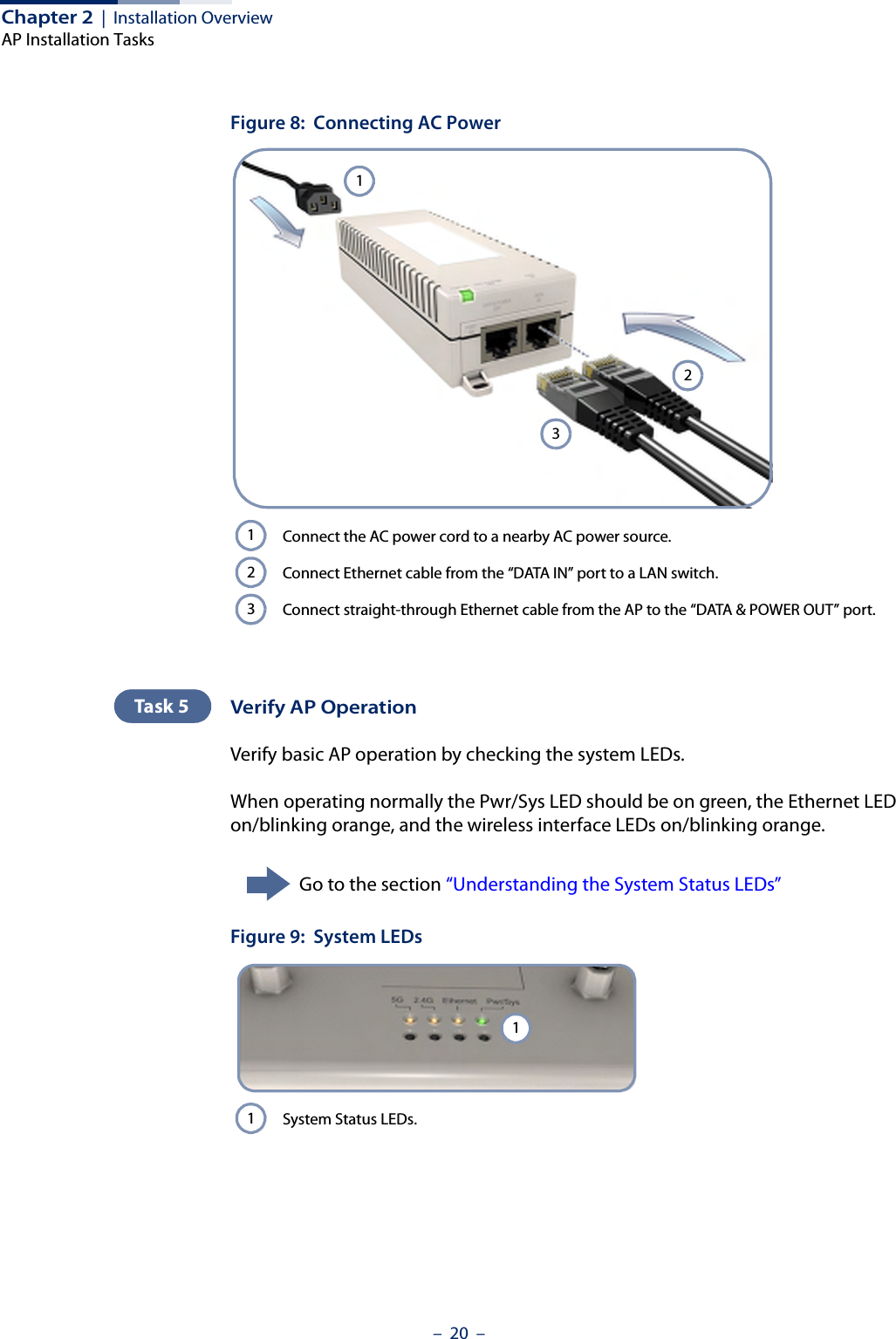
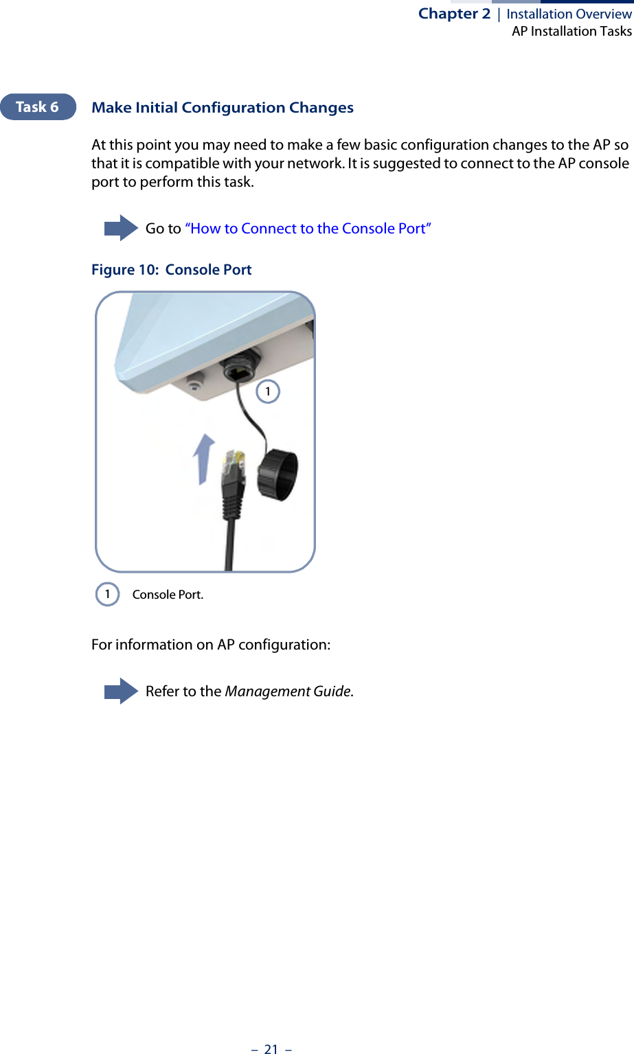
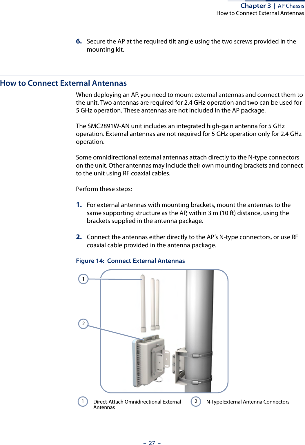
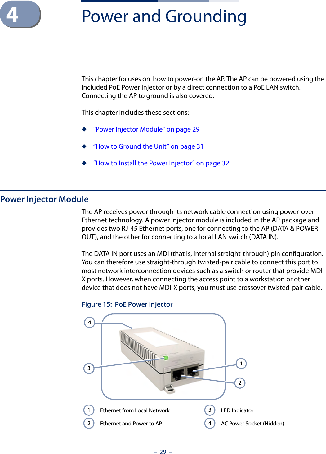
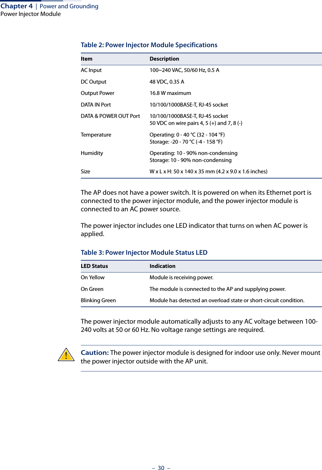
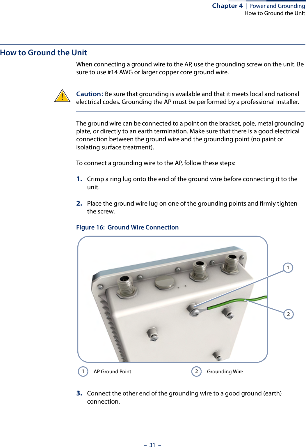
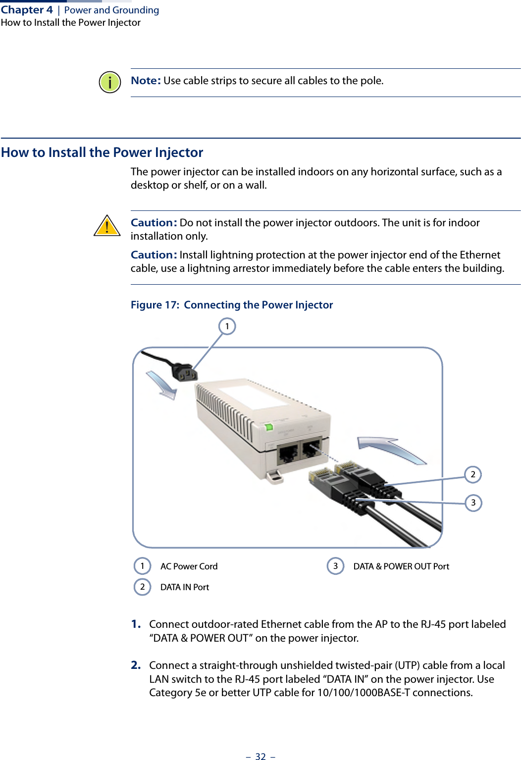
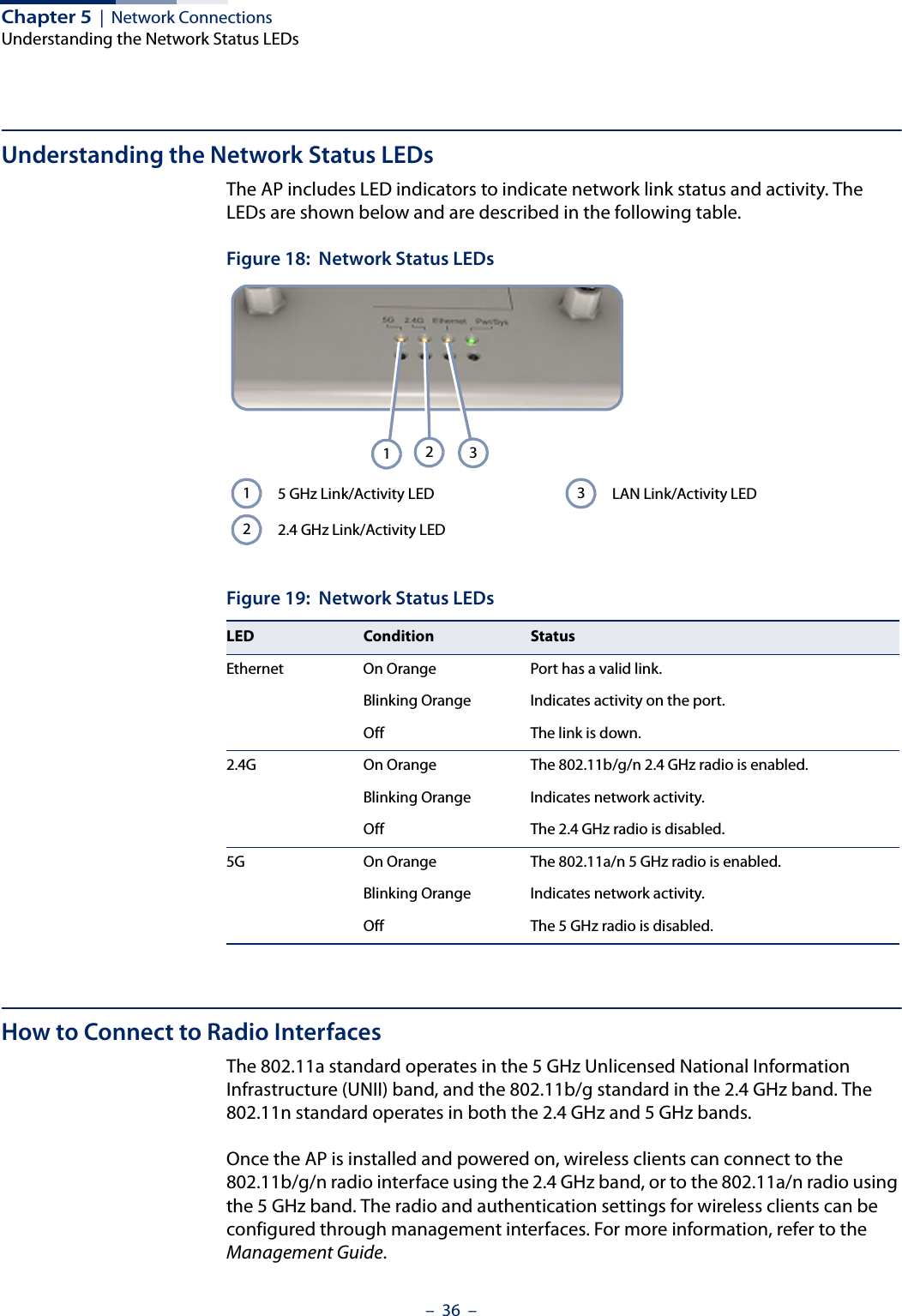
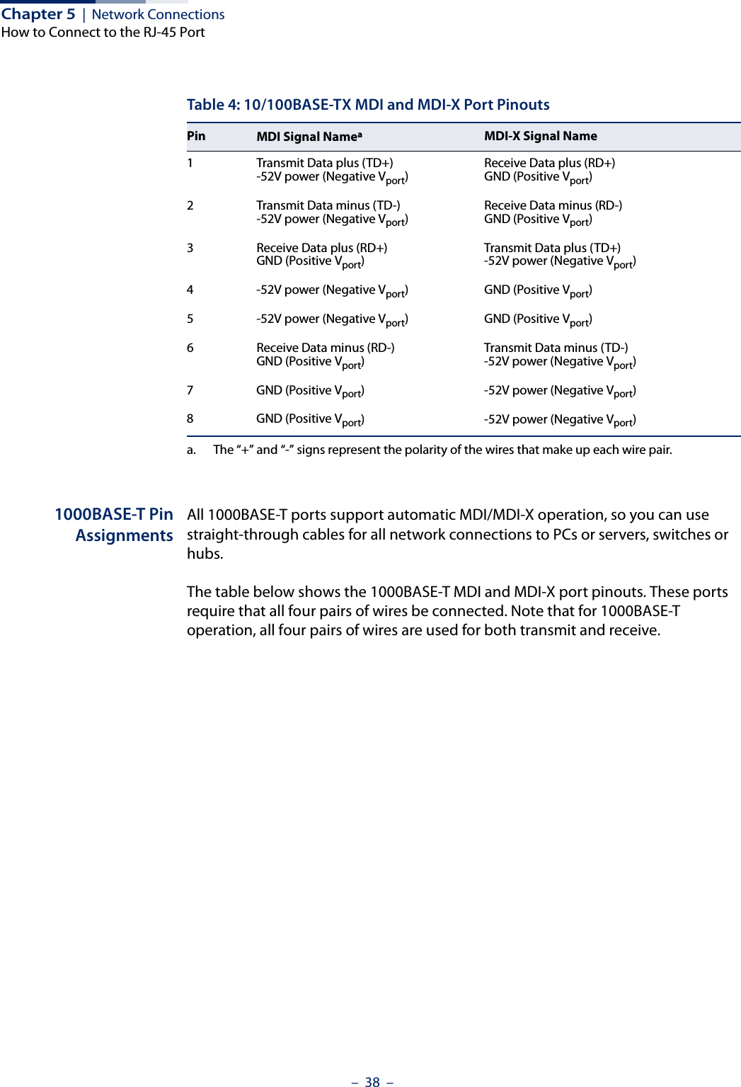
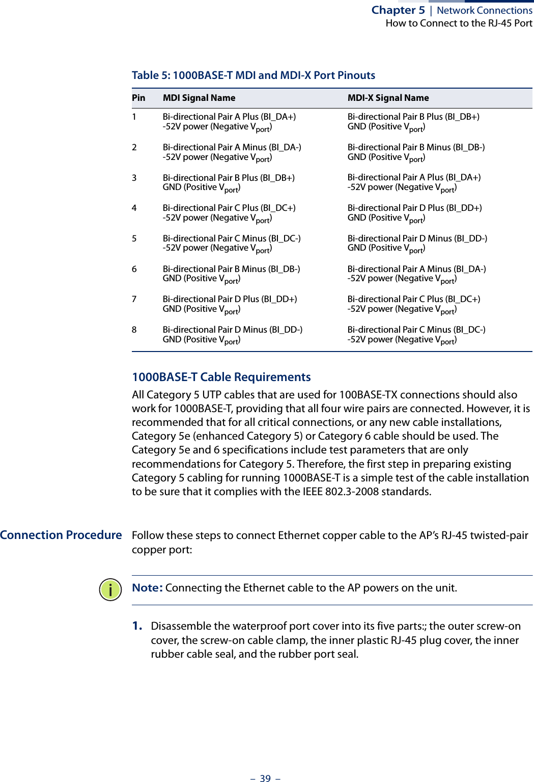
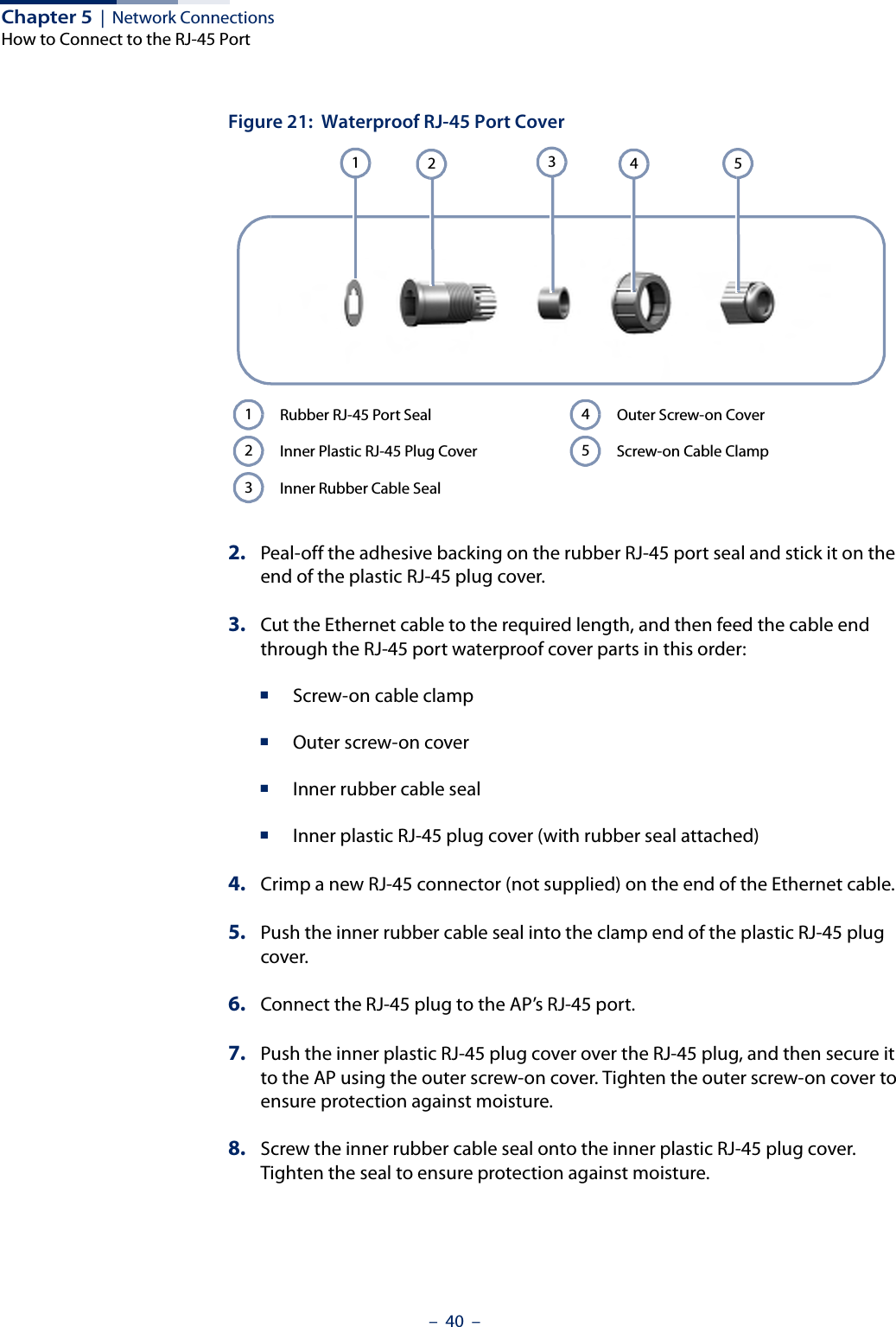
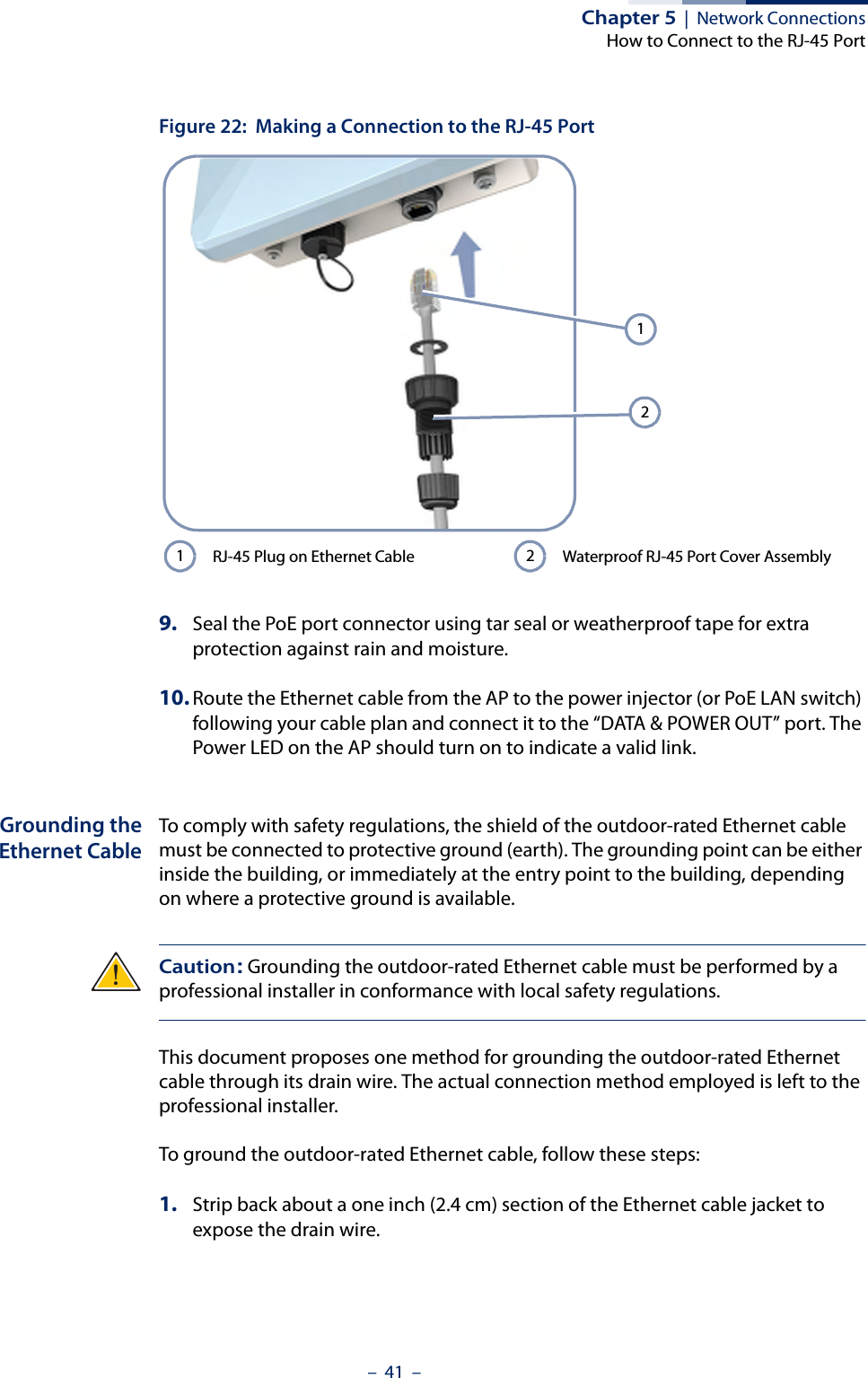
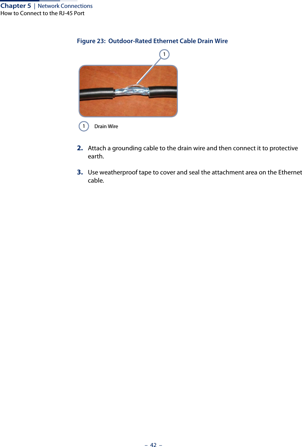
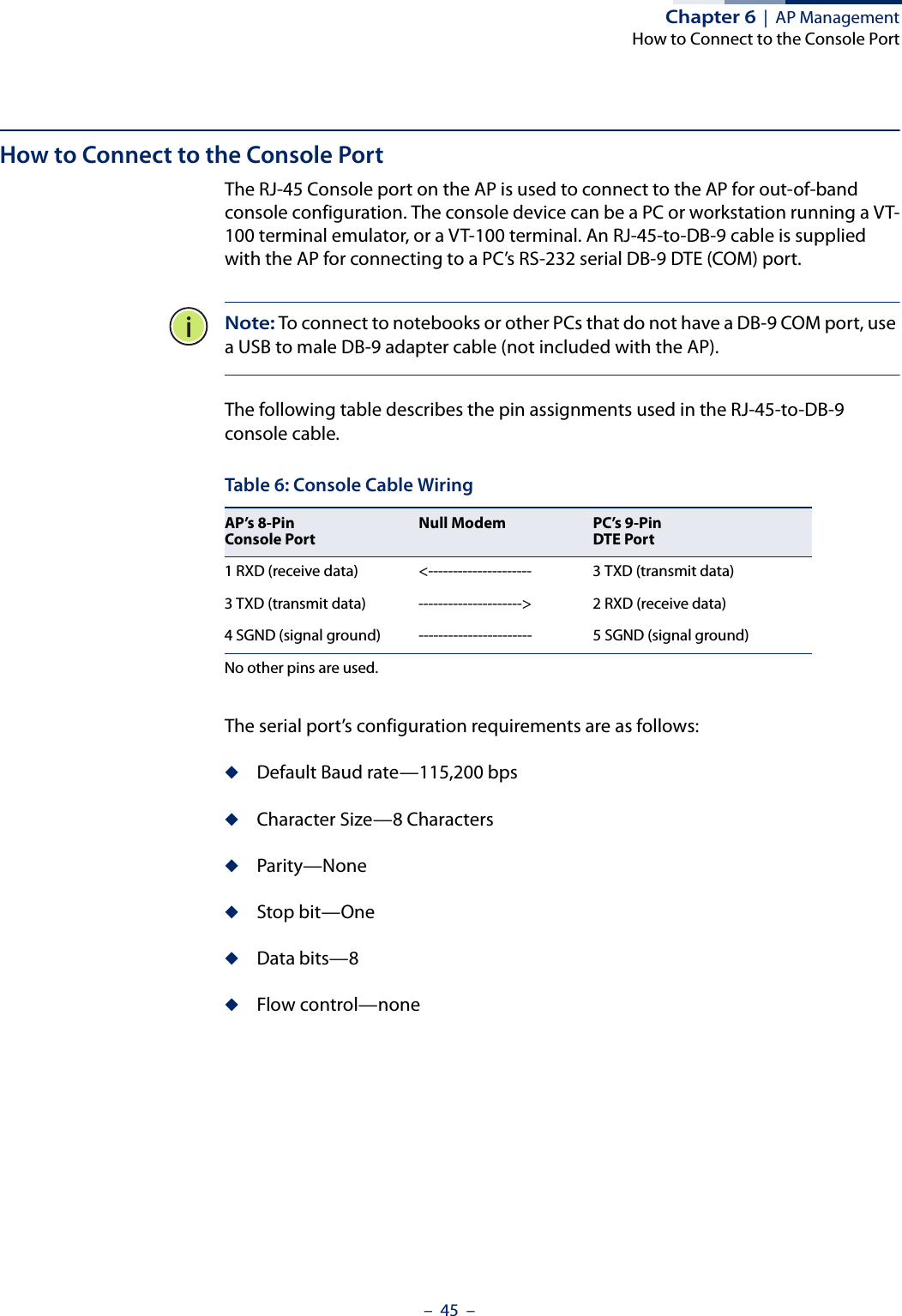
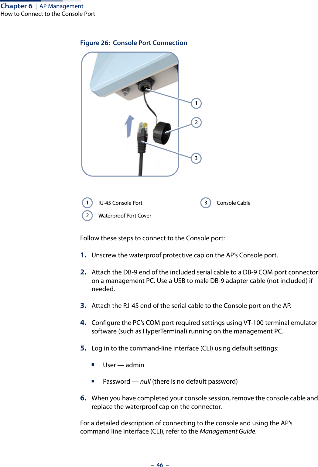
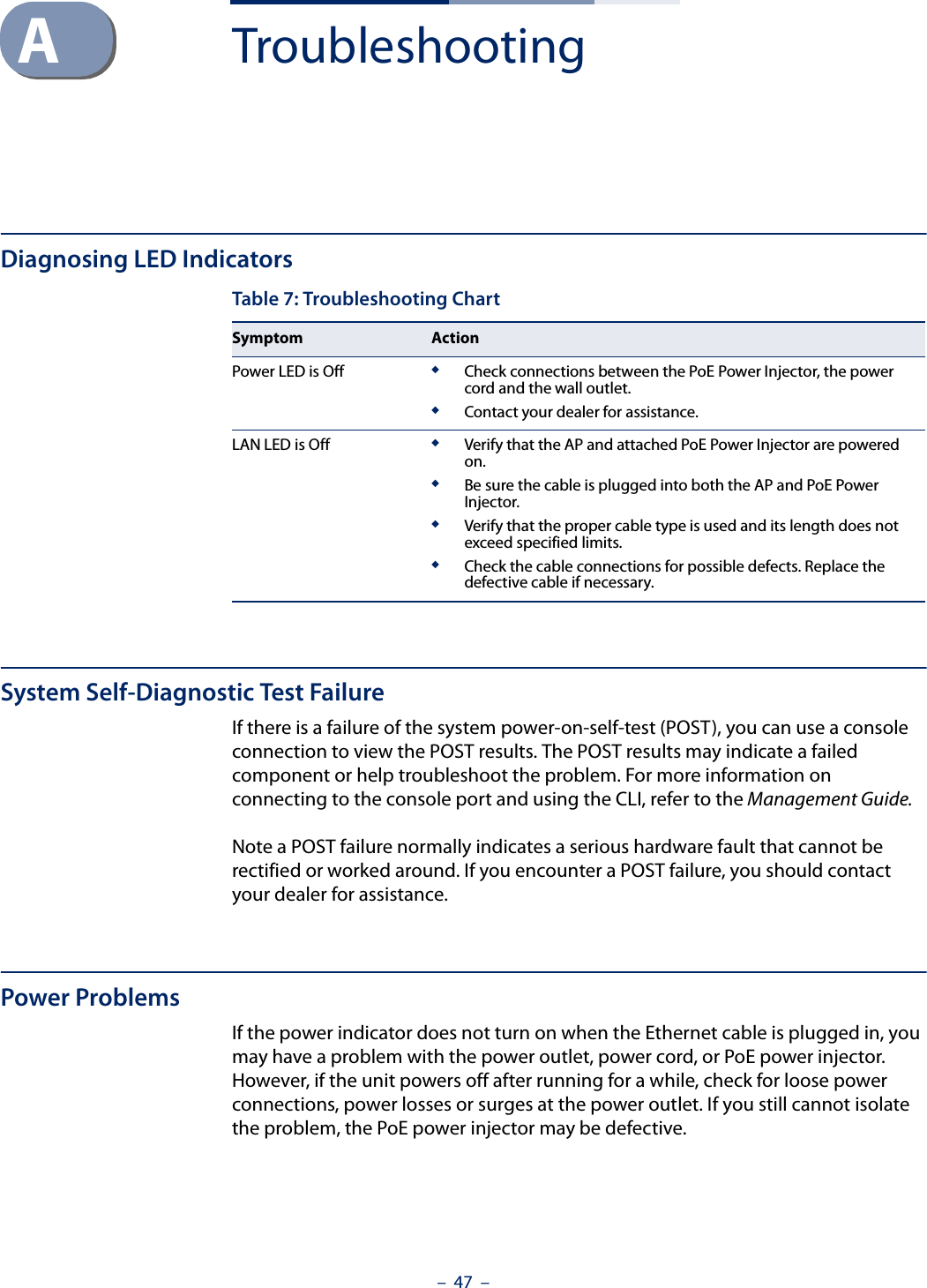
User Manual - IG