Edgecore Networks SMC7904WBRA-N2 Wireless N ADSL 2/2+ Modem Router User Manual number
Edgecore Networks Corporation Wireless N ADSL 2/2+ Modem Router number
UserManual.wiki
>
Edgecore Networks
>
SMC7904WBRA N2 User Manual
USers Manual
Navigation menu
Upload a User Manual
Namespaces
Wiki Guide
HTML
PDF
Info
Views
User Manual
Discussion / Help
Navigation
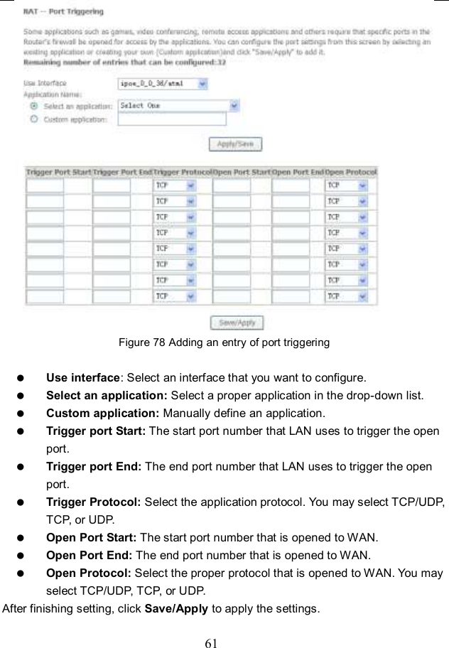
![63 Figure 80 Outgoing IP filtering setup By default, all outgoing IP traffic from LAN is allowed, but some IP traffic can be blocked by setting filters. In this page, you can add or remove the outgoing IP filtering rules. Click the Add button to display the following page. Figure 81 Adding an IP outgoing filtering rule In this page, you can create a filter rule to identify the outgoing IP traffic by specifying a new filter name and at least one condition. Filter Name: Set the filter name. IP Version: Select the proper IP version in the drop-down list. Protocol: Select a protocol that needs to be filtered. Source IP address [/prefix length]: Set the range of local IP address. Source Port (port or port: port): Set the local port. Destination IP address [/prefix length]: Set the range of IP address of the exterior network. Destination Port (port or port: port): Set the port of the exterior network. After finishing setting, click Apply/Save to save and activate the filtering rule.](https://usermanual.wiki/Edgecore-Networks/SMC7904WBRA-N2/User-Guide-1577288-Page-66.png)
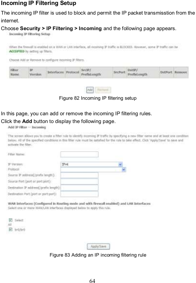
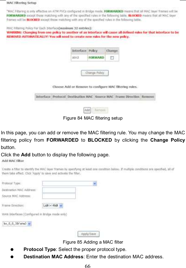
![65 In this page, you can create a filter rule to identify the incoming IP traffic by specifying a new filter name and at least one condition, and you must select at least one WAN interface for the rule. Filter Name: Set the filter name. IP Version: Select the proper IP version in the drop-down list. Protocol: Select a protocol that needs to be filtered. Source IP address [/prefix length]: Set the range of local IP address. Source Port (port or port: port): Set the local port. Destination IP address [/prefix length]: Set the range of IP address of the exterior network. Destination Port (port or port: port): Set the port of the exterior network. After finishing setting, click Apply/Save to save and activate the filtering rule. MAC Filtering Setup In some cases, you may want to manage Layer2 MAC address to block or permit a computer within the home network. When you enable MAC filter rules, the DSL router serves as a firewall that works at layer 2. Note: MAC filtering is only effective on ATM PVCs configured in bridge mode. If the ATM PVCs are configured in other routing modes (such as PPPoE mode), the MAC Filtering Setup page does not be configured. Choose Security > MAC Filtering and the following page appears.](https://usermanual.wiki/Edgecore-Networks/SMC7904WBRA-N2/User-Guide-1577288-Page-68.png)