Edgecore Networks SMCFS501 5 interface GM switch User Manual
Edgecore Networks Corporation 5 interface GM switch
user manual

1
10/100Mbps Fast Ethernet Switch
User Manual
RECYCLABLE

2
Chapter 1 INTRODUCTION
1.1 Product Briefs
The switch is a un-management 10/100Mbps switch, the Fast desktop
switches provides 5/8/16/24 10/100Mbps auto-negotiation ports, all
ports support Auto MDI / MDIX feature. Ideally designed for SOHO
and small workgroup networking connection, Simple and easy
installation, it eliminates networks bottleneck while giving users
flexibility and scalability.
1.2 Product Features
Table 1-1 Ethernet Switch Product Features
Item Description
Standard IEEE 802.3、IEEE 802.3u
Protocol CSMA/CD
Data Rate Ethernet:10Mbps@Half Duplex;20Mbps@Full Duplex
Fast Ethernet:100Mbps@ Half Duplex;200Mbps@ Full
Duplex
Topology Star
Ports 5/8/16/24 autosensing 10/100Mbps Ethernet ports

3
Network
Cables
10Base-T:
Category 3/4/5 shielded twisted pair (STP) with the
maximum transmission distance of 100 m
100Base-TX:
Category 5 STP with the maximum transmission distance
of 100 m
1.3 Physical & Environmental
Table 1-2 Ethernet Switch Environmental Features
Temperature Operating: 0° ~ 40° C (32℉ to 104℉)
Storage: -10° ~ 70° C (14℉ to 158℉)
Humidity Operating: 10% ~ 90% RH, non-condensing
Storage: 5% ~ 90% RH, non-condensing
System cooling Air cooling
1.4 Hardware Introduction
1.4.1 Product Appearance
1.Front Panel
The figure below shows the front panel of the Switch.

4
5/8-Port 10/100Mbps Switch Front Panel
16/24-Port 10/100Mbps Switch Front Panel
2.Rear Panel
The figure below shows the rear panel of the Switch. All MDI/MDI-X
ports and an external DC power adapter jack in the 5/8-port rear panel.
There is a AC inlet in the 16/24-Port switch rear panel.
5/8-Port Switch Rear Panel
16/24-Port Switch Rear Panel

5
Auto MDI/MDI-X Ports:
All ports support automatic MDI/MDI-X crossover detection. The Auto
MDI/MDI-X function makes it simple to connect to the switch—just
plug either a Crossover or Straight-Through CAT5 cable into any port.
DC Power Jack:
Power is supplied through an external DC power adapter. Check the
technical specification section for information about the DC power
input voltage.
AC inlet
Power is supplied through external AC power. The input AC voltage is
100~240V.
1.3.2 LED Indicators
Table 1-3 Ethernet Switch LED Indicators
LED Panel
signature Status Description
Green ON Switch is powered ON Power
Indicator Power OFF Switch is powered OFF
Green ON 100Mbit/s Speed
Indicator Speed OFF 10Mbit/s OR OFF
Green ON Link
Green
Blinking Activity
Status
Indicator Link/Act
OFF No link path
6
Chapter 2 CONNECTING THE SWITCH
z PC to Switch
A computer can be connected to the 8-Port 10/100Mbps Switch via a
two-pair Category 3, 4, 5 UTP/STP Straight-Through or Crossover
cable. A computer equipped with a RJ-45 10/100Mbps port can be
connected to any of the eight 8-Port 10/100Mbps Switch ports.
The LED indicators for the PC connection depend on the capability of
the computer’s Ethernet card. If the LED indicators are not lit after
making a proper connection, check the computer’s Ethernet card, the
cable, and the 8-Port 10/100Mbps Switch’s conditions and connections.
z Hub to Switch
A hub (10 or 100BASE-TX) can be connected to the 8-Port
10/100Mbps Switch via a two-pair Category 3, 4, or 5 UTP/STP
Straight-Through or Crossover cable. For 100Mbps operation a
Category 5 cable must be used. The connection is accomplished from
any port of the hub to any port of the 8-Port 10/100Mbps Switch.
7
z Switch to other devices
The 8-Port 10/100Mbps Switch can be connected to another switch or
other devices (routers, bridges, etc.) via a two-pair Category 3, 4, 5
UTP/STP Straight-Through or Crossover cable. A Category 5 cable
must be used for 100Mbps operation. The connection can be
accomplished from any (MDI-X) port on the 8-Port 10/100Mbps
Switch to any of the 10Mbps or 100Mbps (MDI-X) ports on another
switch or other devices.
z Port Speed & Duplex Mode
After plugging the selected cable to a specific port, the system uses
auto-negotiation to determine the transmission mode, auto-detecting the
network speed (10Mbps or 100Mbps) for any new twisted-pair
connection.
If the attached device does not support auto-negotiation or has
auto-negotiation disabled, an auto-sensing process is initiated to select
the speed and half-duplex mode is selected.
8
Chapter 3 MOUNTING THE SWITCH ON A WALL
The 8-Port 10/100Mbps Switch can also be mounted on a wall. Two
mounting slots are provided on the bottom of the switch for this
purpose. Please make sure that the front panel is exposed in order to
view the LEDs. Please refer to the illustration below:
A.) Mounting on a cement wall
1. Mount the Nylon screw anchors into a cement wall.
2. Drive the T3 x 15L screws into the Nylon screw anchors.
3. Hook the mounting holes of the switch back on the screws; you have
completed the wall-mount.
B.) Mounting on a wood wall
1. Drive the T3 x 15 L screws into the wood wall.
2. Hook the mounting holes of the switch back on the screws; you have
completed the wall-mount.
(1) 3/4 inch minimum for wood wall
(2) 3 inch minimum for cement wall
9
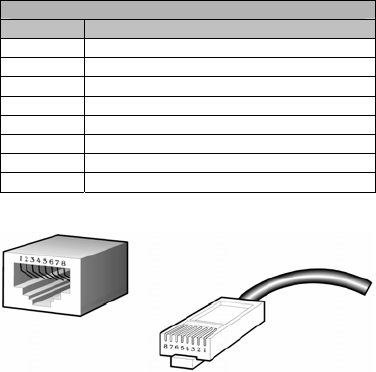
Annex RJ-45 PIN SPECIFICATION
The following diagram and tables show the standard RJ-45
receptacle/connector and their pin assignments.
RJ-45 Connector pin assignment
Contact Media Direct Interface Signal
1 Rx +(receive)
2 Rx - (receive)
3 Tx + (transmit)
4 Not used
5 Not used
6 Tx - (transmit)
7 Not used
8 Not used
RJ-45 Connector pin assignment
Standard RJ-45 receptacle/connector
FCC
6WDWHPHQW
Federal Communication Commission Interference Statement
This equipment has been tested and found to comply with the limits for a Class B digital device,
pursuant to
Part
15
of the FCC Rules. These limits are designed to provide reasonable protection
against harmful interference in a residential
installation.
This equipment generates, uses and can
radiate radio
frequency
energy
and, if not installed and used in accordance with the instructions,
may cause harmful interference to radio communications. However, there is no guarantee that
interference will not occur in a particular installation.
If this equipment does cause harmful
interference to radio or television reception, which can be determined by turning the equipment off
and on, the user is encouraged to try to correct the interference by one of the following measures:
-Reorient or relocate the receiving antenna.
-Increase the separation between the equipment and receiver.
-Connect the equipment into an outlet on a circuit different from that to which the receiver is
connected.
-Consult the dealer or an experienced radio/TV technician for help.
This device complies with Part 15 of the FCC Rules. Operation is subject to the following two
conditions: (1) This device may not cause harmful interference, and (2) this device must accept any
interference received, including interference that may cause undesired operation.
FCC Caution: Any changes or modifications not expressly approved by the party responsible for
compliance could void the user's authority to operate this equipment.