Edgecore Networks SMCFS801 8 interface GM switch User Manual
Edgecore Networks Corporation 8 interface GM switch
UserManual.wiki
>
Edgecore Networks
>
SMCFS801 User Manual
user manual
Navigation menu
Upload a User Manual
Namespaces
Wiki Guide
HTML
PDF
Info
Views
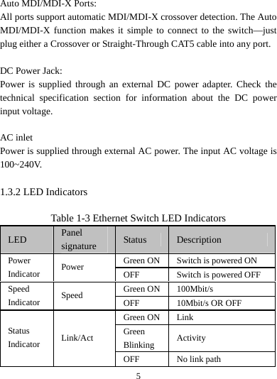
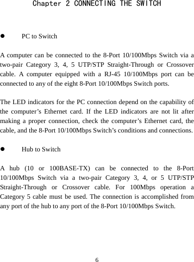
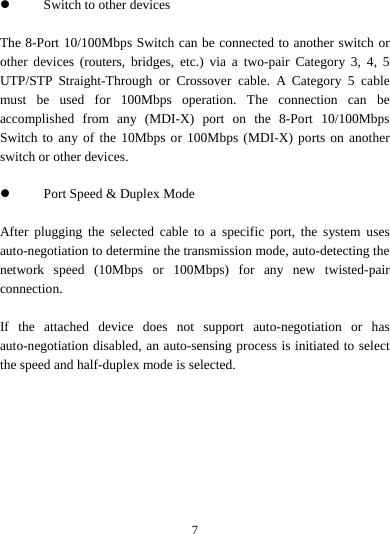
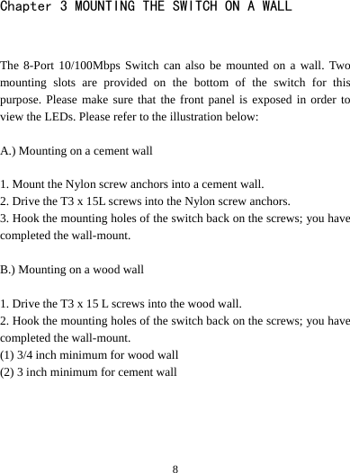
User Manual
Discussion / Help
Navigation