Edgecore Networks SMCWBR14SN5 300 Mbps 4-port Wireless Broadband Router User Manual User Guide
Edgecore Networks Corporation 300 Mbps 4-port Wireless Broadband Router User Guide
User Manual

USER GUIDE
BARRICADE™ N
150/300Mbps 4-Port Wireless Broadband Router
SMCWBR14S-N5, SMCWBR14-N5

No. 1, Creation Road III,
Hsinchu Science Park,
30077, Taiwan, R.O.C.
TEL: +886 3 5770270
Fax: +886 3 5780764
Wireless Broadband Router
User Guide
June 2011
Pub. # 149100000009W
SMC-UG-0611-01
Information furnished by SMC Networks, Inc. (SMC) is believed to be accurate and reliable.
However, no responsibility is assumed by SMC for its use, nor for any infringements of patents or
other rights of third parties which may result from its use. No license is granted by implication or
otherwise under any patent or patent rights of SMC. SMC reserves the right to change specifications
at any time without notice.
Copyright © 2011 by
SMC Networks, Inc.
No. 1 Creation Road III,
Hsinchu Science Park,
30077, Taiwan, R.O.C.
All rights reserved
Trademarks:
SMC is a registered trademark; and Barricade, EZ Switch, TigerStack, TigerSwitch, and TigerAccess
are trademarks of SMC Networks, Inc. Other product and company names are trademarks or
registered trademarks of their respective holders.
– 4 –
WARRANTY AND PRODUCT REGISTRATION
To register SMC products and to review the detailed warranty statement,
please refer to the Support Section of the SMC Website at http://
www.smc.com.

– 5 –
COMPLIANCES
FEDERAL COMMUNICATION COMMISSION INTERFERENCE STATEMENT
This equipment has been tested and found to comply with the limits for a
Class B digital device, pursuant to part 15 of the FCC Rules. These limits
are designed to provide reasonable protection against harmful interference
in a residential installation. This equipment generates, uses and can
radiate radio frequency energy and, if not installed and used in accordance
with the instructions, may cause harmful interference to radio
communications. However, there is no guarantee that interference will not
occur in a particular installation. If this equipment does cause harmful
interference to radio or television reception, which can be determined by
turning the equipment off and on, the user is encouraged to try to correct
the interference by one or more of the following measures:
◆Reorient or relocate the receiving antenna
◆Increase the separation between the equipment and receiver
◆Connect the equipment into an outlet on a circuit different from that to
which the receiver is connected
◆Consult the dealer or an experienced radio/TV technician for help
This device complies with Part 15 of the FCC Rules. Operation is subject to
the following two conditions: (1) This device may not cause harmful
interference, and (2) this device must accept any interference received,
including interference that may cause undesired operation.
FCC Caution: Any changes or modifications not expressly approved by the
party responsible for compliance could void the user's authority to operate
this equipment.
N
OTE
:
The manufacturer is not responsible for any radio or TV interference
caused by unauthorized modifications to this equipment. Such
modifications could void the user’s authority to operate the equipment.

C
OMPLIANCES
– 6 –
IMPORTANT NOTE:
FCC RADIATION EXPOSURE STATEMENT
This equipment complies with FCC RF radiation exposure limits set forth for
an uncontrolled environment. This device and its antenna must not be co-
located or operating in conjunction with any other antenna or transmitter.
“To comply with FCC RF exposure compliance requirements, this grant is
applicable to only Mobile Configurations. The antennas used for this
transmitter must be installed to provide a separation distance of at least 20
cm from all persons and must not be co-located or operating in conjunction
with any other antenna or transmitter.”
CE MARK WARNING
SMC contact for these products in Europe is:
SMC Networks Europe,
C/Fructuós Gelabert 6-8, 2o, 2a,
Edificio Conata II,
08970 - Sant Joan Despí, Barcelona, Spain.
This is a class B product. In a domestic environment, this product may
cause radio interference, in which case the user may be required to take
adequate measures.
NATIONAL RESTRICTIONS
This device is intended for home and office use in all EU countries (and
other countries following the EU directive 1999/5/EC) without any
limitation except for the countries mentioned below:
N
OTE
:
Do not use the product outdoors in France.
Country Restriction Reason/Remark
Bulgaria None General authorization required for outdoor use and
public service
France Outdoor use
limited to 10 mW
e.i.r.p. within the
band 2454-2483.5
MHz
Military Radiolocation use. Refarming of the 2.4 GHz
band has been ongoing in recent years to allow
current relaxed regulation. Full implementation
planned 2012
italy None If used outside of own premises, general
authorization is required
Luxembourg None General authorization required for network and
service supply(not for spectrum)
Norway Implemented This subsection does not apply for the geographical
area within a radius of 20 km from the centre of Ny-
Ålesund
Russian
Federation None Only for indoor applications
– 7 –
ABOUT THIS GUIDE
PURPOSE This guide details the hardware features of the wireless router, including its
physical and performance-related characteristics, and how to install the
device and use its configuration software.
AUDIENCE This guide is for PC users with a working knowledge of computers. You
should be familiar with Windows operating system concepts.
CONVENTIONS The following conventions are used throughout this guide to show
information:
N
OTE
:
Emphasizes important information or calls your attention to related
features or instructions.
C
AUTION
:
Alerts you to a potential hazard that could cause loss of data, or
damage the system or equipment.
W
ARNING
:
Alerts you to a potential hazard that could cause personal injury.
RELATED PUBLICATIONS The following publication gives basic information on how to install and use
the wireless router.
Quick Installation Guide
Also, as part of the wireless router’s software, there is online help that
describes all configuration related features.
REVISION HISTORY This section summarizes the changes in each revision of this guide.
JUNE 2011 REVISION
This is the first revision of this guide.

– 8 –
A
BOUT
T
HIS
G
UIDE

– 9 –
CONTENTS
WARRANTY AND PRODUCT REGISTRATION 4
COMPLIANCES 5
ABOUT THIS GUIDE 7
CONTENTS 9
FIGURES 12
TABLES 16
1I
NTRODUCTION 17
Overview of the Routers 17
Conventions 18
Main Features 18
Key Hardware Features 19
Package Contents 19
Front Panel 20
LED Indicators 20
Rear Panel 21
Wireless Antennas 21
Power 21
Reset Button 21
Ethernet WAN Port 21
Ethernet LAN Ports 21
2CONNECTING THE ROUTER 22
System Requirements 22
Installation Environment Requirements 22
Connecting the Router 22
3QUICK INSTALLATION GUIDE 24
TCP/IP Configuration 24
Quick Installation Guide 26

C
ONTENTS
– 10 –
4CONFIGURING THE ROUTER 32
Login 32
Status 33
Quick Setup 34
WPS 34
Adding a New Device: 34
Network 42
WAN 42
MAC Clone 51
LAN 52
Dynamic DNS 53
Binding Setting 55
Wireless 56
Wireless Settings 57
Wireless Security 59
Wireless MAC Filtering 63
Wireless Advanced 65
Wireless Statistics 67
WPS 67
DHCP 76
DHCP Settings 76
DHCP Clients List 77
Address Reservation 78
Special Application 79
Virtual Servers 79
Port Triggering 81
DMZ 84
UPnP 84
Security 86
Basic Security 86
Advanced Security 88
Access Control 89
Rule 89
Host 92
Target 94
Schedule 97

C
ONTENTS
– 11 –
Parental Control 99
Advanced Routing 102
QoS Settings 103
QoS Settings 103
Rules List 103
System Tools 105
Time Settings 105
Diagnostic 107
Settings Management 108
Password 111
System Log 112
Statistics 114
Local Management 116
Remote Management 117
ACONFIGURING THE PC 118
Install TCP/IP Components 118
B FAQ 122
How do I configure the Router for Internet access by ADSL users? 122
How do I configure the Router for Internet access by Ethernet users? 123
I want to use Netmeeting, what do I need to do? 124
I want to build a WEB Server on the LAN, what should I do? 126
Wireless stations cannot connect to the Router 128
CSPECIFICATIONS 129
GLOSSARY 131
INDEX 133

– 12 –
FIGURES
Figure 1: Front Panel 20
Figure 2: Rear Panel 21
Figure 3: Hardware Installation 23
Figure 4: Success Result of a Ping Command 25
Figure 5: Failure of a Ping Command 25
Figure 6: Log in to the Router 26
Figure 7: Windows Login 26
Figure 8: Quick Setup 27
Figure 9: Choose the WAN Connection Type 27
Figure 10: Quick Setup – PPPoE 28
Figure 11: Quick Setup - Static IP 28
Figure 12: Quick Setup – Wireless 29
Figure 13: Quick Setup – Finish 30
Figure 14: Quick Setup - Finish 31
Figure 15: The Main Menu 32
Figure 16: Status 33
Figure 17: WPS (Wi-Fi Protected Setup) 34
Figure 18: Front Panel 35
Figure 19: WPS Button 35
Figure 20: The WPS Configuration Screen of Wireless Adapter 36
Figure 21: The WPS Configuration Screen of Wireless Adapter 36
Figure 22: The WPS Configuration Screen of Wireless Adapter 37
Figure 23: Add A New Device 37
Figure 24: The WPS Configuration Screen of Wireless Adapter 38
Figure 25: The WPS Configuration Screen of Wireless Adapter 38
Figure 26: Add Device 39
Figure 27: The WPS Configuration Screen of Wireless Adapter 40
Figure 28: The WPS Configuration Screen of Wireless Adapter 41
Figure 29: Add a New Device 41
Figure 30: The Network Menu 42
Figure 31: WAN-Dynamic IP 42

C
ONTENTS
– 13 –
Figure 32: WAN-Static IP 43
Figure 33: WAN-PPPoE 44
Figure 34: WAN-PPPoE Advanced Settings 46
Figure 35: WAN-BigPond Cable 47
Figure 36: WAN-L2TP 48
Figure 37: WAN-PPTP 50
Figure 38: MAC Address Clone 51
Figure 39: LAN 52
Figure 40: Dyndns.org DDNS Settings 53
Figure 41: No-ip.com DDNS Settings 54
Figure 42: Binding Setting 55
Figure 43: IP & MAC Binding Setting (Add & Modify) 55
Figure 44: Find IP & MAC Binding Entry 56
Figure 45: Wireless Menu 56
Figure 46: Wireless Settings 57
Figure 47: Note Dialog 58
Figure 48: Enable WDS 59
Figure 49: Wireless Security 60
Figure 50: WEP 60
Figure 51: WPA/WPA2 62
Figure 52: WPA-PSK 62
Figure 53: Wireless MAC Address Filtering 63
Figure 54: Add or Modify Wireless MAC Address Filtering Entry 64
Figure 55: Filtering Rules 65
Figure 56: Wireless Advanced 65
Figure 57: Wireless Statistics 67
Figure 58: WPS (Wi-Fi Protected Setup) 68
Figure 59: Front Panel 69
Figure 60: WPS Button 69
Figure 61: The WPS Configuration Screen of Wireless Adapter 69
Figure 62: Front Panel 70
Figure 63: The WPS Configuration Screen of Wireless Adapter 70
Figure 64: The WPS Configuration Screen of Wireless Adapter 71
Figure 65: Add A New Device 71
Figure 66: The WPS Configuration Screen of Wireless Adapter 72
Figure 67: The WPS Configuration Screen of Wireless Adapter 72

C
ONTENTS
– 14 –
Figure 68: Add Device 73
Figure 69: The WPS Configuration Screen of Wireless Adapter 74
Figure 70: The WPS Configuration Screen of Wireless Adapter 75
Figure 71: Add a New Device 75
Figure 72: The DHCP Menu 76
Figure 73: DHCP Settings 76
Figure 74: DHCP Clients List 77
Figure 75: Address Reservation 78
Figure 76: Add or Modify an Address Reservation Entry 79
Figure 77: The Special Application Menu 79
Figure 78: Virtual Servers 80
Figure 79: Add or Modify a Virtual Server Entry 81
Figure 80: Port Triggering 82
Figure 81: Add or Modify a Triggering Entry 83
Figure 82: DMZ 84
Figure 83: UPnP 85
Figure 84: The Security menu 86
Figure 85: Basic Security 86
Figure 86: Advanced Security 88
Figure 87: Access Control 89
Figure 88: Access Control Rule Management 90
Figure 89: Add or Modity Internet Access Control Entry 91
Figure 90: Host Settings 92
Figure 91: Add or Modify an IP Host Entry 93
Figure 92: Add or Modify a MAC Host Entry 94
Figure 93: Target Settings 94
Figure 94: Add or Modify an IP Access Target Entry 95
Figure 95: Add or Modify a Domain Name Access Target Entry 96
Figure 96: Target Setting 96
Figure 97: Schedule Settings 97
Figure 98: Advanced Schedule Settings 98
Figure 99: Parental Control Settings 99
Figure 100: Add or Modify Parental Control Entry 100
Figure 101: Parental Control Settings 101
Figure 102: Static Routing 102
Figure 103: Add or Modify a Static Route Entry 102

C
ONTENTS
– 15 –
Figure 104: QoS Settings 103
Figure 105: QoS Rule List 104
Figure 106: Qos Rule Settings 104
Figure 107: The System Tools Menu 105
Figure 108: Time Settings 105
Figure 109: Diagnostic Tools 107
Figure 110: Diagnostic Results 108
Figure 111: Firmware Upgrade 108
Figure 112: Restore Factory Default 109
Figure 113: Backup & Restore Configuration 110
Figure 114: Reboot 111
Figure 115: Password 111
Figure 116: System Log 112
Figure 117: Mail Account Settings 113
Figure 118: Statistics 114
Figure 119: Local Management 116
Figure 120: Remote Management 117
Figure 121: TCP/IP 118
Figure 122: Internet Protocol 119
Figure 123: Internet Protocol Properties 120
Figure 124: Setting the IP Address Manually 121
Figure 125: PPPoE Connection Type 122
Figure 126: PPPoE Connection Mode 122
Figure 127: MAC Clone 123
Figure 128: Virtual Servers 124
Figure 129: Add or Modify a Virtual Server Entry 124
Figure 130: DMZ 125
Figure 131: Basic Security 126
Figure 132: Remote Management 126
Figure 133: Virtual Servers 127
Figure 134: Add or Modify a Virtual Server Entry 127


– 17 –
1INTRODUCTION
OVERVIEW OF THE ROUTERS
The Barricade™ SMCWBR14S-N5 150Mbps 4-Port Wireless Broadband
Router and SMCWBR14-N5 300Mbps 4-Port Wireless Broadband Router
deliver exceptional range and speed, which can fully meet the needs of
Small Office/Home Office (SOHO) networks and users demanding higher
network performance. The routers integrate a 4-port switch, firewall, NAT
router, and wireless access point (AP).
INCREDIBLE SPEED
The SMCWBR14S-N5 provides up to 150 Mbps wireless connections with
other 802.11n wireless clients, and the SMCWBR14-N5 provides up to
300 Mbps connections. The speed makes the routers ideal for handling
multiple data streams at the same time, which ensures your network
remains stable and smooth. The routers are compatible with all IEEE
802.11g and IEEE 802.11b products.
MULTIPLE SECURITY PROTECTIONS
With multiple protection measures, including SSID broadcast control, 64/
128/152-bit WEP encryption, Wi-Fi protected Access (WPA2-PSK, WPA-
PSK), as well as advanced firewall protection, the routers provide complete
data privacy.
FLEXIBLE ACCESS CONTROL
The routers provide flexible access control, so that parents or network
administrators can establish restricted access policies for children or staff.
It also supports Virtual Server and DMZ host for Port Triggering, and then
the network administrators can manage and monitor the network in real
time with the remote management function.
SIMPLE INSTALLATION
Since the routers are compatible with all major operating systems, it is
easy to manage. A Quick Setup Wizard is supported and detailed step-by-
step instructions are provided in this User Guide. Before installing the
router, read through this guide to understand all the router’s features.
C
HAPTER
1
| Introduction
Conventions
– 18 –
CONVENTIONS
The Router, SMCWBR14S-N5, or SMCWBR14-N5 mentioned in this guide
stands for the SMCWBR14S-N5 150Mbps 4-Port Wireless Broadband Router
or the SMCWBR14-N5 300Mbps 4-Port Wireless Broadband Router without
any explanation.
N
OTE
:
The SMCWBR14S-N5 and SMCWBR14-N5 are both documented in
this User Guide. For simplicity, the SMCWBR14S-N5 is used for examples
throughout this guide.
The differences between the two routers are:
◆SMCWBR14S-N5: 150 Mbps router with one fixed antenna.
◆SMCWBR14-N5: 300 Mbps router with two detachable antennas.
MAIN FEATURES
◆IEEE 802.11n wireless technology provides a wireless data rate of up to
150 Mbps (SMCWBR14S-N5) or 300 Mbps (SMCWBR14-N5).
◆One 10/100 Mbps Auto-Negotiation RJ-45 WAN port, four 10/100 Mbps
Auto-Negotiation RJ-45 LAN ports, supporting Auto MDI/MDIX.
◆Provides WPA/WPA2, WPA-PSK/WPA2-PSK authentication, TKIP/AES
encryption security.
◆Shares data and Internet access for users, supporting dynamic IP/static
IP/PPPoE Internet access.
◆Supports Virtual Server, Special Application, and DMZ host.
◆Supports UPnP, Dynamic DNS, Static Routing.
◆Provides automatic and scheduled connection to the Internet.
◆Connects to the Internet on demand, and disconnects from the Internet
when idle for PPPoE.
◆Built-in NAT and DHCP server supporting static IP address assignment.
◆Supports Stateful Packet Inspection.
◆Supports VPN Passthrough.
◆Supports Parental Control and Access Control.

C
HAPTER
1
| Introduction
Key Hardware Features
– 19 –
◆Provides 64/128/152-bit WEP encryption security and wireless LAN ACL
(Access Control List).
◆Supports Flow Statistics.
◆Supports firmware upgrade and Web management.
KEY HARDWARE FEATURES
The following table describes the main hardware features of the Router.
PACKAGE CONTENTS
The following items should be found in your package:
◆SMCWBR14S-N5 150Mbps 4-Port Wireless Broadband Router,
or SMCWBR14-N5 300Mbps 4-Port Wireless Broadband Router
◆AC Power Adapter
◆Quick Installation Guide
◆Resource CD, including:
◆This Guide
◆Other Helpful Information
N
OTE
:
Make sure that the package contains the above items. If any of the
listed items are damaged or missing, please contact with your distributor.
Table 1: Key Hardware Features
Feature Description
WAN Port One 100BASE-TX RJ-45 port for connecting to the Internet.
LAN Port Four 100BASE-TX RJ-45 ports for local network connections.
Reset Button For resetting the unit and restoring factory defaults.
LEDs Provides LED indicators for Power, WAN port, LAN port, and WLAN
status.
C
HAPTER
1
| Introduction
Front Panel
– 20 –
FRONT PANEL
Figure 1: Front Panel
LED INDICATORS The
Router
includes ten status LED indicators, as described in the following
table.
N
OTE
:
After a device is successfully added to the network by WPS, the WPS
LED will remain on for about 5 minutes and then turn off.
Table 2: LED Behavior
LED Status Description
Power On The unit is receiving power and is operating normally.
Off There is no power currently being supplied to the
unit.
System On The Router is initializing or may have a system error.
Blinking The Router is working properly.
Off The Router has a system error.
WLAN On/Blinking The Wireless function is enabled.
Off The Wireless function is disabled.
WAN
LAN (1-4) On There is a device linked to the corresponding port, but
there is no activity.
Blinking There is an active device linked to the corresponding
port.
Off There is no device linked to the corresponding port.
WPS On A wireless device has been successfully added to the
network by WPS. The LED will remain on for about 5
minutes.
Slow Blinking A wireless device is connecting to the network by
WPS. This process lasts for about 2 minutes.
Off WPS is not in progress.
C
HAPTER
1
| Introduction
Rear Panel
– 21 –
REAR PANEL
Figure 2: Rear Panel
The following items are located on the rear panel (from left to right).
WIRELESS ANTENNAS Receives and transmits wireless data.
POWER The Power socket is where you connect the power adapter. Use the power
adapter provided with the Router.
RESET BUTTON There are two ways to reset the Router to its factory defaults:
◆Use the Factory Defaults function on the “System Tools - Factory
Defaults” page in the Router's Web-based interface.
◆Use the Factory Default Reset button: With the Router powered on, use
a pin to press and hold the Reset button for about 5 seconds until the
System LED turns to quick flashing from slow flashing. Then release the
button and wait for the Router to reboot to its factory default settings.
ETHERNET WAN PORT This WAN port is where you connect the DSL/cable Modem.
ETHERNET LAN
PORTS
LAN1,2,3,4: These ports (1, 2, 3, 4) connect the Router to local PCs.

– 22 –
2CONNECTING THE ROUTER
SYSTEM REQUIREMENTS
You must meet the following minimum requirements:
◆Broadband Internet Access Service (DSL/Cable/Ethernet)
◆One DSL/Cable Modem that has an RJ-45 connector.
◆PCs with working Ethernet adapters and Ethernet cables with RJ-45
connectors.
◆TCP/IP protocol on each PC.
◆Web browser, such as Microsoft Internet Explorer, Mozilla Firefox, or
Apple Safari.
INSTALLATION ENVIRONMENT REQUIREMENTS
◆Place the Router in a well ventilated place far from any heater or
heating vent
◆Avoid direct exposure to any strong light (such as sunlight)
◆Keep at least 2 inches (5 cm) of clear space around the Router
◆Operating Temperature: 0 °C ~ 40 °C (32 °F ~ 104 °F)
◆Operating Humidity: 10% ~ 90% RH, Non-condensing
CONNECTING THE ROUTER
Before installing the Router, make sure your PC is successfullyconnected to
the Internet through the broadband service. If there are any problems,
first contact your ISP. After that, install the Router according to the
following steps.
1. Power off your PC, Cable/DSL Modem, and the Router.
2. Locate an optimum location for the Router. The best place is usually at
the center of your network. The place must meet the Installation
Environment Requirements.
C
HAPTER
2
| Connecting the Router
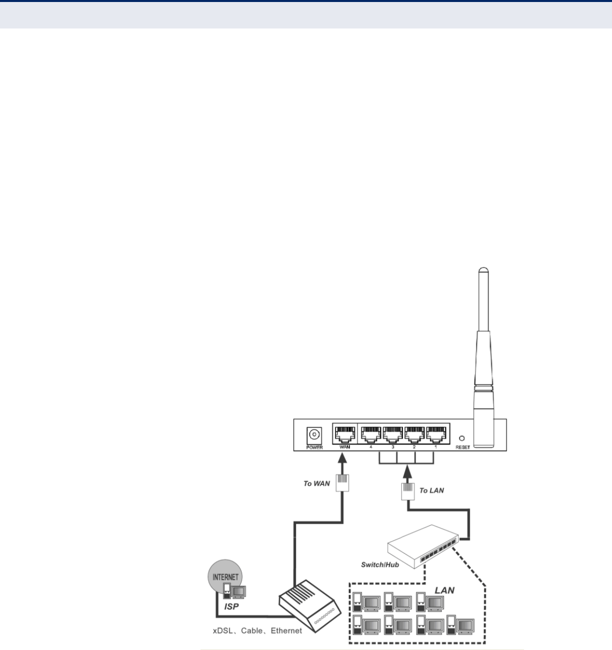
Connecting the Router
– 23 –
3. Adjust the direction of the antennas. Normally, upright is the best
direction.
4. Connect PCs and any switch in your LAN to the LAN Ports on the Router,
as shown in Figure 3.
5. Connect the DSL/Cable Modem to the WAN port on the Router, as
shown in Figure 3.
6. Connect the AC power adapter to the power socket on the Router, and
the other end into an electrical outlet. The Router will start to work
automatically.
7. Power on your PC and Cable/DSL Modem.
Figure 3: Hardware Installation

– 24 –
3QUICK INSTALLATION GUIDE
This chapter shows you how to quickly configure the basic functions of your
Router using the Quick Setup Wizard.
TCP/IP CONFIGURATION
The default IP address of the Router is 192.168.2.1. And the default
Subnet Mask is 255.255.255.0. These values can be changed as you
desire. In this guide, all the default values are used for descriptions.
Connect local PCs to the LAN ports of the Router. And then you can
configure the IP address for your PC in the following two ways.
CONFIGURE THE IP ADDRESS MANUALLY
1. Set up the TCP/IP Protocol for your PC. If you need instructions on how
to do this, refer to Appendix B: “Configuring the PC” on page 118.
2. Configure the network parameters. The IP address is 192.168.2.xxx
(“xxx” is any number from 2 to 254), Subnet Mask is 255.255.255.0,
and Gateway is 192.168.2.1 (the Router's default IP address).
OBTAIN AN IP ADDRESS AUTOMATICALLY
1. Set the TCP/IP Protocol to “Obtain an IP address automatically” mode
on your PC. If you need instructions as to how to do this, refer to
Appendix B: “Configuring the PC” on page 118.
2. Then the built-in DHCP server will assign IP address for the PC.
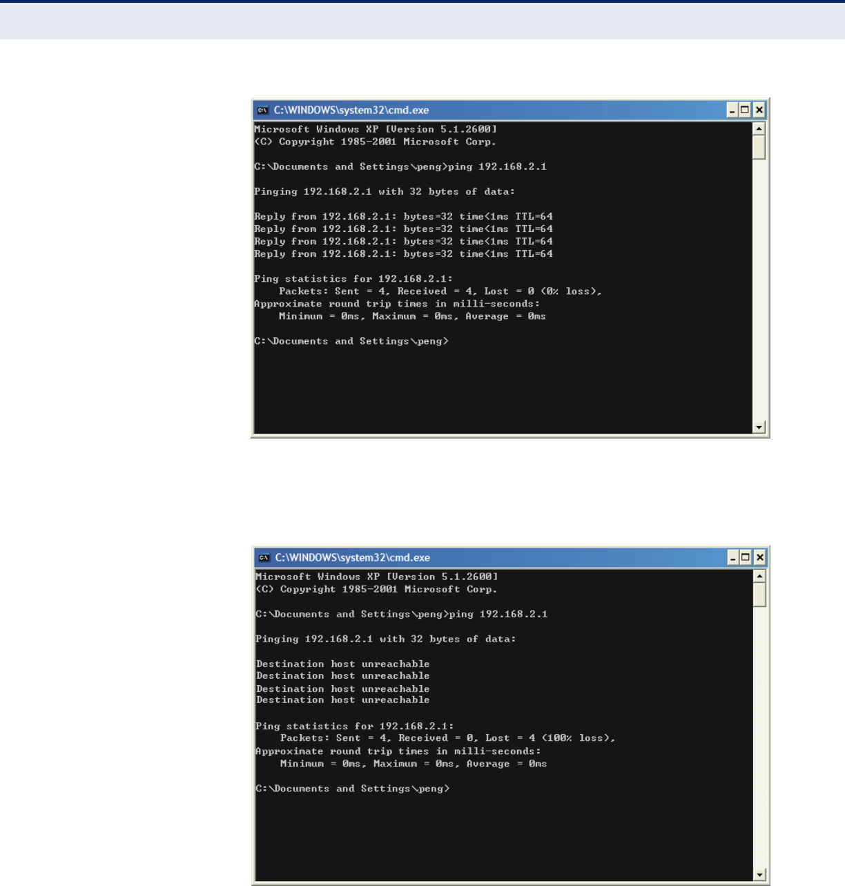
Now you can run the Ping command at the command prompt to verify the
network connection between your PC and the Router. The following
example is for Windows 2000.
Open a command prompt and type “ping 192.168.2.1”, and then press
Enter.
If the result displayed is similar to the Figure 4 on page 25, it means a
connection between your PC and the Router has been established.
C
HAPTER
3
| Quick Installation Guide
Quick Installation Guide
– 26 –
Follow these steps to check the connection:
1. Is the connection between your PC and the Router correct?
The LAN port LED on the Router and the LED on your PC's adapter
should be on.
2. Is the TCP/IP configuration for your PC correct?
If the Router's IP address is 192.168.2.1, your PC's IP address must be
within the range of 192.168.2.2 ~ 192.168.2.254.
QUICK INSTALLATION GUIDE
Using the Web-based utility, it is easy to configure and manage the Router.
The Web-based utility can be used on any Windows, Macintosh, or UNIX
system with a Web browser, such as Microsoft Internet Explorer, Mozilla
Firefox, or Apple Safari.
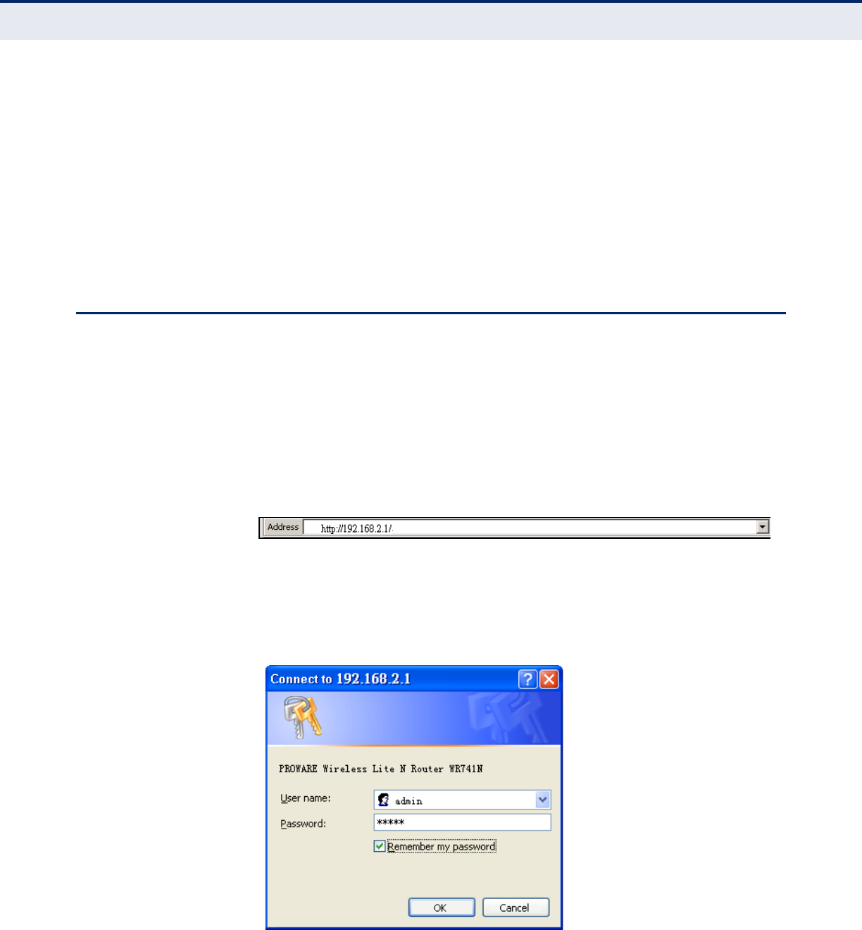
1. To access the configuration utility, open a web-browser and type in the
default address http://192.168.2.1 in the address field of the browser.
Figure 6: Log in to the Router
After a moment, a login window appears similar to Figure 7. Enter “admin”
for the User Name and “smcadmin” for the Password, both in lower case
letters. Then click the OK button or press the Enter key.
Figure 7: Windows Login
C
HAPTER
3
| Quick Installation Guide
Quick Installation Guide
– 27 –
N
OTE
:
If the above screen does not display, it means that your Web-
browser has been set to a proxy. Go to Tools menu>Internet
Options>Connections>LAN Settings, and in the screen that displays,
cancel the “Using Proxy” checkbox, and click OK.
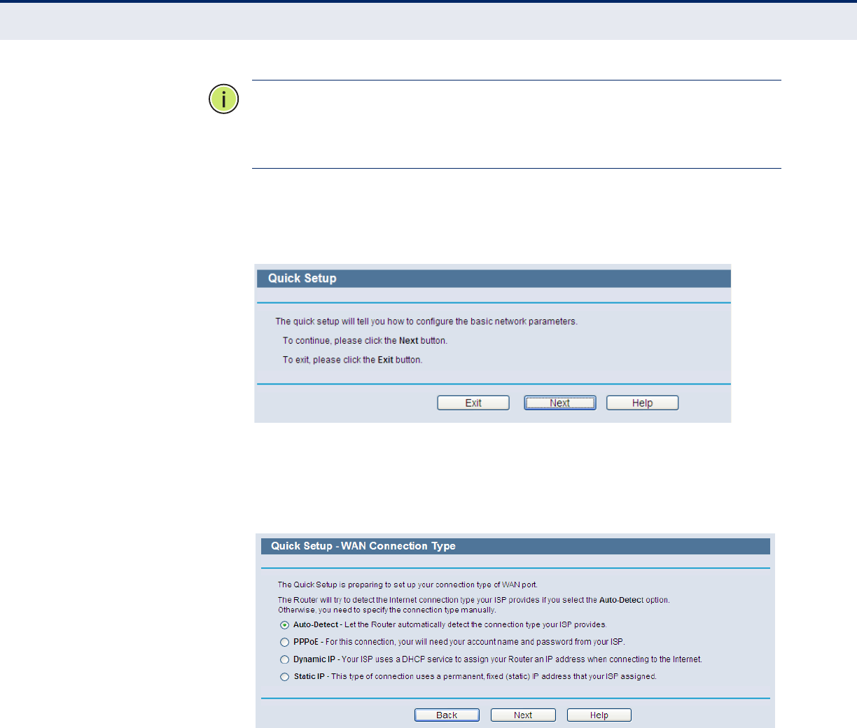
2. After successfully logging in, click “Quick Setup” to quickly configure
your Router.
Figure 8: Quick Setup
3. Click Next. The WAN Connection Type page will appear, as shown in
Figure 9.
Figure 9: Choose the WAN Connection Type
The Router provides an auto-detect function and supports three popular
ways (PPPoE, Dynamic IP, and Static IP) to connect to the Internet. It is
recommended that you make use of the auto-detect function. If you are
sure of what kind of connection type your ISP provides, you can select the
type and click Next to go on configuring.
4. If you select auto-detect, the Router will automatically detect the
connection type your ISP provides. Make sure the cable is securely
plugged into the WAN port before detection. The appropriate
configuration page will be displayed when an active Internet service is
successfully detected by the Router.
C
HAPTER
3
| Quick Installation Guide
Quick Installation Guide
– 28 –
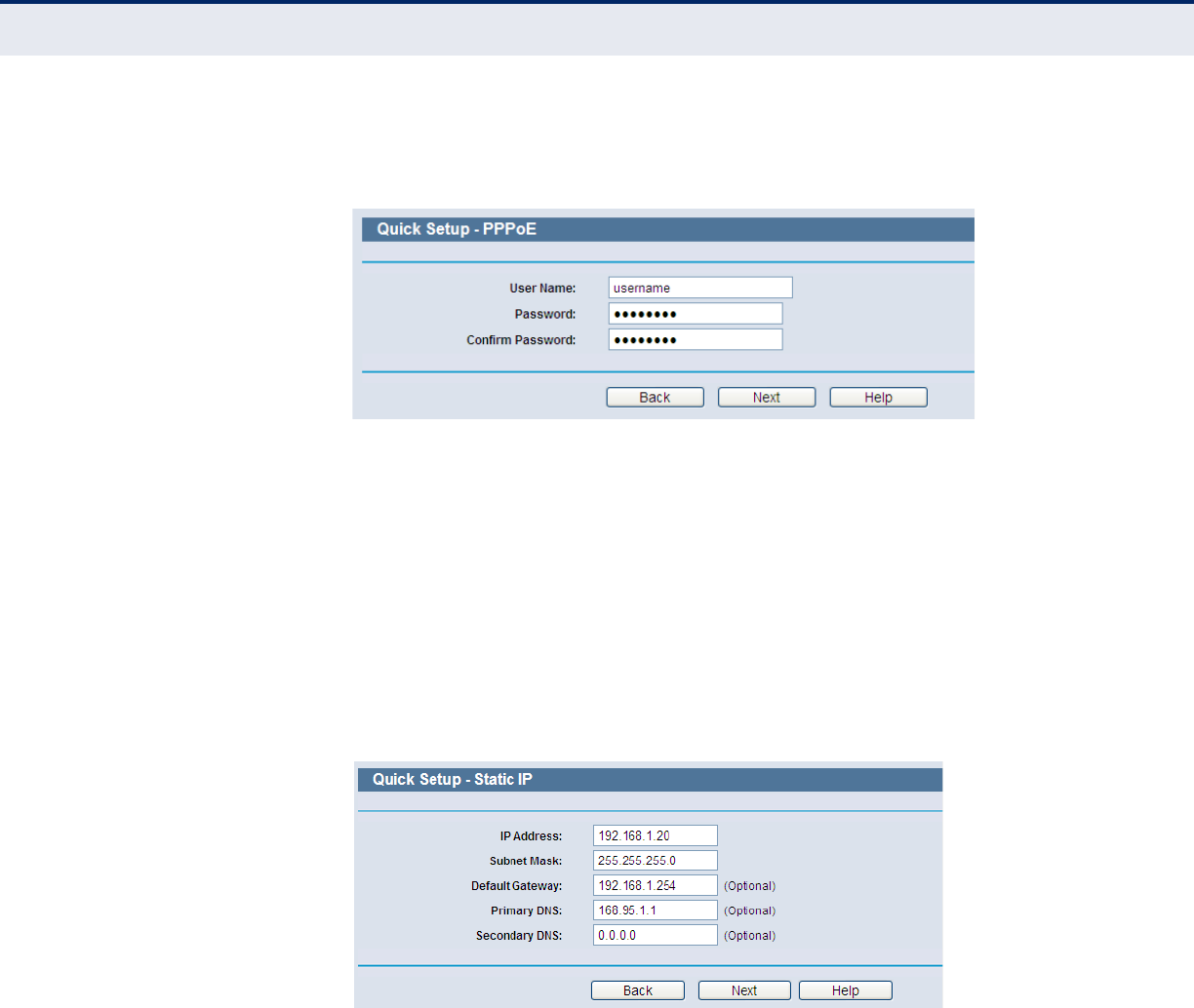
a. If the connection type detected is PPPoE, the screen shown in
Figure 10 will display.
Figure 10: Quick Setup – PPPoE
●User Name and Password — Enter the User Name and
Password provided by your ISP. These fields are case sensitive.
If you have difficulty with this process, contact your ISP.
b. If the connection type detected is Dynamic IP, the screen shown in
Figure 12 will display. You can then continue with the wireless
configuration.
c. If the connection type detected is Static IP, the screen shown in
Figure 11 will display.
Figure 11: Quick Setup - Static IP
●IP Address - This is the WAN IP address as seen by external
users on the Internet (including your ISP). Enter the IP address
into the field.
●Subnet Mask - The Subnet Mask is used for the WAN IP
address, it is usually 255.255.255.0.
●Default Gateway - Enter the gateway IP address into the box,
if required.
●Primary DNS - Enter the DNS Server IP address into the box, if
required.
C
HAPTER
3
| Quick Installation Guide
Quick Installation Guide
– 29 –
●Secondary DNS - If your ISP provides another DNS server,
enter it into this field.
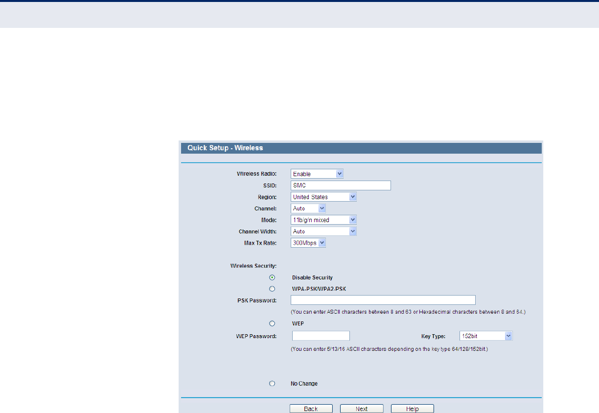
5. Click Next to continue. The Wireless settings page will appear, as shown
in Figure 12.
Figure 12: Quick Setup – Wireless
■Wireless Radio - Enable or disable the wireless radio choosing
from the pull-down list.
■SSID - Enter a value of up to 32 characters. The same name of
SSID (Service Set Identification) must be assigned to all wireless
devices in your network. Considering your wireless network
security, the default SSID is set to “SMC”. This value is case-
sensitive. For example, “TEST” is NOT the same as “test”.
■Region - Select your region from the pull-down list. This field
specifies the region where the wireless function of the Router can be
used. It may be illegal to use the wireless function of the Router in a
region other than one of those specified in this field. If your country
or region is not listed, contact your local government agency for
assistance.
■Channel - This field determines which operating frequency will be
used. The default channel is set to Auto, so the AP will choose the
best channel automatically. It is not necessary to change the
wireless channel unless you notice interference problems with
another nearby access point.

C
HAPTER
3
| Quick Installation Guide
Quick Installation Guide
– 30 –
■Mode - This field determines the wireless mode in which the Router
works.
■Channel Width - Select any channel width from the pull-down list.
The default setting is automatic, which can adjust the channel width
for your clients automatically.
■Max Tx Rate - You can limit the maximum transmission rate of the
Router through this field.
■Disable Security - The wireless security function can be enabled or
disabled. If disabled, the wireless stations will be able to connect
the Router without encryption. It is recommended strongly that you
choose one of following options to enable security.
■WPA-PSK/WPA2-PSK - Select WPA based on pre-shared
passphrase.
●PSK Password - You can enter ASCII or Hexadecimal characters.
For ASCII, the key can be made up of any numbers 0 to 9 and
any letters A to Z, the length should be between 8 and 63
characters.
For Hexadecimal, the key can be made up of any numbers 0 to
9 and letters A to F, the length should be between 8 and 64
characters.
Please also note the key is case sensitive, this means that upper
and lower case keys will affect the outcome. It would also be a
good idea to write down the key and all related wireless security
settings.
■No Change - If you chose this option, wireless security
configuration will not change.
These settings are only for basic wireless parameters. For advanced
settings, please refer to “Wireless” on page 56.
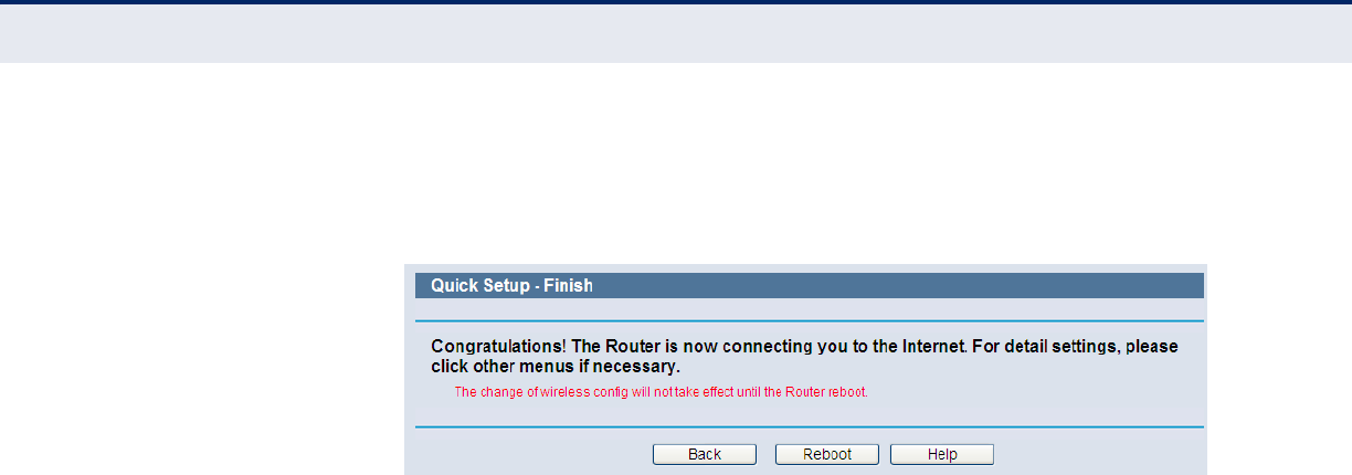
6. Click the Next button. You will then see the Finish page.
If you don’t make any changes on the Wireless page, you will see the
Finish page, as shown in Figure 13. Click the Finish button to finish
the Quick Setup.
Figure 13: Quick Setup – Finish
C
HAPTER
3
| Quick Installation Guide
Quick Installation Guide
– 31 –
If there is something changed on the Wireless page, you will see the
Finish page as shown in Figure 14. Click the Reboot button to make
your wireless configuration to take effect and finish the Quick Setup.
Figure 14: Quick Setup - Finish

– 32 –
4CONFIGURING THE ROUTER
This chapter shows each Web page's key functions and the configuration
method.
LOGIN
After successful login, you see the main menu on the left of the Web page.
On the right, there are the corresponding explanations and instructions.
Figure 15: The Main Menu
The detailed explanations for each Web page’s key functions are listed
below.
C
HAPTER
4
| Configuring the Router
Status
– 33 –
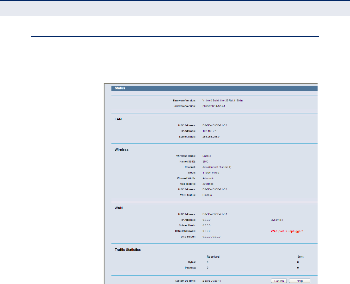
STATUS
The Status page provides the current status information about the Router.
All information is read-only.
Figure 16: Status
C
HAPTER
4
| Configuring the Router
Quick Setup
– 34 –
QUICK SETUP
Refer to “Quick Installation Guide” on page 24.
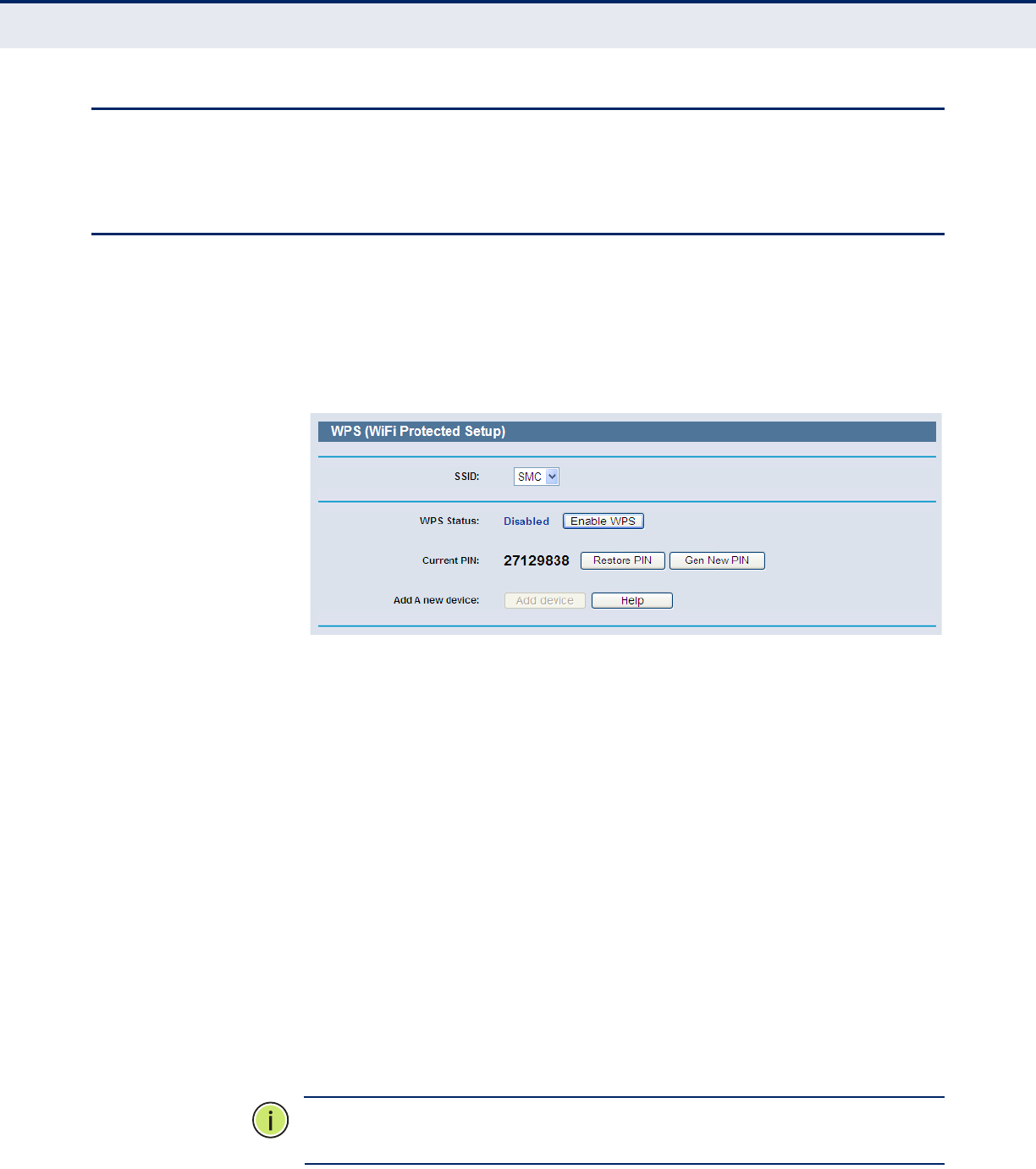
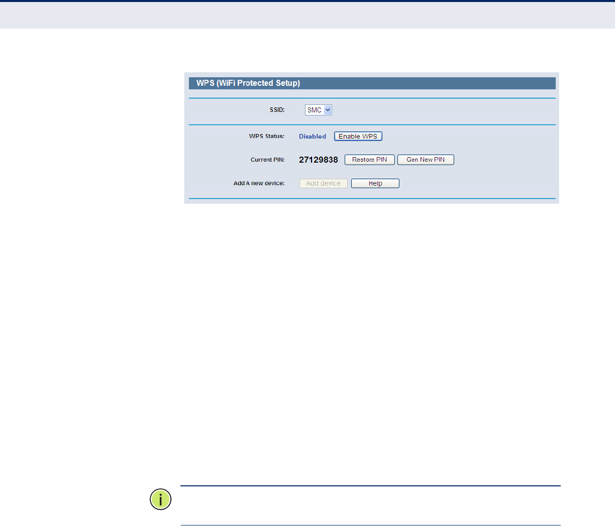
WPS
This section shows how to quickly add a new wireless device to an existing
network using WPS (Wi-Fi Protected Setup).
Select“WPS” from the menu. The following screen (Figure 17) displays.
Figure 17: WPS (Wi-Fi Protected Setup)
◆WPS Status - Enables or disables the WPS function.
◆Current PIN - Displays the current value of the Router's PIN. The
default PIN of the Router can be found on the label or in the User
Guide.
◆Restore PIN - Restores the PIN of the Router to its default value.
◆Gen New PIN - Click this button to create a new random value for the
Router's PIN. You can ensure the network security by generating a new
PIN.
◆Add device - You can manually add a new device to the existing
network by clicking this button.
ADDING A NEW
DEVICE:
If the wireless adapter supports Wi-Fi Protected Setup (WPS), you can
establish a wireless connection between wireless adapter and Router using
either the Push Button Configuration (PBC) method or the PIN method.
N
OTE
:
To make a successful connection using WPS, you should also
perform the corresponding WPS configuration on the new device.
C
HAPTER
4
| Configuring the Router
WPS
– 35 –
For the configuration of the new device, here takes the Wireless Adapter of
our company for example.
PUSH BUTTON CONFIGURATION (PBC)
If the wireless adapter supports Wi-Fi Protected Setup and the Push Button
Configuration (PBC) method, you can add it to the network by PBC with the
following two methods.
METHOD ONE:
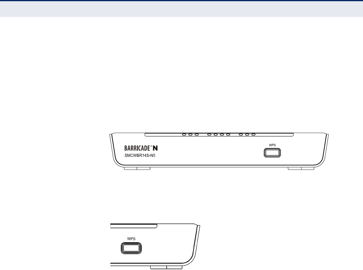
1. Press the WPS button on the front panel of the Router.
Figure 18: Front Panel
2. Press and hold the WPS button of the wireless client adapter directly for
2 or 3 seconds.
Figure 19: WPS Button
3. Wait a while until the next screen appears. Click Finish to complete the
WPS configuration.
C
HAPTER
4
| Configuring the Router
WPS
– 36 –
Figure 20: The WPS Configuration Screen of Wireless Adapter
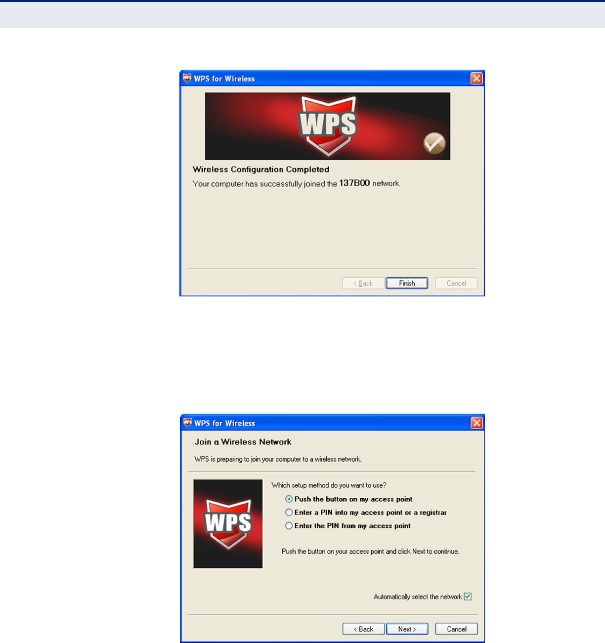
METHOD TWO:
1. Press the WPS button on the front panel of the Router.
2. To configure the wireless adapter, select “Push the button on my
access point” in the WPS configuration utility. Then click Next.
Figure 21: The WPS Configuration Screen of Wireless Adapter
C
HAPTER
4
| Configuring the Router
WPS
– 37 –
3. Wait until the next screen appears. Click Finish to complete the WPS
configuration.
Figure 22: The WPS Configuration Screen of Wireless Adapter
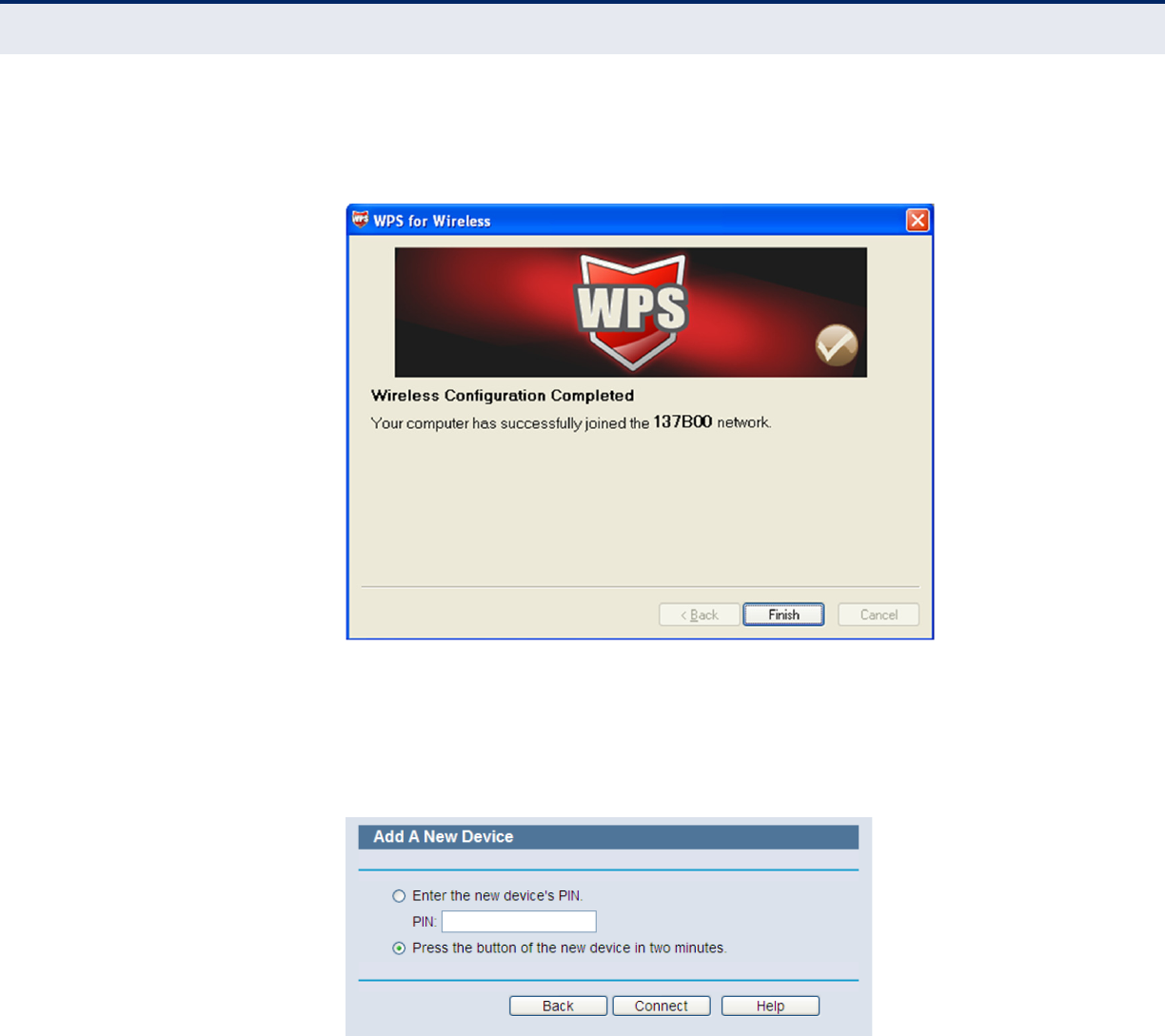
METHOD THREE:
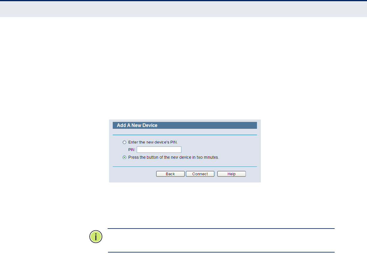
1. Keep the default WPS Status as Enabled and click the “Add device”
button in Figure 17, then the following screen will appear.
Figure 23: Add A New Device
2. Select “Press the button of the new device in two minutes” and
click Connect.
3. For the configuration of the wireless adapter, please choose “Push the
button on my access point” in the WPS configuration as below, and click
Next.

C
HAPTER
4
| Configuring the Router
WPS
– 38 –
Figure 24: The WPS Configuration Screen of Wireless Adapter
4. Wait until the next screen appears. Click Finish to complete the WPS
configuration.
Figure 25: The WPS Configuration Screen of Wireless Adapter
C
HAPTER
4
| Configuring the Router
WPS
– 39 –
PIN CONFIGURATION
If the new device supports Wi-Fi Protected Setup and the PIN method, you
can add it to the network by PIN with the following two methods.
METHOD ONE:
Enter the PIN into the Router.
1. Keep the default WPS Status as Enabled and click the “Add device”
button in Figure 17. The following screen will appear.
Figure 26: Add Device
2. Select “Enter the new device's PIN” and enter the PIN code of the
wireless adapter in the field after PIN, as shown in the figure above.
Then click Connect.
N
OTE
:
The PIN code of the adapter is always displayed on the WPS
configuration screen.
3. For the configuration of the wireless adapter, select “Enter a PIN into
my access point or a registrar” in the WPS configuration, and click
Next.

C
HAPTER
4
| Configuring the Router
WPS
– 40 –
Figure 27: The WPS Configuration Screen of Wireless Adapter
N
OTE
:
In this example, the default PIN code of this adapter is 16952898, as
shown in the above figure.
METHOD TWO:
Enter the PIN from my Router.
1. Read the Current PIN code of the Router in Figure 28. (This example
uses a PIN code 12345670 for the Router.)
2. For the configuration of the wireless adapter, select “Enter a PIN from
my access point” in the WPS configuration as below. Enter the PIN code
of the Router into the field after “Access Point PIN”. Then click Next.

C
HAPTER
4
| Configuring the Router
WPS
– 41 –
Figure 28: The WPS Configuration Screen of Wireless Adapter
N
OTE
:
The default PIN code of the Router can be found on its label or in the
WPS configuration screen, as in Figure 17.
You will see the following screen when the new device is successfully
connected to the network.
Figure 29: Add a New Device
N
OTE
:
The WPS LED on the Router will turn on green for five minutes when
a device has been successfully added to the network.
N
OTE
:
The WPS function cannot be configured when the wireless function
of the Router is disabled. Make sure the wireless function is enabled before
configuring WPS.
C
HAPTER
4
| Configuring the Router
Network
– 42 –
NETWORK
There are five submenus under the Network menu (shown in Figure 30):
WAN, MAC Clone, LAN, Dynamic DNS, and MAC Clone. Click any of
them to configure the corresponding function.
Figure 30: The Network Menu
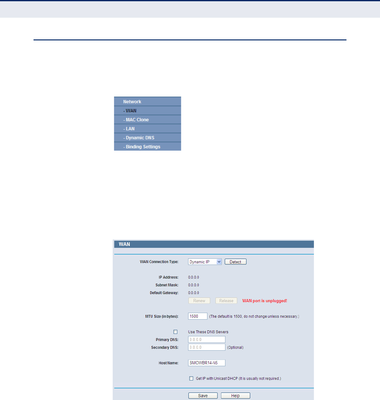
WAN Select “Network>WAN”, you can configure the IP parameters of the WAN
on the screen below.
1. If your ISP provides the DHCP service, choose Dynamic IP, and the
Router will automatically receive IP parameters from your ISP. You can
see the page as follows (Figure 31).
Figure 31: WAN-Dynamic IP
This page displays the WAN IP parameters assigned dynamically by your
ISP, including IP address, Subnet Mask, Default Gateway, etc. Click the
C
HAPTER
4
| Configuring the Router
Network
– 43 –
Renew button to renew the IP parameters from your ISP. Click the Release
button to release the IP parameters.
◆MTU Size - The normal MTU (Maximum Transmission Unit) value for
most Ethernet networks is 1500 Bytes. It is not recommended that you
change the default MTU Size unless required by your ISP.
◆Use These DNS Servers - If your ISP gives you one or two DNS
addresses, select Use These DNS Servers and enter the primary and
secondary addresses into the correct fields. Otherwise, the DNS servers
will be assigned dynamically from your ISP.
N
OTE
:
If you find an error when you go to a Web site after entering the
DNS addresses, it is likely that your DNS servers are set up improperly. You
should contact your ISP to check the DNS server addresses.
◆Get IP with Unicast DHCP - Some ISP DHCP servers do not support
broadcast applications. If you cannot get the IP Address normally, you
can choose this option. (It is rarely required.)
Click the Save button to save your settings.
2. If your ISP provides a static or fixed IP Address, Subnet Mask, Gateway
and DNS setting, select Static IP. The Static IP settings page will
appear, shown in Figure 32.
Figure 32: WAN-Static IP
◆IP Address - Enter the IP address in dotted-decimal notation provided
by your ISP.
◆Subnet Mask - Enter the subnet Mask in dotted-decimal notation
provided by your ISP, usually is 255.255.255.0.
C
HAPTER
4
| Configuring the Router
Network
– 44 –
◆Default Gateway - (Optional) Enter the gateway IP address in dotted-
decimal notation provided by your ISP.
◆MTU Size - The normal MTU (Maximum Transmission Unit) value for
most Ethernet networks is 1500 Bytes. It is not recommended that you
change the default MTU Size unless required by your ISP.
◆Primary/Secondary DNS - (Optional) Enter one or two DNS
addresses in dotted-decimal notation provided by your ISP.
Click the Save button to save your settings.
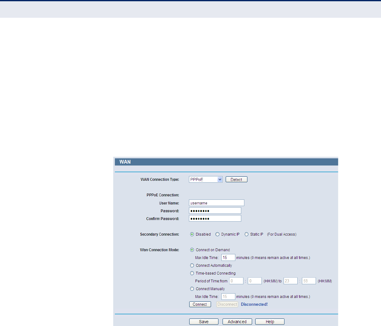
3. If your ISP provides a PPPoE connection, select PPPoE option. And you
should enter the following parameters (Figure 33):
Figure 33: WAN-PPPoE
◆User Name/Password - Enter the User Name and Password provided
by your ISP. These fields are case-sensitive.
◆Secondary Connection - It is available only for PPPoE Connection. If
your ISP provides an extra Connection type such as Dynamic/Static IP
to connect to a local area network, then you can check the radio button
of Dynamic/Static IP to activate this secondary connection.
■Disabled - The Secondary Connection is disabled by default, so
there is PPPoE connection only. This is recommended.
C
HAPTER
4
| Configuring the Router
Network
– 45 –
■Dynamic IP - You can check this radio button to use Dynamic IP as
the secondary connection to connect to the local area network
provided by ISP.
■Static IP - You can check this radio button to use Static IP as the
secondary connection to connect to the local area network provided
by ISP.
◆Connect on Demand - In this mode, the Internet connection can be
terminated automatically after a specified inactivity period (Max Idle
Time) and be re-established when you attempt to access the Internet
again. If you want your Internet connection keeps active all the time,
please enter “0” in the Max Idle Time field. Otherwise, enter the
number of minutes you want to have elapsed before your Internet
access disconnects.
◆Connect Automatically - The connection can be re-established
automatically when it was down.
◆Time-based Connecting - The connection will only be established in
the period from the start time to the end time (both are in HH:MM
format).
N
OTE
:
Only when you have configured the system time on System Tools ->
Time page, will the Time-based Connecting function can take effect.
◆Connect Manually - You can click the Connect/ Disconnect button to
connect/disconnect immediately. This mode also supports the Max Idle
Time function as Connect on Demand mode. The Internet connection
can be disconnected automatically after a specified inactivity period and
re-established when you attempt to access the Internet again.
C
AUTION
:
Sometimes the connection cannot be terminated although you
specify a time to Max Idle Time, since some applications are visiting the
Internet continually in the background.
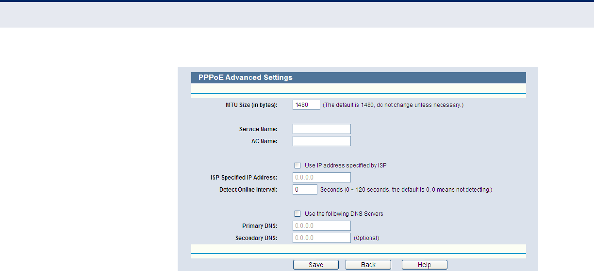
4. If you want to do some advanced configurations, please click the
Advanced button, and the page shown in Figure 34 will then appear:
C
HAPTER
4
| Configuring the Router
Network
– 46 –
Figure 34: WAN-PPPoE Advanced Settings
◆MTU Size - The default MTU size is “1480” bytes, which is usually fine.
It is not recommended that you change the default MTU Size unless
required by your ISP.
◆Service Name/AC Name - The service name and AC (Access
Concentrator) name, which should not be configured unless you are
sure it is necessary for your ISP. In most cases, leaving these fields
blank will work.
◆ISP Specified IP Address - If your ISP does not automatically assign
IP addresses to the Router during login, please click “Use IP address
specified by ISP” check box and enter the IP address provided by your
ISP in dotted-decimal notation.
◆Detect Online Interval - The Router will detect Access Concentrator
online at every interval. The default value is “0”. You can input the
value between “0”and “120”. The value “0” means no detect.
◆DNS IP address - If your ISP does not automatically assign DNS
addresses to the Router during login, please click “Use the following
DNS servers” check box and enter the IP address in dotted-decimal
notation of your ISP’s primary DNS server. If a secondary DNS server
address is available, enter it as well.
Click the Save button to save your settings.
5. If your ISP provides BigPond Cable (or Heart Beat Signal) connection,
please select BigPond Cable. And you should enter the following
parameters (Figure 35):
C
HAPTER
4
| Configuring the Router
Network
– 47 –
Figure 35: WAN-BigPond Cable
◆User Name/Password - Enter the User Name and Password provided
by your ISP. These fields are case-sensitive.
◆Auth Server - Enter the authenticating server IP address or host
name.
◆Auth Domain - Type in the domain suffix server name based on your
location.
For example:
NSW / ACT - nsw.bigpond.net.au
VIC / TAS / WA / SA / NT - vic.bigpond.net.au
QLD - qld.bigpond.net.au
◆MTU Size - The normal MTU (Maximum Transmission Unit) value for
most Ethernet networks is 1500 Bytes. It is not recommended that you
change the default MTU Size unless required by your ISP.
◆Connect on Demand - In this mode, the Internet connection can be
terminated automatically after a specified inactivity period (Max Idle
Time) and be re-established when you attempt to access the Internet
again. If you want your Internet connection keeps active all the time,
please enter “0” in the Max Idle Time field. Otherwise, enter the
number of minutes you want to have elapsed before your Internet
access disconnects.
◆Connect Automatically - The connection can be re-established
automatically when it was down.
C
HAPTER
4
| Configuring the Router
Network
– 48 –
◆Connect Manually - You can click the Connect/Disconnect button to
connect/disconnect immediately. This mode also supports the Max Idle
Time function as Connect on Demand mode. The Internet connection
can be disconnected automatically after a specified inactivity period and
re-established when you attempt to access the Internet again. Click the
Connect button to connect immediately. Click the Disconnect button to
disconnect immediately.
C
AUTION
:
Sometimes the connection cannot be terminated although you
specify a time to Max Idle Time because some applications are visiting the
Internet continually in the background.
6. If your ISP provides L2TP connection, please select L2TP option. And
you should enter the following parameters (Figure 36):
Figure 36: WAN-L2TP
◆User Name/Password - Enter the User Name and Password provided
by your ISP. These fields are case-sensitive.
◆Dynamic IP/ Static IP - Choose either as you are given by your ISP.
Click the Connect button to connect immediately. Click the Disconnect
button to disconnect immediately.
C
HAPTER
4
| Configuring the Router
Network
– 49 –
◆Connect on Demand - You can configure the Router to disconnect
from your Internet connection after a specified period of inactivity
(Max Idle Time). If your Internet connection has been terminated due
to inactivity, Connect on Demand enables the Router to automatically
re-establish your connection as soon as you attempt to access the
Internet again. If you wish to activate Connect on Demand, click the
radio button. If you want your Internet connection to remain active at
all times, enter 0 in the Max Idle Time field. Otherwise, enter the
number of minutes you want to have elapsed before your Internet
connection terminates.
◆Connect Automatically - Connect automatically after the Router is
disconnected. To use this option, click the radio button.
◆Connect Manually - You can configure the Router to make it connect
or disconnect manually. After a specified period of inactivity (Max Idle
Time), the Router will disconnect from your Internet connection, and
you will not be able to re-establish your connection automatically as
soon as you attempt to access the Internet again. To use this option,
click the radio button. If you want your Internet connection to remain
active at all times, enter "0" in the Max Idle Time field. Otherwise,
enter the number in minutes that you wish to have the Internet
connecting last unless a new link is requested.
C
AUTION
:
Sometimes the connection cannot be disconnected although you
specify a time to Max Idle Time, since some applications is visiting the
Internet continually in the background.
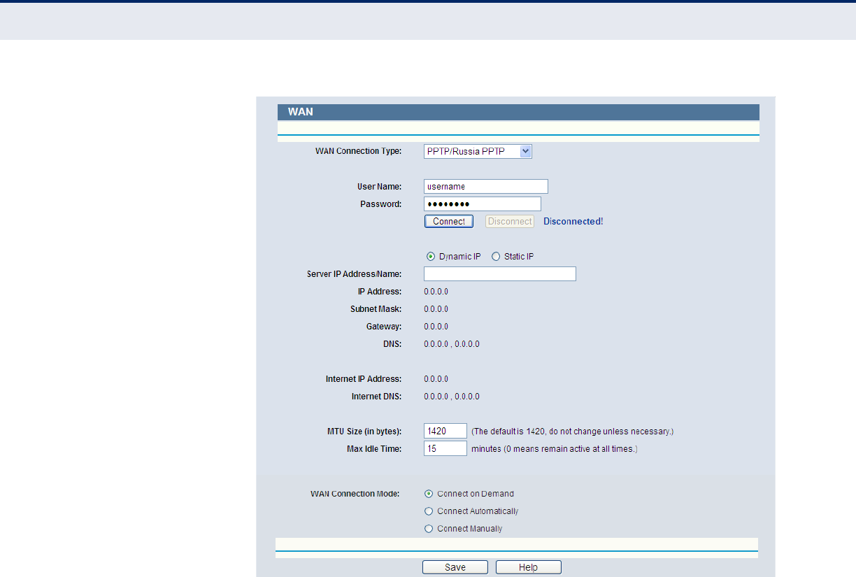
7. If your ISP provides PPTP connection, please select PPTP option. And
you should enter the following parameters (Figure 37):
C
HAPTER
4
| Configuring the Router
Network
– 50 –
Figure 37: WAN-PPTP
◆User Name/Password - Enter the User Name and Password provided
by your ISP. These fields are case-sensitive.
◆Dynamic IP/ Static IP - Choose either as you are given by your ISP
and enter the ISP’s IP address or the domain name. If you choose static
IP and enter the domain name, you should also enter the DNS assigned
by your ISP. And click the Save button. Click the Connect button to
connect immediately. Click the Disconnect button to disconnect
immediately.
◆Connect on Demand - You can configure the Router to disconnect
from your Internet connection after a specified period of inactivity (Max
Idle Time). If your Internet connection has been terminated due to
inactivity, Connect on Demand enables the Router to automatically re-
establish your connection as soon as you attempt to access the Internet
again. If you wish to activate Connect on Demand, click the radio
button. If you want your Internet connection to remain active at all
times, enter 0 in the Max Idle Time field. Otherwise, enter the number
of minutes you want to have elapsed before your Internet connection
terminates.
◆Connect Automatically - Connect automatically after the Router is
disconnected. To use this option, click the radio button.
C
HAPTER
4
| Configuring the Router
Network
– 51 –
◆Connect Manually - You can configure the Router to make it connect
or disconnect manually. After a specified period of inactivity (Max Idle
Time), the Router will disconnect from your Internet connection, and
you will not be able to re-establish your connection automatically as
soon as you attempt to access the Internet again. To use this option,
click the radio button. If you want your Internet connection to remain
active at all times, enter "0" in the Max Idle Time field. Otherwise,
enter the number in minutes that you wish to have the Internet
connecting last unless a new link is requested.
C
AUTION
:
Sometimes the connection cannot be disconnected although you
specify a time to Max Idle Time, since some applications are visiting the
Internet continually in the background.
N
OTE
:
If you do not know how to choose the appropriate connection type,
click the Detect button to allow the Router to automatically search your
Internet connection for servers and protocols. The connection type will be
reported when an active Internet service is successfully detected by the
Router. This report is for your reference only. To make sure the connection
type your ISP provides, please refer to the ISP. The various types of
Internet connections that the Router can detect are as follows:
■PPPoE - Connections which use PPPoE that requires a user name
and password.
■Dynamic IP - Connections which use dynamic IP address
assignment.
■Static IP - Connections which use static IP address assignment.
The Router can not detect PPTP/L2TP/BigPond connections with your ISP. If
your ISP uses one of these protocols, then you must configure your
connection manually.
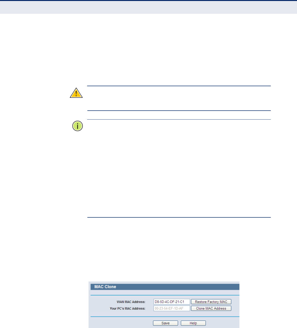
MAC CLONE Choose menu “Network->MAC Clone”, you can configure the MAC
address of the WAN on the screen below, Figure :
Figure 38: MAC Address Clone
C
HAPTER
4
| Configuring the Router
Network
– 52 –
Some ISPs require that you register the MAC Address of your adapter.
Changes are rarely needed here.
◆WAN MAC Address - This field displays the current MAC address of
the WAN port. If your ISP requires you to register the MAC address,
please enter the correct MAC address into this field in XX-XX-XX-XX-XX-
XX format (X is any hexadecimal digit).
◆Your PC's MAC Address - This field displays the MAC address of the
PC that is managing the Router. If the MAC address is required, you can
click the Clone MAC Address To button and this MAC address will fill in
the WAN MAC Address field.
Click Restore Factory MAC to restore the MAC address of WAN port to the
factory default value.
Click the Save button to save your settings.
N
OTE
:
Only the PC on your LAN can use the MAC Address Clone function.
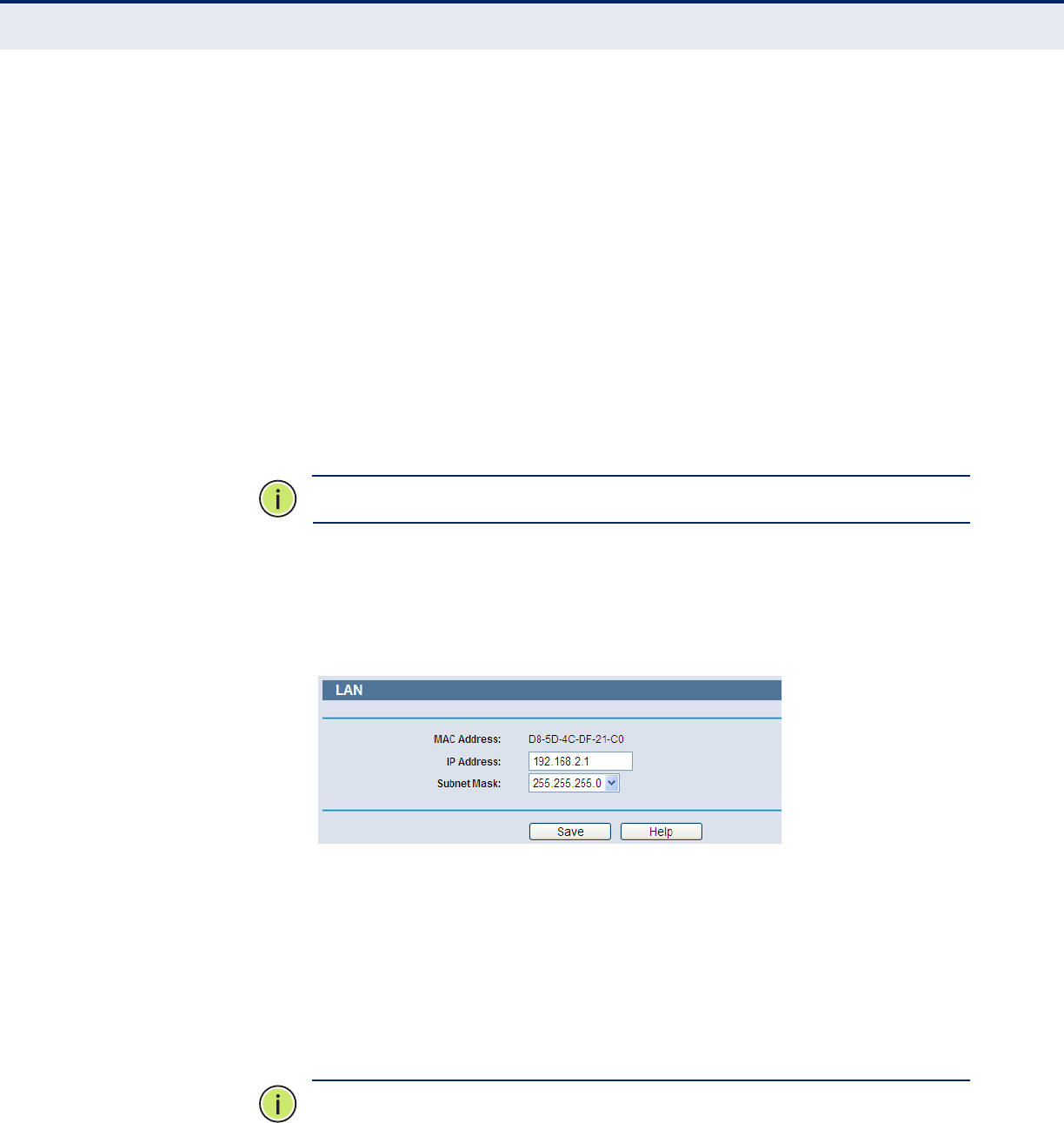
LAN Choose menu “Network-> LAN”, you can configure the IP parameters of
the LAN on the screen as below.
Figure 39: LAN
◆MAC Address - The physical address of the Router, as seen from the
LAN. The value cannot be changed.
◆IP Address - Enter the IP address of your Router or reset it in dotted-
decimal notation (factory default: 192.168.2.1).
◆Subnet Mask - An address code that determines the size of the
network. Normally use 255.255.255.0 as the subnet mask.
N
OTE
:
If you change the IP Address of LAN, you must use the new IP
Address to login the Router.
C
HAPTER
4
| Configuring the Router
Network
– 53 –
N
OTE
:
If the new LAN IP Address you set is not in the same subnet, the IP
Address pool of the DHCP server will change accordingly at the same time,
while the Virtual Server and DMZ Host will not take effect until they are re-
configured.
DYNAMIC DNS Choose menu “Dynamic DNS”, and you can configure the Dynamic DNS
function.
The Router offers the DDNS (Dynamic Domain Name System) feature,
which allows the hosting of a website, FTP server, or e-mail server with a
fixed domain name (named by yourself) and a dynamic IP address, and
then your friends can connect to your server by entering your domain
name no matter what your IP address is. Before using this feature, you
need to sign up for DDNS service providers such as www.comexe.cn,
www.dyndns.org, or www.no-ip.com. The Dynamic DNS client service
provider will give you a password or key.
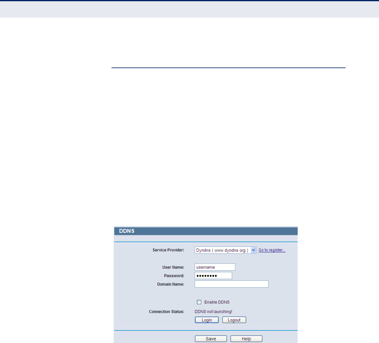
COMEXE.CN DDNS
If the dynamic DNS Service Provider you select is www.comexe.cn, the
page will appear as shown in Figure 40.
Figure 40: Dyndns.org DDNS Settings
To set up for DDNS, follow these instructions:
1. Type the Domain Name received from your dynamic DNS service
provider.
2. Type the User Name for your DDNS account.
3. Type the Password for your DDNS account.
4. Click the Login button to log in to the DDNS service.
C
HAPTER
4
| Configuring the Router
Network
– 54 –
◆Connection Status -The status of the DDNS service connection is
displayed here.
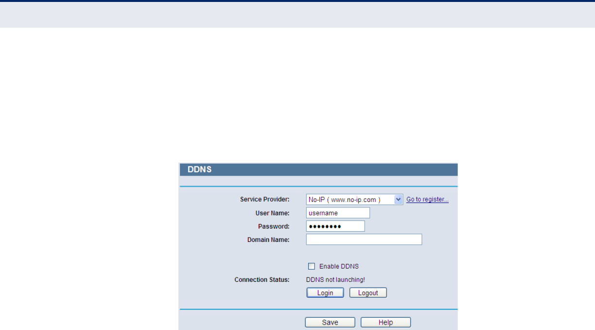
NO-IP.COM DDNS
If the dynamic DNS Service Provider you select is www.no-ip.com, the
page will appear as shown in Figure 41.
Figure 41: No-ip.com DDNS Settings
◆Connection Status - The status of the DDNS service connection is
displayed here.
◆Click Logout to log out the DDNS service.
To set up for DDNS, follow these instructions:
1. Type the User Name for your DDNS account.
2. Type the Password for your DDNS account.
3. Type the Domain Name you received from dynamic DNS service
provider.
4. Click the Login button to log in the DDNS service.
C
HAPTER
4
| Configuring the Router
Network
– 55 –
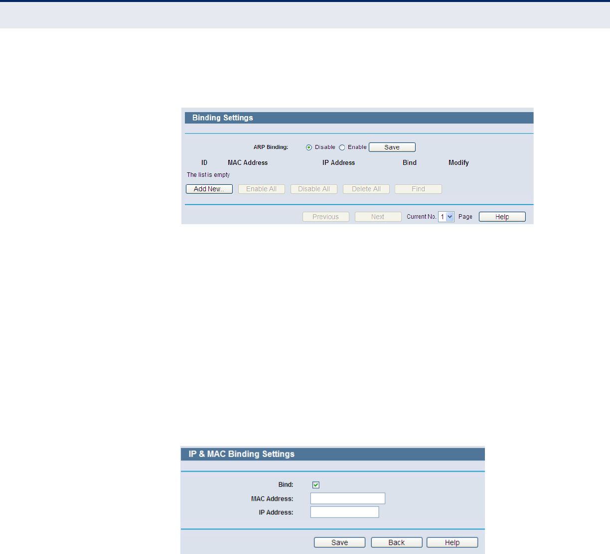
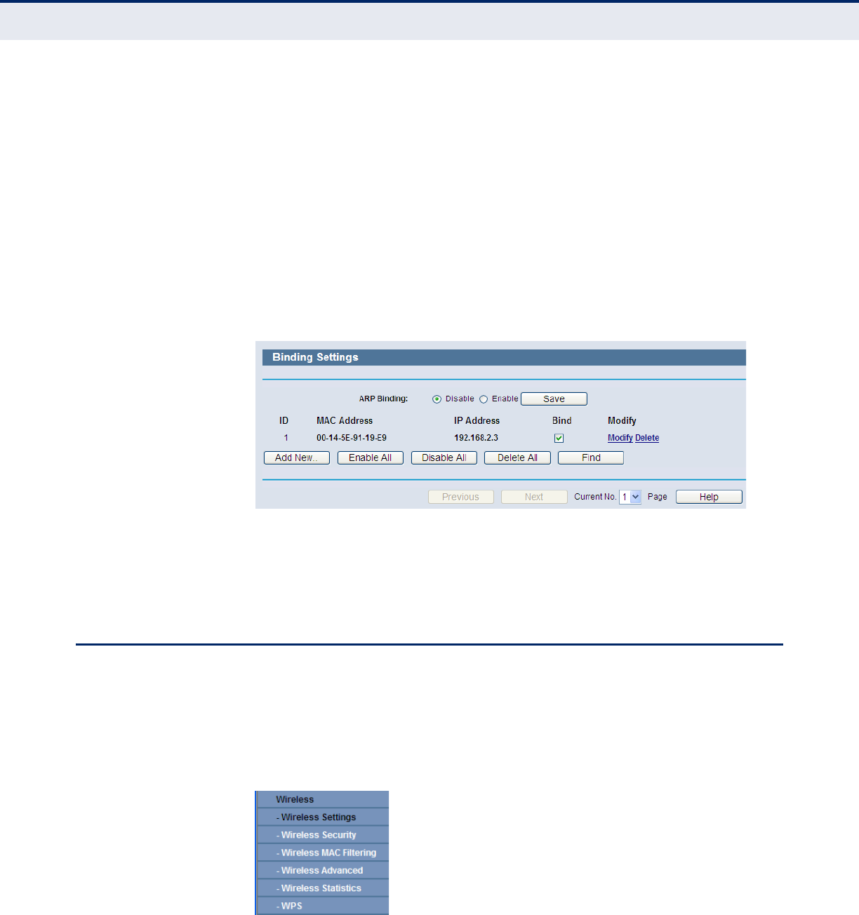
BINDING SETTING This page displays the IP & MAC Binding Setting table; you can
configure it as needed (as shown in Figure 42).
Figure 42: Binding Setting
◆MAC Address - The MAC address of the controlled computer in the
LAN.
◆IP Address - The assigned IP address of the controlled computer in
the LAN.
◆Bind - Check this option to enable ARP binding for a specific device.
◆Modify - To modify or delete an existing entry.
When you want to add or modify an IP & MAC Binding entry, you can click
the “Add New” button or “Modify” button, and then you will go to the next
page. This page is used for adding or modifying an IP & MAC Binding entry
(as shown in Figure 43).
Figure 43: IP & MAC Binding Setting (Add & Modify)
To add IP & MAC Binding entries, follow the steps below.
1. Click the Add New... button as shown in Figure 42.
2. Enter the MAC Address and IP Address.
3. Select the Bind checkbox.
4. Click the Save button to save it.
C
HAPTER
4
| Configuring the Router
Wireless
– 56 –
To modify or delete an existing entry, follow the steps below.
1. Find the desired entry in the table.
2. Click Modify or Delete in the Modify column.
To find an existing entry, follow the steps below.
1. Click the Find button as shown in Figure 44.
2. Enter the MAC Address or IP Address.
3. Click the Find button in the page as shown in Figure 44.
Figure 44: Find IP & MAC Binding Entry
Click the “Enable All” button to make all entries enabled.
Click the “Delete All” button to delete all entries.
WIRELESS
There are six submenus under the Wireless menu (shown in Figure 45):
Wireless Settings, Wireless Security, Wireless MAC Filtering,
Wireless Advanced, Wireless Statistics, and WPS. Click any of them,
and you will be able to configure the corresponding function.
Figure 45: Wireless Menu
C
HAPTER
4
| Configuring the Router
Wireless
– 57 –
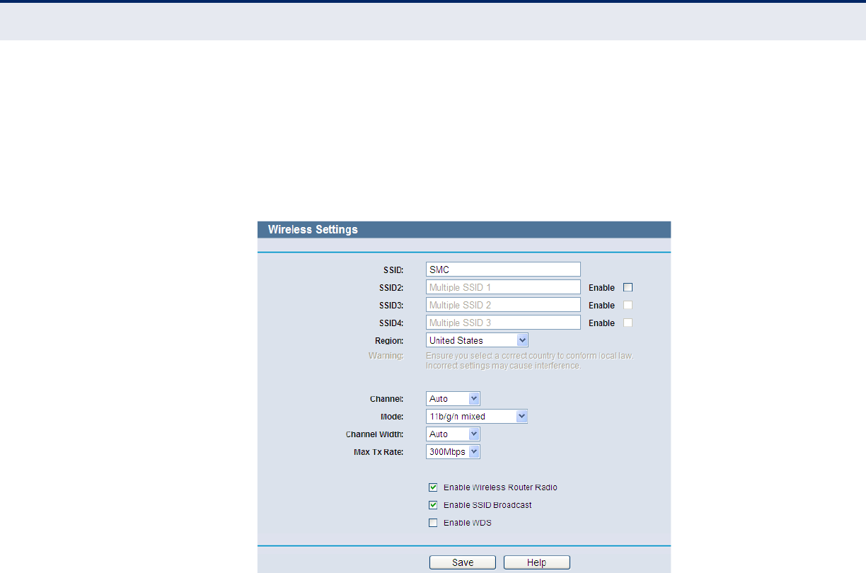
WIRELESS SETTINGS Choose menu Wireless -> Wireless Setting; you can configure the basic
settings for the wireless network on this page.
The wireless settings section displays configuration settings for the access
point functionality of the Wireless AP/router. It includes the following
sections:
Figure 46: Wireless Settings
◆SSID - Enter a value of up to 32 characters. The same SSID (Service
Set Identification) must be assigned to all wireless devices in your
network. The default SSID is set to be “SMC”. This value is case-
sensitive. For example, “TEST” is NOT the same as “test”.
◆SSID (2-4) - Up to four SSIDs for each BSS can be set, the names can
be up to 32 characters. The multi-SSID function is available only when
Enable is checked.
◆Region - Select your region from the pull-down list. This field specifies
the region where the wireless function of the Router can be used. It
may be illegal to use the wireless function of the Router in a region
other than one of those specified in this field. If your country or region
is not listed, please contact your local government agency for
assistance.
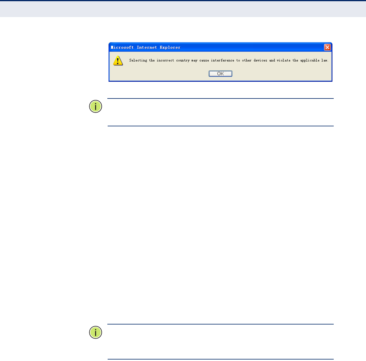
When you select your local region from the pull-down list, click the
Save button, then the Note Dialog appears. Click OK.
C
HAPTER
4
| Configuring the Router
Wireless
– 58 –
Figure 47: Note Dialog
N
OTE
:
Limited by local law regulations, the version for North America does
not have a region selection option.
◆Channel - This field determines which operating frequency will be used
for wireless operation. The default setting is Auto, so the AP will choose
the best channel automatically. It is not necessary to change the
wireless channel unless you notice interference problems with another
nearby access point.
◆Mode - Select the operating mode. The default is 11b/g/n mixed.
■11b only - Select if all of your wireless clients are 802.11b.
11g only - Select if all of your wireless clients are 802.11g.
11n only- Select only if all of your wireless clients are 802.11n.
11b/g mixed - Select if you are using both 802.11b and 802.11g
wireless clients.
11b/g/n mixed - Select if you are using a mix of 802.11b, 11g,
and 11n wireless clients.
When 802.11g mode is selected, only 802.11g wireless stations can
connect to the Router. When 802.11n mode is selected, only
802.11n wireless stations can connect to the Router. It is strongly
recommended to set the mode to 11b/g/n mixed, then all 802.11b,
802.11g, and 802.11n wireless stations can connect to the Router.
◆Channel width - Select any channel width from the pull-down list. The
default setting is automatic, which can adjust the channel width for
your clients automatically.
N
OTE
:
If 11b only, 11g only, or 11bg mixed is selected in the Mode field,
the Channel Width selecting field will turn grey and the value will become
20M, which cannot be changed.
◆Max Tx Rate - You can limit the maximum transmit rate of the Router
through this field.
◆Enable Wireless Router Radio - The wireless radio of this Router can
be enabled or disabled to allow wireless stations access.
◆Enable SSID Broadcast - When wireless clients survey the local area
for wireless networks to associate with, they will detect the SSID
C
HAPTER
4
| Configuring the Router
Wireless
– 59 –
broadcast by the Router. If you select the Enable SSID Broadcast
checkbox, the Wireless Router will broadcast its name (SSID) on the
air.
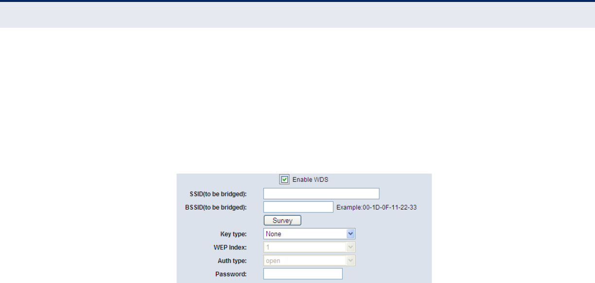
◆Enable WDS - Check this box to enable WDS. With this function, the
Router can bridge two or more WLANs. If this checkbox is selected, you
will have to set the following parameters as shown in Figure 48. Make
sure the following settings are correct.
Figure 48: Enable WDS
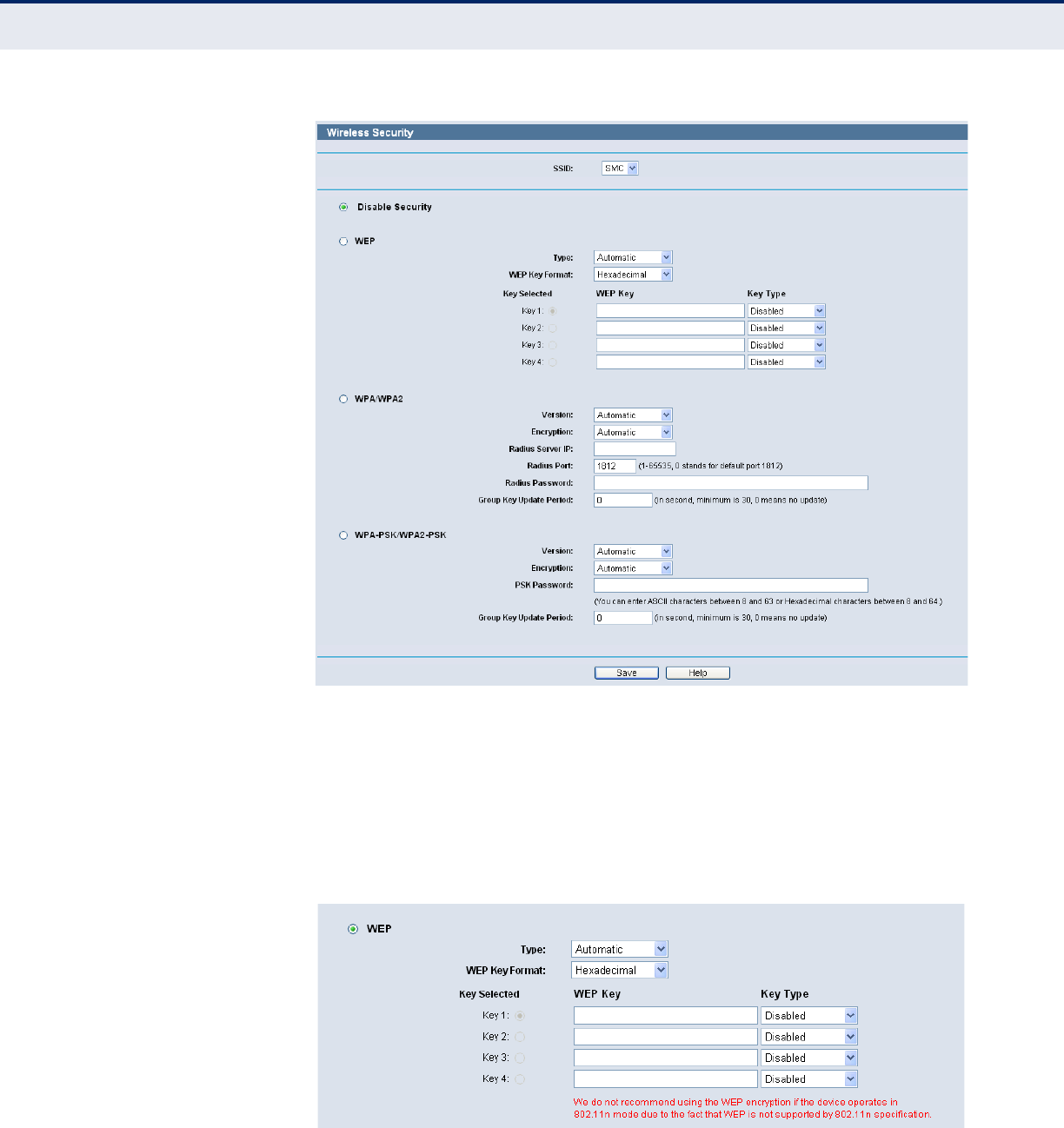
WIRELESS SECURITY Choose menu “Wireless->Wireless Security”; you can then configure
the security settings of your wireless network.
There are five wireless security modes supported by the Router: WEP
(Wired Equivalent Privacy), WPA (Wi-Fi Protected Access), WPA2 (Wi-Fi
Protected Access 2), WPA2-PSK (Pre-Shared Key), and WPA-PSK (Pre-
Shared Key).
C
HAPTER
4
| Configuring the Router
Wireless
– 60 –
Figure 49: Wireless Security
◆Disable Security - If you do not want to use wireless security, select
this check box. However, it is strongly recommended to choose one of
the following modes to enable security.
◆WEP - This security is based on the IEEE 802.11 standard. If you select
this check box, you will find a notice in red, as shown in Figure 50.
Figure 50: WEP
■Type - you can choose the type for the WEP security on the pull-
down list. The default setting is Automatic, which can select Open
C
HAPTER
4
| Configuring the Router
Wireless
– 61 –
System or Shared-Key authentication type automatically based on
the wireless station's capability and request.
■WEP Key Format - Hexadecimal and ASCII formats are provided.
Hexadecimal format stands for any combination of hexadecimal
digits (0-9, a-f, A-F) in the specified length. ASCII format stands for
any combination of keyboard characters in the specified length.
■WEP Key- Select which of the four keys will be used and enter the
matching WEP key that you create. Make sure these values are
identical on all wireless stations in your network.
■Key Type - You can select the WEP key length (64-bit, or 128-bit,
or 152-bit.) for encryption. "Disabled" means this WEP key entry is
invalid.
●64-bit - You can enter 10 hexadecimal digits (any combination
of 0-9, a-f, A-F, zero key is not promoted) or 5 ASCII characters.
128-bit - You can enter 26 hexadecimal digits (any combination
of 0-9, a-f, A-F, zero key is not promoted) or 13 ASCII
characters.
152-bit - You can enter 32 hexadecimal digits (any combination
of 0-9, a-f, A-F, zero key is not promoted) or 16 ASCII
characters.
N
OTE
:
If you do not set the key, the wireless security function is still
disabled even if you have selected Shared Key as the Authentication Type.
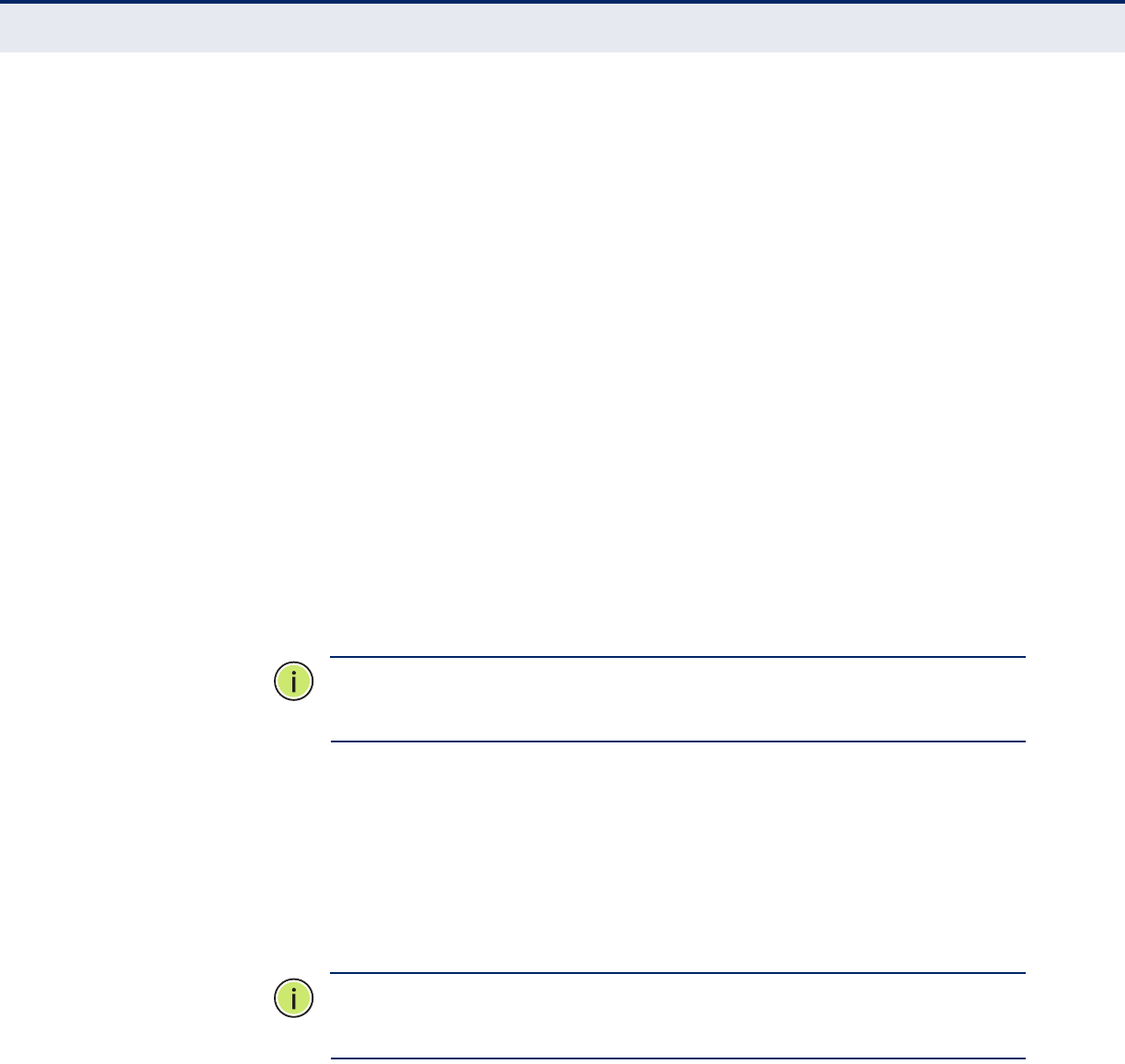
◆WPA /WPA2 - Authentication that uses a RADIUS Server.
■Version - you can choose the version of the WPA security on the
pull-down list. The default setting is Automatic, which can select
WPA (Wi-Fi Protected Access) or WPA2 (WPA version 2)
automatically based on the wireless station's capability and request.
■Encryption - You can select either Automatic, TKIP, or AES.
N
OTE
:
If you check the WPA/WPA2 radio button and choose TKIP
encryption, you will find a notice in red, as shown in Figure 51.
C
HAPTER
4
| Configuring the Router
Wireless
– 62 –
Figure 51: WPA/WPA2
■Radius Server IP - Enter the IP address of the RADIUS Server.
■Radius Port - Enter the port that the RADIUS service uses.
■Radius Password - Enter the password for the RADIUS server.
■Group Key Update Period - Specify the group key update interval
in seconds. The value should be 30 or above. Enter 0 to disable the
update.
◆WPA-PSK/WPA2-PSK - The WPA/WPA2 authentication type based on
a pre-shared passphrase.
■Version - You can choose the version of the WPA-PSK security from
the drop-down list. The default setting is Automatic, which can
select WPA-PSK (Pre-shared key of WPA) or WPA2-PSK (Pre-shared
key of WPA2) automatically based on the wireless station's
capability and request.
■Encryption - When WPA-PSK or WPA is set as the Authentication
Type, you can select either Automatic, TKIP, or AES as the
encryption type.
N
OTE
:
If you check the WPA-PSK/WPA2-PSK radio button and choose TKIP
encryption, you will find a notice in red, as shown in Figure 52.
Figure 52: WPA-PSK
■PSK Passphrase - You can enter between 8 and 63 ASCII
characters, or 8 to 64 Hexadecimal characters.
C
HAPTER
4
| Configuring the Router
Wireless
– 63 –
■Group Key Update Period - Specify the group key update interval
in seconds. The value should be 30 or above. Enter 0 to disable the
update.
Be sure to click the Save button to save your settings on this page.
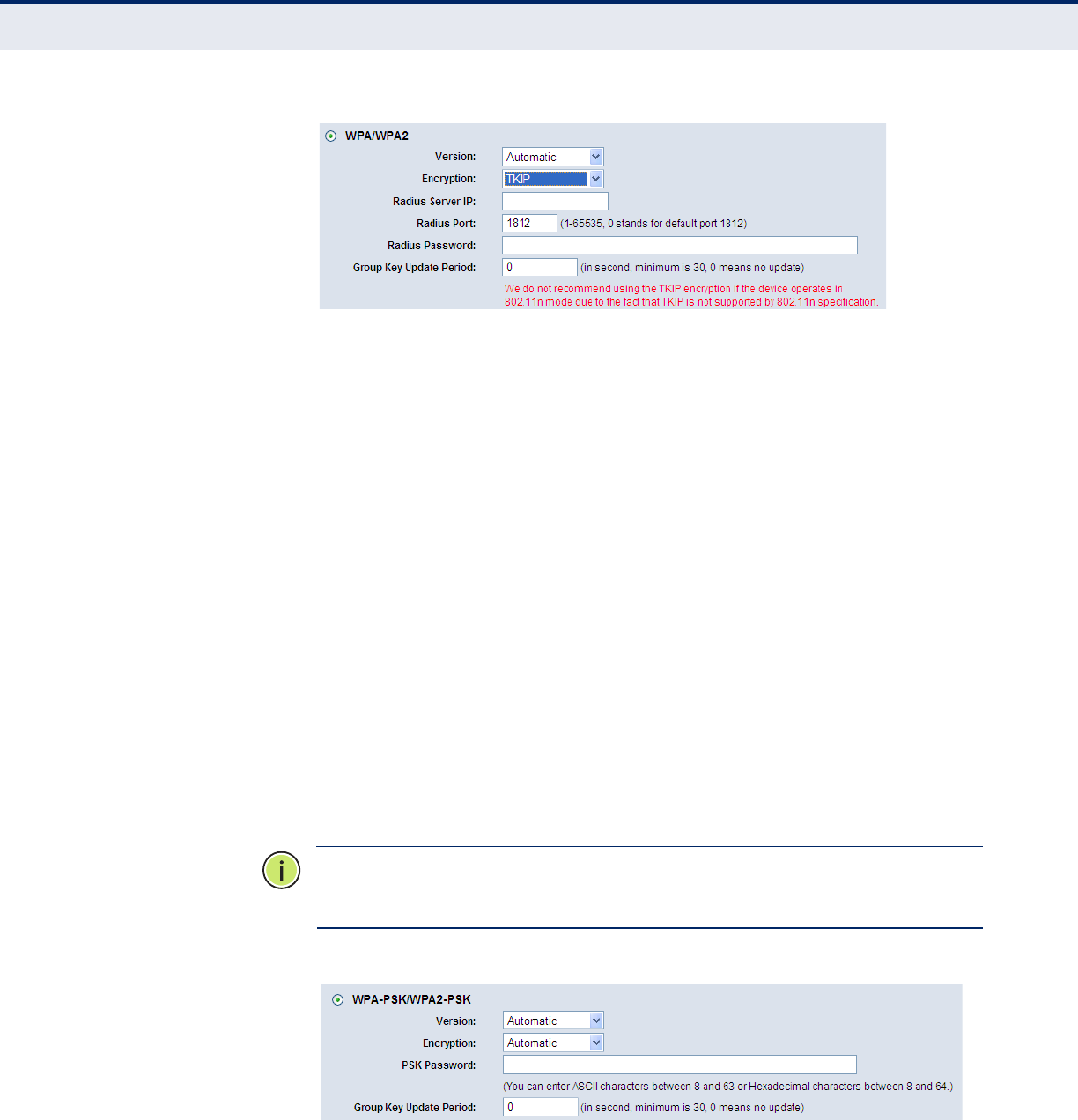
WIRELESS MAC
FILTERING
Choose Wireless -> MAC Filtering from the menu; you can then control
wireless access by configuring the Wireless MAC Address Filtering function,
as shown in Figure 53.
Figure 53: Wireless MAC Address Filtering
To filter wireless users by MAC Address, click Enable. The default setting is
Disable.
◆MAC Address - The wireless station's MAC address that you want to
filter.
◆Status - The status of this entry, either Enabled or Disabled.
◆Description - A simple description of the wireless station.
To Add a Wireless MAC Address filtering entry, click the “Add New” button.
The "Add or Modify Wireless MAC Address Filtering entry" page will appear,
as shown in Figure 54:

C
HAPTER
4
| Configuring the Router
Wireless
– 64 –
Figure 54: Add or Modify Wireless MAC Address Filtering Entry
To add or modify a MAC Address Filtering entry, follow these instructions:
1. Enter the appropriate MAC Address into the MAC Address field. The
format of the MAC Address is XX-XX-XX-XX-XX-XX (X is any
hexadecimal digit). For example: 00-0A-EB-00-07-8A.
2. Provide a simple description of the wireless station in the Description
field. For example: Wireless station A.
3. Select Enabled or Disabled for this entry on the Status pull-down list.
4. Click the Save button to save this entry.
To modify or delete an existing entry:
1. Click the Modify in the entry you want to modify. If you want to delete
the entry, click the Delete button.
2. Modify the information.
3. Click the Save button.
Click the Enable All button to make all entries enabled.
Click the Disabled All button to make all entries disabled.
Click the Delete All button to delete all entries.
Click the Next button to go to the next page.
Click the Previous button to return to the previous page.
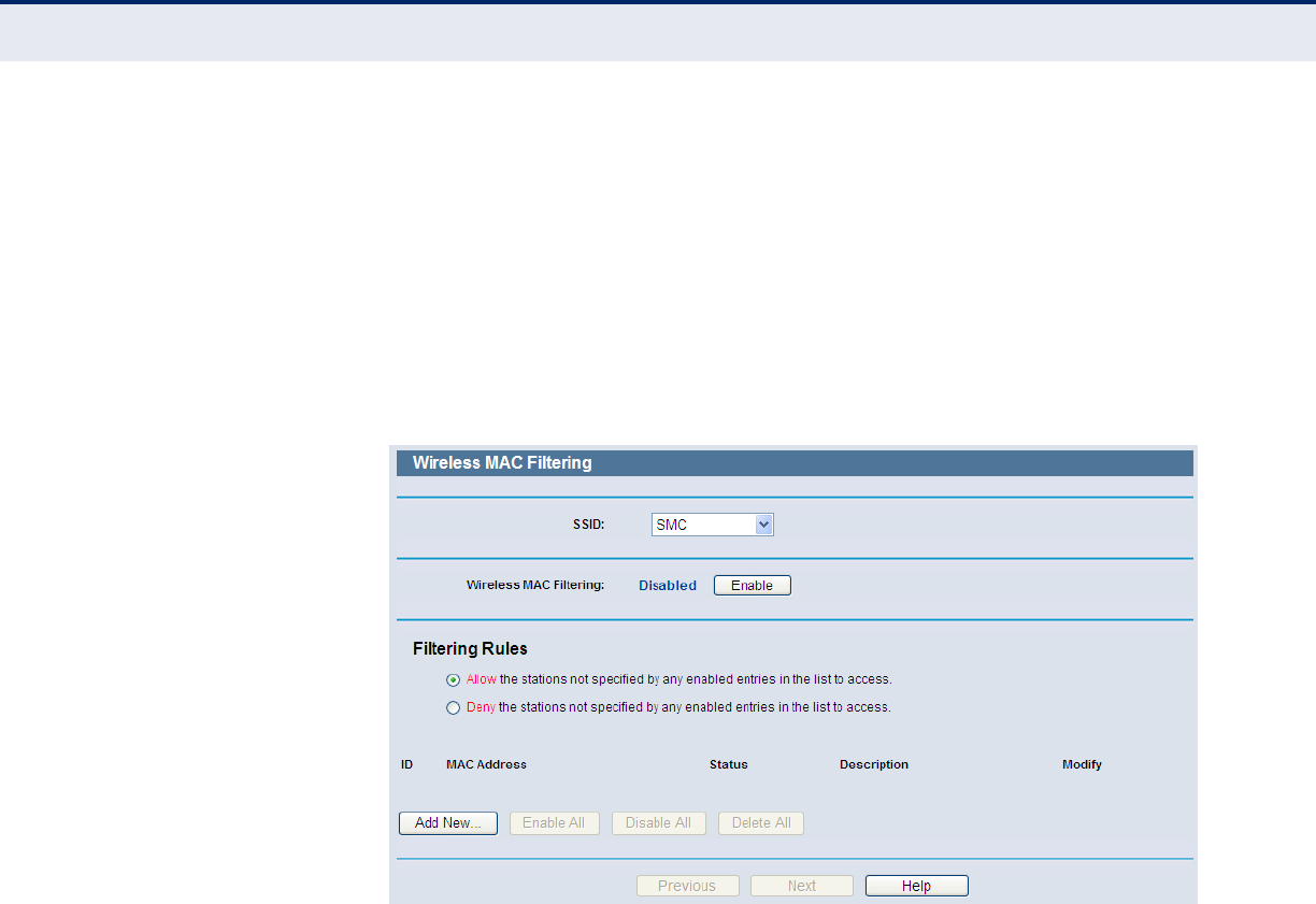
For example: If you want wireless station A (MAC address 00-0A-EB-00-
07-8A) and wireless station B (MAC address 00-0A-EB-00-23-11) to be
able to access the Router, but not all the other wireless stations, you can
configure the Wireless MAC Address Filtering list as follows:
1. Click the Enable button to enable this function.
2. Select the radio button: Deny the stations not specified by any enabled
entries in the list to access for Filtering Rules.
C
HAPTER
4
| Configuring the Router
Wireless
– 65 –
3. Delete all or disable all entries if there are any entries already.
4. Click the Add New button.
a. Enter the MAC address 00-0A-EB-00-07-8A /00-0A-EB-00-23-11 in
the MAC Address field.
b. Enter wireless station A/B in the Description field.
c. Select Enabled in the Status pull-down list.
d. Click the Save Button.
e. Click the Back button.
The filtering rules that are configured should look similar to the following
list:
Figure 55: Filtering Rules
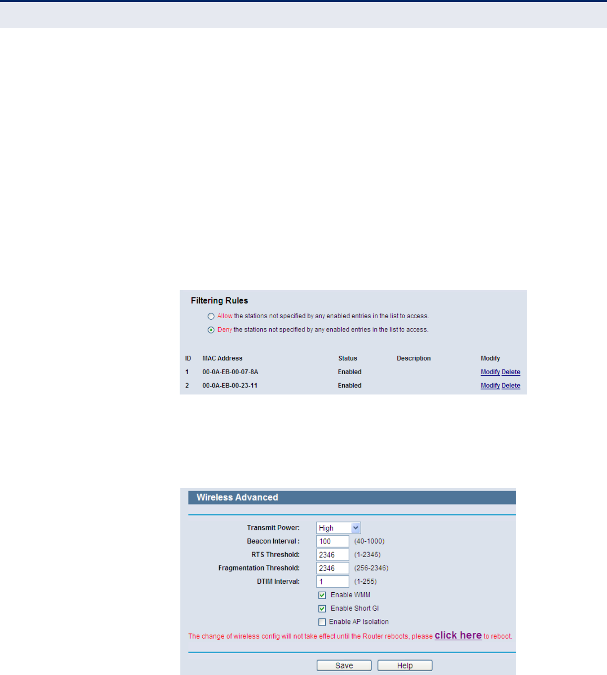
WIRELESS ADVANCED Choose Wireless -> Wireless Advanced from the menu; you can then
configure the advanced settings of your wireless network.
Figure 56: Wireless Advanced

C
HAPTER
4
| Configuring the Router
Wireless
– 66 –
◆Transmit Power - Here you can specify the transmit power of the
Router. You can select High, Middle, or Low. High is the default setting
and is recommended.
◆Beacon Interval - Enter a value between 20-1000 milliseconds for the
Beacon Interval. The beacons are packets sent by the router to
synchronize a wireless network. The Beacon Interval value determines
the time interval of beacons. The default value is 100.
◆RTS Threshold - Specifies the RTS (Request to Send) Threshold. If a
packet is larger than the specified RTS Threshold size, the router will
send RTS frames to a particular receiving station and negotiate the
sending of a data frame. The default value is 2346.
◆Fragmentation Threshold - This value determines the maximum size
before packets are fragmented. Setting the Fragmentation Threshold
too low may result in poor network performance since excessive
packets may be sent. The default setting is 2346 and is recommended.
◆DTIM Interval - This value determines the interval of the Delivery
Traffic Indication Message (DTIM). A DTIM field is a countdown field
informing clients of the next window for listening to broadcast and
multicast messages. When the Router has buffered broadcast or
multicast messages for associated clients, it sends the next DTIM with a
DTIM Interval value. You can specify the value between 1-255 Beacon
Intervals. The default value is 1, which indicates the DTIM Interval is
the same as Beacon Interval.
◆Enable WMM - The WMM function guarantees that packets with high-
priority messages are transmitted before other packets. It is strongly
recommended to enable this feature.
◆Enable Short GI - This function is recommended, since it increases
the data capacity by reducing the guard interval time.
◆Enabled AP Isolation - This function can isolate wireless stations on
your network from each other. Wireless devices will be able to
communicate with the Router, but not with each other. To use this
function, check this box. AP Isolation is disabled by default.
N
OTE
:
If you are not familiar with the settings on this page, it is strongly
recommended to keep the default values; otherwise it may result in lower
wireless network performance.
C
HAPTER
4
| Configuring the Router
Wireless
– 67 –
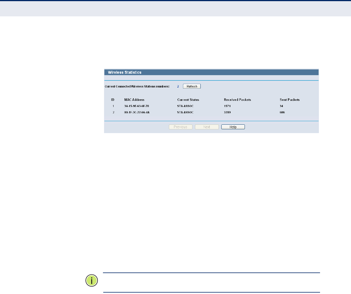
WIRELESS STATISTICS Select Wireless -> Wireless Statistics from the menu; you can see the
MAC Address, Current Status, Received Packets, and Sent Packets for each
connected wireless station.
Figure 57: Wireless Statistics
◆MAC Address - The connected wireless station's MAC address.
◆Current Status - The connected wireless station's running status, one
of STA-AUTH / STA-ASSOC / STA-JOINED / WPA / WPA-PSK / WPA2 /
WPA2-PSK / AP-UP / AP-DOWN / Disconnected.
◆Received Packets - Packets received by the station.
◆Sent Packets - Packets sent by the station.
You cannot change any of the values on this page. To update this page and
to show the current connected wireless stations, click on the Refresh
button.
If the numbers of connected wireless stations go beyond one page, click
the Next button to go to the next page, and click the Previous button to
return the previous page.
N
OTE
:
This page will be refreshed automatically every 5 seconds.
WPS This section shows how to quickly add a new wireless device to an existing
network using WPS (Wi-Fi Protected Setup).
1. Select WPS from the menu. You will see the next screen, as shown in
Figure .
C
HAPTER
4
| Configuring the Router
Wireless
– 68 –
Figure 58: WPS (Wi-Fi Protected Setup)
■WPS Status - Enable or disable the WPS function here.
■Current PIN - The current value of the Router's PIN is displayed
here. The default PIN of the Router can be found in the label or User
Guide.
■Restore PIN - Restore the PIN of the Router to its default.
■Gen New PIN - Click this button, and then you can get a new
random value for the Router's PIN. You can ensure the network
security by generating a new PIN.
■Add device - You can add a new device to the existing network
manually by clicking this button.
TO ADD A NEW DEVICE:
If the wireless adapter supports Wi-Fi Protected Setup (WPS), you can
establish a wireless connection between wireless adapter and Router using
either Push Button Configuration (PBC) method or PIN method.
N
OTE
:
To make a successful connection using WPS, you should also
perform the corresponding WPS configuration on the new device.
For the configuration of a new device, this example uses an SMC Wireless
Adapter.
BY PBC
If the wireless adapter supports Wi-Fi Protected Setup and the Push Button
Configuration (PBC) method, you can add it to the network by PBC with the
following two methods.
Method One:
1. Press the WPS button on the front panel of the Router.
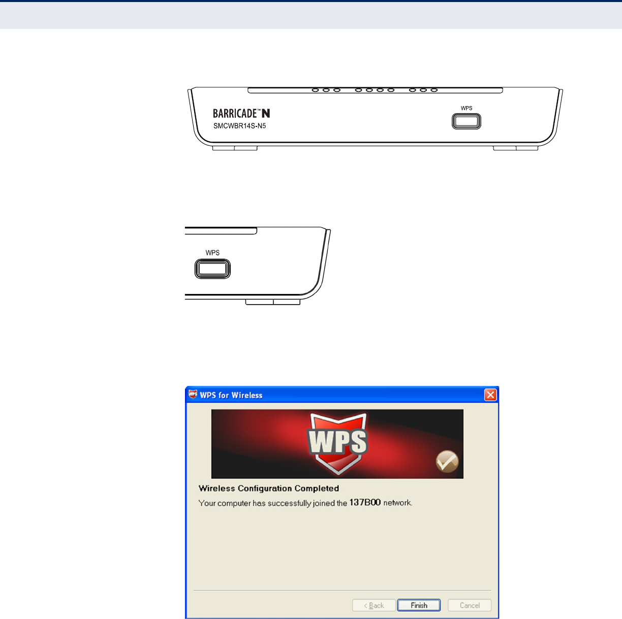
C
HAPTER
4
| Configuring the Router
Wireless
– 69 –
Figure 59: Front Panel
2. Press and hold the WPS button of the wireless client for 2 or 3 seconds.
Figure 60: WPS Button
3. Wait until the next screen appears. Click Finish to complete the WPS
configuration.
Figure 61: The WPS Configuration Screen of Wireless Adapter
Method Two:
1. Press the WPS button on the front panel of the Router.
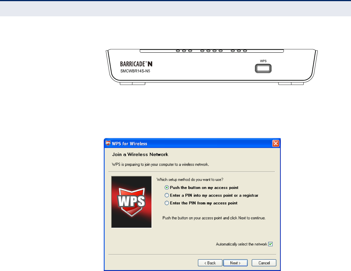
C
HAPTER
4
| Configuring the Router
Wireless
– 70 –
Figure 62: Front Panel
2. For the configuration of the wireless adapter, select “Push the button
on my access point” in the WPS configuration, as below, and click
Next.
Figure 63: The WPS Configuration Screen of Wireless Adapter
3. Wait until the next screen appears. Click Finish to complete the WPS
configuration.
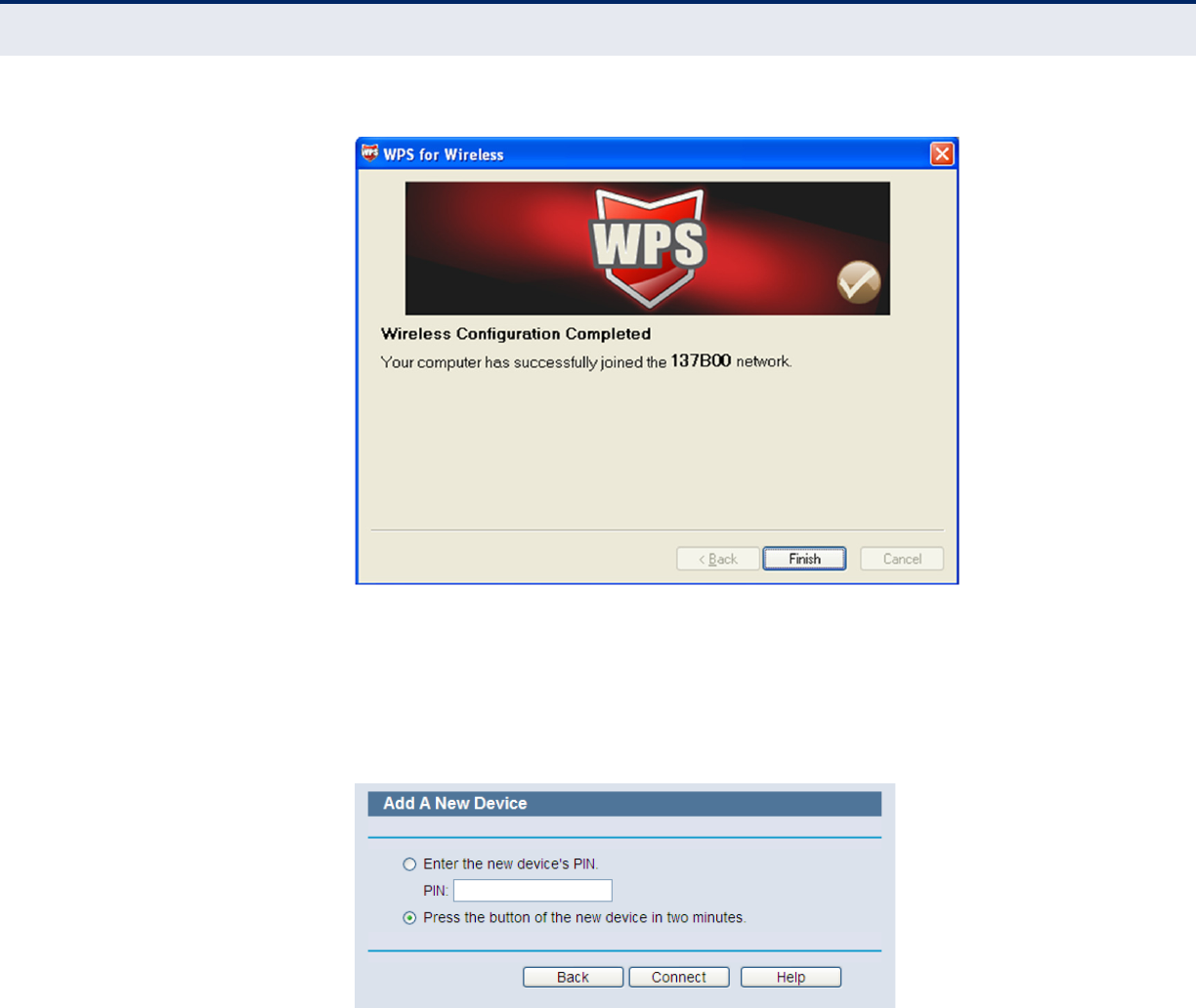
C
HAPTER
4
| Configuring the Router
Wireless
– 71 –
Figure 64: The WPS Configuration Screen of Wireless Adapter
Method Three:
1. Keep the default WPS Status as Enabled and click the “Add device”
button in Figure 58, then the following screen will appear.
Figure 65: Add A New Device
2. Select “Press the button of the new device in two minutes” and click
Connect.
3. For the configuration of the wireless adapter, select “Push the button on
my access point” in the WPS configuration utility, as below, and click
Next.
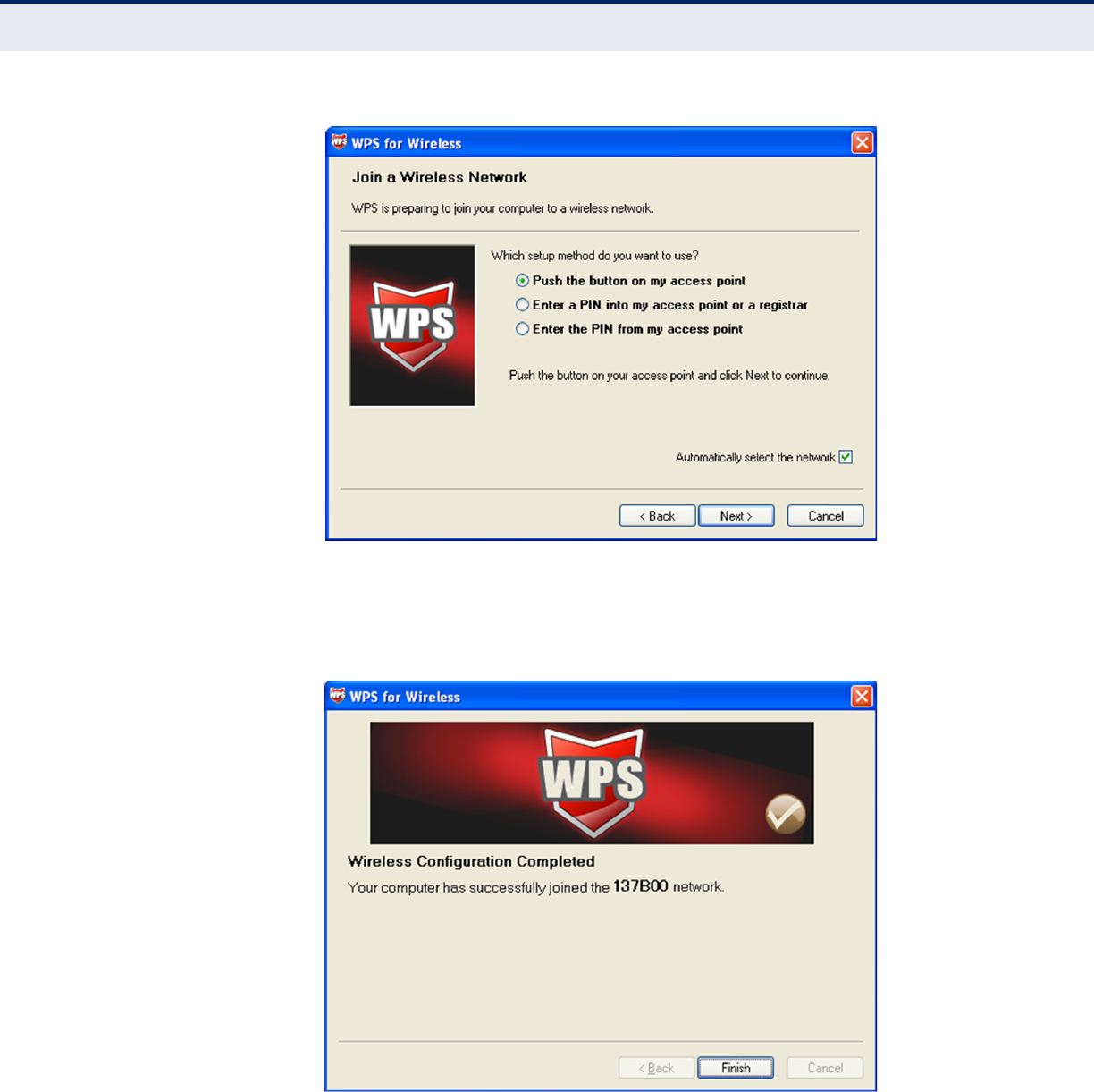
C
HAPTER
4
| Configuring the Router
Wireless
– 72 –
Figure 66: The WPS Configuration Screen of Wireless Adapter
4. Wait until the next screen appears. Click Finish to complete the WPS
configuration.
Figure 67: The WPS Configuration Screen of Wireless Adapter
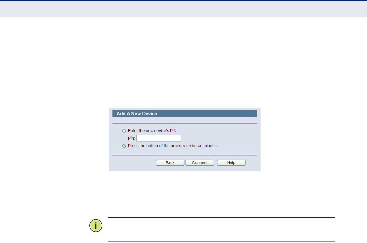
C
HAPTER
4
| Configuring the Router
Wireless
– 73 –
BY PIN
If the new device supports Wi-Fi Protected Setup and the PIN method, you
can add it to the network by PIN with the following two methods.
Method One: Enter the PIN into my Router.
1. Keep the default WPS Status as Enabled and click the “Add device”
button in Figure 58, then the following screen will appear.
Figure 68: Add Device
2. Select “Enter the new device's PIN” and enter the PIN code of the
wireless adapter in the field after PIN, as shown in the figure above.
Then click Connect.
N
OTE
:
The PIN code of the adapter is always displayed on the WPS
configuration screen.
3. For the configuration of the wireless adapter, selected “Enter a PIN into
my access point or a registrar” in the WPS configuration, as below, and
click Next.
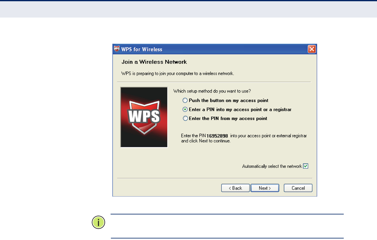
C
HAPTER
4
| Configuring the Router
Wireless
– 74 –
Figure 69: The WPS Configuration Screen of Wireless Adapter
N
OTE
:
In this example, the default PIN code of the adapter is 16952898, as
shown in the above figure.
Method Two: Enter the PIN from my Router.
1. Read the Current PIN code of the Router in Figure 58 (each Router has
its unique PIN code. This example has the Router PIN code 12345670).
2. For the configuration of the wireless adapter, select “Enter a PIN from
my access point” in the WPS configuration utility, as below, and enter
the PIN code of the Router into the field after “Access Point PIN”. Then
click Next.
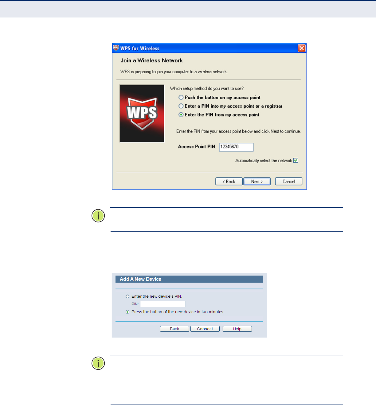
C
HAPTER
4
| Configuring the Router
Wireless
– 75 –
Figure 70: The WPS Configuration Screen of Wireless Adapter
N
OTE
:
The default PIN code of the Router can be found on its label, or in
the WPS configuration screen, as shown in Figure 58.
You will see the following screen when the new device is successfully
connected to the network.
Figure 71: Add a New Device
N
OTE
:
The WPS LED on the Router will turn on green for five minutes when
a device has been successfully added to the network.
N
OTE
:
The WPS function cannot be configured if the wireless function of the
Router is disabled. Make sure the wireless function is enabled before
configuring WPS.
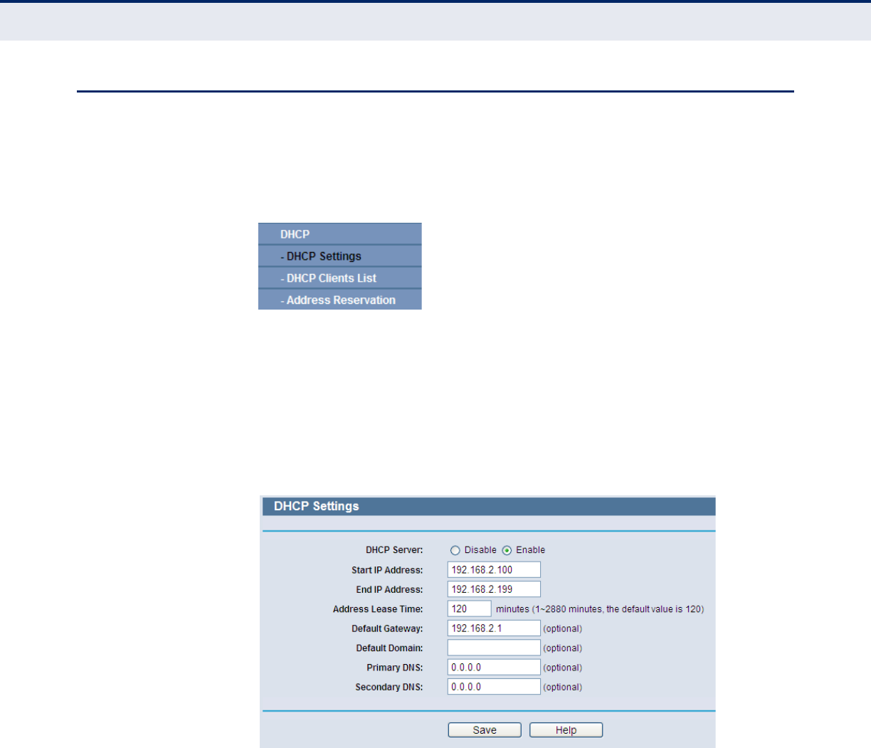
C
HAPTER
4
| Configuring the Router
DHCP
– 76 –
DHCP
There are three submenus under the DHCP menu (shown in Figure 72):
DHCP Settings, DHCP Clients List, and Address Reservation. Click any of
them, and you will be able to configure the corresponding function.
Figure 72: The DHCP Menu
DHCP SETTINGS Select DHCP -> DHCP Settings from the menu. You can configure the
DHCP Server on the page, as shown in Figure 73. The Router is set up by
default as a DHCP (Dynamic Host Configuration Protocol) server, which
provides the TCP/IP configuration for all the PCs that are connected to the
Router on the LAN.
Figure 73: DHCP Settings
◆DHCP Server - Enable or Disable the DHCP server. If you disable the
Server, you must have another DHCP server in your network or you
must configure computers manually.
◆Start IP Address - Specify an IP address for the DHCP Server to start
with when assigning IP addresses. 192.168.2.100 is the default start
address.
◆End IP Address - Specify an IP address for the DHCP Server to end
with when assigning IP addresses. 192.168.2.199 is the default end
address.
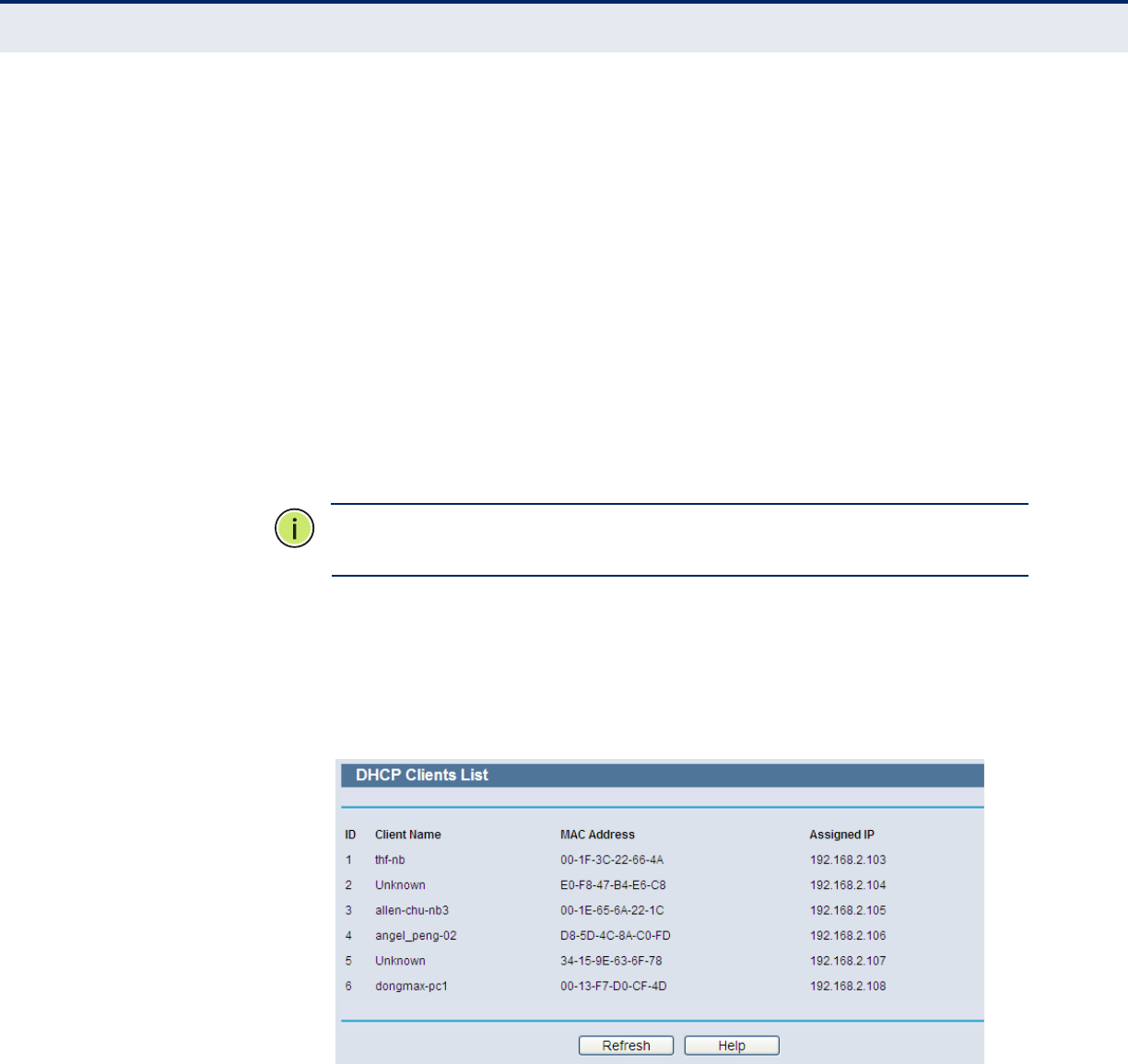
C
HAPTER
4
| Configuring the Router
DHCP
– 77 –
◆Address Lease Time - The amount of time a network user will be
allowed connection to the Router with their current dynamic IP Address.
Enter the amount of time in minutes and the user will be “leased” this
dynamic IP Address. After the time is up, the user will be automatically
assigned a new dynamic IP address. The range of the time is 1 ~ 2880
minutes. The default value is 120 minutes.
◆Default Gateway - (Optional.) Suggest to input the IP address of the
LAN port of the Router, default value is 192.168.2.1
◆Default Domain - (Optional.) Input the domain name of your network.
◆Primary DNS - (Optional.) Input the DNS IP address provided by your
ISP. Or consult your ISP.
◆Secondary DNS - (Optional.) Input the IP address of another DNS
server if your ISP provides two DNS servers.
N
OTE
:
To use the DHCP server function of the Router, you must configure
all computers on the LAN as "Obtain an IP Address automatically" mode.
DHCP CLIENTS LIST Select DHCP -> DHCP Clients List from the menu; you can view the
information about the clients attached to the Router in the next screen
(shown in Figure 74).
Figure 74: DHCP Clients List
◆ID - The index of the DHCP Client.
◆Client Name - The name of the DHCP client.
◆MAC Address - The MAC address of the DHCP client.
◆Assigned IP - The IP address that the Router has allocated to the
DHCP client.
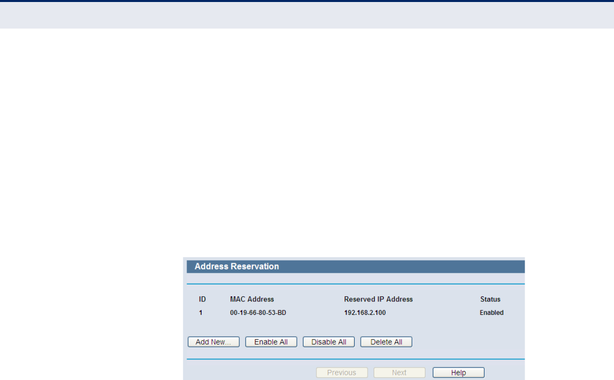
C
HAPTER
4
| Configuring the Router
DHCP
– 78 –
◆Lease Time - The time of the DHCP client leased. After the dynamic IP
address has expired, a new dynamic IP address will be automatically
assigned to the user.
You cannot change any of the values on this page. To update this page and
to show the current attached devices, click the Refresh button.
ADDRESS
RESERVATION
Select DHCP -> Address Reservation from the menu; you can view and
add reserved addresses for clients from the next screen (shown in
Figure 75). When you specify a reserved IP address for a PC on the LAN,
that PC will always receive the same IP address each time when it accesses
the DHCP server. Reserved IP addresses should be assigned to servers that
require permanent IP settings.
Figure 75: Address Reservation
◆MAC Address - The MAC address of the PC for which you want to
reserve an IP address.
◆Assigned IP Address - The reserved IP address for the PC.
◆Status - The status of this entry either Enabled or Disabled.
To Reserve IP addresses:
1. Click the “Add New” button (as shown in Figure 76).
2. Enter the MAC address (in XX-XX-XX-XX-XX-XX format.) and IP address
in dotted-decimal notation of the computer you wish to add.
3. Click the Save button when finished.
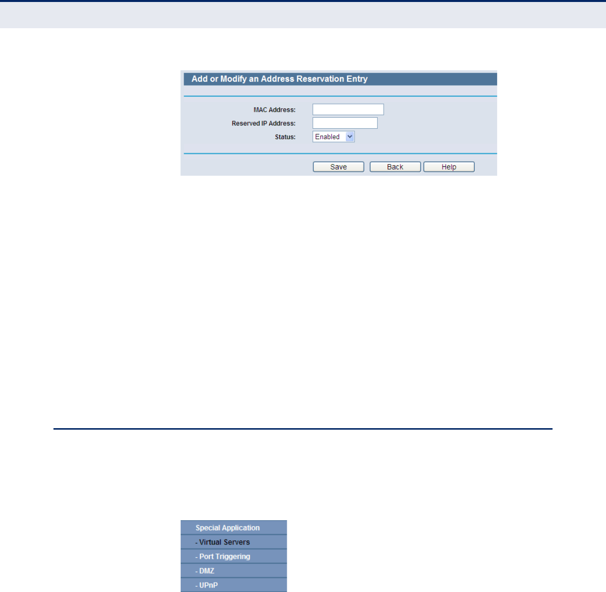
C
HAPTER
4
| Configuring the Router
Special Application
– 79 –
Figure 76: Add or Modify an Address Reservation Entry
To modify or delete an existing entry:
1. Click Modify in the entry you want to modify. If you want to delete the
entry, click the Delete.
2. Modify the information.
3. Click the Save button.
4. Click the Enable/Disable All button to enable/disable all entries.
5. Click the Delete All button to delete all entries.
6. Click the Next button to go to the next page and click the Previous
button to return the previous page.
SPECIAL APPLICATION
There are four submenus under the Special Application menu (shown in
Figure 77): Virtual Servers, Port Triggering, DMZ, and UPnP. Click any
of them and you will be able to configure the corresponding function.
Figure 77: The Special Application Menu
VIRTUAL SERVERS Select Special Application->Virtual Servers from the menu; you can
view and add virtual servers in the next screen (as shown in Figure 78).
Virtual servers can be used for setting up public services on your LAN, such
as DNS, Email and FTP. A virtual server is defined as a service port, and all
requests from the Internet to this service port will be redirected to the
computer specified by the server IP. Any PC that was used for a virtual
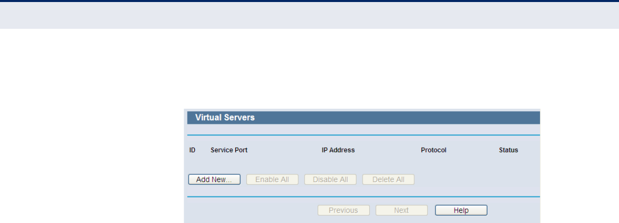
C
HAPTER
4
| Configuring the Router
Special Application
– 80 –
server must have a static or reserved IP Address because its IP Address
may be changed when using the DHCP function.
Figure 78: Virtual Servers
◆Service Port - The number of an external port. You can type a service
port or a range of service ports (in XXX – YYY format, XXX is the start
port number, YYY is the end port number).
◆IP Address - The IP Address of the PC providing the service
application.
◆Protocol - The protocol used for this application, either TCP, UDP, or All
(all protocols supported by the Router).
◆Status - The status of this entry either Enabled or Disabled.
To setup a virtual server entry:
1. Click the Add New… button. (Figure 79)
2. Select the service you want to use from the Common Service Port
list. If the Common Service Port list does not have the service that
you want to use, type the number of the service port or service port
range in the Service Port box.
3. Type the IP Address of the computer in the IP Address box.
4. Select the protocol used for this application, either TCP, UDP, or All.
5. Select the Enable check box to enable the virtual server.
6. Click the Save button.
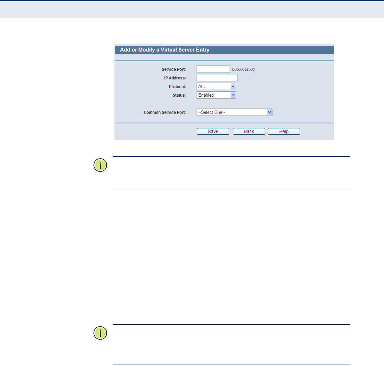
C
HAPTER
4
| Configuring the Router
Special Application
– 81 –
Figure 79: Add or Modify a Virtual Server Entry
N
OTE
:
If your computer or server has more than one type of available
service, please select another service, and enter the same IP Address for
that computer or server.
To modify or delete an existing entry:
1. Click Modify for the entry you want to modify. If you want to delete the
entry, click Delete.
2. Modify the information.
3. Click the Save button.
4. Click the Enable/Disable All button to enable/disable all entries.
5. Click the Delete All button to delete all entries.
6. Click the Next button to go to the next page and click the Previous
button to return the previous page.
N
OTE
:
If you set the service port of the virtual server as 80, you must set
the Web management port on “Security –> Remote Management” page
to be any other value except 80, such as 8080. Otherwise there will be a
conflict, which will disable the virtual server.
PORT TRIGGERING Select Special Application -> Port Triggering from the menu; you can
view and add port triggering in the next screen (shown in Figure 80). Some
applications require multiple connections, like Internet games, video
conferencing, Internet calling and so on. These applications cannot work
with a pure NAT Router. Port Triggering is used for some of these
applications that can work with a NAT Router.
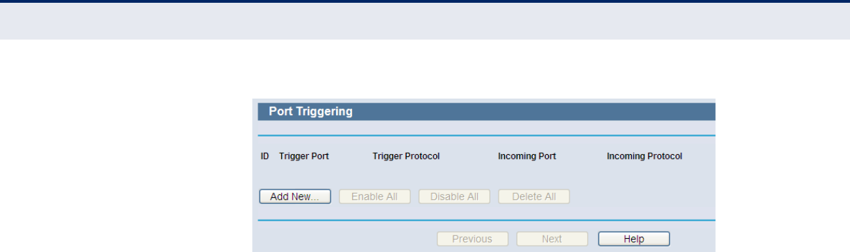
C
HAPTER
4
| Configuring the Router
Special Application
– 82 –
Figure 80: Port Triggering
Once the Router is configured, the operation is as follows:
1. A local host makes an outgoing connection using a destination port
number defined in the Trigger Port field.
2. The Router records this connection, opens the incoming port or ports
associated with this entry in the Port Triggering table, and associates
them with the local host.
3. When necessary the external host will be able to connect to the local
host using one of the ports defined in the Incoming Ports field.
◆Trigger Port - The port for outgoing traffic. An outgoing connection
using this port will "Trigger" this rule.
◆Trigger Protocol - The protocol used for Trigger Ports, either TCP,
UDP, or All (all protocols supported by the Router).
◆Incoming Ports Range - The port or port range used by the remote
system when it responds to the outgoing request. A response using one
of these ports will be forwarded to the PC that triggered this rule. You
can input at most 5 groups of ports (or port section). Every group of
ports must be set apart with ",". For example, 2000-2038, 2050-2051,
2085, 3010-3030.
◆Incoming Protocol - The protocol used for Incoming Ports Range,
either TCP or UDP, or ALL (all protocols supported by the Router).
◆Status - The status of this entry either Enabled or Disabled.
To add a new rule, follow the steps below.
1. Click the “Add New” button, the next screen will pop-up as shown in
Figure 81.
2. Select a common application from the Common Applications drop-down
list, then the Trigger Port field and the Incoming Ports field will be
automatically filled. If the Common Applications do not have the
application you need, enter the Trigger Port and the Incoming Ports
manually.
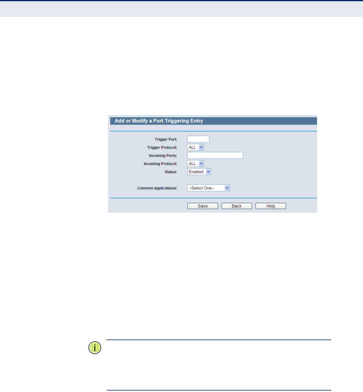
C
HAPTER
4
| Configuring the Router
Special Application
– 83 –
3. Select the protocol used for Trigger Port from the Trigger Protocol drop-
down list, either TCP, UDP, or All.
4. Select the protocol used for Incoming Ports from the Incoming Protocol
drop-down list, either TCP or UDP, or All.
5. Select Enable in Status field.
6. Click the Save button to save the new rule.
Figure 81: Add or Modify a Triggering Entry
To modify or delete an existing entry:
1. Click Modify in the entry you want to modify. If you want to delete the
entry, click Delete.
2. Modify the information.
3. Click the Save button.
4. Click the Enable All button to make all entries enabled
5. Click the Disabled All button to make all entries disabled.
6. Click the Delete All button to delete all entries
N
OTE
:
When the trigger connection is released, the according opening ports
will be closed.
N
OTE
:
Each rule allowed to be used only by one host on LAN synchronously.
The trigger connection of other hosts on LAN will be refused.
N
OTE
:
Incoming Port Ranges cannot overlap each other.
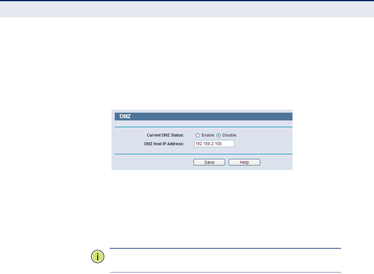
C
HAPTER
4
| Configuring the Router
Special Application
– 84 –
DMZ Select Special Application -> DMZ from the menu; you can view and
configure the DMZ host in the screen (shown in Figure 82).The DMZ host
feature allows one local host to be exposed to the Internet for a special-
purpose service such as Internet gaming or videoconferencing. DMZ host
forwards all the ports at the same time. Any PC whose port is being
forwarded must have its DHCP client function disabled and should have a
new static IP Address assigned to it because its IP Address may be
changed when using the DHCP function.
Figure 82: DMZ
To assign a computer or server to be a DMZ server:
1. Click the Enable radio button
2. Enter the local host IP Address in the DMZ Host IP Address field
3. Click the Save button.
N
OTE
:
After you set the DMZ host, the firewall related to the host will not
work.
UPNPSelect Special Application -> UPnP from the menu; you can view the
information about UPnP (Universal Plug and Play) in the screen (shown in
Figure 83). The UPnP feature allows devices, such as Internet computers,
to access the local host resources or devices as needed. UPnP devices can
be automatically discovered by the UPnP service application on the LAN.
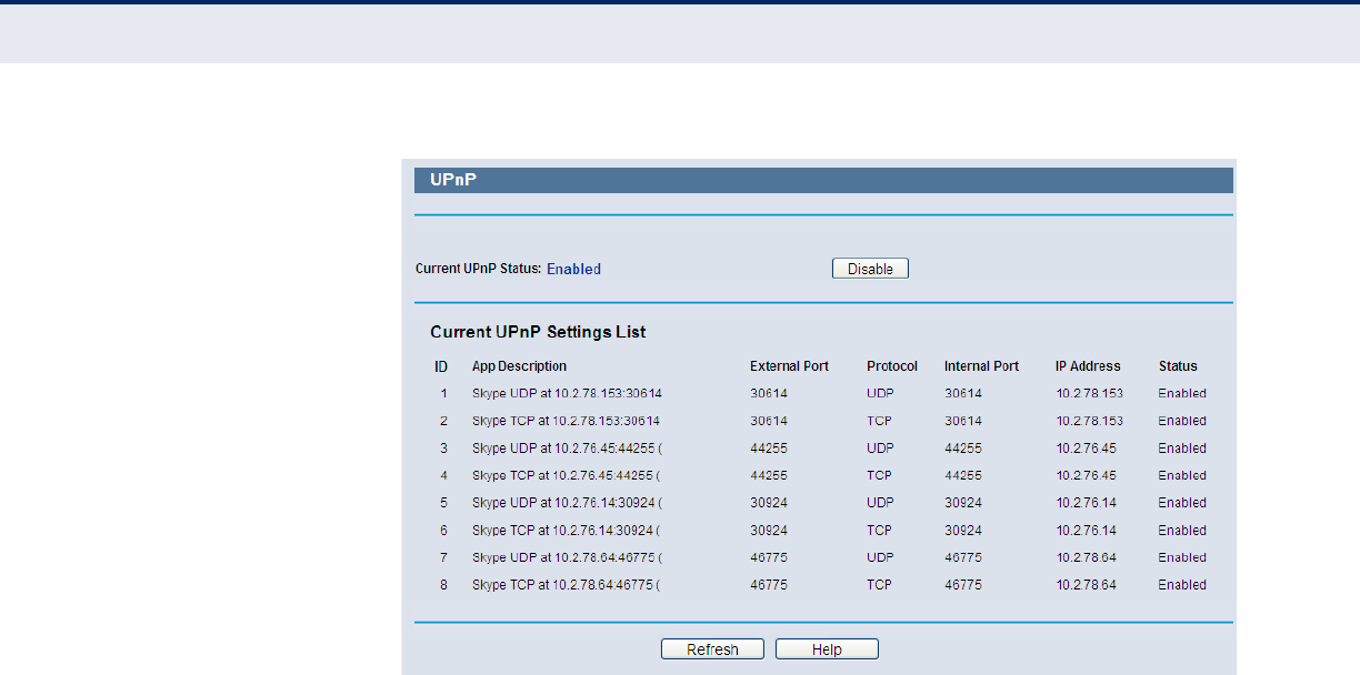
C
HAPTER
4
| Configuring the Router
Special Application
– 85 –
Figure 83: UPnP
◆Current UPnP Status - UPnP can be enabled or disabled by clicking
the Enable or Disable button. As allowing this may present a risk to
security, this feature is enabled by default.
◆Current UPnP Settings List - This table displays the current UPnP
information.
■App Description - The description provided by the application in
the UPnP request
■External Port - External port, which the router opened for the
application.
■Protocol - Shows which type of protocol is opened.
■Internal Port - Internal port, which the router opened for local
host.
■IP Address - The UPnP device that is currently accessing the
router.
■Status - The port’s status displayed here. “Enabled” means that
port is still active. Otherwise, the port is inactive.
Click Refresh to update the Current UPnP Settings List.
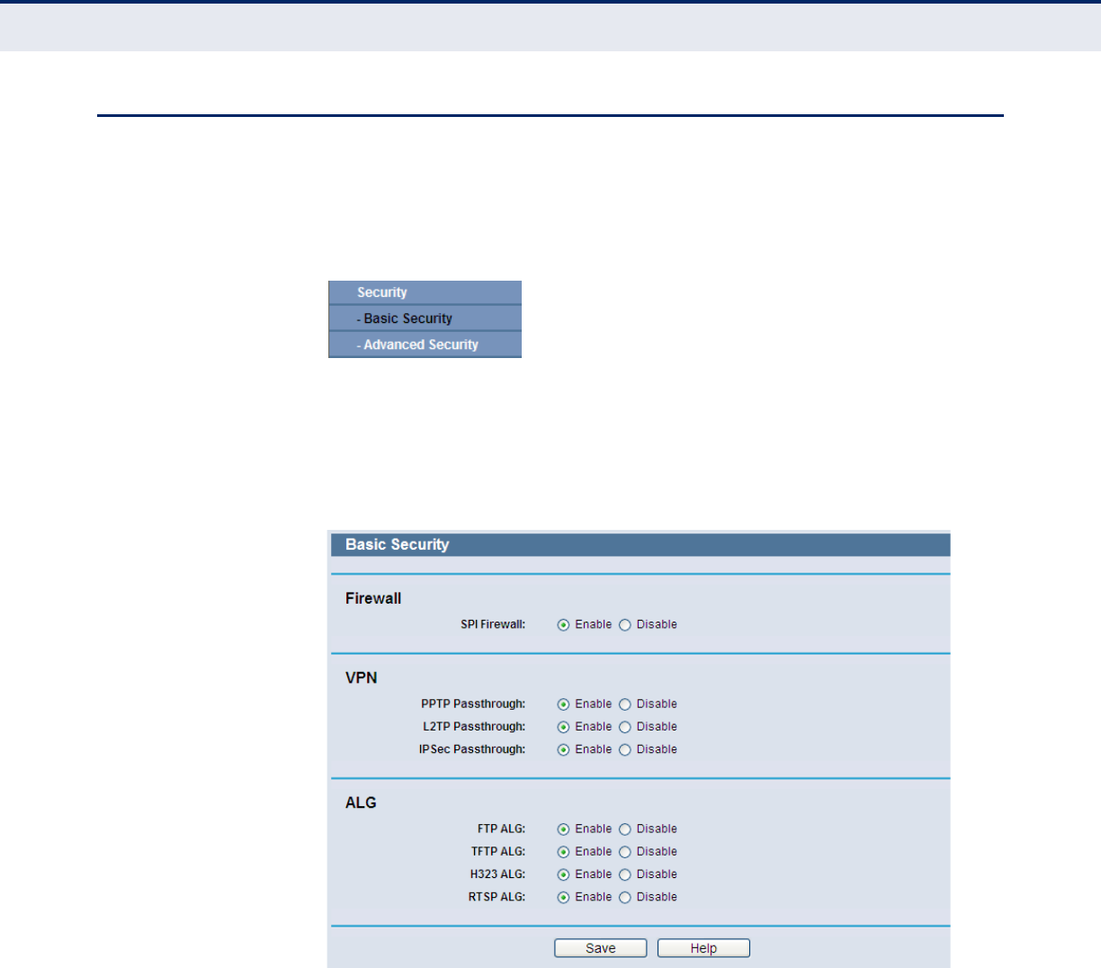
C
HAPTER
4
| Configuring the Router
Security
– 86 –
SECURITY
There are two submenus under the Security menu as shown in Figure 84:
Basic Security and Advanced Security. Click any of them, and you will be
able to configure the corresponding function.
Figure 84: The Security menu
BASIC SECURITY Select Security -> Basic Security from the menu; you can configure the
basic security in the screen as shown in Figure 85.
Figure 85: Basic Security
◆Firewall - A firewall protects your network from the outside world.
Here you can enable or disable the Router’s firewall.
■SPI Firewall - SPI (Stateful Packet Inspection, also known as
dynamic packet filtering) helps to prevent cyber attacks by tracking
states per session. It validates that the traffic passing through the
session conforms to the protocol. SPI Firewall is enabled by factory
default. If you want all the computers on the LAN exposed to the
outside world, you can disable it.

C
HAPTER
4
| Configuring the Router
Security
– 87 –
◆VPN - VPN Passthrough must be enabled if you want to allow VPN
tunnels using IPSec, PPTP, or L2TP protocols to pass through the
Router’s firewall.
■PPTP Passthrough - Point-to-Point Tunneling Protocol (PPTP)
allows the Point-to-Point Protocol (PPP) to be tunneled through an
IP network. To allow PPTP tunnels to pass through the Router, keep
the default, Enabled.
■L2TP Passthrough - Layer 2 Tunneling Protocol (L2TP) is the
method used to enable Point-to-Point sessions via the Internet on
the Layer 2 level. To allow L2TP tunnels to pass through the Router,
keep the default, Enabled.
■IPSec Passthrough - Internet Protocol Security (IPSec) is a suite
of protocols for ensuring private, secure communications over
Internet Protocol (IP) networks, through the use of cryptographic
security services. To allow IPSec tunnels to pass through the Router,
keep the default, Enabled.
◆ALG - It is recommended to enable Application Layer Gateway (ALG)
because ALG allows customized Network Address Translation (NAT)
traversal filters to be plugged into the gateway to support address and
port translation for certain application layer "control/data" protocols
such as FTP, TFTP, H323 etc.
■FTP ALG - To allow FTP clients and servers to transfer data across
NAT, keep the default Enable.
■TFTP ALG - To allow TFTP clients and servers to transfer data
across NAT, keep the default Enable.
■H323 ALG - To allow Microsoft NetMeeting clients to communicate
across NAT, keep the default Enable.
Click the Save button to save your settings.
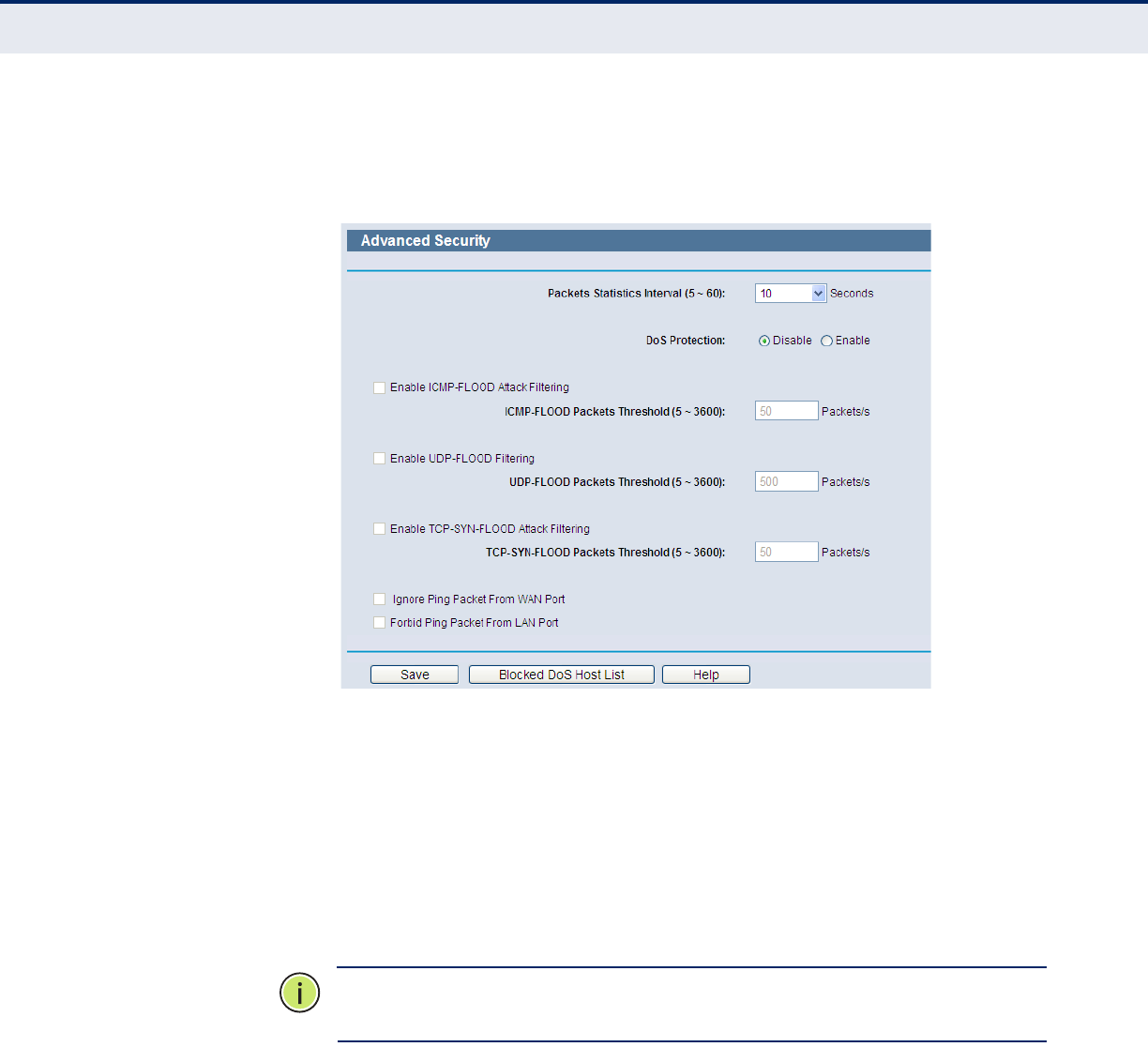
C
HAPTER
4
| Configuring the Router
Security
– 88 –
ADVANCED SECURITY Select Security -> Advanced Security from the menu; you can protect
the Router from being attacked by TCP-SYN Flood, UDP Flood and ICMP-
Flood in the screen, as shown in Figure 86.
Figure 86: Advanced Security
◆Packets Statistics Interval (5~60) - The default value is 10. Select
a value between 5 and 60 seconds from the drop-down list. The Packets
Statistics Interval value indicates the time section of the packets
statistics. The result of the statistics is used for analysis by SYN Flood,
UDP Flood and ICMP-Flood.
◆DoS Protection - Denial of Service protection. Check the Enable or
Disable button to enable or disable the DoS protection function. Only
when it is enabled, will the flood filters be enabled.
N
OTE
:
Dos Protection will take effect only when the Traffic Statistics in
“System Tool > Traffic Statistics” is enabled.
◆Enable ICMP-FLOOD Attack Filtering - Enable or Disable the ICMP-
FLOOD Attack Filtering.
◆ICMP-FLOOD Packets Threshold (5~3600) - The default value is
50. Enter a value between 5 ~ 3600. When the current ICMP-FLOOD
Packets number is beyond the set value, the Router will startup the
blocking function immediately.
◆Enable UDP-FLOOD Filtering - Enable or Disable the UDP-FLOOD
Filtering.
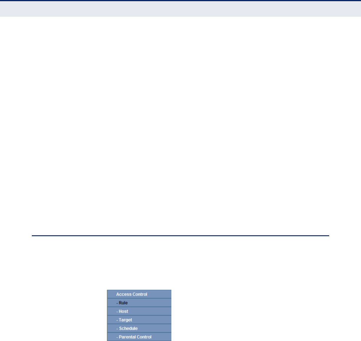
C
HAPTER
4
| Configuring the Router
Access Control
– 89 –
◆UDP-FLOOD Packets Threshold (5~3600) - The default value is
500. Enter a value between 5 ~ 3600. When the current UPD-FLOOD
Packets number is beyond the set value, the Router will startup the
blocking function immediately.
◆Enable TCP-SYN-FLOOD Attack Filtering - Enable or Disable the
TCP-SYN-FLOOD Attack Filtering.
◆TCP-SYN-FLOOD Packets Threshold (5~3600) - The default value
is 50. Enter a value between 5 ~ 3600. When the current TCP-SYN-
FLOOD Packets numbers is beyond the set value, the Router will startup
the blocking function immediately.
◆Ignore Ping Packet From WAN Port - Enable or Disable Ignore Ping
Packet From WAN Port. The default setting is disabled. If enabled, the
ping packet from the Internet cannot access the Router.
◆Forbid Ping Packet From LAN Port - Enable or Disable Forbid Ping
Packet From LAN Port. The default setting is disabled. If enabled, the
ping packet from LAN cannot access the Router. This function can be
used to defend against some viruses.
Click the Save button to save the settings.
Click the Blocked DoS Host List button to display the DoS host table by
blocking.
ACCESS CONTROL
There are five submenus under the Access Control menu as shown in
Figure 87: Rule, Host, Target, Schedule, and Parental Control. Click any of
them, and you will be able to configure the corresponding function.
Figure 87: Access Control
RULE Select Access Control->Rule from the menu; you can view and set
access control rules in the screen, as shown in Figure 88.
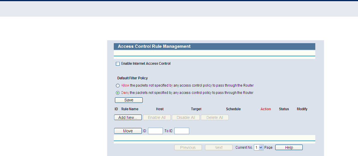
C
HAPTER
4
| Configuring the Router
Access Control
– 90 –
Figure 88: Access Control Rule Management
◆Enable Internet Access Control - Select the check box to enable the
Internet Access Control function, so the Default Filter Policy can take
effect.
◆Rule Name - Here displays the name of the rule and this name is
unique.
◆Host - Here displays the host selected in the corresponding rule.
◆Target - Here displays the target selected in the corresponding rule.
◆Schedule - Here displays the schedule selected in the corresponding
rule.
◆Action - Here displays the action the Router takes to deal with the
packets. It could be Allow or Deny. Allow means that the Router permits
the packets to go through the Router. Deny means that the Router
rejects the packets to go through the Router.
◆Status - This field displays the status of the rule. Enabled means the
rule will take effect, Disabled means the rule will not take effect.
◆Modify - Here you can edit or delete an existing rule.
To add a new rule, please follow the steps below.
1. Click the “Add New” button and the next screen will pop-up, as shown
in Figure 89.
2. Give a name (e.g. Rule_1) for the rule in the Rule Name field.
3. Select a host from the Host drop-down list or choose “Click Here To Add
New Host List”.
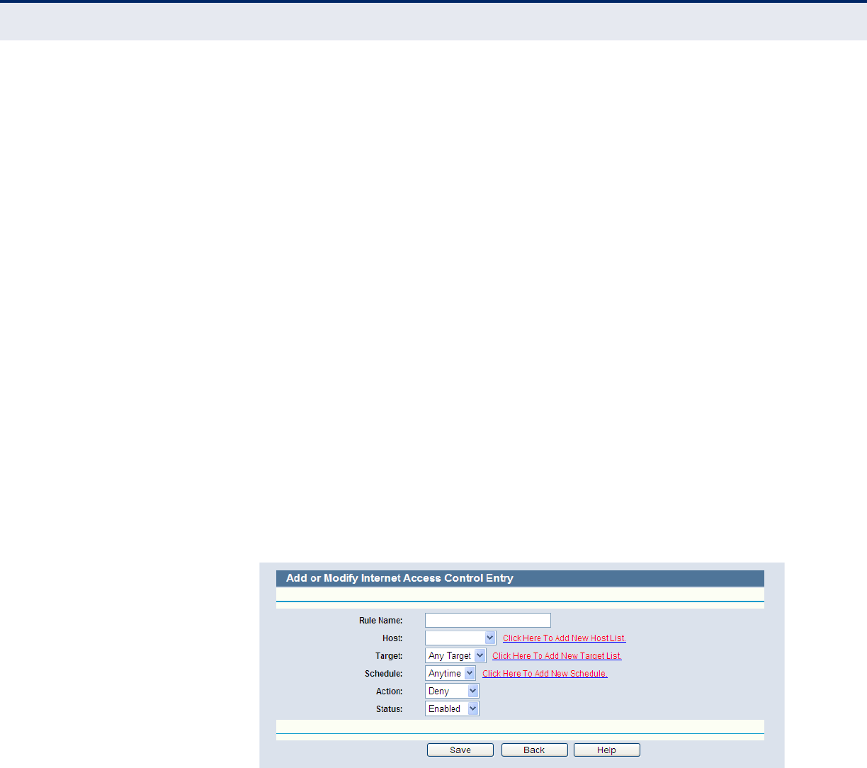
C
HAPTER
4
| Configuring the Router
Access Control
– 91 –
4. Select a target from the Target drop-sown list or choose “Click Here To
Add New Target List”.
5. Select a schedule from the Schedule drop-down list or choose “Click
Here To Add New Schedule”.
6. In the Action field, select Deny or Allow.
7. In the Status field, select Enabled or Disabled to enable or disable your
entry.
Click the Save button.
Click the Enable All button to enable all the rules in the list.
Click the Disable All button to disable all the rules in the list.
Click the Delete All button to delete all the entries in the table.
You can change the entry’s order as desired. Fore entries are before hind
entries. Enter the ID number in the first box you want to move and another
ID number in second box you want to move to, and then click the Move
button to change the entry’s order.
Click the Next button to go to the next page, or click the Previous button
return to the previous page.
Figure 89: Add or Modity Internet Access Control Entry
For example: If you desire to allow the host with MAC address 00-11-22-
33-44-AA to access www.google.com only from 18:00 to 20:00 on
Saturday and Sunday, and forbid other hosts in the LAN to access the
Internet, you should follow the settings below:
1. Click “Access Control->Host” in the left to enter the Host Settings page.
Add a new entry with the Host Description is Host_1 and MAC Address
is 00-11-22-33-44-AA.
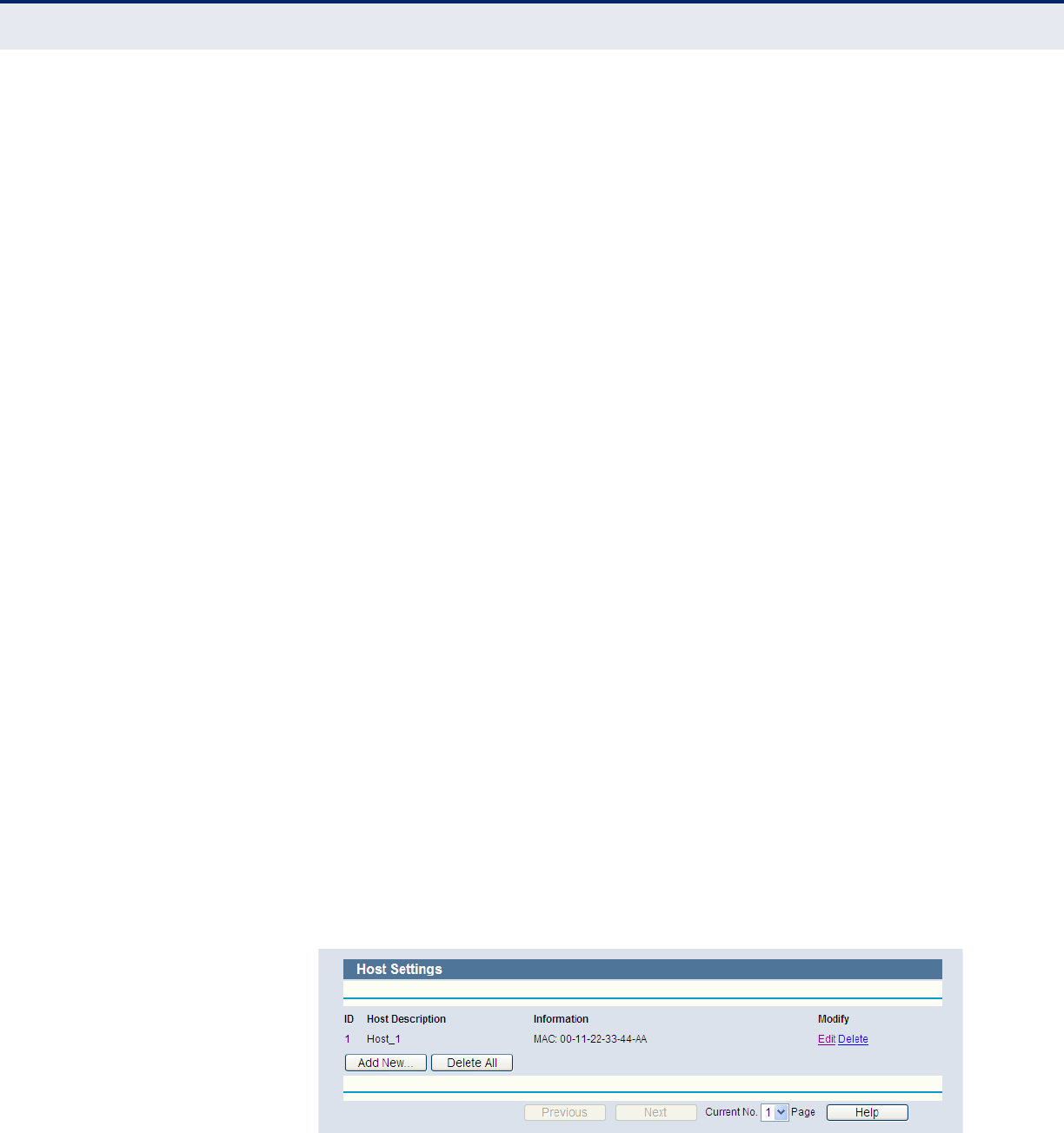
C
HAPTER
4
| Configuring the Router
Access Control
– 92 –
2. Click “Access Control->Target” in the left to enter the Target Settings
page. Add a new entry with the Target Description is Target_1 and
Domain Name is www.google.com.
3. Click “Access Control->Schedule” in the left to enter the Schedule
Settings page. Add a new entry with the Schedule Description is
Schedule_1, Day is Sat and Sun, Start Time is 1800 and Stop Time is
2000.
4. Click “Access Control->Rule” in the left to return to the Access Control
Rule Management page. Select “Enable Internet Access Control” and
choose "Deny the packets not specified by any access control policy to
pass through the Router".
5. Click the “Add New” button to add a new rule as follows:
■In Rule Name field, create a name for the rule. Note that this name
should be unique, for example Rule_1.
■In Host field, select Host_1.
■In Target field, select Target_1.
■In Schedule field, select Schedule_1.
■In Action field, select Allow.
■In Status field, select Enable.
■Click Save to complete the settings.
Then you will go back to the Access Control Rule Management page and
see the following list.
HOST Select Access Control->Host from the menu; you can view and set a
Host list in the screen, as shown in Figure 90. The host list is necessary for
the Access Control Rule.
Figure 90: Host Settings
◆Host Description - Displays the description of the host and this
description is unique.
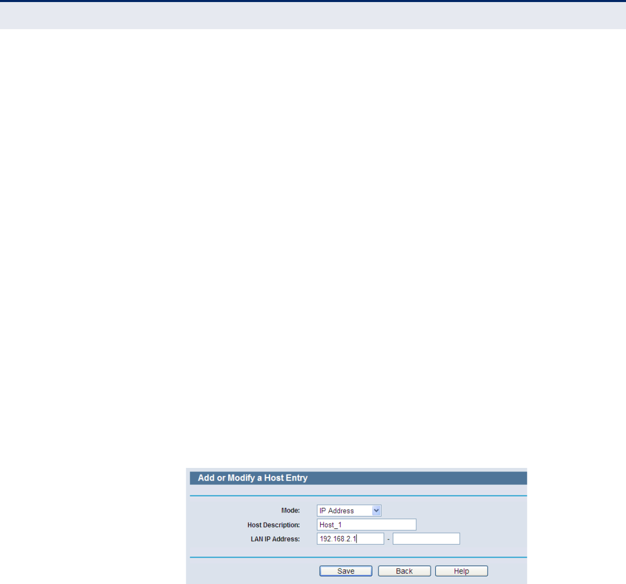
C
HAPTER
4
| Configuring the Router
Access Control
– 93 –
◆Information - Displays the information about the host. It can be IP or
MAC.
◆Modify - To modify or delete an existing entry.
To add a new entry, please follow the steps below.
1. Click the “Add New” button.
2. In the Mode field, select IP Address or MAC Address.
■If you select IP Address, the screen in Figure 91 is displayed.
●In the Host Description field, create a unique description for the
host (e.g. Host_1).
●In LAN IP Address field, enter the IP address.
■If you select MAC Address, the screen in Figure 92 is displayed.
●In Host Description field, create a unique description for the host
(e.g. Host_1).
●In MAC Address field, enter the MAC address.
3. Click the Save button to complete the settings.
Click the Delete All button to delete all the entries in the table.
Click the Next button to go to the next page, or click the Previous button
return to the previous page.
Figure 91: Add or Modify an IP Host Entry
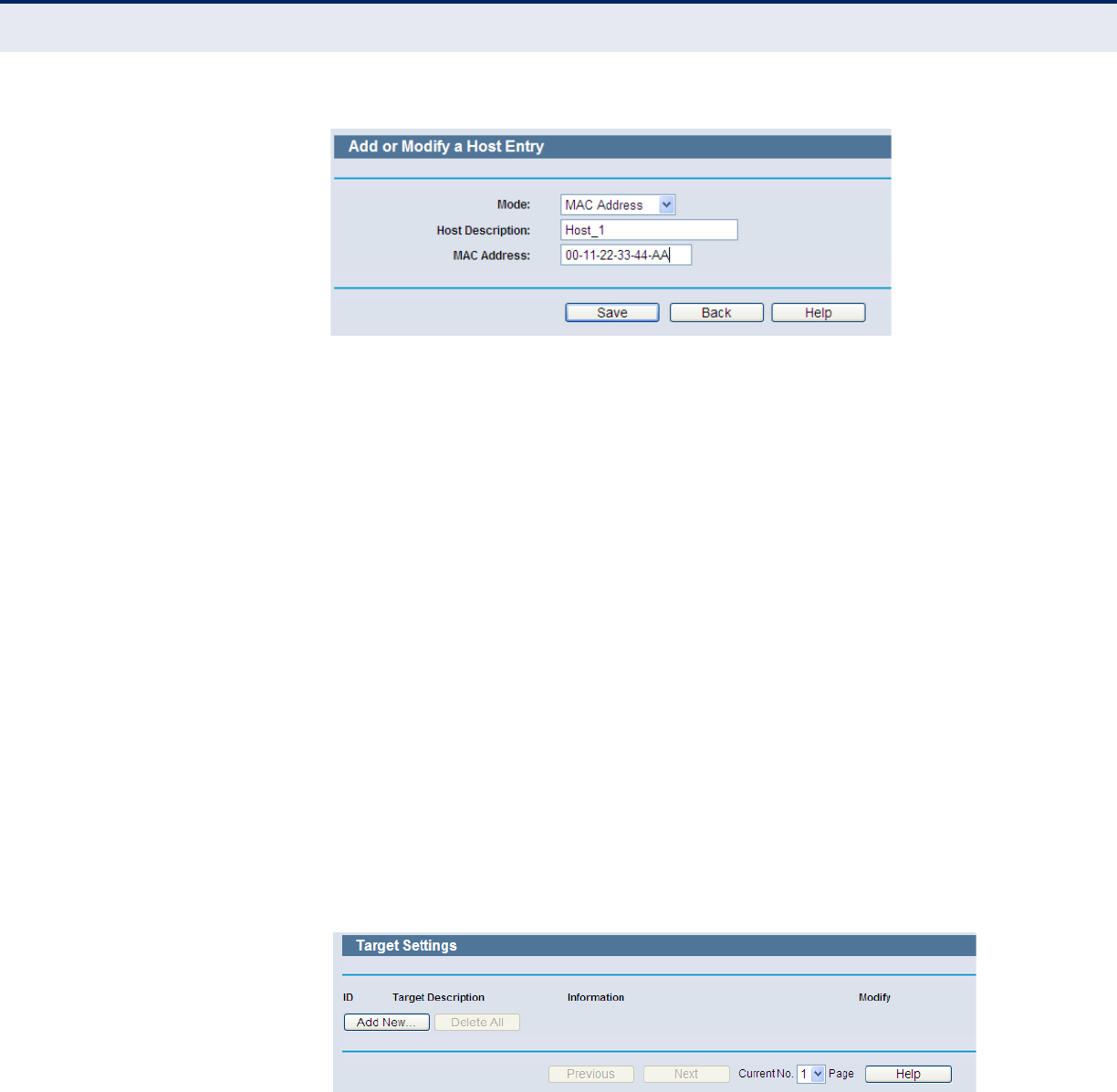
C
HAPTER
4
| Configuring the Router
Access Control
– 94 –
Figure 92: Add or Modify a MAC Host Entry
For example: If you desire to restrict the internet activities of host with
MAC address 00-11-22-33-44-AA, you should first follow the settings
below:
1. Click “Add New” button in Figure 90 to enter the “Add or Modify a Host
Entry” page.
2. In Mode field, select MAC Address from the drop-down list.
3. In Host Description field, create a unique description for the host (e.g.
Host_1).
4. In MAC Address field, enter 00-11-22-33-44-AA.
5. Click Save to complete the settings.
Then you will go back to the Host Settings page and see the following list.
TARGET Select Access Control -> Target from the menu; you can view and set a
Target list in the screen, as shown in Figure 93. The target list is necessary
for Access Control Rules.
Figure 93: Target Settings
◆Target Description - Here displays the description about the target
and this description is unique.
◆Information - The target can be IP address, port, or domain name.
◆Modify - To modify or delete an existing entry.
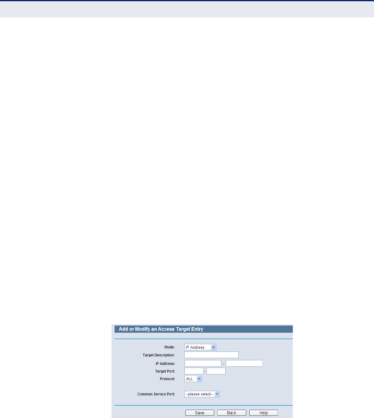
C
HAPTER
4
| Configuring the Router
Access Control
– 95 –
To add a new entry, follow the steps below.
1. Click the “Add New” button.
2. In Mode field, select IP Address or Domain Name.
a. If you select IP Address, the screen in Figure 94 is shown.
●In Target Description field, create a unique description for the
target (e.g. Target_1).
●In IP Address field, enter the IP address of the target.
●Select a common service from Common Service Port drop-down
list, so that the Target Port will be automatically filled. If the
Common Service Port drop-down list doesn’t have the service
you want, specify the Target Port manually.
●In Protocol field, select TCP, UDP, ICMP or ALL.
b. If you select Domain Name, the screen in Figure 95 is shown.
●In Target Description field, create a unique description for the
target (e.g. Target_1).
●In Domain Name field, enter the domain name, either the full
name or the keywords (for example google) in the blank. Any
domain name with keywords in it (www.google.com,
www.google.cn) will be blocked or allowed. You can enter 4
domain names.
3. Click the Save button.
Click the Delete All button to delete all the entries in the table.
Click the Next button to go to the next page, or click the Previous button
return to the previous page.
Figure 94: Add or Modify an IP Access Target Entry
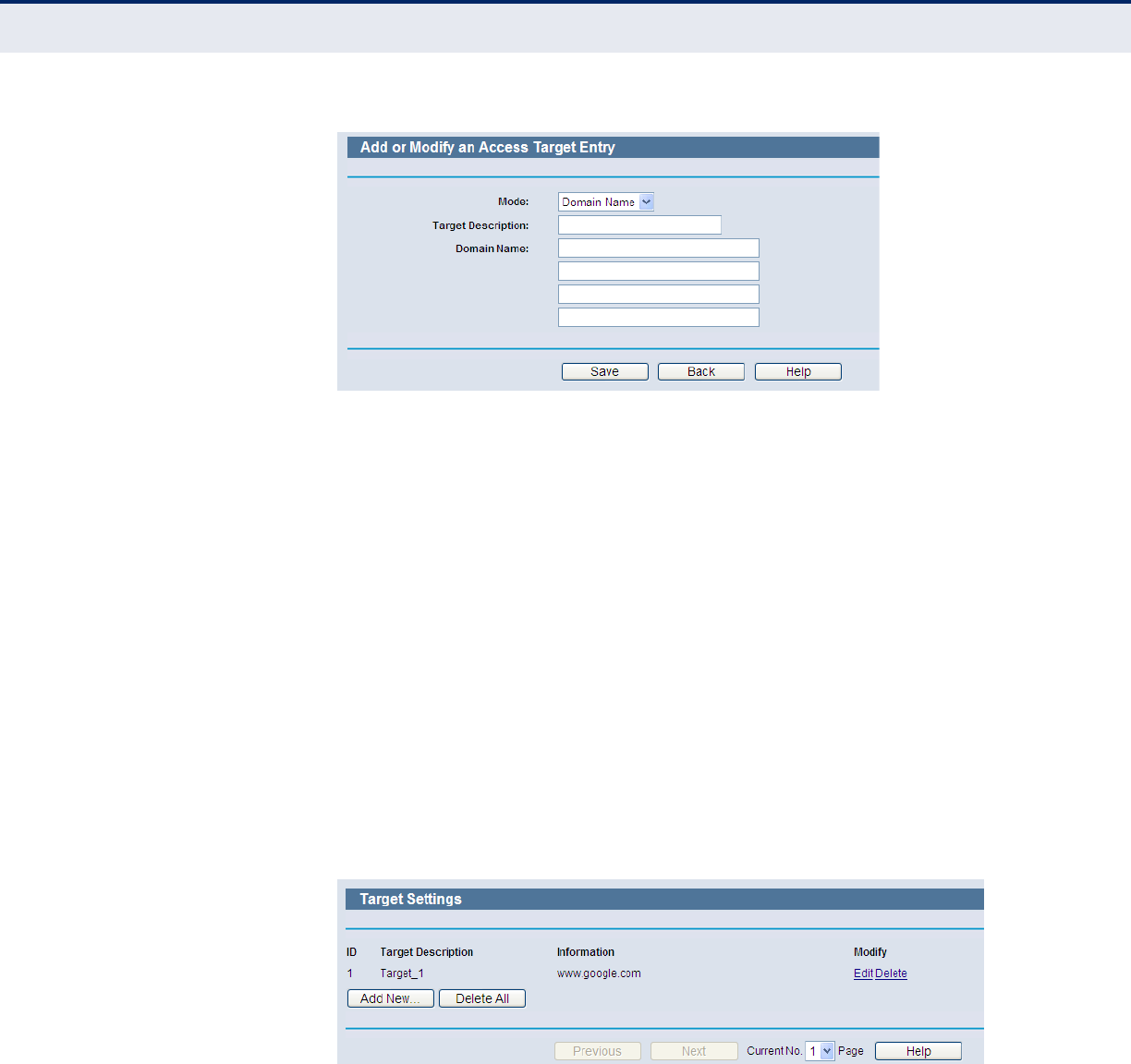
C
HAPTER
4
| Configuring the Router
Access Control
– 96 –
Figure 95: Add or Modify a Domain Name Access Target Entry
For example: If you desire to restrict the internet activities of a host with
MAC address 00-11-22-33-44-AA in the LAN to access www.google.com
only, you should first follow the settings below:
1. Click the “Add New” button in Figure 93 to enter the Add or Modify an
Access Target Entry page.
2. In Mode field, select Domain Name from the drop-down list.
3. In Target Description field, create a unique description for the target
(e.g. Target_1).
4. In Domain Name field, enter www.google.com.
5. Click Save to complete the settings.
Then you will go back to the Target Settings page and see the following list.
Figure 96: Target Setting
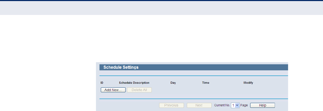
C
HAPTER
4
| Configuring the Router
Access Control
– 97 –
SCHEDULE Select Access Control -> Schedule from the menu; you can view and set
a schedule list in the next screen, as shown in Figure 97. The schedule list
is necessary for Access Control Rules.
Figure 97: Schedule Settings
◆Schedule Description - Here displays the description of the schedule
and this description is unique.
◆Day - Here displays the day(s) in a week.
◆Time - Here displays the time period in a day.
◆Modify - Here you can edit or delete an existing schedule.
To add a new schedule, follow the steps below.
1. Click the “Add New” button shown in Figure 97 and the next screen will
pop-up as shown in Figure 98.
2. In Schedule Description field, create a unique description for the
schedule (e.g. Schedule_1).
3. In Day field, select the day or days you need.
4. In Time field, you can select all day-24 hours or you may enter the
Start Time and Stop Time in the corresponding field.
5. Click Save to complete the settings.
Click the Delete All button to delete all the entries in the table.
Click the Next button to go to the next page, or click the Previous button
return to the previous page.
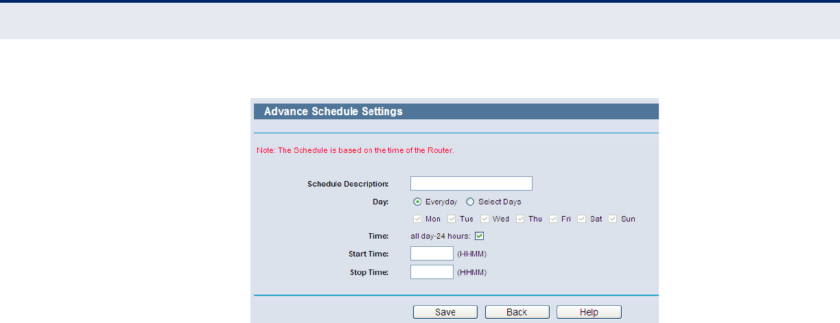
C
HAPTER
4
| Configuring the Router
Access Control
– 98 –
Figure 98: Advanced Schedule Settings
For example: If you desire to restrict the internet activities of host with
MAC address 00-11-22-33-44-AA to access www.google.com only from
18:00 to 20:00 on Saturday and Sunday, you should first follow the
settings below:
1. Click the “Add New” button shown in Figure 98 to enter the Advanced
Schedule Settings page.
2. In Schedule Description field, create a unique description for the
schedule (e.g. Schedule_1).
3. In Day field, check the Select Days radio button and then select Sat and
Sun.
4. In Time field, enter 1800 in Start Time field and 2000 in Stop Time
field.
5. Click Save to complete the settings.
Then you will go back to the Schedule Settings page and see the following
list.
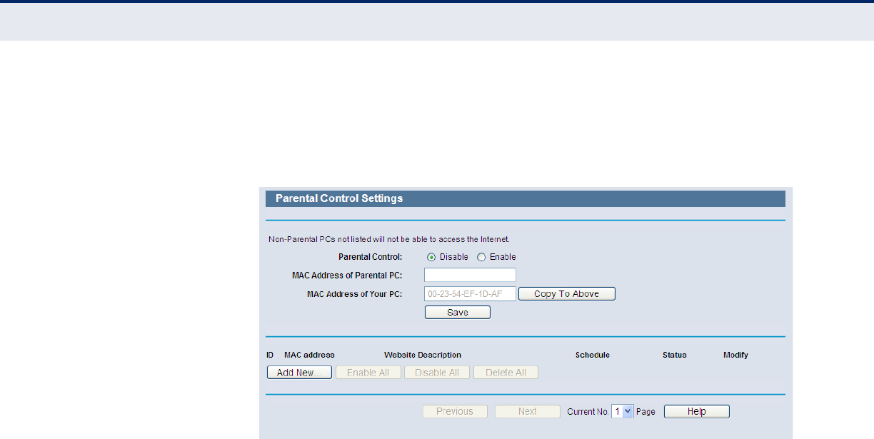
C
HAPTER
4
| Configuring the Router
Access Control
– 99 –
PARENTAL CONTROL Select Parental Control from the menu; you can then configure the
parental control in the displayed page, as shown in Figure 99. The Parental
Control function can be used to limit children’s access to certain websites
and restrict the time of surfing.
Figure 99: Parental Control Settings
◆Parental Control - Check Enable if you want this function to take
effect, otherwise check Disable.
◆MAC Address of Parental PC - In this field, enter the MAC address of
the controlling PC, or you can make use of the “Copy To Above” button
below.
◆MAC Address of Your PC - This field displays the MAC address of the
PC that is managing this Router. If the MAC Address of your adapter is
registered, you can click the “Copy To Above” button to fill this address
to the MAC Address of Parental PC field above.
◆Website Description - Description of the allowed website for the child
PC.
◆Schedule - The time period allowed for the PC controlled to access the
Internet. For detailed information, please go to “Access Control ->
Schedule”.
◆Modify - Here you can edit or delete an existing entry.
To add a new entry, please follow the steps below.
1. Click the “Add New” button and the next screen will pop-up, as shown
in Figure 100.
2. Enter the MAC address of the PC (e.g. 00-11-22-33-44-AA) you want to
control in the “MAC Address of Child PC” field. Or you can choose the
MAC address from the “All Address in Current LAN” drop-down list.
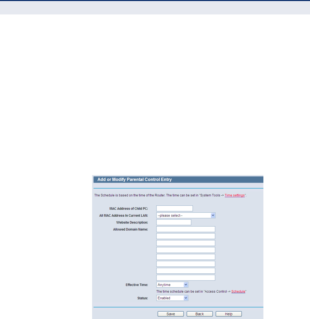
C
HAPTER
4
| Configuring the Router
Access Control
– 100 –
3. Give a description (e.g. Allow Google) for the website allowed to be
accessed in the Website Description field.
4. Enter the allowed domain name of the website, either the full name or
the keywords (e.g. google) in the Allowed Domain Name field. Any
domain name with keywords in it (www.google.com.cn) will be allowed.
5. Select from the “Effective Time” drop-down list the schedule (e.g.
Schedule_1) you want the entry to take effect. If there are not suitable
schedules for you, click the Schedule in red below to go to the Advance
Schedule Settings page and create the schedule you need.
6. In the Status field, you can select Enabled or Disabled to enable or
disable your entry.
7. Click the Save button.
Click the Enable All button to enable all the rules in the list.
Click the Disable All button to disable all the rules in the list.
Click the Delete All button to delete all the entries in the table.
Click the Next button to go to the next page, or click the Previous
button return to the previous page.
Figure 100: Add or Modify Parental Control Entry
For example: If you desire that the child PC with MAC address 00-11-22-
33-44-AA can access www.google.com on Saturday only while the parent
PC with MAC address 00-11-22-33-44-BB is without any restriction, you
should follow the settings below.
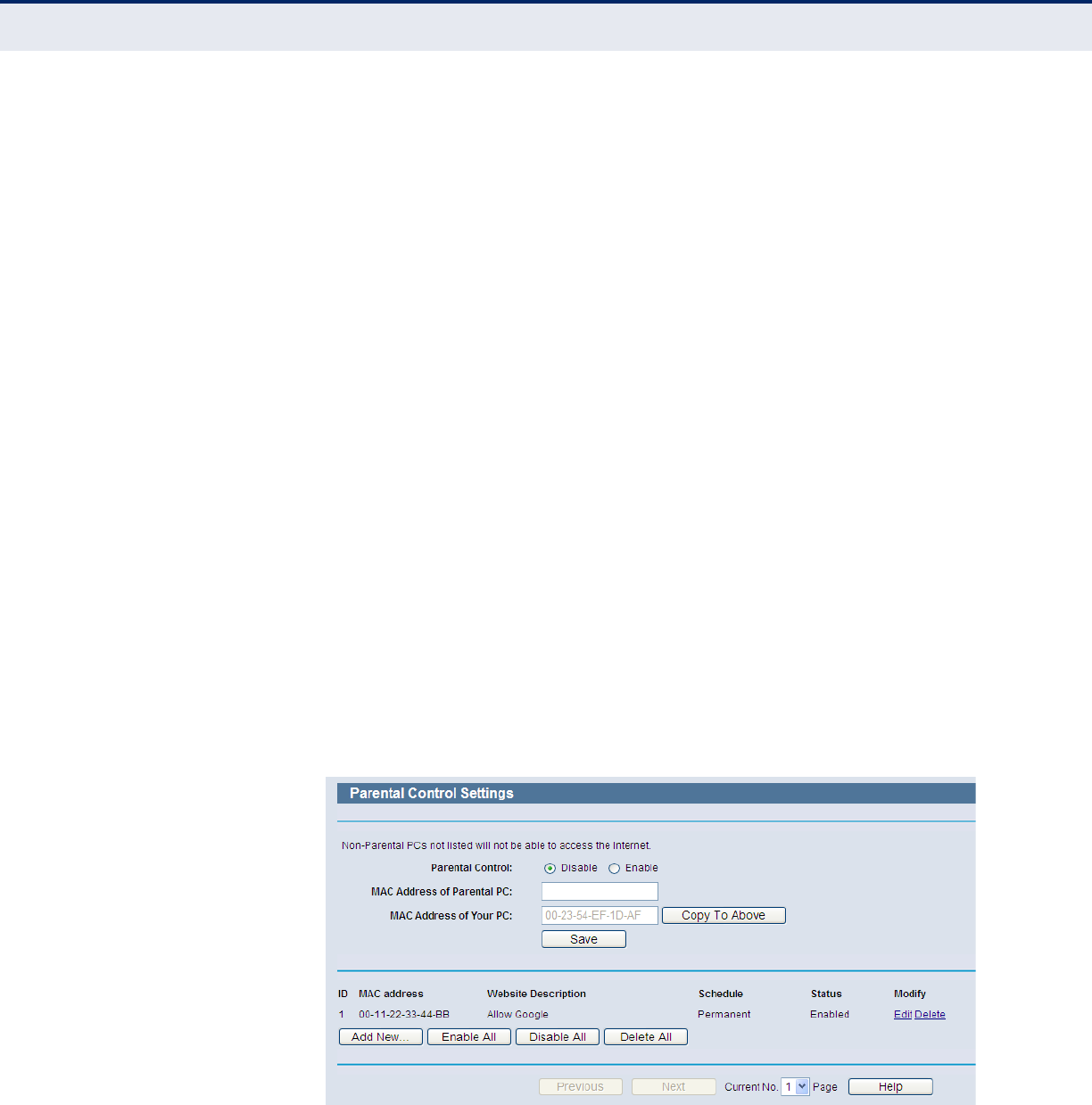
C
HAPTER
4
| Configuring the Router
Access Control
– 101 –
1. Click Parental Control on the menu to enter the Parental Control
Settings page. Check Enable and enter the MAC address 00-11-22-33-
44-BB in the “MAC Address of Parental PC” field.
2. Click Access Control -> Schedule on the left to enter the Schedule
Settings page. Click the “Add New” button to create a new schedule
with Schedule Description “Schedule_1,” Day is “Sat” and Time is all
day-24 hours.
3. Click “Parental Control” menu on the left to go back to the Add or
Modify Parental Control Entry page:
■Click the “Add New” button.
■Enter 00-11-22-33-44-AA in the MAC Address of Child PC field.
■Enter “Allow Google” in the Website Description field.
■Enter “www.google.com” in the Allowed Domain Name field.
■Select “Schedule_1” you create just now from the Effective Time
drop-down list.
■In Status field, select Enable.
4. Click Save to complete the settings.
Then you will go back to the Parental Control Settings page and see the
following list, as shown in Figure 101.
Figure 101: Parental Control Settings
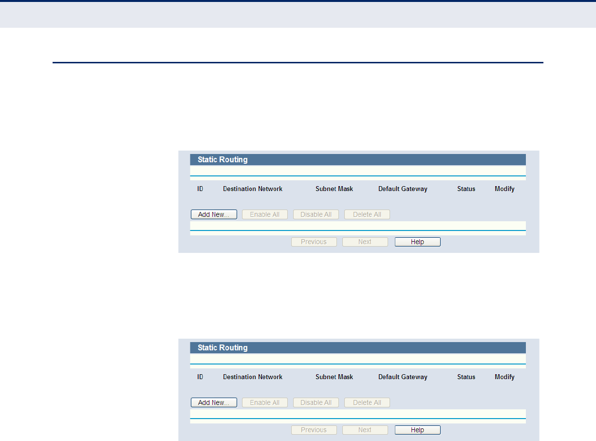
C
HAPTER
4
| Configuring the Router
Advanced Routing
– 102 –
ADVANCED ROUTING
Select static routing from the menu; you can configure the static route in
the next screen (Figure 102). A static route is a pre-determined path that
network information must travel to reach a specific host or network.
Figure 102: Static Routing
To add static routing entries:
1. Click Add New.
Figure 103: Add or Modify a Static Route Entry
2. Enter the following data:
◆Destination IP Address - The Destination IP Address is the address
of the network or host that you want to assign to a static route.
◆Subnet Mask - The Subnet Mask determines which portion of an IP
Address is the network portion, and which portion is the host portion.
◆Gateway - This is the IP Address of the gateway device that allows for
contact between the Router and the network or host.
3. Select Enabled or Disabled for this entry on the Status pull-down list.
4. Click the Save button to make the entry take effect.
Other configurations for the entries:
Click the Delete button to delete the entry.
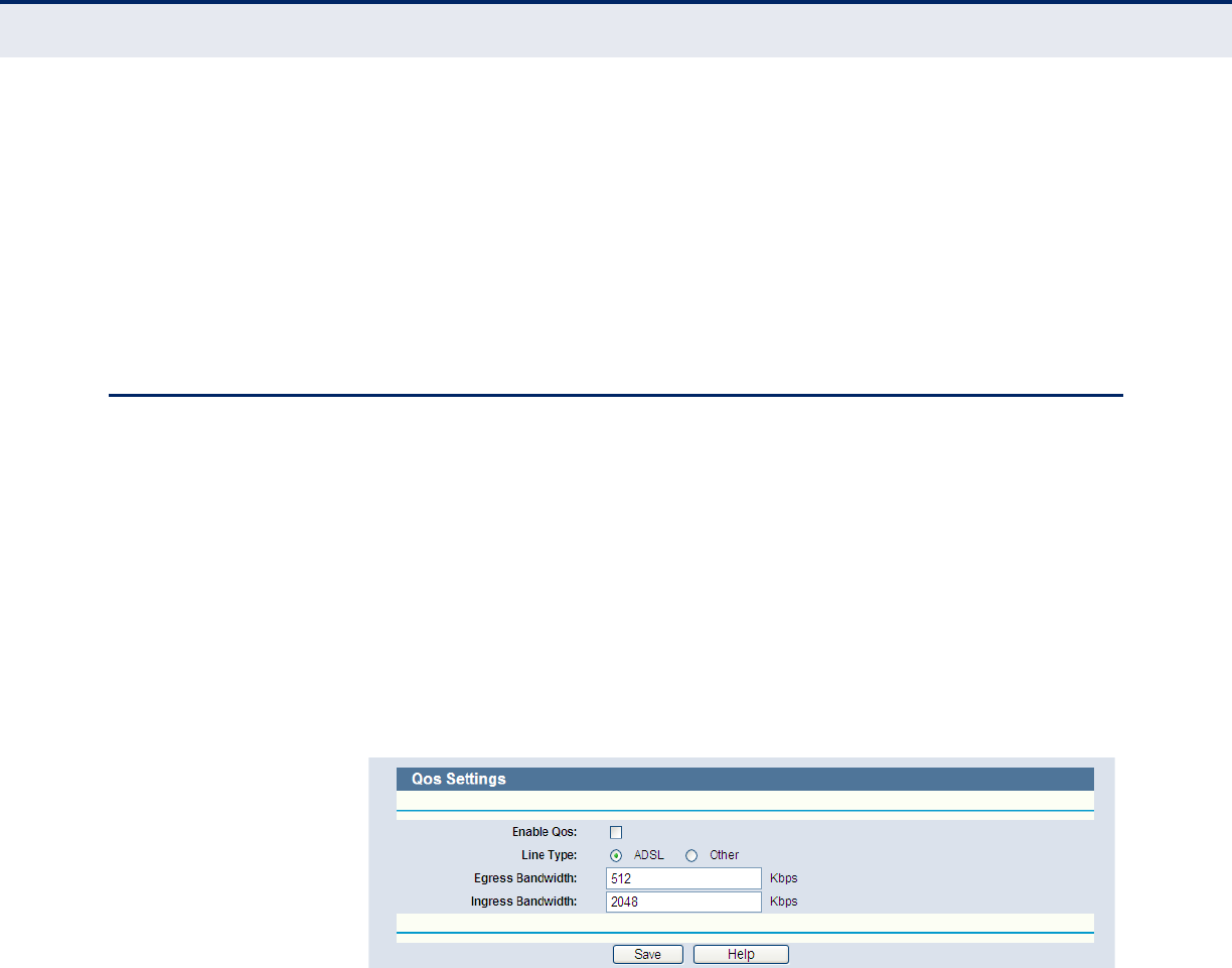
C
HAPTER
4
| Configuring the Router
QoS Settings
– 103 –
Click the Enable All button to enable all the entries.
Click the Disable All button to disable all the entries.
Click the Delete All button to delete all the entries.
Click the Previous button to view the information in the previous screen.
Click the Next button to view the information in the next screen.
QOS SETTINGS
There are two submenus under the QoS menu, as shown in Figure 104.
Click any of them and you will be able to configure the corresponding
function. The detailed explanations for each submenu are provided below.
QOS SETTINGS Select QoS->QoS Settings from the menu; you can configure the Egress
Bandwidth and Ingress Bandwidth in the next screen. The values you
configure should be less than 100000 Kbps. For optimal control of the
bandwidth, please select the right Line Type and ask your ISP for the total
bandwidth of the egress and ingress.
Figure 104: QoS Settings
◆Enable QoS - Check this box so that the QoS settings can take effect.
◆Line Type - Select the right type for you network connection. If you do
not know which type to choose, ask your ISP for the information.
◆Egress Bandwidth - The upload speed through the WAN port.
◆Ingress Bandwidth - The download speed through the WAN port.
RULES LIST Select QoS->Rules List from the menu; you can view and configure the
QoS rules in the screen below.
◆Description - This is the information about the rules such as address
range.
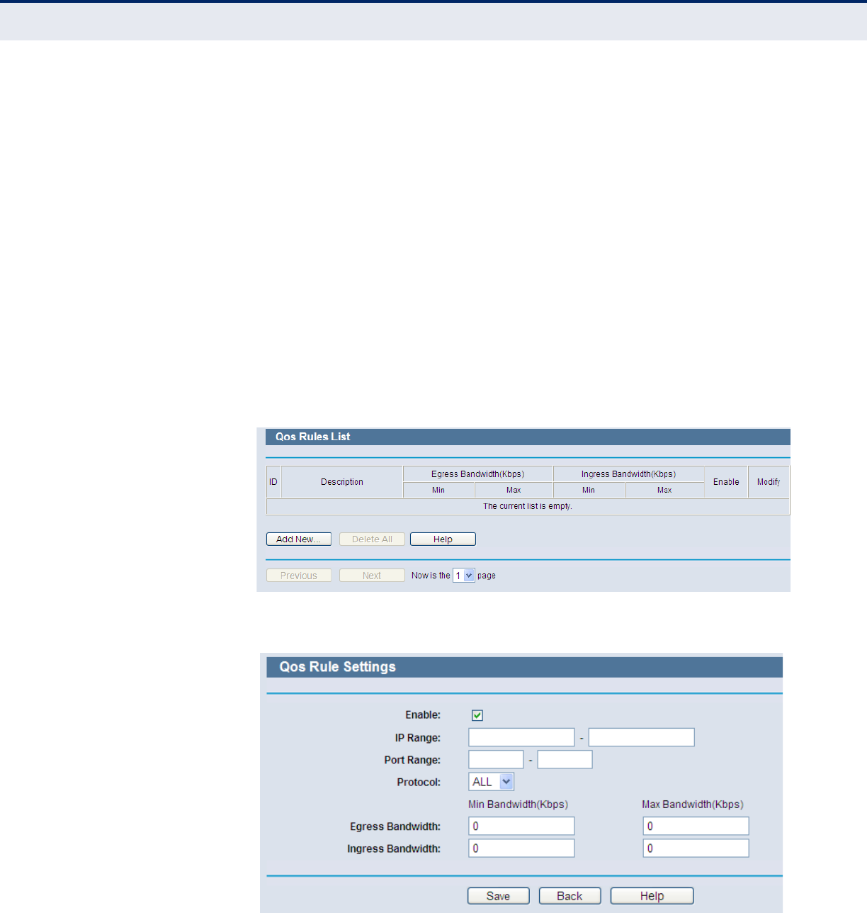
C
HAPTER
4
| Configuring the Router
QoS Settings
– 104 –
◆Egress bandwidth - This field displays the maximum and minimum
upload bandwidth through the WAN port, the default is 0.
◆Ingress bandwidth - This field displays the maximum and minimum
download bandwidth through the WAN port, the default is 0.
◆Enable - This displays the status of the rule.
◆Modify - Click Modify to edit the rule. Click Delete to delete the rule.
To add/modify a QoS rule, follow the steps below.
1. Click “Add New,” as shown in Figure 105, you will see a new screen
shown in Figure 106.
2. Enter the information like the screen shown below.
3. Click the Save button.
Figure 105: QoS Rule List
Figure 106: Qos Rule Settings
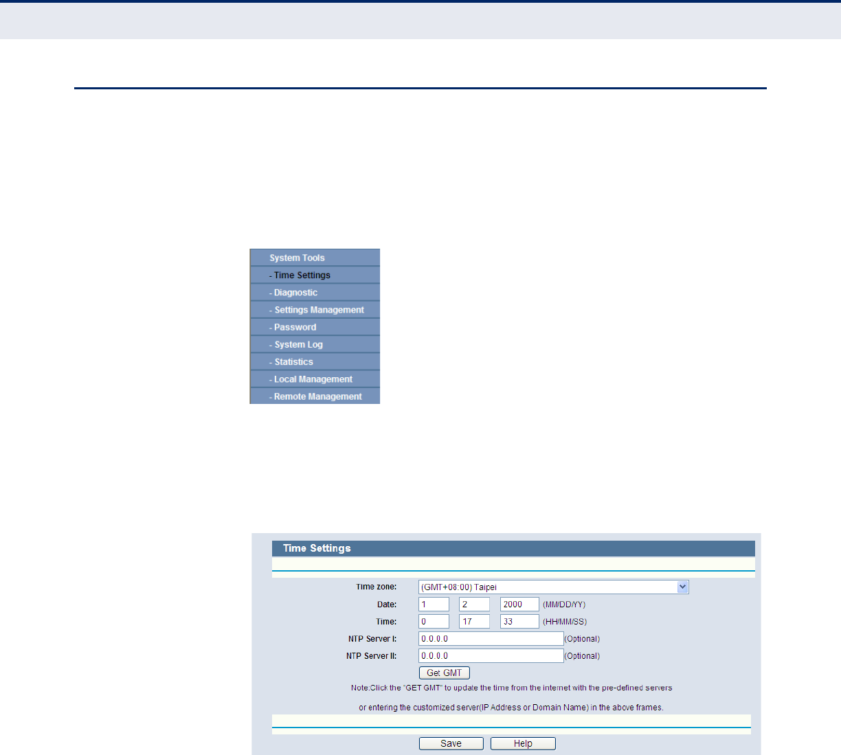
C
HAPTER
4
| Configuring the Router
System Tools
– 105 –
SYSTEM TOOLS
Select System Tools, and you can see the submenus under the main
menu: Time Settings, Diagnostic, Settings Management, Password, System
Log, Statistics, Local Management, and Remote Management. Click any of
them, and you will be able to configure the corresponding function. The
detailed explanations for each submenu are provided below.
Figure 107: The System Tools Menu
TIME SETTINGS Select System Tools->Time Setting from the menu; you can configure
the time on the following screen.
Figure 108: Time Settings
◆Time Zone - Select your local time zone from this pull down list.
◆Date - Enter your local date in MM/DD/YY into the right blanks.
◆Time - Enter your local time in HH/MM/SS into the right blanks.
◆NTP Server Prior - Enter the address for the NTP Server, then the
Router will get the time from the NTP Server preferentially. In addition,
the Router includes some common NTP Servers, so it can get the time
automatically once it connects the Internet.
C
HAPTER
4
| Configuring the Router
System Tools
– 106 –
To configure the system manually:
1. Select your local time zone.
2. Enter date and time in the right blanks.
3. Click Save to save the configuration.
To configure the system automatically:
1. Select your local time zone.
2. Enter the IP address for NTP Server Prior.
3. Click the Get GMT button to get system time from Internet if you have
connected to the Internet.
N
OTE
:
This setting will be used for some time-based functions such as the
firewall. You must specify your time zone once you login to the router
successfully, otherwise these functions will not take effect.
N
OTE
:
The time will be lost if the router is turned off.
N
OTE
:
The router will obtain GMT automatically from Internet if it has been
already connected to the Internet.
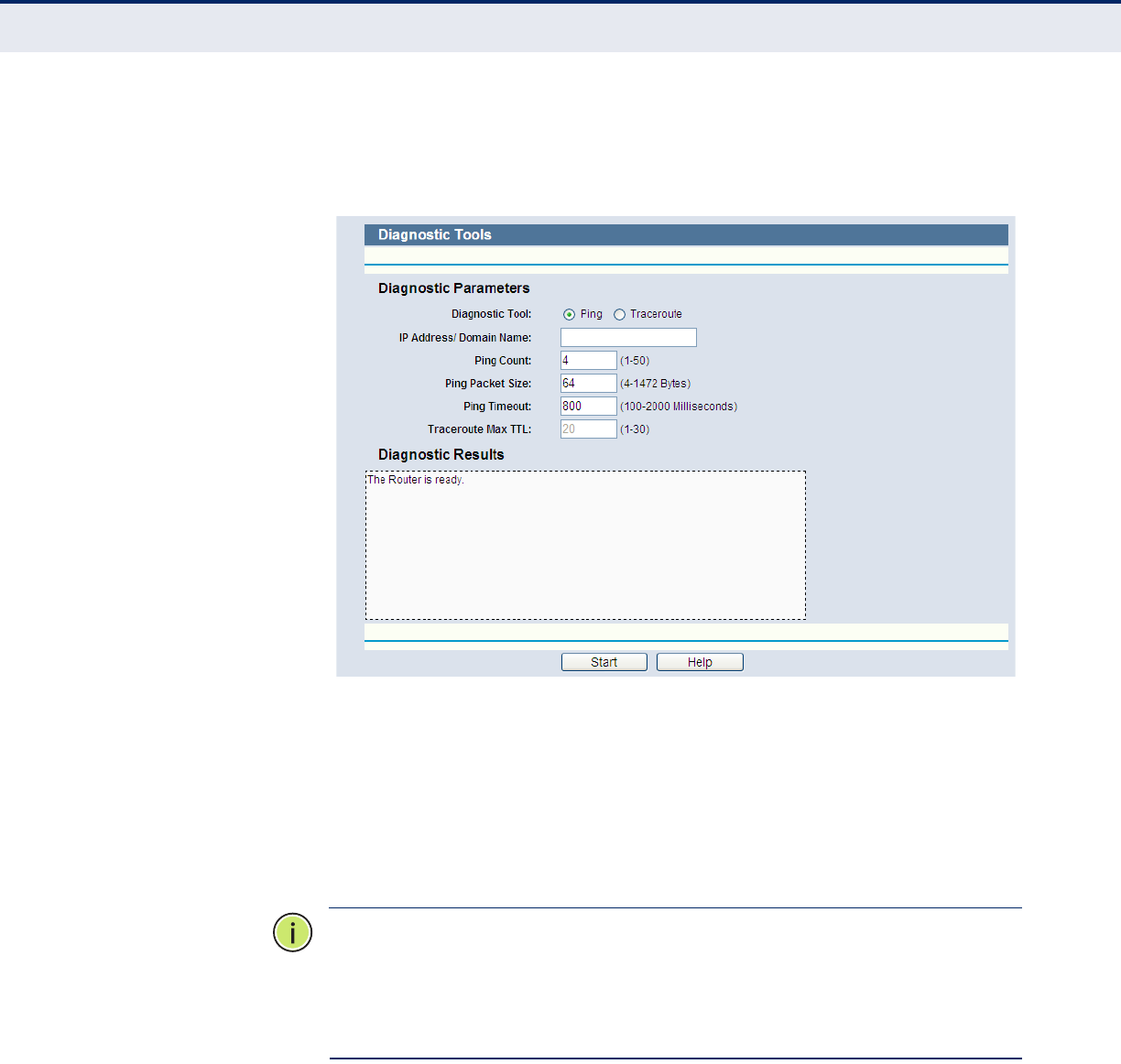
C
HAPTER
4
| Configuring the Router
System Tools
– 107 –
DIAGNOSTIC Select System Tools->Diagnostic from the menu; you can use Ping or
Traceroute functions to check connectivity of your network in the following
screen.
Figure 109: Diagnostic Tools
◆Diagnostic Tool - Check the radio button to select one diagnostic too.
■Ping - This diagnostic tool troubleshoots connectivity, reachability,
and name resolution to a given host or gateway.
■Traceroute - This diagnostic tool tests the performance of a
connection.
N
OTE
:
You can use ping/traceroute to test both numeric IP address or
domain name. If pinging/tracerouting the IP address is successful, but
pinging/tracerouting the domain name is not, you might have a name
resolution problem. In this case, ensure that the domain name you are
specifying can be resolved by using Domain Name System (DNS) queries.
◆IP Address/Domain Name - Type the destination IP address (such as
202.108.22.5) or Domain name (such as http://www.smc.com)
◆Pings Count - The number of Ping packets for a Ping connection.
◆Ping Packet Size - The size of Ping packet.
◆Ping Timeout - Set the waiting time for the reply of each Ping packet.
If there is no reply in the specified time, the connection is overtime.
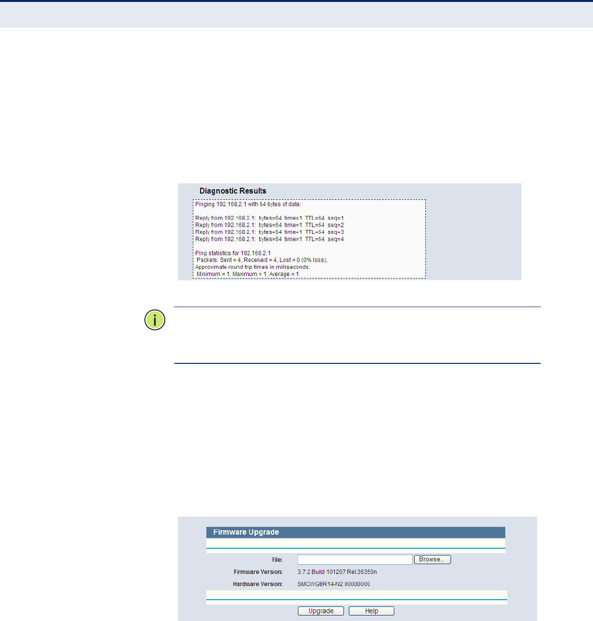
C
HAPTER
4
| Configuring the Router
System Tools
– 108 –
◆Traceroute Max TTL - The max number of hops for a Traceroute
connection.
Click Start to check the connectivity of the Internet.
The Diagnostic Results page displays the result of diagnosis.
If the result is similar to the following screen, the connectivity of the
Internet is fine.
Figure 110: Diagnostic Results
N
OTE
:
Only one user can use this tool at one time. Options “Number of
Pings”, “Ping Size” and “Ping Timeout” are used for the Ping function.
Option “Tracert Hops” is used for the Tracert function.
SETTINGS
MANAGEMENT
The Settings Management page includes Firmware Upgrade, Factory
Defaults, Backup & Restore, and Reboot.
FIRMWARE UPGRADE
Select System Tools->Firmware Upgrade from the menu; you can
update the latest version of firmware for the Router on the following
screen.
Figure 111: Firmware Upgrade
◆Firmware Version - This displays the current firmware version.
C
HAPTER
4
| Configuring the Router
System Tools
– 109 –
◆Hardware Version - This displays the current hardware version. The
hardware version of the upgrade file must accord with the Router’s
current hardware version.
To upgrade the Router's firmware, follow the instructions below:
1. Download a more recent firmware upgrade file from the SMC website
(http://www.smc.com).
2. Type the path and file name of the update file into the File field. Or click
the Browse button to locate the update file.
3. Click the Upgrade button.
N
OTE
:
New firmware versions are posted at http://www.smc.com and can
be downloaded for free. There is no need to upgrade the firmware unless
the new firmware has a new feature you want to use. However, when
experiencing problems caused by the Router rather than the configuration,
you can try to upgrade the firmware.
N
OTE
:
When you upgrade the Router's firmware, you may lose its current
configuration, so before upgrading the firmware write down some of your
customized settings to avoid losing them.
N
OTE
:
Do not turn off the Router or press the Reset button while the
firmware is being upgraded, otherwise, the Router may be damaged.
N
OTE
:
The Router will reboot after the upgrading has been finished.
FACTORY DEFAULTS
Select System Tools-> Factory Defaults from the menu; you can
restore the configuration of the Router to factory defaults on the following
screen.
Figure 112: Restore Factory Default
Click the Restore button to reset all configuration settings to their default
values.
◆The default User Name: admin
◆The default Password: smcadmin
◆The default IP Address: 192.168.2.1
C
HAPTER
4
| Configuring the Router
System Tools
– 110 –
◆The default Subnet Mask: 255.255.255.0
N
OTE
:
Any settings you have saved will be lost when the default settings
are restored.
BACKUP & RESTORE
Select System Tools-> Backup & Restore from the menu; you can save
the current configuration of the Router as a backup file and restore the
configuration via a backup file as shown in Figure 113.
Figure 113: Backup & Restore Configuration
◆Click the Backup button to save all configuration settings as a backup
file in your local computer.
◆To upgrade the Router's configuration, follow these instructions.
■Click the Browse… button to locate the update file for the Router, or
enter the exact path to the Setting file in the text box.
■Click the Restore button.
N
OTE
:
The current configuration will be covered by the uploading
configuration file. The upgrade process lasts for 20 seconds and the Router
will restart automatically. Keep the Router on during the upgrading process
to prevent any damage.
C
HAPTER
4
| Configuring the Router
System Tools
– 111 –
REBOOT
Select System Tools->Reboot from the menu; you can click the Reboot
button to reboot the Router via the next screen.
Figure 114: Reboot
Some settings of the Router will take effect only after rebooting, which
include
◆Change of the LAN IP Address (system will reboot automatically).
◆Change of DHCP Settings.
◆Change of Wireless configurations.
◆Change of the Web Management Port.
◆Upgrade of the Router firmware (system will reboot automatically).
◆Restore the Router's settings to factory defaults (system will reboot
automatically).
◆Update the configuration from a file (system will reboot automatically.
PASSWORD Select System Tools->Password from the menu; you can change the
factory default user name and password of the Router in the next screen as
shown in Figure 115.
Figure 115: Password
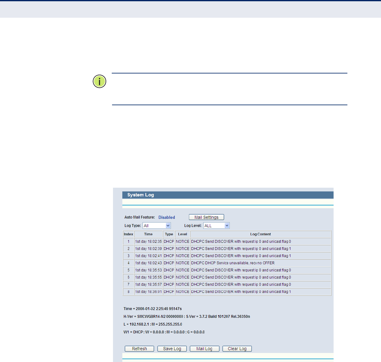
C
HAPTER
4
| Configuring the Router
System Tools
– 112 –
It is strongly recommended that you should change the factory default
user name and password of the Router, because all users who try to access
the Router's Web-based utility or Quick Setup will be prompted for the
Router's default user name and password.
N
OTE
:
The new user name and password must not exceed 14 characters in
length and not include any spaces. Enter the new Password twice to
confirm.
Click the Save button when finished.
Click the Clear All button to clear all.
SYSTEM LOG Selct System Tools->System Log from the menu; you can view the logs
of the Router.
Figure 116: System Log
◆Auto Mail Feature - Indicates whether auto mail feature is enabled or
not.
◆Mail Settings - Set the receiving and sending mailbox address, server
address, validation information as well as the timetable for Auto Mail
Feature, as shown in Figure 117.
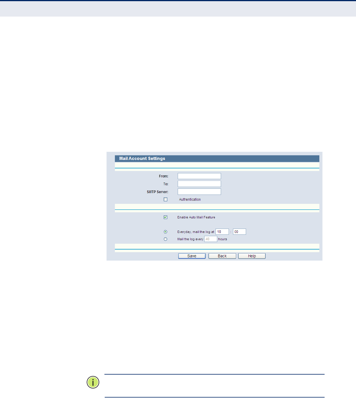
C
HAPTER
4
| Configuring the Router
System Tools
– 113 –
◆Log Type - By selecting the log type, only logs of this type will be
shown.
◆Log Level - By selecting the log level, only logs of this level will be
shown.
◆Refresh - Refresh the page to show the latest log list.
◆Save Log - Click to save all the logs in a txt file.
◆Mail Log - Click to send an email of current logs manually according to
the address and validation information set in Mail Settings.
◆Clear Log - All the logs will be deleted from the Router permanently,
not just from the page.
Figure 117: Mail Account Settings
◆From - Your mail box address. The Router would connect it to send
logs.
◆To - Recipient’s address. The destination mailbox where the logs would
be received.
◆SMTP Server - Your smtp server. It corresponds with the mailbox filled
in the From field. You can log on the relevant website for Help if you are
not clear with the address.
◆Authentication - Most SMTP Server requires Authentication. It is
required by most mailboxes that need User Name and Password to log
in.
N
OTE
:
Only when you select Authentication, do you have to enter the User
Name and Password in the following fields.
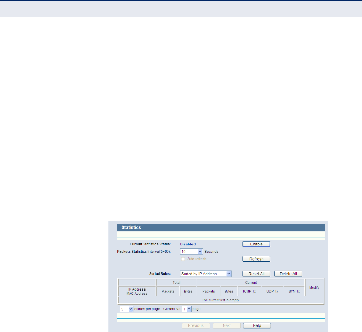
C
HAPTER
4
| Configuring the Router
System Tools
– 114 –
◆User Name - Your mail account name filled in the From field. The part
after @ is excluded.
◆Password - Your mail account password.
◆Confirm The Password - Enter the password again to confirm.
◆Enable Auto Mail Feature - Select it to mail logs automatically. You
could mail the current logs either at a specified time everyday or by
intervals, but only one could be the current effective rule. Enter the
desired time or intervals in the corresponding field as shown in
Figure 117.
Click Save to keep your settings.
Click Back to return to the previous page.
Click the Next button to go to the next page, or click the Previous button
return to the previous page.
STATISTICS Select System Tools->Statistics from the menu; you can view the
statistics of the Router, including total traffic and current traffic of the last
Packets Statistic Interval.
Figure 118: Statistics
◆Current Statistics Status - Enable or Disable. The default value is
disabled. To enable, click the Enable button.
◆Packets Statistics Interval (5-60) - The default value is 10. Select a
value between 5 and 60 seconds in the pull-down list. The Packets
Statistic interval indicates the time section of the packets statistic.
Select the Auto-refresh checkbox to refresh automatically.
Click the Refresh button to refresh immediately.

C
HAPTER
4
| Configuring the Router
System Tools
– 115 –
◆Sorted Rules - Select a rule from the pull-down list to display the
corresponding statistics..
Click Reset All to reset the values of all the entries to zero.
Click Delete All to delete all entries in the table.
Statistics Table:
IP/MAC Address - The IP/MAC Address displayed with statistics
Total Packets - The total amount of packets received and transmitted by
the Router.
Total Bytes - The total amount of bytes received and transmitted by the
Router.
Current Packets - The total amount of packets received and transmitted
in the last Packets Statistic interval seconds.
Current Bytes - The total amount of bytes received and transmitted in the
last Packets Statistic interval seconds.
Current ICMP Tx - The total amount of the ICMP packets transmitted to
WAN in the last Packets Statistic interval seconds.
Current UDP Tx - The total amount of the UDP packets transmitted to
WAN in the last Packets Statistic interval seconds.
Current TCP SYN Tx - The total amount of the TCP SYN packets
transmitted to WAN in the last Packets Statistic interval seconds.
There are 5 entries on each page. Click Previous to return to the previous
page and Next to the next page.
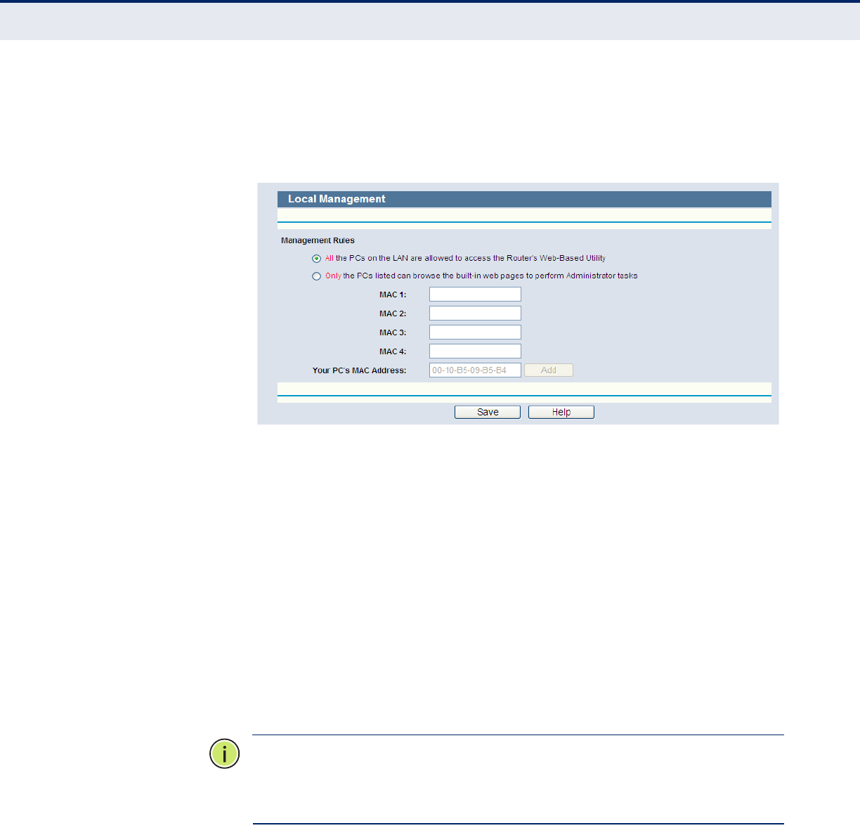
C
HAPTER
4
| Configuring the Router
System Tools
– 116 –
LOCAL MANAGEMENT Select Security->Local Management from the menu; you can configure
the management rules in the screen, as shown in Figure 119. The
management feature allows you to deny computers in the LAN from
accessing the Router.
Figure 119: Local Management
By default, the radio button “All the PCs on the LAN are allowed to access
the Router's Web-Based Utility” is checked. If you want to allow PCs with
specific MAC Addresses to access the Setup page of the Router's Web-
Based Utility locally from inside the network, check the radio button “Only
the PCs listed can browse the built-in web pages to perform Administrator
tasks”, and then enter each MAC Address in a separate field. The format for
the MAC Address is XX-XX-XX-XX-XX-XX (X is any hexadecimal digit). Only
the PCs with MAC address listed can use the password to browse the built-
in web pages to perform Administrator tasks while all the others will be
blocked.
After click the Add button, your PC's MAC Address will be placed in the list
above.
Click the Save button to save your settings.
N
OTE
:
If your PC is blocked but you want to access the Router again, use a
pin to press and hold the Reset Button (hole) on the back panel for about 5
seconds to reset the Router’s factory defaults, then access the Router’s
Web-Based Utility.
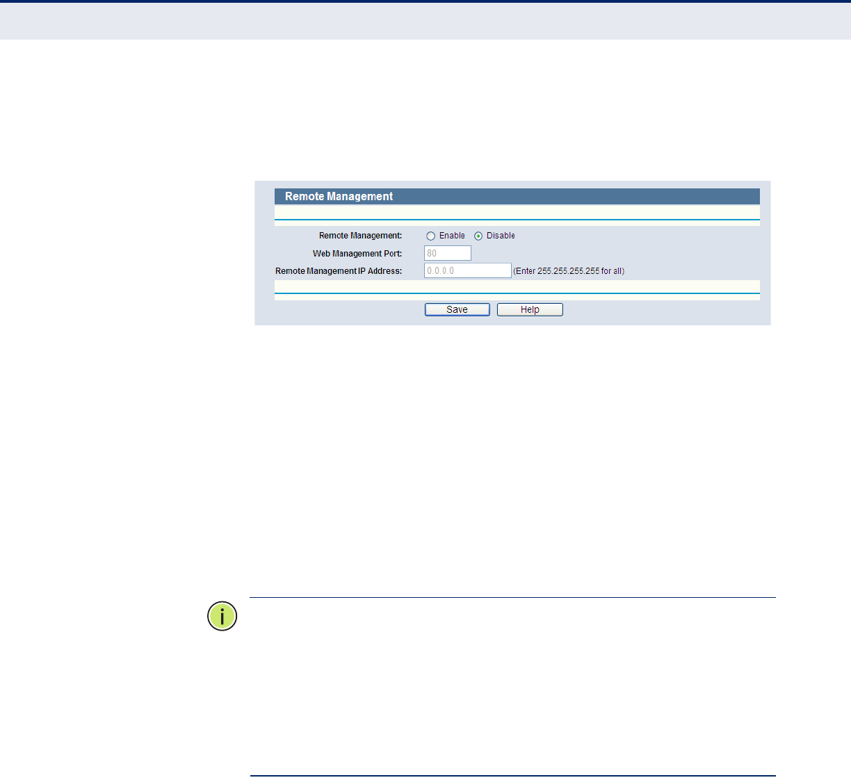
C
HAPTER
4
| Configuring the Router
System Tools
– 117 –
REMOTE
MANAGEMENT
Select Security->Remote Management from the menu; you can
configure the Remote Management function in the screen, as shown in
Figure 120. This feature allows you to manage your Router from a remote
location via the Internet.
Figure 120: Remote Management
◆Web Management Port - Web browser access normally uses the
standard HTTP service port 80. This Router's default remote
management web port number is 80. For greater security, you can
change the remote management web port to a custom port by entering
that number in the box provided. Choose a number between 1 and
65534, but do not use the number of any common service port.
◆Remote Management IP Address - This is the current address you
will use when accessing your Router from the Internet. This function is
disabled when the IP address is set to the default value of 0.0.0.0. To
enable this function change 0.0.0.0 to a valid IP address. If set to
255.255.255.255, then all the hosts can access the Router from
internet.
N
OTE
:
To access the Router, you should type your Router's WAN IP address
into your browser's address (in IE) or Location (in Navigator) box, followed
by a colon and the custom port number. For example, if your Router's WAN
address is 202.96.12.8, and the port number used is 8080, please enter
http://202.96.12.8:8080 in your browser. Later, you may be asked for the
Router's password. After successfully entering the username and
password, you will be able to access the Router's web-based utility.
N
OTE
:
Be sure to change the Router's default password to a very secure
password.
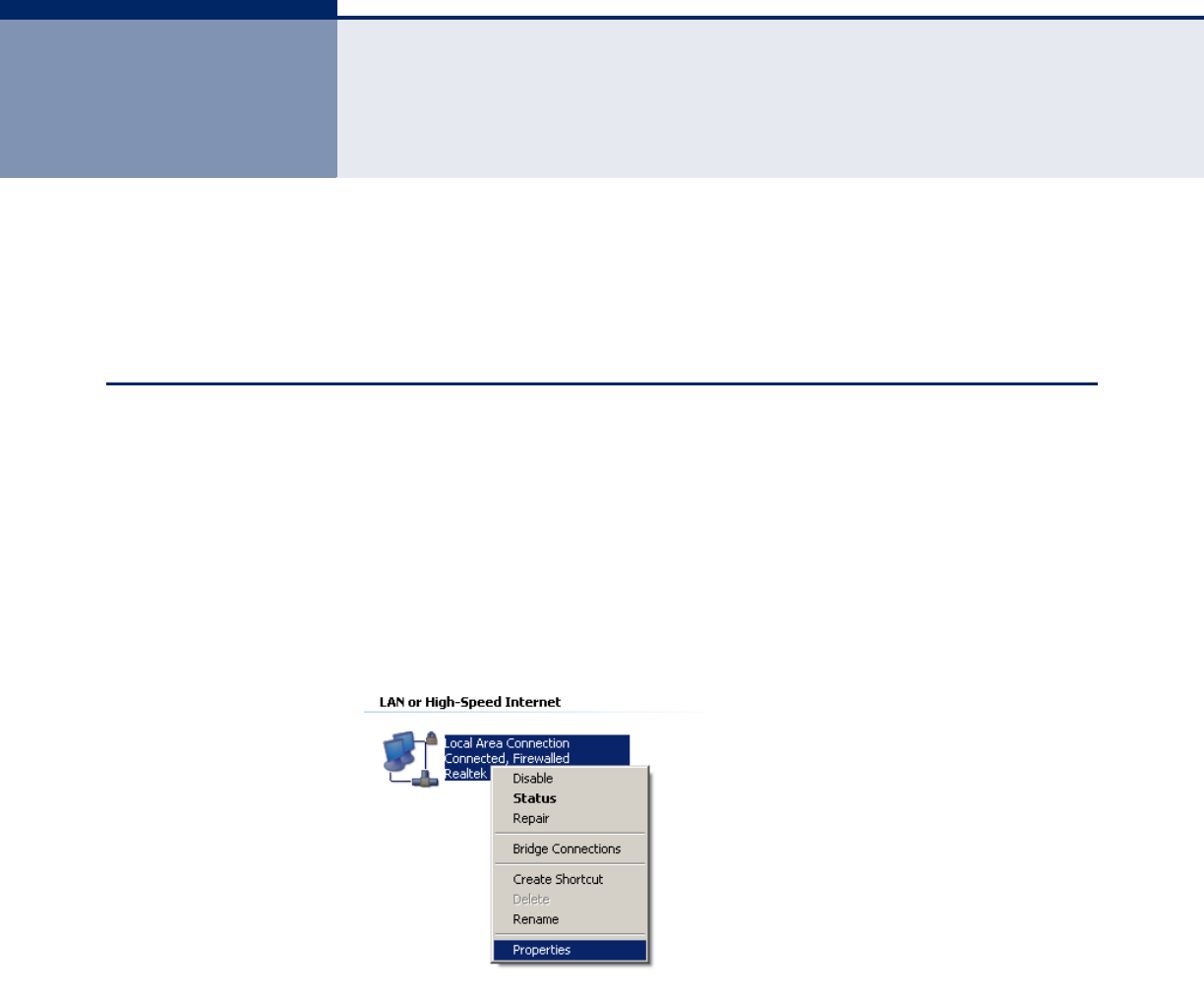
– 118 –
ACONFIGURING THE PC
The section shows how to install and configure TCP/IP settings correctly in
Windows XP. First make sure your Ethernet Adapter is working, refer to the
adapter’s manual if needed.
INSTALL TCP/IP COMPONENTS
1. On the Windows taskbar, click the Start button, point to Settings, and
then click Control Panel.
2. Click the Network and Internet Connections icon, and then click on the
Network Connections tab in the following window.
3. Right click the icon that is shown below, then select Properties from the
menu.
Figure 121: TCP/IP
4. In the window that is shown below, double click on “Internet Protocol
(TCP/IP).”
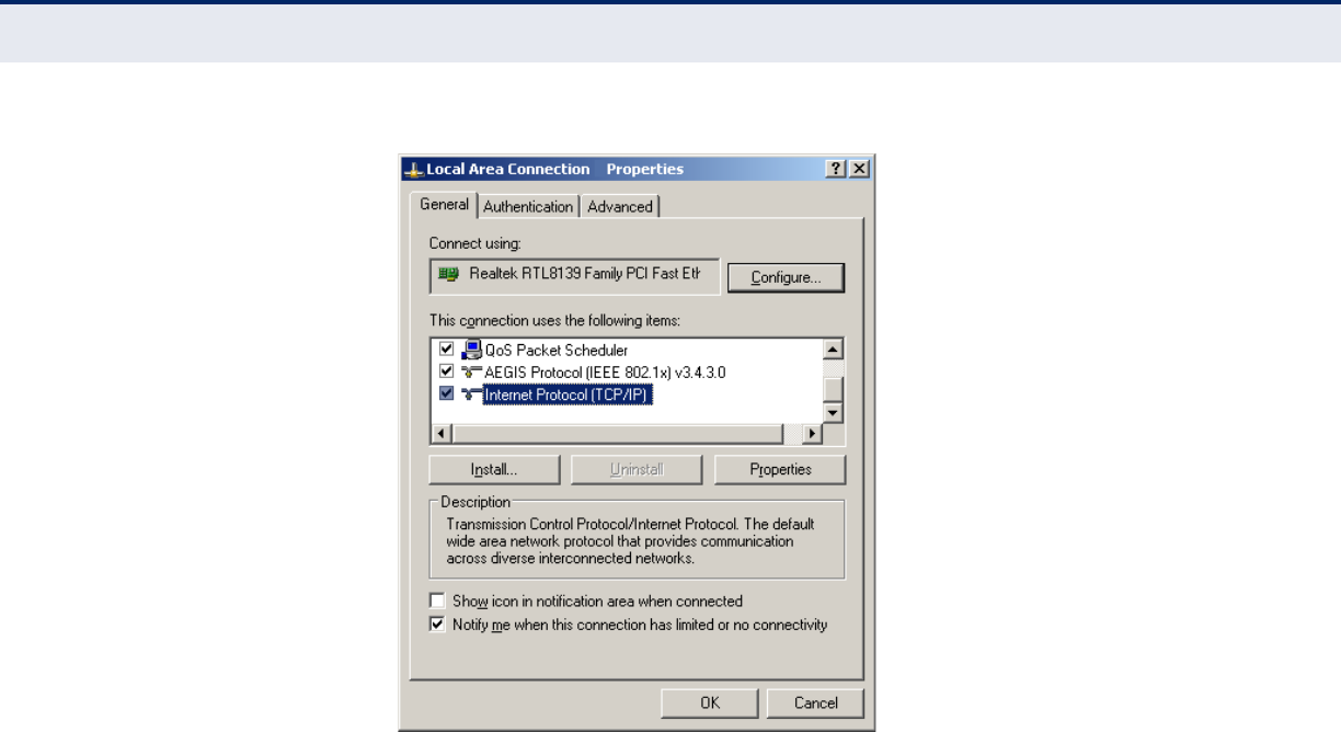
A
PPENDIX
A
| Configuring the PC
Install TCP/IP Components
– 119 –
Figure 122: Internet Protocol
5. The following TCP/IP Properties window will display and the IP Address
tab is open on this window by default.
Now you have two ways to configure the TCP/IP protocol below:
a. Set the IP address automatically.
Select “Obtain an IP address automatically,” and “Obtain DNS server
automatically,” as shown in the Figure below:
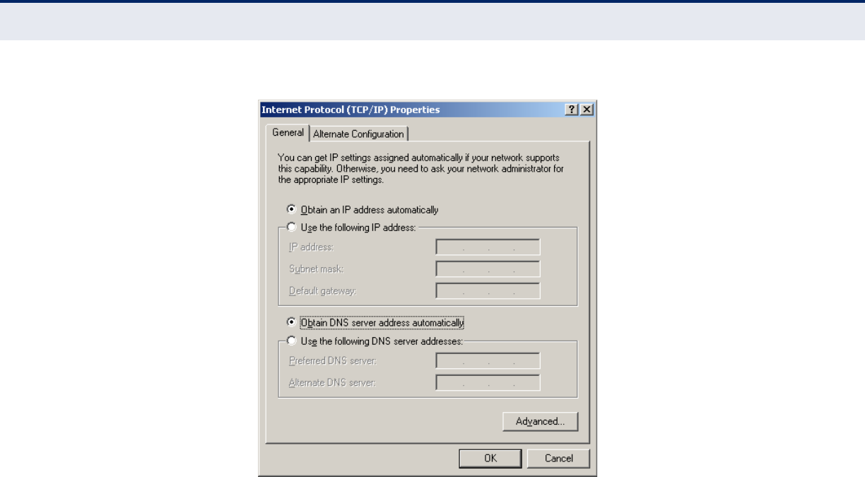
A
PPENDIX
A
| Configuring the PC
Install TCP/IP Components
– 120 –
Figure 123: Internet Protocol Properties
b. Set the IP address manually.
Select “Use the following IP address” radio button and enter the
following items:
— If the Router's LAN IP address is 192.168.2.1, type an IP
address such as 192.168.2.x (where x is from 2 to 254), and
Subnet mask as 255.255.255.0.
— Type the Router’s LAN IP address (the default IP is 192.168.2.1)
into the Default gateway field.
— Select “Use the following DNS server addresses” radio button. In
the “Preferred DNS Server” field, type the DNS server IP
address that has been provided by your ISP.
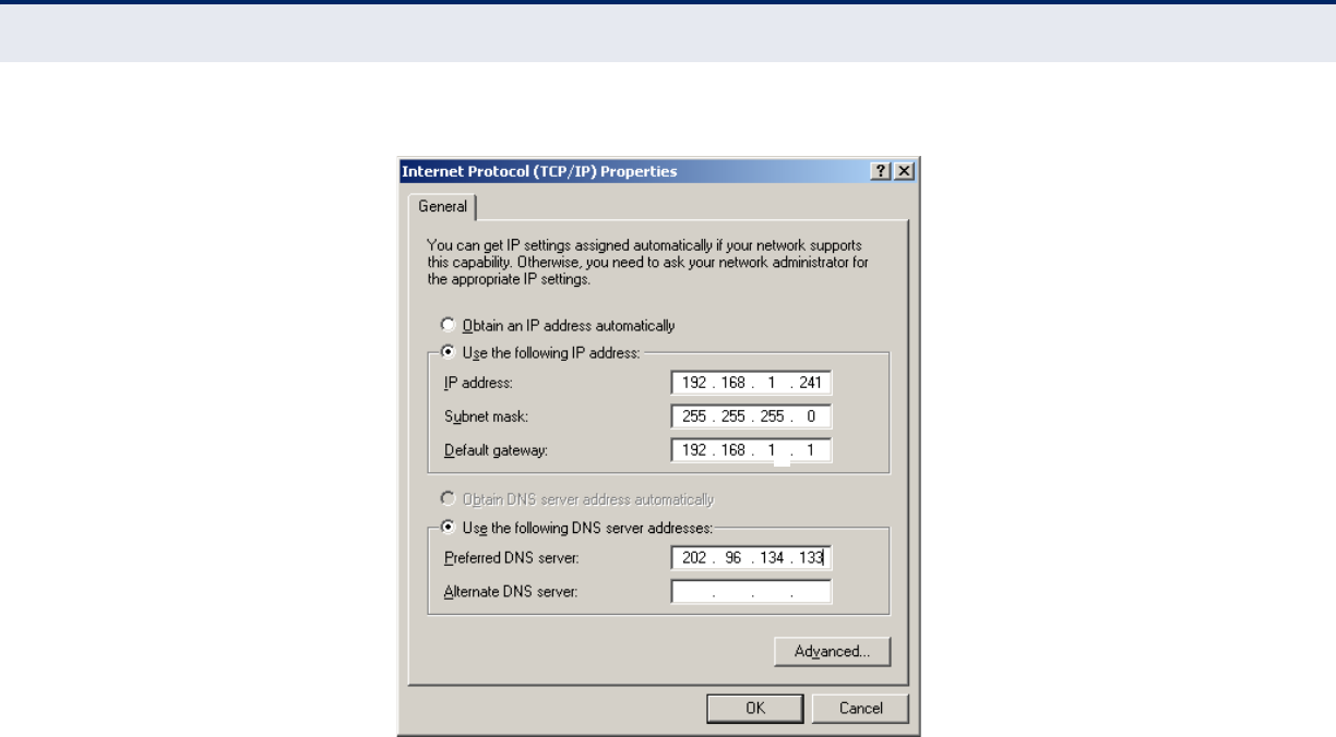
A
PPENDIX
A
| Configuring the PC
Install TCP/IP Components
– 121 –
Figure 124: Setting the IP Address Manually
6. Click OK to keep your settings.
2
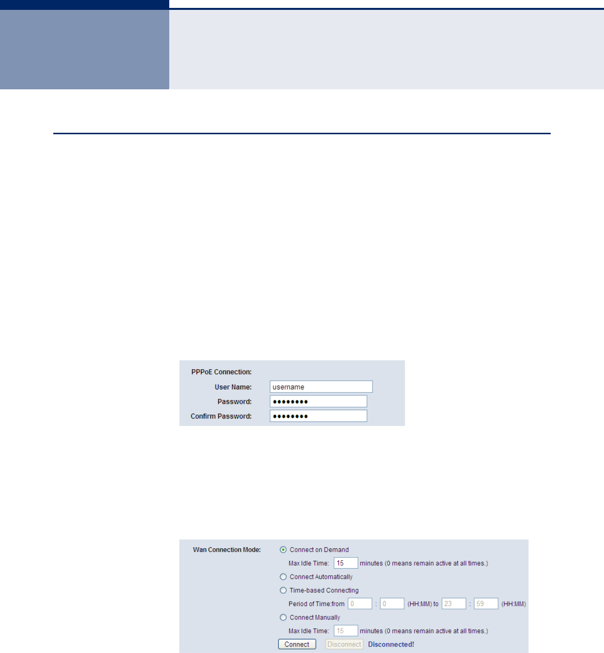
– 122 –
BFAQ
HOW DO I CONFIGURE THE ROUTER FOR INTERNET ACCESS BY ADSL USERS?
1. Configure the ADSL Modem in RFC1483 bridge mode.
2. Connect Ethernet cable from the ADSL Modem to the WAN port on the
Router. The telephone cord plugs into the Line port of the ADSL Modem.
3. Log in to the Router, click “Network” on the web page menu and then
click “WAN” on the submenu.
a. On the WAN page, select “PPPoE” for the WAN connection type.
b. Type the user name in the “User Name” field and the password in
the “Password” field.
c. Finish by clicking “Connect”.
Figure 125: PPPoE Connection Type
4. If your ADSL lease is in “pay-according-time” mode, select “Connect on
Demand,” or “Connect Manually” for Internet connection mode. Type an
appropriate value for the “Max Idle Time” to avoid wasting paid time.
Otherwise, you can select “Auto-connecting” for Internet connection
mode.
Figure 126: PPPoE Connection Mode
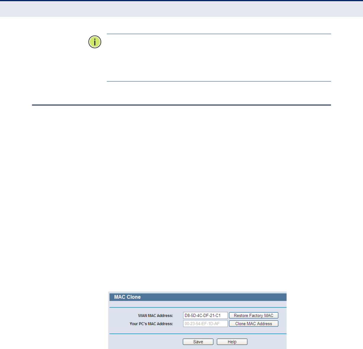
A
PPENDIX
B
| FAQ
How do I configure the Router for Internet access by Ethernet users?
– 123 –
N
OTE
:
Sometimes the connection cannot be disconnected although you
have specified a Max Idle Time, since some applications may be visiting the
Internet continually in the background.
N
OTE
:
If you are a Cable user, configure the Router following the above
steps.
HOW DO I CONFIGURE THE ROUTER FOR INTERNET ACCESS BY ETHERNET USERS?
1. Log in to the Router, click “Network” on the web page menu, and then
click "WAN" on the submenu.
a. On the WAN page, select “Dynamic IP” for the WAN connection
type.
b. Finish by clicking Save.
2. Some ISPs require that you register the MAC Address of your adapter,
which is connected to your cable/DSL Modem during installation. If
your ISP requires this, log in to the Router and click the "Network"
menu link, and then click the "MAC Clone" submenu link.
a. On the “MAC Clone” page, click the "Clone MAC Address" button if
your PC’s MAC address is a proper MAC address. Your PC’s MAC
address will fill in the “WAN MAC Address” field.
Otherwise, type the MAC Address into the “WAN MAC Address” field.
The format for the MAC Address is XX-XX-XX-XX-XX-XX.
b. Click the Save button. Settings take effect after rebooting.
Figure 127: MAC Clone
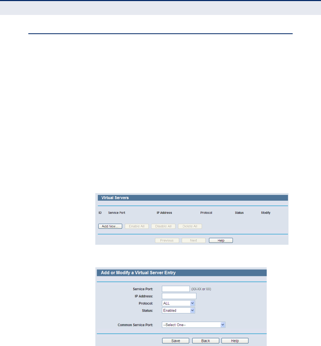
A
PPENDIX
B
| FAQ
I want to use Netmeeting, what do I need to do?
– 124 –
I WANT TO USE NETMEETING, WHAT DO I NEED TO DO?
1. If you start Netmeeting as a host, you do not need to change anything
on the Router.
2. If you start as a response, you need to configure a Virtual Server or
DMZ Host, and make sure the H323 ALG is enabled.
3. Configure a Virtual Server:
a. Log in to the Router, click “Forwarding” on the menu, and then click
"Virtual Servers" on the submenu.
b. On the “Virtual Servers” page, click “Add New”.
c. On the “Add or Modify a Virtual Server Entry” page, enter “1720” for
the “Service Port”.
d. Enter your IP address in the “IP Address” field (for example,
192.168.2.169).
e. Set to Enable and then Save.
Figure 128: Virtual Servers
Figure 129: Add or Modify a Virtual Server Entry
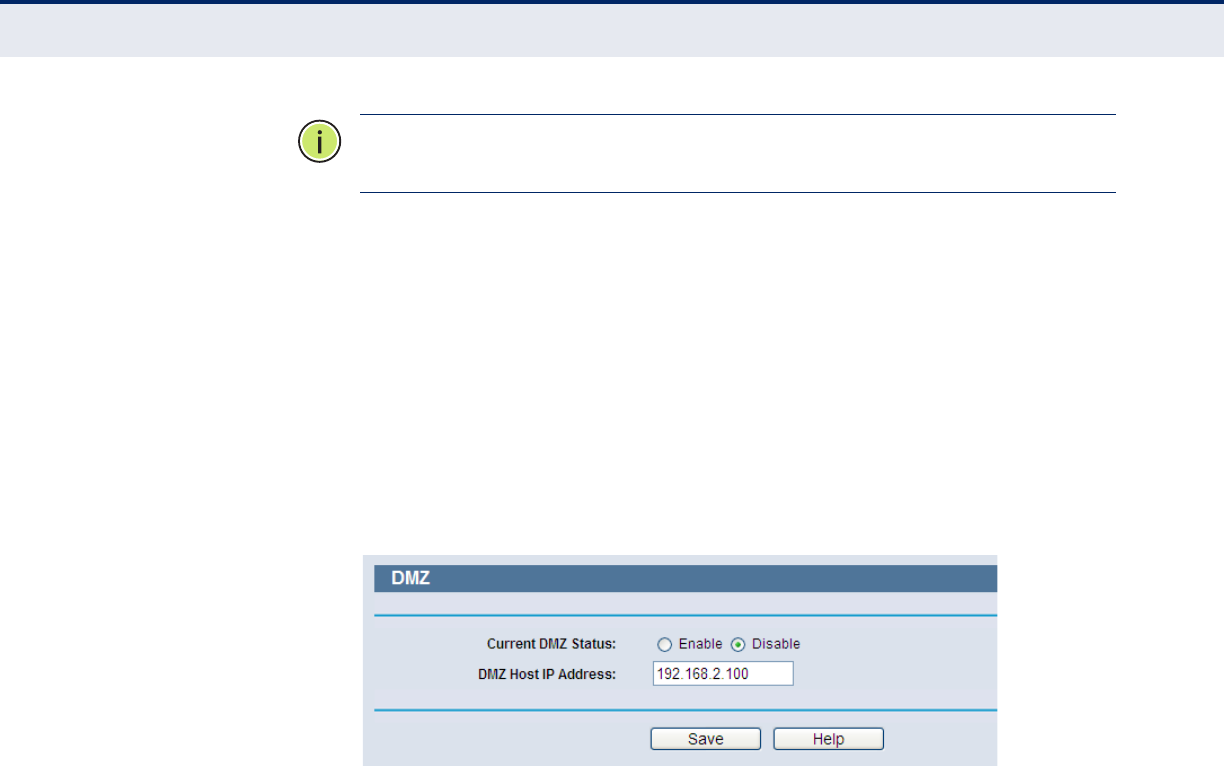
A
PPENDIX
B
| FAQ
I want to use Netmeeting, what do I need to do?
– 125 –
N
OTE
:
The other party should call your WAN IP, which is displayed on the
“Status” page.
4. Enable a DMZ Host:
a. Log in to the Router, click “Forwarding” on the menu, and then click
“DMZ” on the submenu.
b. On the "DMZ" page, click the Enable radio button.
c. Type your IP address into the “DMZ Host IP Address” field (for
example, 192.168.2.169).
d. Click the Save button.
Figure 130: DMZ
5. Enable the H323 ALG:
a. Log in to the Router, click “Security” on the menu, and then click
“Basic Security” on the submenu.
b. On the “Basic Security” page, check the Enable radio button next to
H323 ALG.
c. Click the Save button.
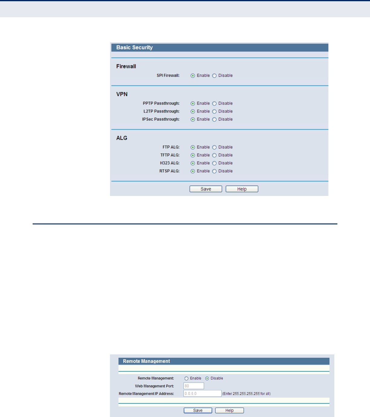
A
PPENDIX
B
| FAQ
I want to build a WEB Server on the LAN, what should I do?
– 126 –
Figure 131: Basic Security
I WANT TO BUILD A WEB SERVER ON THE LAN, WHAT SHOULD I DO?
1. Change the Web management port number:
Because the Web Server port 80 will interfere with the Web
management port 80 on the Router, you must change the Web
management port number to avoid interference.
a. Log in to the Router, click “Security” on the menu, and then click
"Remote Management" on the submenu.
b. On the "Remote Management" page, type a port number except 80,
such as 88, into the "Web Management Port" field.
c. Click Save and reboot the Router.
Figure 132: Remote Management
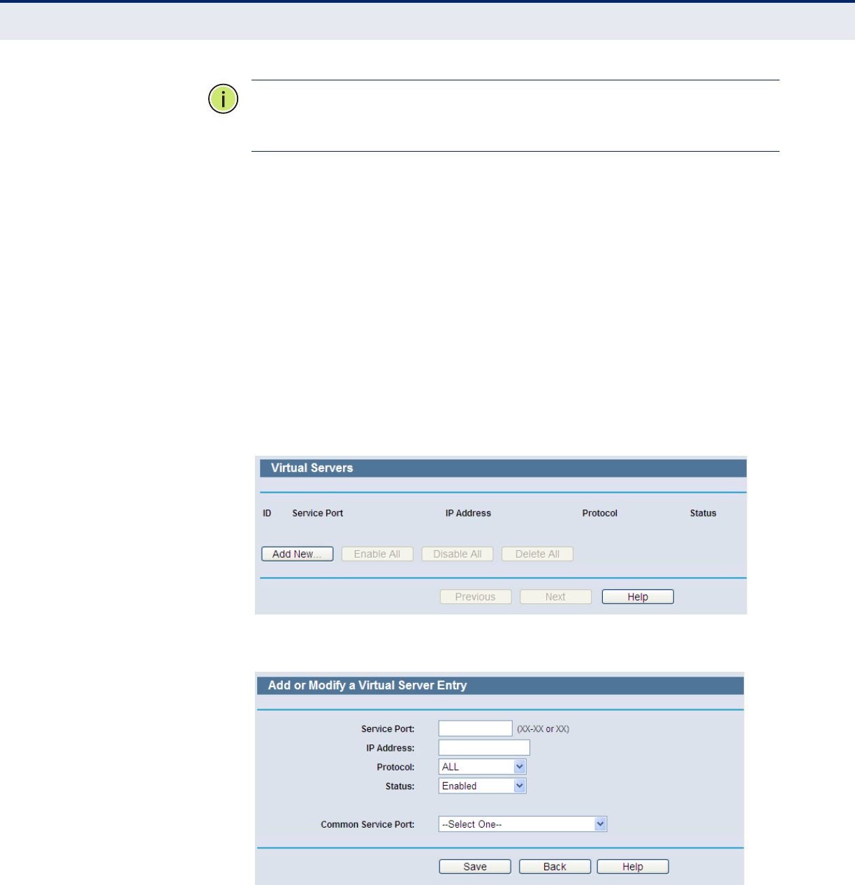
A
PPENDIX
B
| FAQ
I want to build a WEB Server on the LAN, what should I do?
– 127 –
N
OTE
:
When the above configuration takes effect, you can configure the
Router by typing “http://192.168.2.1:88” (the Router’s LAN IP address:
Web Management Port) in the address field of the Web browser.
2. Configure a Virtual Server:
a. Log in to the Router, click “Forwarding” on the menu, and then click
"Virtual Servers" on the submenu.
b. On the "Virtual Servers" page, click “Add New”.
c. On the “Add or Modify a Virtual Server” page, enter “80” into the
field for the “Service Port”.
d. Enter your IP address in the “IP Address” field (for example,
192.168.2.188).
e. Set to Enable and then Save.
Figure 133: Virtual Servers
Figure 134: Add or Modify a Virtual Server Entry

A
PPENDIX
B
| FAQ
Wireless stations cannot connect to the Router
– 128 –
WIRELESS STATIONS CANNOT CONNECT TO THE ROUTER
1. Make sure the "Wireless Router Radio" is enabled.
2. Make sure that the SSID of wireless stations is the same as the Router's
SSID.
3. Make sure wireless stations have the right encryption key for the
Router security.
4. If the wireless connection is ready, but you cannot access the Router,
check the IP Address of your wireless station.

– 129 –
CSPECIFICATIONS
STANDARDS IEEE 802.3 10BASE-T
IEEE 802.3u 100BASE-TX
802.11b
802.11g
Compatible with 802.11n
PROTOCOL TCP/IP, PPPoE, DHCP, ICMP, NAT, SNTP
PORTS One 10/100 Mbps Auto-Negotiation RJ-45 WAN port
Four 10/100 Mbps Auto-Negotiation RJ-45 LAN ports
All ports support Auto MDI/MDIX
CABLING TYPE 10BASE-T: UTP Category 3, 4, 5 cable (maximum 100 m)
EIA/TIA-568 100 STP (maximum 100 m)
100BASE-TX: UTP Category 5, 5e cable (maximum 100 m)
EIA/TIA-568 100 STP (maximum 100 m)
LED INDICATORS Power, System, WLAN, WAN, LAN (1-4), WPS
FREQUENCY BAND 2.4~2.4835 GHz
RADIO DATA RATE 11b: 11/5.5/2/1 Mbps (Automatic)
11g: 54/48/36/24/18/12/9/6 Mbps (Automatic)
11n: up to 300 Mbps (Automatic)
CHANNELS 1~13
FREQUENCY EXPANSION DSSS (Direct Sequence Spread Spectrum)
MODULATION DBPSK, DQPSK, CCK, OFDM, 16-QAM, 64-QAM

A
PPENDIX
C
| Specifications
– 130 –
SECURITY WEP/WPA/WPA2/WPA2-PSK/WPA-PSK
SENSITIVITY @PER 130 Mbps: -68dBm@10% PER
108 Mbps: -68dBm@10% PER
54 Mbps: -68dBm@10% PER
11 Mbps: -85dBm@8% PER
6 Mbps: -88dBm@10% PER
1 Mbps: -90dBm@8% PER
ANTENNA GAIN 3dBi
TEMPERATURE Operating: 0 °C to 40 °C (32 to 104 °F)
Storage: -40 °C to 70 °C (-40 to 158 °F)
HUMIDITY Operating: 10% to 90% (non-condensing)
Storge: 5%-90% (non-condensing)

– 131 –
GLOSSARY
IEEE 802.11BA wireless standard that supports wireless communications in the 2.4 GHz
band using Direct Sequence Spread Spectrum (DSSS). The standard
provides for data rates of 1, 2, 5.5, and 11 Mbps.
IEEE 802.11GA wireless standard that supports wireless communications in the 2.4 GHz
band using Orthogonal Frequency Division Multiplexing (OFDM). The
standard provides for data rates of 6, 9, 12, 18, 24, 36, 48, 54 Mbps. IEEE
802.11g is also backward compatible with IEEE 802.11b.
IEEE 802.11NA wireless standard that supports wireless communications in the 2.4 GHz
band using Orthogonal Frequency Division Multiplexing (OFDM). The
standard provides for data rates of
27, 54, 81, 108, 162, 216, 243, 270,
300
Mbps. IEEE 802.11n is also backward compatible with IEEE 802.11b/g.
DDNS (DYNAMIC
DOMAIN NAME SYSTEM)
The capability of assigning a fixed host and domain name to a dynamic
Internet IP Address.
DHCP Dynamic Host Configuration Protocol: Provides a framework for passing
configuration information to hosts on a TCP/IP network. DHCP is based on
the Bootstrap Protocol (BOOTP), adding the capability of automatic
allocation of reusable network addresses and additional configuration
options.
DMZ (DEMILITARIZED
ZONE)
A Demilitarized Zone allows one local host to be exposed to the Internet for
a special-purpose service such as Internet gaming or videoconferencing.
DNS (DOMAIN NAME
SYSTEM)
An Internet Service that translates the names of websites into IP
addresses.
DOMAIN NAME A descriptive name for an address or group of addresses on the Internet.
DSL (DIGITAL
SUBSCRIBER LINE)
A technology that allows data to be sent or received over existing
traditional phone lines.

G
LOSSARY
– 132 –
ISP (INTERNET SERVICE
PROVIDER)
A company that provides access to the Internet.
MTU (MAXIMUM
TRANSMISSION UNIT)
The size in bytes of the largest packet that can be transmitted.
NAT (NETWORK
ADDRESS TRANSLATION)
NAT technology translates IP addresses of a local area network to a
different IP address for the Internet.
PPPOE (POINT TO POINT
PROTOCOL OVER
ETHERNET)
PPPoE is a protocol for connecting remote hosts to the Internet over an
always-on connection by simulating a dial-up connection.
SSID A Service Set Identification is a thirty-two character (maximum)
alphanumeric key identifying a wireless local area network. For the wireless
devices in a network to communicate with each other, all devices must be
configured with the same SSID. This is typically the configuration
parameter for a wireless PC card. It corresponds to the ESSID in the
wireless Access Point and to the wireless network name.
WEP (WIRED
EQUIVALENT PRIVACY)
A data privacy mechanism based on a 64-bit, 128-bit, or 152-bit shared-
key algorithm, as described in the IEEE 802.11 standard.
WI-FIA trade name for the 802.11b wireless networking standard, given by the
Wireless Ethernet Compatibility Alliance (WECA, see http://www.wi-fi.net),
an industry standards group promoting interoperability among 802.11b
devices.
WLAN (WIRELESS
LOCAL AREA NETWORK)
A group of computers and associated devices communicate with each other
wirelessly, which network serving users are limited in a local area.

– 133 –
INDEX
A
AC power adapter 23
antennas 21
B
basic setup, wizard 34
BigPond Cable settings 46
buttons
Reset 21
C
channel, operating 29
connections, router 22
contents of package 19
D
DDNS 53
default IP 24
diagnostic tools 107
DNS addresses 43
Dynamic IP 27, 45
E
environment requirements 22
Ethernet port 21
F
factory defaults, setting 109
feature overview 17
features, hardware 19
firmware upgrade 108
H
hardware features 19
humidity, operating 22
I
indicators
WPS 20
information, status 33
installation environment 22
IP configuration 24
ISP setup 27
K
key features 19
L
LAN LED 20
LAN ports 21
LED indicators 20
LEDs
LAN 20
Power 20
System 20
WAN 20
WLAN 20
WPS 20
local management 116
location of router 22
logging in, web 26
login page 32
login password 28
logs, system 112
M
MAC Address, WAN 52
MAC Clone 51
main menu 32
Max Idle Time 45
menu, main 32
MTU size 43
N
network connections, checking 24
network settings 42
O
overview 17
P
package contents 19
password 28
password, setting 111
PBC, WPS 35
PC connections 22

I
NDEX
– 134 –
PIN, WPS 34
Ping, using 24
power adapter 23
power connector 21
Power LED 20
PPPoE 27
proxy, web setting 27
push button, WPS 35
Q
quick setup 27
R
radio channel 29
radio enable 29
region setting,country setting 29
remote management 117
requirements, system 22
Reset button 21
reset button 21
router status 33
S
setup wizard steps 34
setup, quick 27
SMTP server 113
software upgrade 108
specifications, hardware 129
Static IP 27, 45
statistics 114
status information 33
System LED 20
system logs 112
system requirements 22
T
TCP/IP configuration 24
TCP/IP settings 118
temperature, operating 22
U
upgrading software 108
user name, setting 28
utility, login 26
W
WAN LED 20
WAN port 21
WAN settings 42
WAN setup 27
web login 26, 32
web menu 32
Wi-Fi Protected Setup 34
wireless security 30
wireless, enable 29
wizard, setup 24, 34
WLAN LED 20
WPS 34
WPS LED 20
Middle East Office
Office No. 416, Le Solarium Bldg
Dubai Silicon Oasis
Dubai, U.A.E.
Tel: +971-4-3564800
Fax:+971-4-3564801
Europe & N. Africa Office
C/Fructuós Gelabert 6-8, 2o, 2a
Edificio Conata II
08970 Sant Joan Despí
Barcelona, Spain
Tel: +34 93 477 4920
Asia-Pacific Office
1 Coleman Street
#07-09, The Adelphi
Singapore 179803
Tel: +65-63387667
Fax: +65-63387767
(for Asia-Pacific): Technical Support information at www.smc-asia.com
Headquarters &
Sub-Sahara Africa Office
No. 1, Creation Rd. III
Hsinchu Science Park
Taiwan 30077
Tel: +886 3 5770270
Fax: +886 3 5780764
North America Office
20 Mason
Irvine CA 92618 U.S.A.
Tel: +1 (949) 679-8000
SMC NETWORKS TECHNICAL SUPPORT
From U.S.A. and Canada (24 hours a day, 7 days a week)
Tel: +1 (800) SMC-4-YOU/+1 (949) 679-8000 Fax: +1 (949) 679-1481
www.smcnetworks.co.kr
From Singapore in English and (Mon.-Fri. 9 AM to 5 PM)
Tel: +65-63387667, Ext. 4
From the United Arab Emirates in English (Sun.-Thu. 9 AM to 6 PM)
Tel: +971 800 222866/+971 4 3564810
(for Middle East): Technical Support information at muneer@smc-asia.com
www.edge-core.com / www.smc.com
SMCWGBR14-N2
Middle East Office
Office No. 416, Le Solarium Bldg
Dubai Silicon Oasis
Dubai, U.A.E.
Tel: +971-4-3564800
Fax:+971-4-3564801
Europe & N. Africa Office
C/Fructuós Gelabert 6-8, 2o, 2a
Edificio Conata II
08970 Sant Joan Despí
Barcelona, Spain
Tel: +34 93 477 4920
Asia-Pacific Office
1 Coleman Street
#07-09, The Adelphi
Singapore 179803
Tel: +65-63387667
Fax: +65-63387767
(for Asia-Pacific): Technical Support information at www.smc-asia.com
Headquarters &
Sub-Sahara Africa Office
No. 1, Creation Rd. III
Hsinchu Science Park
Taiwan 30077
Tel: +886 3 5770270
Fax: +886 3 5780764
North America Office
20 Mason
Irvine CA 92618 U.S.A.
Tel: +1 (949) 679-8000
SMC NETWORKS TECHNICAL SUPPORT
From U.S.A. and Canada (24 hours a day, 7 days a week)
Tel: +1 (800) SMC-4-YOU/+1 (949) 679-8000 Fax: +1 (949) 679-1481
www.smcnetworks.co.kr
From Singapore in English and (Mon.-Fri. 9 AM to 5 PM)
Tel: +65-63387667, Ext. 4
From the United Arab Emirates in English (Sun.-Thu. 9 AM to 6 PM)
Tel: +971 800 222866/+971 4 3564810
(for Middle East): Technical Support information at muneer@smc-asia.com
www.edge-core.com / www.smc.com
SMCWBR14S-N5, SMCWBR14-N5