Edgecore Networks SMCWBR14SN5V2 150 Mbps 4-Port Wireless Broadband Router User Manual user guide
Edgecore Networks Corporation 150 Mbps 4-Port Wireless Broadband Router user guide
UserManual.wiki
>
Edgecore Networks
>
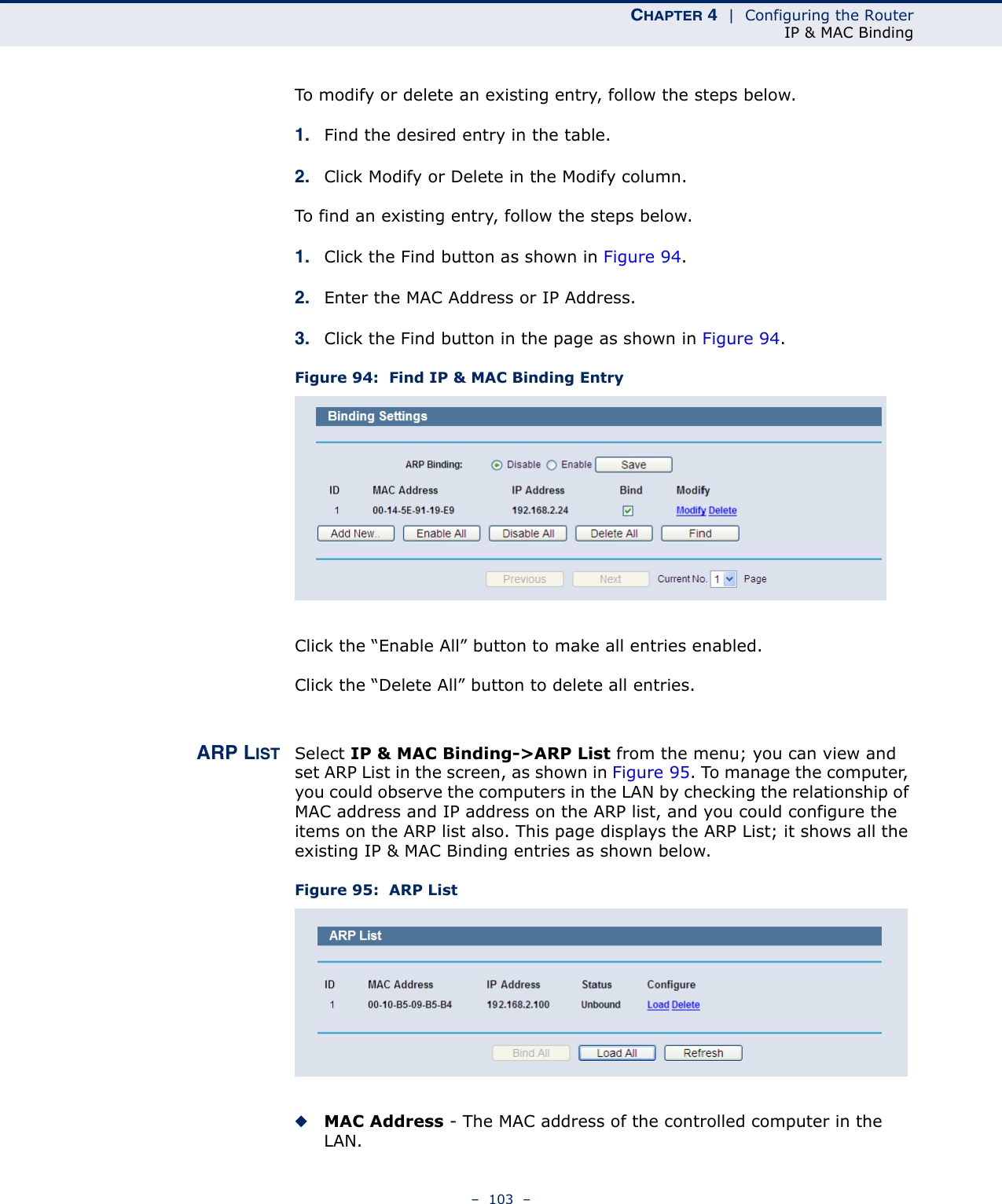
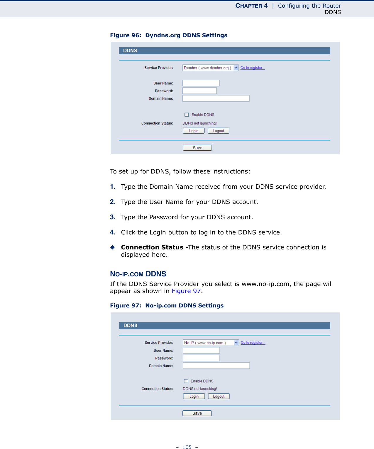
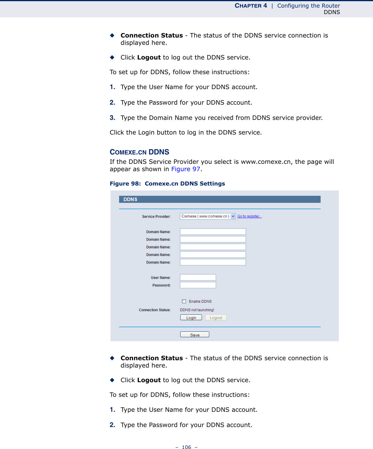
SMCWBR14SN5V2 User Manual
User Manual
Navigation menu
Upload a User Manual
Namespaces
Wiki Guide
HTML
PDF
Info
Views
User Manual
Discussion / Help
Navigation