Edgecore Networks SMCWGBR14N2 802.11n Wireless 4-port Gigabit Broadband Router User Manual user guide
Edgecore Networks Corporation 802.11n Wireless 4-port Gigabit Broadband Router user guide
Contents
- 1. User Manual 1
- 2. User Manual 2
User Manual 1

USER GUIDE
BARRICADETM N
802.11n Wireless 4-port Gigabit Broadband Router
SMCWGBR14-N2

Barricade
TM
N SMCWGBR14-N2
User Guide
May 2011
SMC-UG-0511-01
No. 1, Creation Road III,
Hsinchu Science Park,
30077, Taiwan, R.O.C.
TEL: +886 3 5770270
Fax: +886 3 5780764
Information furnished by SMC Networks, Inc. (SMC) is believed to be accurate and reliable.
However, no responsibility is assumed by SMC for its use, nor for any infringements of patents or
other rights of third parties which may result from its use. No license is granted by implication or
otherwise under any patent or patent rights of SMC. SMC reserves the right to change specifications
at any time without notice.
Copyright © 2011 by
SMC Networks, Inc.
No. 1 Creation Road III,
Hsinchu Science Park,
30077, Taiwan, R.O.C.
All rights reserved
Trademarks:
SMC is a registered trademark; and Barricade, EZ Switch, TigerStack, TigerSwitch, and TigerAccess
are trademarks of SMC Networks, Inc. Other product and company names are trademarks or
registered trademarks of their respective holders.
– 4 –
WARRANTY AND PRODUCT REGISTRATION
To register SMC products and to review the detailed warranty statement,
please refer to the Support Section of the SMC Website at http://
www.smc.com.

– 5 –
COMPLIANCES
FEDERAL COMMUNICATION COMMISSION INTERFERENCE STATEMENT
This equipment has been tested and found to comply with the limits for a
Class B digital device, pursuant to part 15 of the FCC Rules. These limits
are designed to provide reasonable protection against harmful interference
in a residential installation. This equipment generates, uses and can
radiate radio frequency energy and, if not installed and used in accordance
with the instructions, may cause harmful interference to radio
communications. However, there is no guarantee that interference will not
occur in a particular installation. If this equipment does cause harmful
interference to radio or television reception, which can be determined by
turning the equipment off and on, the user is encouraged to try to correct
the interference by one or more of the following measures:
◆Reorient or relocate the receiving antenna
◆Increase the separation between the equipment and receiver
◆Connect the equipment into an outlet on a circuit different from that to
which the receiver is connected
◆Consult the dealer or an experienced radio/TV technician for help
This device complies with Part 15 of the FCC Rules. Operation is subject to
the following two conditions: (1) This device may not cause harmful
interference, and (2) this device must accept any interference received,
including interference that may cause undesired operation.
FCC Caution: Any changes or modifications not expressly approved by the
party responsible for compliance could void the user's authority to operate
this equipment.
N
OTE
:
The manufacturer is not responsible for any radio or tv interference
caused by unauthorized modifications to this equipment. Such
modifications could void the user’s authority to operate the equipment.
C
OMPLIANCES
– 6 –
IMPORTANT NOTE:
FCC RADIATION EXPOSURE STATEMENT
This equipment complies with FCC RF radiation exposure limits set forth for
an uncontrolled environment. This device and its antenna must not be co-
located or operating in conjunction with any other antenna or transmitter.
To comply with FCC RF exposure compliance requirements, this grant is
applicable to only Mobile Configurations. The antennas used for this
transmitter must be installed to provide a separation distance of at least 20
cm from all persons and must not be co-located or operating in conjunction
with any other antenna or transmitter.
CE MARK WARNING
This is a class B product. In a domestic environment, this product may
cause radio interference, in which case the user may be required to take
adequate measures.
NATIONAL RESTRICTIONS
This device is intended for home and office use in all EU countries (and
other countries following the EU directive 1999/5/EC) without any
limitation except for the countries mentioned below.
N
OTE
:
Do not use the product outdoors in France.
Country Restriction Reason/Remark
Bulgaria None General authorization required for outdoor use and
public service
France Outdoor use
limited to 10 mW
e.i.r.p. within the
band 2454-2483.5
MHz
Military Radiolocation use. Refarming of the 2.4 GHz
band has been ongoing in recent years to allow
current relaxed regulation. Full implementation
planned 2012
italy None If used outside of own premises, general
authorization is required
Luxembourg None General authorization required for network and
service supply(not for spectrum)
Norway Implemented This subsection does not apply for the geographical
area within a radius of 20 km from the centre of Ny-
Ålesund
Russian
Federation None Only for indoor applications
– 7 –
ABOUT THIS GUIDE
PURPOSE This guide details the hardware features of the wireless router, including its
physical and performance-related characteristics, and how to install the
device and use its configuration software.
AUDIENCE This guide is for PC users with a working knowledge of computers. You
should be familiar with Windows operating system concepts.
CONVENTIONS The following conventions are used throughout this guide to show
information:
N
OTE
:
Emphasizes important information or calls your attention to related
features or instructions.
C
AUTION
:
Alerts you to a potential hazard that could cause loss of data, or
damage the system or equipment.
W
ARNING
:
Alerts you to a potential hazard that could cause personal injury.
RELATED PUBLICATIONS The following publication gives basic information on how to install and use
the wireless router.
Quick Installation Guide
Also, as part of the wireless router’s software, there is online help that
describes all configuration related features.
REVISION HISTORY This section summarizes the changes in each revision of this guide.
MAY 2011 REVISION
This is the first revision of this guide.

– 8 –
CONTENTS
WARRANTY AND PRODUCT REGISTRATION 4
COMPLIANCES 5
ABOUT THIS GUIDE 7
CONTENTS 8
1I
NTRODUCTION 11
Conventions 12
Main Features 12
Key Hardware Features 13
Package Contents 13
Front Panel 13
LED Indicators 14
Rear Panel 15
Antennas 15
Power Connector 15
Reset Button 15
USB Port 15
Ethernet WAN Port 16
Ethernet LAN Port 16
2CONNECTING THE ROUTER 17
System Requirements 17
Installation Environment Requirements 17
Connecting the Router 18
3QUICK INSTALLATION GUIDE 20
TCP/IP Configuration 20
Quick Installation Guide 22
4CONFIGURING THE ROUTER 28
Login 28
Status 29

C
ONTENTS
– 9 –
General Status 29
ARP List 29
Quick Setup 30
5NETWORK SETTINGS 31
WAN 31
MAC Clone 40
LAN 41
Dynamic DNS 41
Comexe.cn DDNS 42
Dyndns.org DDNS 43
No-ip.com DDNS 44
Binding Setting 44
6WIRELESS SETTINGS 47
Wireless Settings 47
Wireless Security 49
Wireless MAC Filtering 53
Wireless Advanced 55
Wireless Statistics 57
WPS 57
7 DHCP SETTINGS 65
DHCP Settings 65
DHCP Clients List 66
Address Reservation 67
8USB STORAGE SETTINGS 69
Sharing Service 69
User Accounts 71
9SPECIAL APPLICATION SETTINGS 73
Virtual Servers 73
Port Triggering 75
DMZ 77
UPnP 78
10 SECURITY SETTINGS 79
Basic Security 79
Advanced Security 81

C
ONTENTS
– 10 –
11 ACCESS CONTROL SETTINGS 83
Rule 83
Host 86
Target 88
Schedule 90
Parental Control 92
12 ADVANCED ROUTING 96
Static Routing List 96
13 QOS SETTINGS 98
QoS Settings 98
Rules List 99
14 SYSTEM TOOLS 101
Time Setting 101
Diagnostic 102
Settings Management 104
Firmware Upgrade 104
Factory Defaults 105
Backup & Restore 105
Reboot 106
Password 107
System Log 108
Statistics 110
Local Management 111
Remote Management 112
AFAQ 114
BC
ONFIGURING THE PCS 119
CH
ARDWARE SPECIFICATIONS 122
GLOSSARY 124

– 11 –
1INTRODUCTION
The SMCWGBR14-N2 Wireless N Gigabit Router integrates a 4-port switch,
firewall, NAT router, and wireless access point. The Wireless N Gigabit
Router delivers exceptional range and speed, which can fully meet the
needs of Small Office/Home Office (SOHO) networks and users demanding
higher networking performance.
INCREDIBLE SPEED
The SMCWGBR14-N2 Wireless N Gigabit Router provides wireless
connections up to 300 Mbps with other 802.11n wireless clients. The
incredible speed makes it ideal for handling multiple data streams at the
same time, which ensures your network remains stable and smooth. The
performance of this 802.11n wireless router gives you an unexpected
networking experience at a speed 650% faster than 802.11g. It is also
compatible with all IEEE 802.11g and IEEE 802.11b products.
MULTIPLE SECURITY PROTECTION
With multiple protection measures, including SSID broadcast control, 64/
128/152-bit WEP encryption, Wi-Fi Protected Access (WPA2-PSK, WPA-
PSK), as well as advanced firewall protection, the SMCWGBR14-N2
Wireless N Gigabit Router provides complete data privacy.
FLEXIBLE ACCESS CONTROL
The SMCWGBR14-N2 Wireless N Gigabit Router provides flexible access
control, so that parents or network administrators can establish restricted
access policies for children or staff. It also supports Virtual Server and DMZ
host for Port Triggering, so that network administrators can manage and
monitor the network in real time using remote management.
SIMPLE INSTALLATION
Since the SMCWGBR14-N2 is compatible with all major operating systems,
it is very easy to manage. A Quick Setup Wizard is supported and detailed
step-by-step instructions are provided in this user guide. Before installing
the device, please read this guide to understand all the device’s functions.

C
HAPTER
1
| Introduction
Conventions
– 12 –
CONVENTIONS
The “Router” or “SMCWGBR14-N2” mentioned in this guide stands for the
SMCWGBR14-N2 Wireless N Gigabit Router without any explanation.
MAIN FEATURES
◆Complies with IEEE 802.11n to provide a wireless data rate of up to
300 Mbps.
◆One 10/100/1000 Mbps Auto-Negotiation RJ-45 WAN port, four 10/
100/1000 Mbps Auto-Negotiation RJ-45 LAN ports, supporting Auto
MDI/MDIX
◆Provides WPA/WPA2, WPA-PSK/WPA2-PSK authentication, TKIP/AES
encryption security.
◆Shares data and Internet access for users, supporting Dynamic IP/
Static IP/PPPoE Internet access.
◆Supports multiple SSIDs, which allows different network access for
wireless clients that is appropriate to their security or needs.
◆Supports Virtual Server, Special Application and DMZ host.
◆Supports UPnP, Dynamic DNS, Static Routing.
◆Provides automatic and scheduled Internet connection.
◆Built-in NAT and DHCP server supporting static IP address assignment.
◆Supports Parental Control and Access Control.
◆Supports PPPoE Internet-on-demand connection/disconnection
◆Provides 64/128/152-bit WEP encryption security and wireless LAN ACL
(Access Control List).
◆Supports Flow Statistics.
◆Supports firmware upgrade and Web management.
C
HAPTER
1
| Introduction
Key Hardware Features
– 13 –
KEY HARDWARE FEATURES
The following table describes the main hardware features of the wireless
Router.
PACKAGE CONTENTS
The Wireless N Gigabit Router package includes:
◆
SMCWGBR14-N2 Wireless N Gigabit Router
◆DC power adapter
◆Quick Installation Guide
◆Resource CD for SMCWGBR14-N2 Wireless N Gigabit Router, including:
■This User Guide
■Other helpful information
Inform your dealer if there are any incorrect, missing or damaged parts. If
possible, retain the carton, including the original packing materials. Use
them again to repack the product in case there is a need to return it.
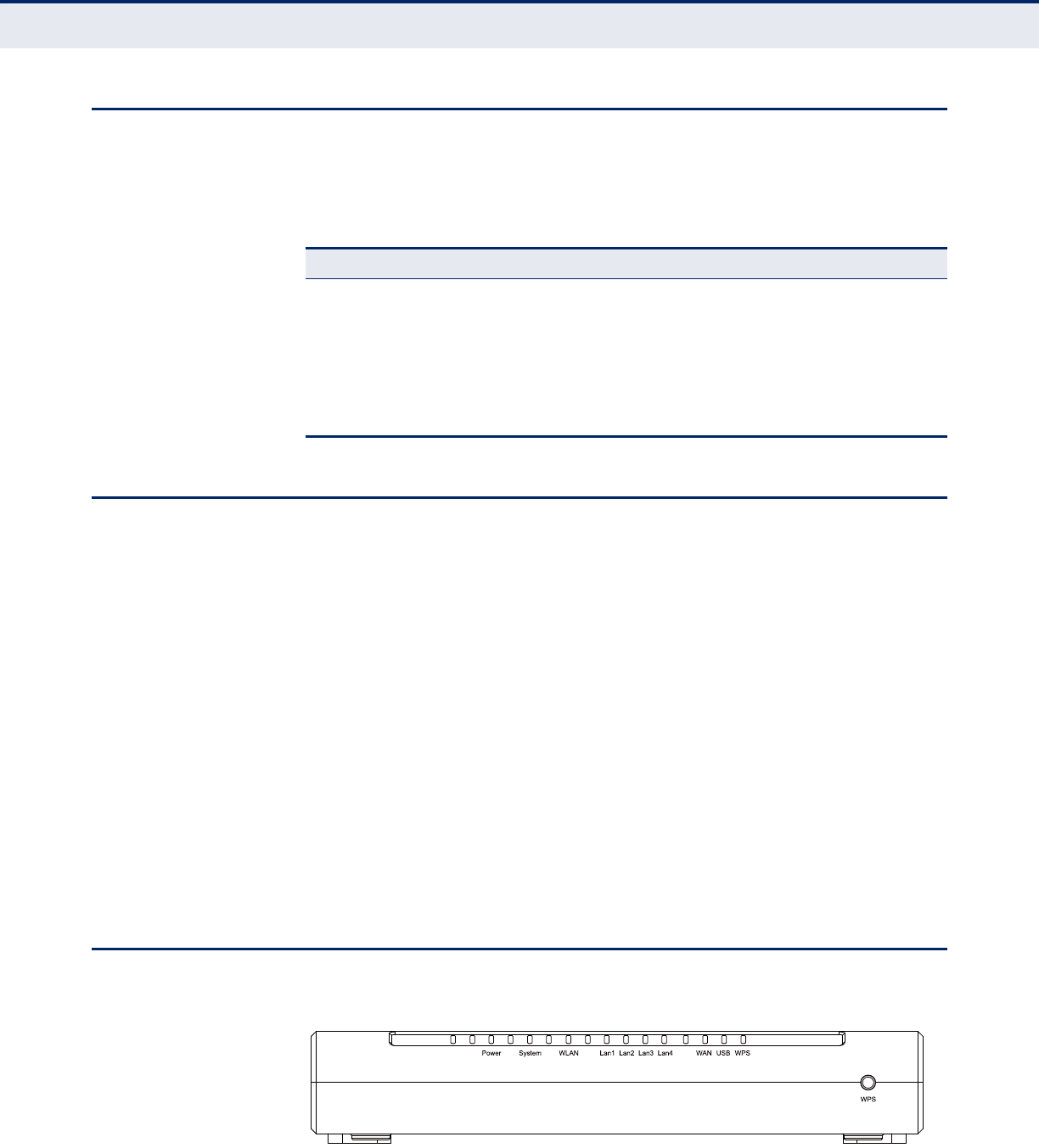
FRONT PANEL
Figure 1: Front Panel
Table 1: Key Hardware Features
Feature Description
WAN Port One 1000BASE-T RJ-45 port for connecting to the Internet.
LAN Port Four 1000BASE-T RJ-45 ports for local network connections.
USB Port One USB slot for USB mass storage device.
Reset Button For resetting the unit and restoring factory defaults.
LEDs Provides LED indicators for Power, WAN port, LAN port, and WLAN
status.

C
HAPTER
1
| Introduction
Front Panel
– 14 –
LED INDICATORS The
wireless Router
includes ten status LED indicators, as described in the
following table.
N
OTE
:
After a device is successfully added to the network by WPS, the WPS
LED will remain on for about 5 minutes and then turn off.
Table 2: LED Behavior
LED Status Description
Power On The unit is receiving power and is operating normally.
Off There is no power currently being supplied to the
unit.
System On The Router is initializing.
Flashing The Router is working properly.
Off The Router has a system error.
WLAN On/Flashing The 802.11n radio is enabled and
transmitting or receiving data through wireless links.
Off The 802.11n radio is disabled.
LAN (4 LEDs) On The Ethernet LAN port is connected to a PC or server.
Flashing The Ethernet port is connected and is transmitting or
receiving data.
Off The Ethernet port is disconnected.
WAN On The port has a valid connection to another device.
Flashing The port is connected and is transmitting/receiving
data.
Off The port is disconnected.
WPS On Indicates the WPS authentication of a device has
been successfully completed.
Fast Flashing A wireless device failed to be added to the network by
WPS.
Slow Flashing A wireless device is connecting to the network by
WPS. This process will last for 2 minutes.
Off The WPS is not in progress.
C
HAPTER
1
| Introduction
Rear Panel
– 15 –
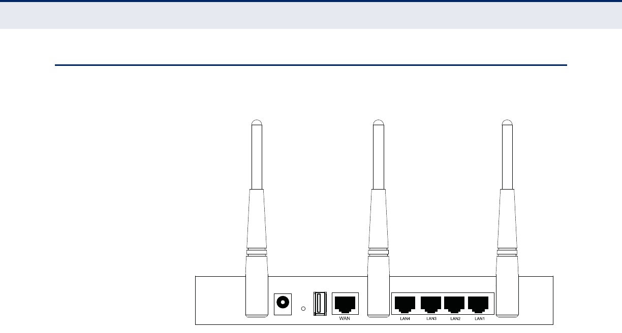
REAR PANEL
Figure 2: Rear Panel
The following items are located on the rear panel (from left to right).
ANTENNAS The access point includes integrated MIMO antennas for wireless
communications. A MIMO antenna system uses two or more identical
antennas to receive and transmit signals, helping to increase data
throughput and range. The antennas transmit the outgoing signal as a
toroidal sphere (doughnut shaped), with the coverage extending most in a
direction perpendicular to the antenna. The antennas should be adjusted to
an angle that provides the appropriate coverage for the service area.
POWER CONNECTOR The wireless router must be powered with its supplied power adapter.
Failure to do so results in voiding of any warrantly supplied with the
product.
RESET BUTTON The Reset button is used to restore the factory default configuration. If you
hold down the button for 5 seconds or more, any configuration changes
you may have made are removed, and the factory default configuration is
restored to the wireless router.
USB PORT Connects with a USB mass storage device.
POWER RESET USB

C
HAPTER
1
| Introduction
Rear Panel
– 16 –
ETHERNET WAN PORT A 1000BASE-T RJ-45 port that can be attached to an Internet access
device, such as a DSL or Cable modem.
ETHERNET LAN PORT The wireless router has four 1000BASE-T RJ-45 ports that can be attached
directly to a PC or 10BASE-T/100BASE-TX/1000BASE-T LAN segments.
This port supports automatic MDI/MDI-X operation, so you can use
straight-through cables for all network connections to PCs, switches, or
hubs.

– 17 –
2CONNECTING THE ROUTER
SYSTEM REQUIREMENTS
You must meet the following minimum requirements:
◆Broadband Internet access service (DSL/Cable/Ethernet)
◆One DSL/Cable modem that has an RJ-45 connector
◆PCs with working Ethernet adapters and Ethernet cables with RJ-45
connectors
◆TCP/IP protocol on each PC
◆Web browser, such as Internet Explorer 5.5 or above, Netscape 4.7
or above, Mozilla Firefox 1.0 or above
INSTALLATION ENVIRONMENT REQUIREMENTS
◆Place the Router in a well ventilated place far from any heater or
heating vent
◆Avoid direct irradiation from any strong light (such as sunlight)
◆Keep at least 2 inches (5 cm) of clear space around the Router
◆Operating Temperature: 0°C~40°C (32°F~104°F)
◆Operating Humidity: 10%~90%RH, Non-condensing

C
HAPTER
2
| Connecting the Router
Connecting the Router
– 18 –
CONNECTING THE ROUTER
Before installing the Router, make sure your PC is successfully connected to
the Internet through the broadband service. If there is any problem, first
contact your ISP.
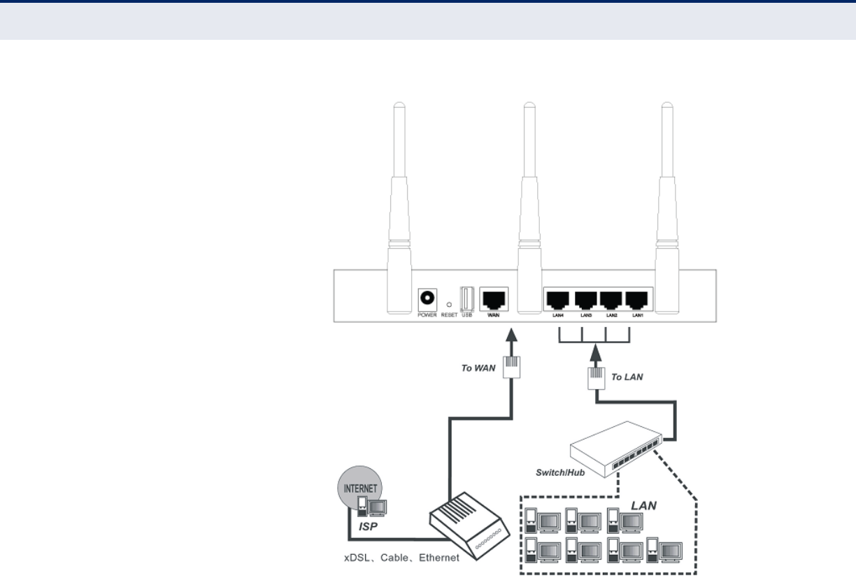
Install the Router according to the following steps.
1. Power off your PC, Cable/DSL modem, and the Router.
2. Find a good location for the Router. The best place is usually at the
center of your network. The location must meet the Installation
Environment Requirements (page 17).
3. Adjust the position of the antennas. Normally, upright is the best
position.
4. Connect wired PCs and switches/hubs to the LAN ports on the Router,
as shown in Figure 3 on page 19.
5. Connect the DSL/Cable modem to the WAN port on the Router, as
shown in Figure 3 on page 19.
6. Connect the power adapter to the power socket on the Router, and the
other end into an electrical outlet. The Router will start to work
automatically.
7. Power on your PC and Cable/DSL modem.
C
HAPTER
2
| Connecting the Router
Connecting the Router
– 19 –
Figure 3: Hardware Installation

– 20 –
3QUICK INSTALLATION GUIDE
TCP/IP CONFIGURATION
This chapter shows you how to quickly configure the basic functions of your
SMCWGBR14-N2 Wireless N Gigabit Router using the Quick Setup Wizard.
The default IP address of the SMCWGBR14-N2 Wireless N Gigabit Router is
192.168.2.1. And the default Subnet Mask is 255.255.255.0. These values
can be changed as needed. In this guide, the default values are used for all
descriptions.
Connect a local PC to one of the LAN ports on the Router. Then configure
the IP address for the PC in one of the following two ways.
Configure the IP address manually
1. Set up the TCP/IP Protocol for your PC. If you need instructions on how
to do this, refer to “Configuring the PCs” on page 119.
2. Configure the network parameters. The IP address is 192.168.2.xxx
(“xxx” is any number from 2 to 254), the Subnet Mask is
255.255.255.0, and the Gateway is 192.168.2.1 (the Router's default
IP address).
Obtain an IP address automatically
1. Set the TCP/IP Protocol to “Obtain an IP address automatically” mode
on your PC. If you need instructions on how to do this, refer to
“Configuring the PCs” on page 119.
2. The built-in DHCP server will assign an IP address for the PC.
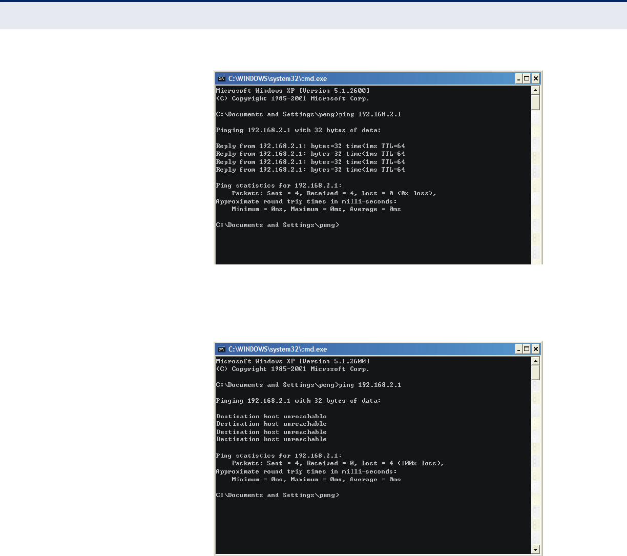
Now you can run the Ping command from the command prompt to verify
the network connection between your PC and the Router. The following
example is for Windows 2000 OS.
Open a command prompt, and type “ping 192.168.2.1” and then press
Enter.
If the displayed result is similar to the following figure, it means the
connection between your PC and the Router is functioning.
C
HAPTER
3
| Quick Installation Guide
TCP/IP Configuration
– 21 –
Figure 4: Success Result of a Ping Command
If the displayed result is similar to the following figure, it means the
connection between your PC and the Router is not functioning.
Figure 5: Failure of a Ping Command
To check the connection, follow these steps:
1. Verify that the LAN port LED to which the PC is connected on the Router
and the LED on your PC's network adapter are turned on.
2. Verify that the Router's IP address is 192.168.2.1, and that your PC's IP
address is within the range of 192.168.2.2 ~ 192.168.2.254.
C
HAPTER
3
| Quick Installation Guide
Quick Installation Guide
– 22 –
QUICK INSTALLATION GUIDE
With a Web-based (Internet Explorer or Netscape® Navigator) utility, it is
easy to configure and manage the SMCWGBR14-N2 Wireless N Gigabit
Router. The Web-based utility can be used on any Windows, Macintosh or
UNIX OS with a Web browser.
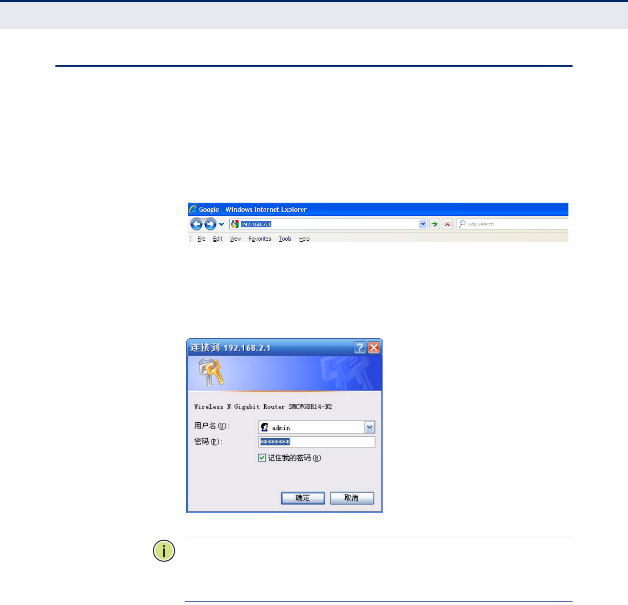
1. To access the configuration utility, open a web-browser and type the
default address http://192.168.2.1 in the address field of the browser.
Figure 6: Log in to the Router
After a moment, a login window will appear. Enter “admin” for the User
Name and “smcadmin” for the Password, both in lower case letters.
Then click the OK button or press the Enter key.
Figure 7: Login Windows
N
OTE
:
If the above screen does not display, it means that your Web-
browser has been set to a proxy. Go to Tools menu>Internet
Options>Connections>LAN Settings, in the screen that appears, cancel the
Using Proxy checkbox, and click OK to finish it.
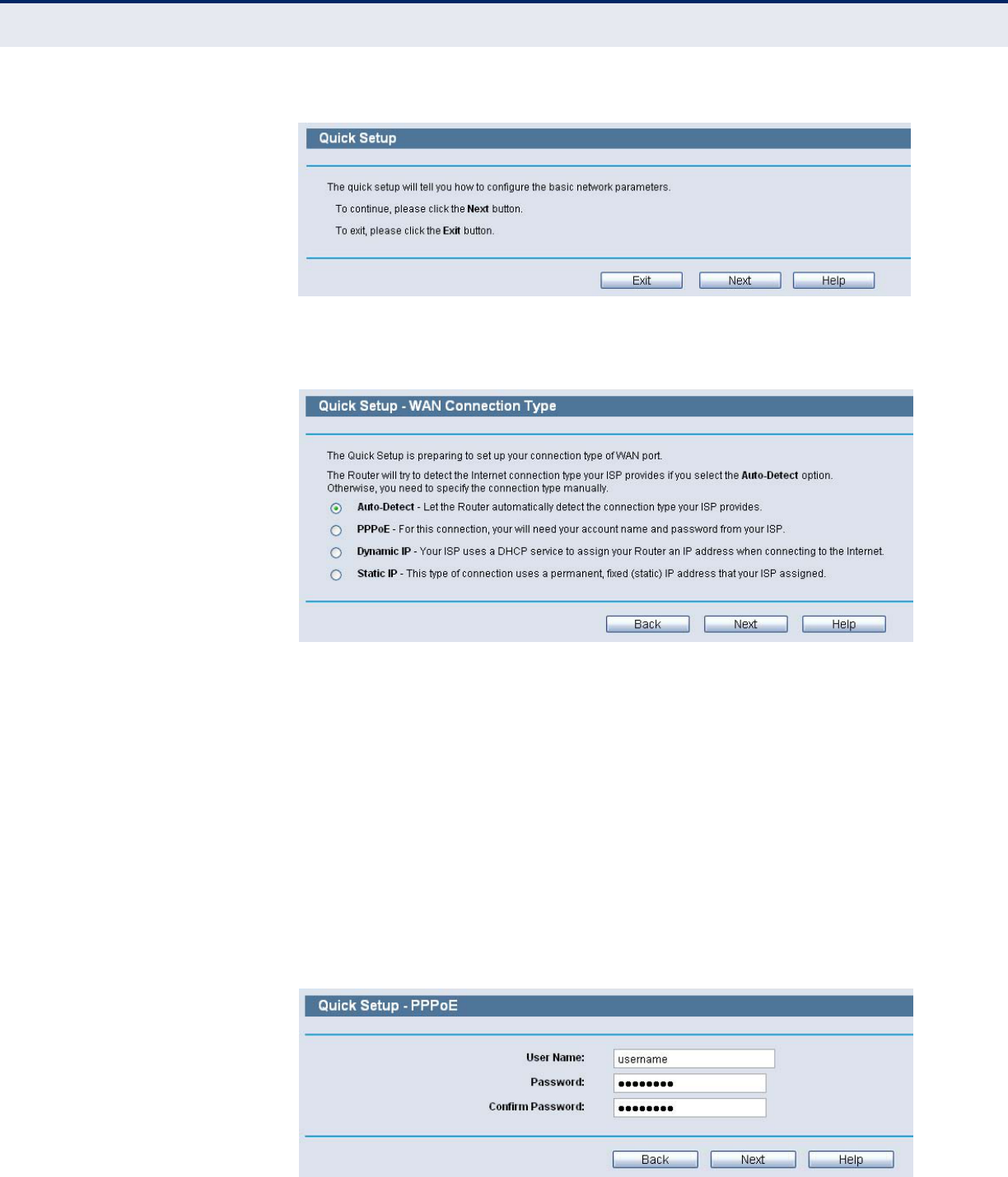
2. After successfully login, you can click the Quick Setup to quickly
configure your Router.
C
HAPTER
3
| Quick Installation Guide
Quick Installation Guide
– 23 –
Figure 8: Quick Setup
3. Click Next, and then WAN Connection Type page will appear.
Figure 9: Choose WAN Connection Type
The Router provides Auto-Detect function and supports three popular
ways PPPoE, Dynamic IP, and Static IP, to connect to the Internet. It is
recommended that you make use of the Auto-Detect function. If you
are sure of what kind of connection type your ISP provides, you can
select the type and click Next to go on configuring.
4. If you select Auto-Detect, the Router will automatically detect the
connection type your ISP provides. Make sure the cable is securely
plugged into the WAN port before detection. The appropriate
configuration page will be displayed when an active Internet service is
successfully detected by the Router.
a. If the connection type detected is PPPoE, the next screen will
appear.
Figure 10: Quick Setup - PPPoE
C
HAPTER
3
| Quick Installation Guide
Quick Installation Guide
– 24 –
■User Name and Password - Enter the User Name and Password
provided by your ISP. These fields are case sensitive. If you have
difficulty with this process, please contact your ISP.
b. If the connection type detected is Dynamic IP, you can go on with
the wireless configuration, as shown in Figure 12 on page 25.
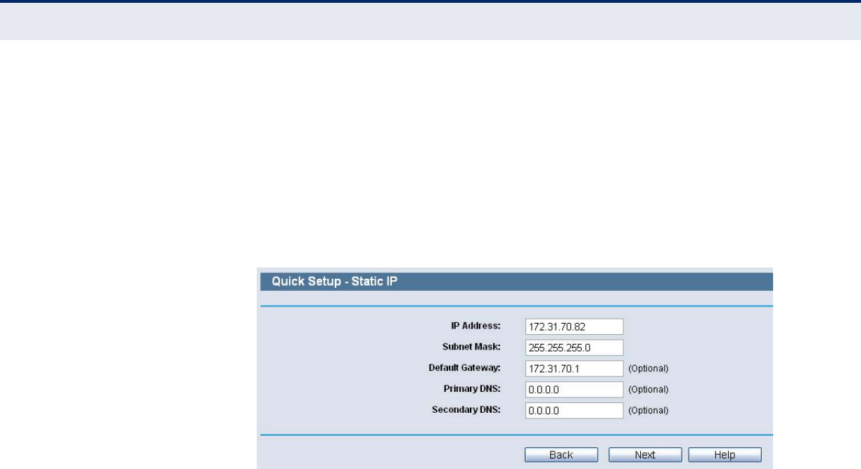
c. If the connection type detected is Static IP, the next screen will
appear.
Figure 11: Quick Setup - Static IP
■IP Address - This is the WAN IP address as seen by external users
on the Internet (including your ISP). Enter the IP address into the
field.
■Subnet Mask - The Subnet Mask is used for the WAN IP address, it
is usually 255.255.255.0.
■Default Gateway - Enter the gateway IP address into the box, if
required.
■Primary DNS - Enter the DNS Server IP address into the box, if
required.
■Secondary DNS - If your ISP provides another DNS server, enter it
into this field.
5. Click Next to continue, the Wireless settings page will appear.
C
HAPTER
3
| Quick Installation Guide
Quick Installation Guide
– 25 –
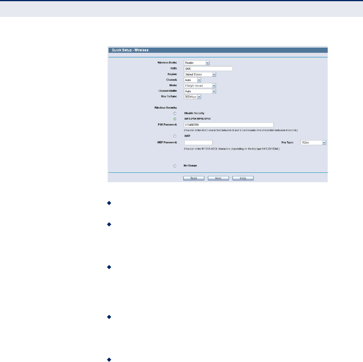
Figure 12: Quick Setup - Wireless
Wireless Radio - Enable or disable the wireless radio choosing from
the pull-down list.
SSID - Enter a value of up to 32 characters. The same name of SSID
(Service Set Identification) must be assigned to all wireless devices in
your network. Considering your wireless network security, the default
SSID is set to be “SMC”. This value is case-sensitive. For example,
“TEST” is NOT the same as “test”.
Region - Select your region from the pull-down list. This field specifies
the region where the wireless function of the Router can be used. It
may be illegal to use the wireless function of the Router in a region
other than one of those specified in this field. If your country or region
is not listed, please contact your local government agency for
assistance.
Channel - This field determines which operating frequency will be
used. The default channel is set to Auto, so the AP will choose the best
channel automatically. It is not necessary to change the wireless
channel unless you notice interference problems with another nearby
access point.
Mode - This field determines the wireless mode which the Router works
on.
C
HAPTER
3
| Quick Installation Guide
Quick Installation Guide
– 26 –
Channel Width - Select any channel width from the pull-down list. The
default setting is automatic, which can adjust the channel width for
your clients automatically.
Max Tx Rate - You can limit the maximum transmission rate of the
Router through this field.
Disable Security - The wireless security function can be enabled or
disabled. If disabled, the wireless stations will be able to connect the
Router without encryption. It is recommended strongly that you choose
one of following options to enable security.
WPA-PSK/WPA2-PSK - Select WPA based on pre-shared passphrase.
PSK Password - You can enter ASCII or Hexadecimal characters.
For ASCII, the key can be made up of any numbers 0 to 9 and any
letters A to Z, the length should be between 8 and 63 characters.
For Hexadecimal, the key can be made up of any numbers 0 to 9
and letters A to F, the length should be between 8 and 64
characters.
Please also note the key is case sensitive, this means that upper
and lower case keys will affect the outcome. It would also be a good
idea to write down the key and all related wireless security settings.
No Change - If you chose this option, wireless security configuration
will not change!
These settings are only for basic wireless parameters. For advanced
settings, please refer to “Wireless Settings” on page 47.
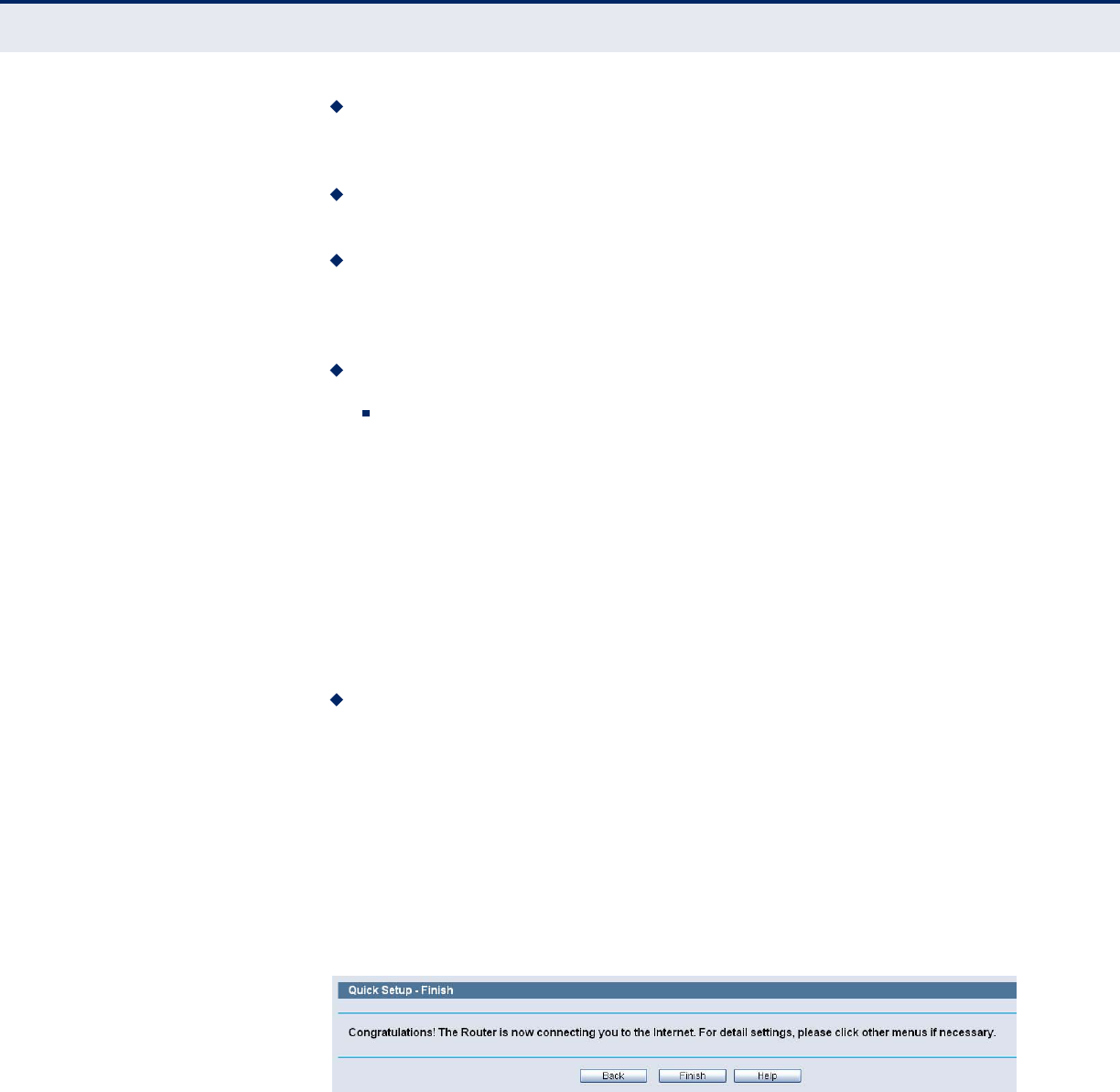
6. Click the Next button. You will then see the Finish page.
If you don’t make any changes on the Wireless page, you will see the
Finish page as below. Click the Finish button to finish the Quick Setup.
Figure 13: Quick Setup - Finish
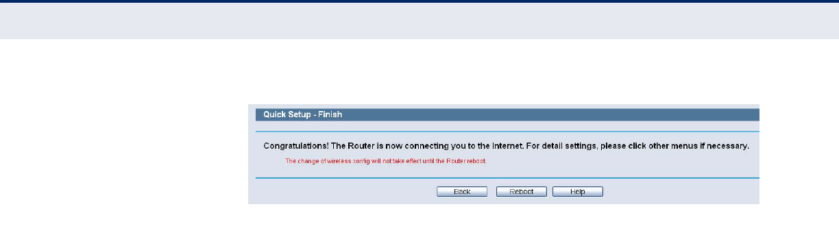
If there is something changed on the Wireless page, you will see the Finish
page as in the following figure. Click the Reboot button to make your
wireless configuration take effect and finish the Quick Setup.
C
HAPTER
3
| Quick Installation Guide
Quick Installation Guide
– 27 –
Figure 14: Quick Setup - reboot
– 28 –
4CONFIGURING THE ROUTER
This chapter will show each Web page's key functions and the configuration
method.
LOGIN
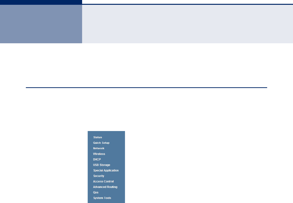
After your successful login, you will see the twelve main menus on the left
of the Web-based utility. On the right, there are the corresponding
explanations and instructions.
Figure 15: Main Menu
The detailed explanations for each Web page’s key function are listed
below.
C
HAPTER
4
| Configuring the Router
Status
– 29 –
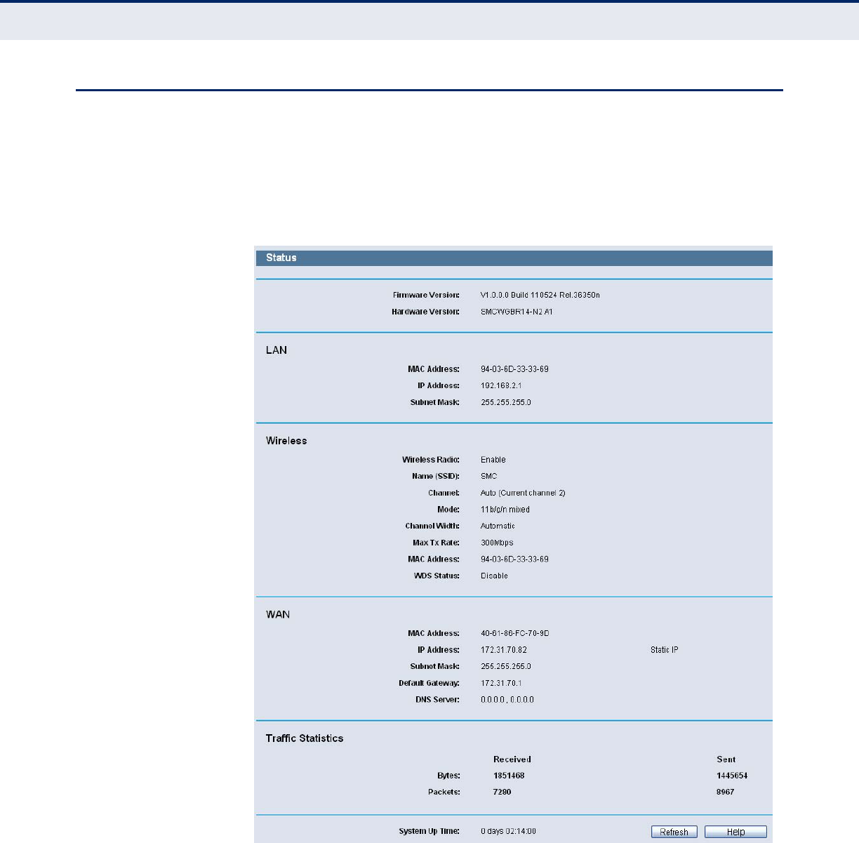
STATUS
GENERAL STATUS The Status page provides the current status information about the Router.
All information is read-only.
Figure 16: Router Status
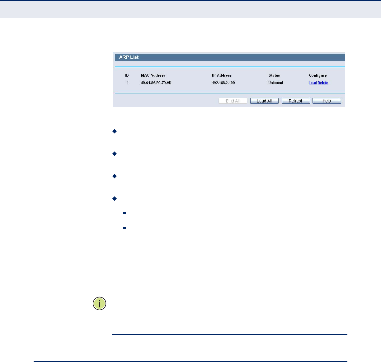
ARP LIST To manage the computer, you could observe the computers in the LAN by
checking the relationship of MAC address and IP address on the ARP list,
and you could configure the items on the ARP list also. This page displays
the ARP List; it shows all the existing IP & MAC Binding entrie.
C
HAPTER
4
| Configuring the Router
Quick Setup
– 30 –
Figure 17: ARP List
MAC Address - The MAC address of the controlled computer in the
LAN.
IP Address - The assigned IP address of the controlled computer in
the LAN.
Status - Indicates whether or not the MAC and IP addresses are
bound.
Configure - Load or delete an item.
Load - Load the item to the IP & MAC Binding list.
Delete - Delete the item.
Click the Bind All button to bind all the current items, available after
enable.
Click the Load All button to load all items to the IP & MAC Binding list.
Click the Refresh button to refresh all items.
N
OTE
:
An item could not be loaded to the IP & MAC Binding list if the IP
address of the item has been loaded before. Error warning will prompt as
well. Likewise, "Load All" only loads the items without interference to the IP
& MAC Binding list.
QUICK SETUP
Please refer to “Quick Installation Guide” on page 20.
– 31 –
5NETWORK SETTINGS
There are five submenus under the Network menu: WAN, MAC Clone, LAN,
Dynamic DNS and Binding Settings. Click any of them, and you will be able
to configure the corresponding function.
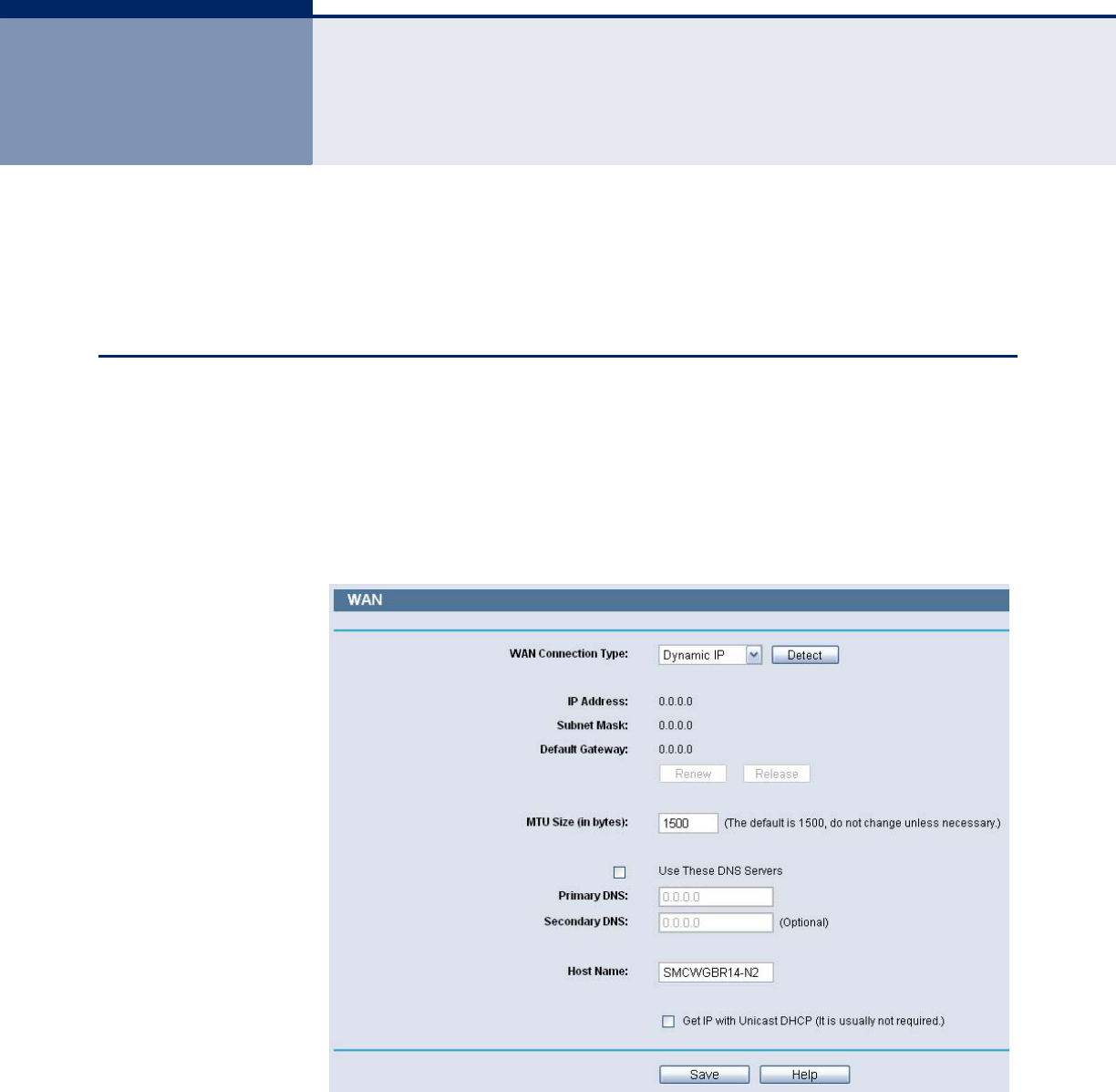
WAN
Choose menu “Network->WAN”, you can configure the IP parameters of
the WAN on the screen below.
If your ISP provides the DHCP service, please choose Dynamic IP type, and
the Router will automatically get IP parameters from your ISP. You can see
the page as follows.
Figure 18: WAN-Dynamic IP
This page displays the WAN IP parameters assigned dynamically by your
ISP, including IP address, Subnet Mask, Default Gateway, etc. Click the
Renew button to renew the IP parameters from your ISP. Click the Release
button to release the IP parameters.
C
HAPTER
5
| Network Settings
WAN
– 32 –
◆MTU Size - The normal MTU (Maximum Transmission Unit) value for
most Ethernet networks is 1500 Bytes. It is not recommended that you
change the default MTU Size unless required by your ISP.
◆Use These DNS Servers - If your ISP gives you one or two DNS
addresses, select Use These DNS Servers and enter the primary and
secondary addresses into the correct fields. Otherwise, the DNS servers
will be assigned dynamically from your ISP.
N
OTE
:
If you find error when you go to a Web site after entering the DNS
addresses, it is likely that your DNS servers are set up improperly. You
should contact your ISP to get DNS server addresses.
◆Get IP with Unicast DHCP - A few ISPs' DHCP servers do not support
the broadcast applications. If you cannot get the IP Address normally,
you can choose this option. (It is rarely required.)
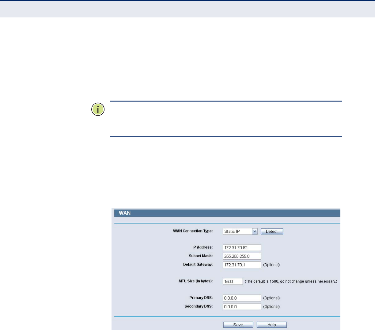
If your ISP provides a static or fixed IP Address, Subnet Mask, Gateway
and DNS setting, select Static IP. The Static IP settings page will appear.
Figure 19: WAN-Static IP
◆IP Address - Enter the IP address in dotted-decimal notation provided
by your ISP.
◆Subnet Mask - Enter the subnet Mask in dotted-decimal notation
provided by your ISP, usually is 255.255.255.0.
◆Default Gateway - (Optional) Enter the gateway IP address in dotted-
decimal notation provided by your ISP.
◆MTU Size - The normal MTU (Maximum Transmission Unit) value for
most Ethernet networks is 1500 Bytes. It is not recommended that you
change the default MTU Size unless required by your ISP.
C
HAPTER
5
| Network Settings
WAN
– 33 –
Primary/Secondary DNS - (Optional) Enter one or two DNS
addresses in dotted-decimal notation provided by your ISP.
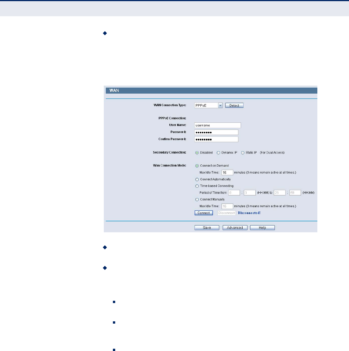
If your ISP provides a PPPoE connection, select PPPoE option, then enter
the following parameters:
Figure 20: WAN-PPPoE
User Name/Password - Enter the User Name and Password provided
by your ISP. These fields are case-sensitive.
Secondary Connection - It’s available only for PPPoE Connection. If
your ISP provides an extra Connection type such as Dynamic/Static IP
to connect to a local area network, then you can check the radio button
of Dynamic/Static IP to activate this secondary connection.
Disabled - The Secondary Connection is disabled by default, so
there is PPPoE connection only. This is recommended.
Dynamic IP - You can check this radio button to use Dynamic IP as
the secondary connection to connect to the local area network
provided by ISP.
Static IP - You can check this radio button to use Static IP as the
secondary connection to connect to the local area network provided
by ISP.
C
HAPTER
5
| Network Settings
WAN
– 34 –
◆Connect on Demand - In this mode, the Internet connection can be
terminated automatically after a specified inactivity period (Max Idle
Time) and be re-established when you attempt to access the Internet
again. If you want your Internet connection keeps active all the time,
please enter “0” in the Max Idle Time field. Otherwise, enter the
number of minutes you want to have elapsed before your Internet
access disconnects.
◆Connect Automatically - The connection can be re-established
automatically when it was down.
◆Time-based Connecting - The connection will only be established in
the period from the start time to the end time (both are in HH:MM
format).
N
OTE
:
Only when you have configured the system time on System Tools ->
Time page, will the Time-based Connecting function can take effect.
◆Connect Manually - You can click the Connect/ Disconnect button to
connect/disconnect immediately. This mode also supports the Max Idle
Time function as Connect on Demand mode. The Internet connection
can be disconnected automatically after a specified inactivity period and
re-established when you attempt to access the Internet again.
C
AUTION
:
Sometimes the connection cannot be terminated even though
you specify a Max Idle Time, since some applications are visiting the
Internet continually in the background.
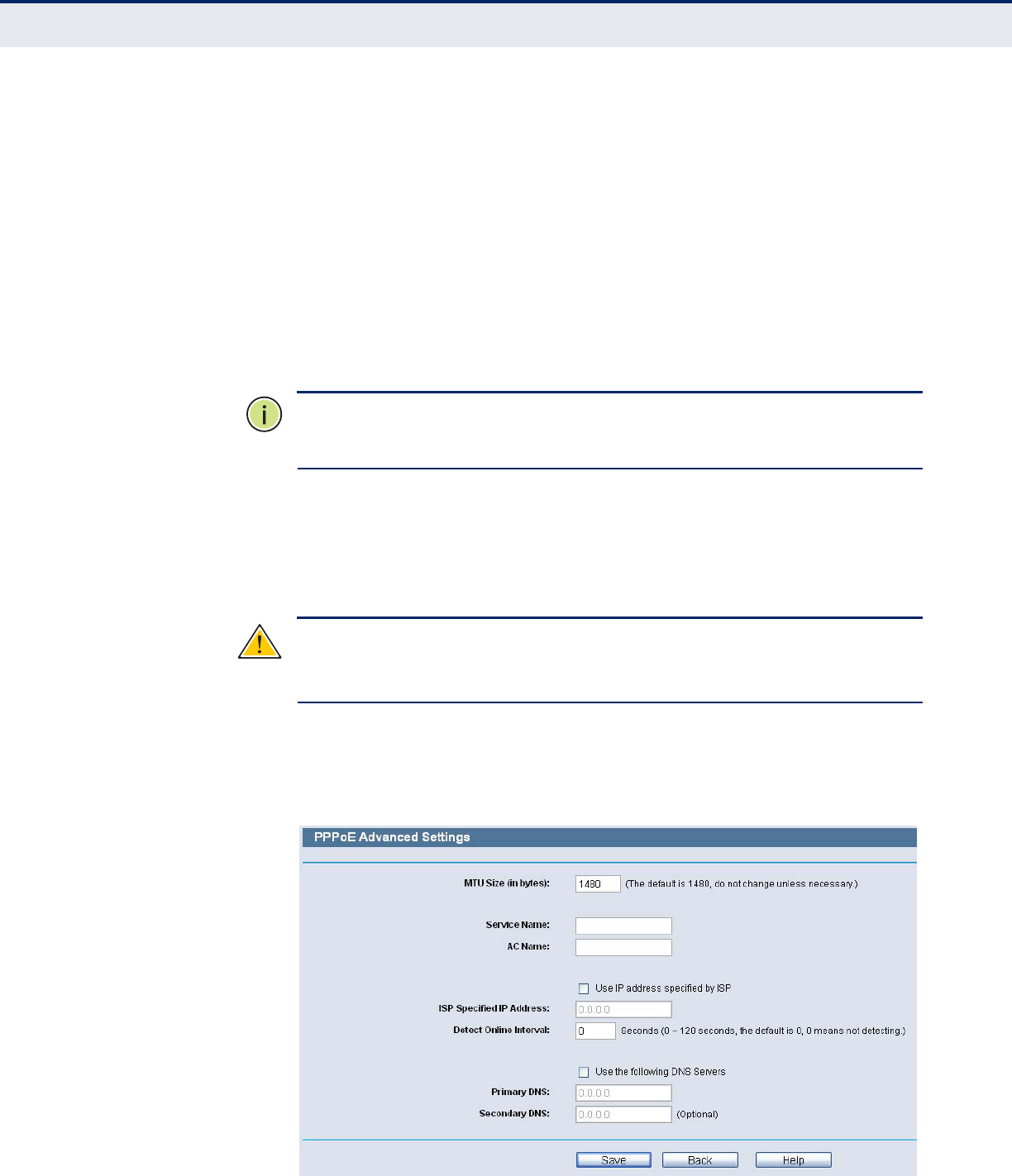
If you want to do some advanced configurations, please click the Advanced
button, and the advanced settings page will appear:
Figure 21: WAN-PPPoE Advanced Settings
C
HAPTER
5
| Network Settings
WAN
– 35 –
◆MTU Size - The default MTU size is “1480” bytes, which is usually fine.
It is not recommended that you change the default MTU Size unless
required by your ISP.
◆Service Name/AC Name - The service name and AC (Access
Concentrator) name, which should not be configured unless you are
sure it is necessary for your ISP. In most cases, leaving these fields
blank will work.
◆ISP Specified IP Address - If your ISP does not automatically assign
IP addresses to the Router during login, please click “Use IP address
specified by ISP” check box and enter the IP address provided by your
ISP in dotted-decimal notation.
◆Detect Online Interval - The Router will detect Access Concentrator
online at every interval. The default value is “0”. You can input the
value between “0”and “120”. The value “0” means no detect.
◆DNS IP address - If your ISP does not automatically assign DNS
addresses to the Router during login, please click “Use the following
DNS servers” check box and enter the IP address in dotted-decimal
notation of your ISP’s primary DNS server. If a secondary DNS server
address is available, enter it as well.
Click the Save button to save your settings.
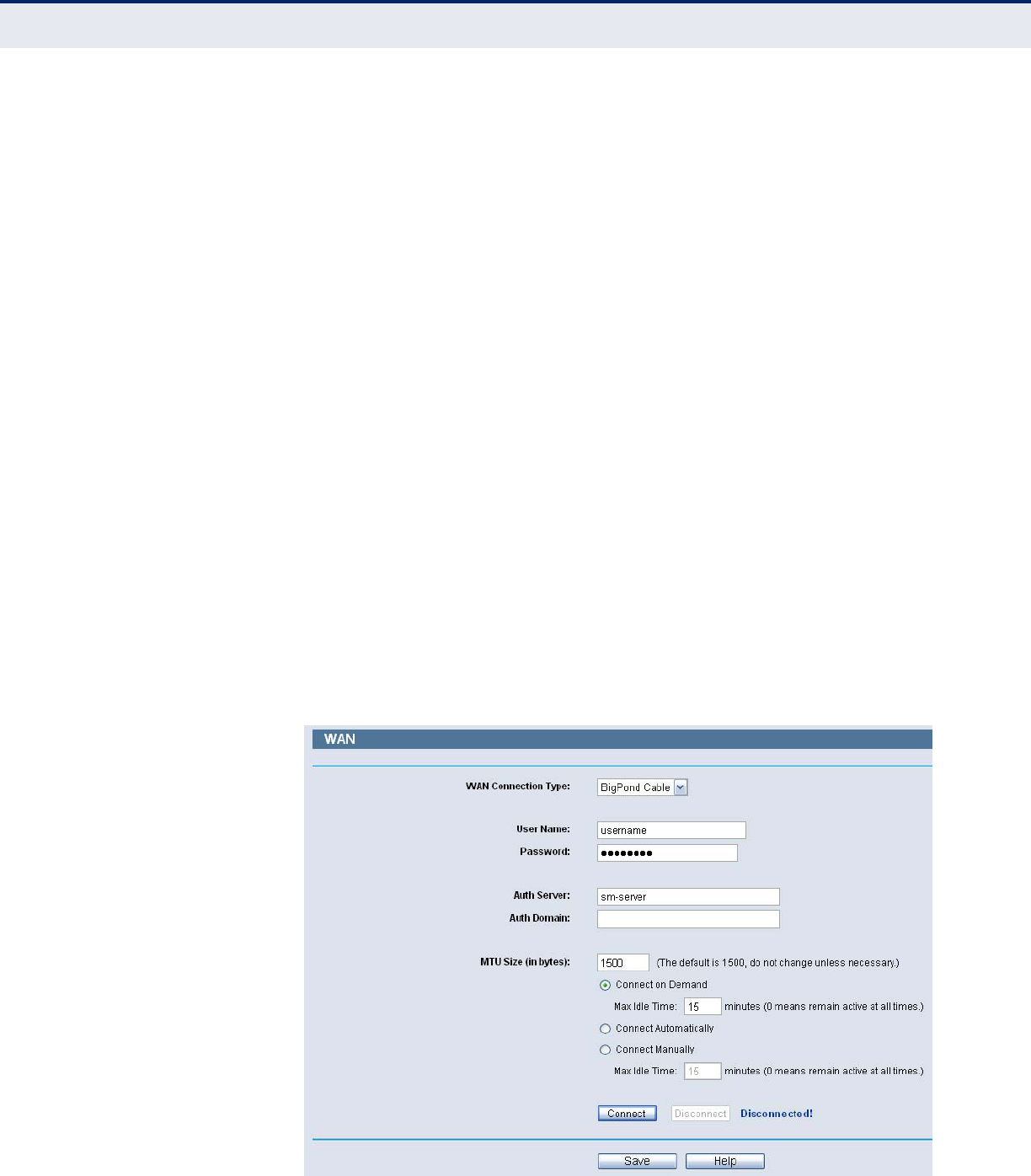
If your ISP provides BigPond Cable (or Heart Beat Signal) connection,
please select BigPond Cable, then enter the following parameters:
Figure 22: WAN-BigPond Cable

C
HAPTER
5
| Network Settings
WAN
– 36 –
◆User Name/Password - Enter the User Name and Password provided
by your ISP. These fields are case-sensitive.
◆Auth Server - Enter the authenticating server IP address or host
name.
◆Auth Domain - Type in the domain suffix server name based on your
location.
For example:
NSW / ACT - nsw.bigpond.net.au
VIC / TAS / WA / SA / NT - vic.bigpond.net.au
QLD - qld.bigpond.net.au
◆MTU Size - The normal MTU (Maximum Transmission Unit) value for
most Ethernet networks is 1500 Bytes. It is not recommended that you
change the default MTU Size unless required by your ISP.
◆Connect on Demand - In this mode, the Internet connection can be
terminated automatically after a specified inactivity period (Max Idle
Time) and be re-established when you attempt to access the Internet
again. If you want your Internet connection keeps active all the time,
please enter “0” in the Max Idle Time field. Otherwise, enter the
number of minutes you want to have elapsed before your Internet
access disconnects.
◆Connect Automatically - The connection can be re-established
automatically when it was down.
◆Connect Manually - You can click the Connect/Disconnect button to
connect/disconnect immediately. This mode also supports the Max Idle
Time function as Connect on Demand mode. The Internet connection
can be disconnected automatically after a specified inactivity period and
re-established when you attempt to access the Internet again. Click the
Connect button to connect immediately. Click the Disconnect button to
disconnect immediately.
C
AUTION
:
Sometimes the connection cannot be terminated even though
you specify a Max Idle Time because some applications may be visiting the
Internet continually in the background.
C
HAPTER
5
| Network Settings
WAN
– 37 –
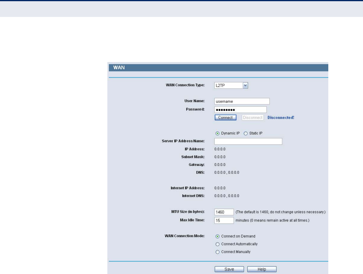
If your ISP provides L2TP connection, please select L2TP option, then enter
the following parameters :
Figure 23: WAN-L2TP
◆User Name/Password - Enter the User Name and Password provided
by your ISP. These fields are case-sensitive.
◆Dynamic IP/ Static IP - Choose either as you are given by your ISP.
Click the Connect button to connect immediately. Click the Disconnect
button to disconnect immediately.
◆Connect on Demand - You can configure the Router to disconnect
from your Internet connection after a specified period of inactivity (Max
Idle Time). If your Internet connection has been terminated due to
inactivity, Connect on Demand enables the Router to automatically re-
establish your connection as soon as you attempt to access the Internet
again. If you wish to activate Connect on Demand, click the radio
button. If you want your Internet connection to remain active at all
times, enter 0 in the Max Idle Time field. Otherwise, enter the number
of minutes you want to have elapsed before your Internet connection
terminates.
◆Connect Automatically - Connect automatically after the Router is
disconnected. To use this option, click the radio button.
C
HAPTER
5
| Network Settings
WAN
– 38 –
◆Connect Manually - You can configure the Router to make it connect
or disconnect manually. After a specified period of inactivity (Max Idle
Time), the Router will disconnect from your Internet connection, and
you will not be able to re-establish your connection automatically as
soon as you attempt to access the Internet again. To use this option,
click the radio button. If you want your Internet connection to remain
active at all times, enter "0" in the Max Idle Time field. Otherwise,
enter the number in minutes that you wish to have the Internet
connecting last unless a new link is requested.
C
AUTION
:
Sometimes the connection cannot be disconnected even though
you specify a Max Idle Time, since some applications may be visiting the
Internet continually in the background.
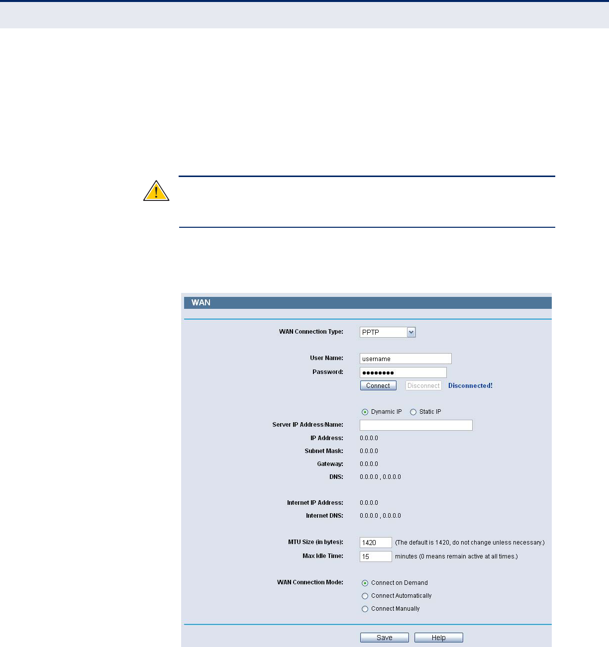
If your ISP provides PPTP connection, please select PPTP option, then enter
the following parameters:
Figure 24: WAN-PPTP
◆User Name/Password - Enter the User Name and Password provided
by your ISP. These fields are case-sensitive.
C
HAPTER
5
| Network Settings
WAN
– 39 –
◆Dynamic IP/ Static IP - Choose either as you are given by your ISP
and enter the ISP’s IP address or the domain name. If you choose static
IP and enter the domain name, you should also enter the DNS assigned
by your ISP. And click the Save button. Click the Connect button to
connect immediately. Click the Disconnect button to disconnect
immediately.
◆Connect on Demand - You can configure the Router to disconnect
from your Internet connection after a specified period of inactivity (Max
Idle Time). If your Internet connection has been terminated due to
inactivity, Connect on Demand enables the Router to automatically re-
establish your connection as soon as you attempt to access the Internet
again. If you wish to activate Connect on Demand, click the radio
button. If you want your Internet connection to remain active at all
times, enter 0 in the Max Idle Time field. Otherwise, enter the number
of minutes you want to have elapsed before your Internet connection
terminates.
◆Connect Automatically - Connect automatically after the Router is
disconnected. To use this option, click the radio button.
◆Connect Manually - You can configure the Router to make it connect
or disconnect manually. After a specified period of inactivity (Max Idle
Time), the Router will disconnect from your Internet connection, and
you will not be able to re-establish your connection automatically as
soon as you attempt to access the Internet again. To use this option,
click the radio button. If you want your Internet connection to remain
active at all times, enter "0" in the Max Idle Time field. Otherwise,
enter the number in minutes that you wish to have the Internet
connecting last unless a new link is requested.
C
AUTION
:
Sometimes the connection cannot be disconnected even though
you specify a Max Idle Time, since some applications may be visiting the
Internet continually in the background.
N
OTE
:
If you do not know how to choose the appropriate connection type,
click the Detect button to allow the Router to automatically search your
Internet connection for servers and protocols. The connection type will be
reported when an active Internet service is successfully detected by the
Router. This report is for your reference only. To make sure the connection
type your ISP provides, please refer to the ISP. The various types of
Internet connections that the Router can detect are as follows:
■PPPoE - Connections which use PPPoE that requires a user name
and password.
■Dynamic IP - Connections which use dynamic IP address
assignment.
■Static IP - Connections which use static IP address assignment.
C
HAPTER
5
| Network Settings
MAC Clone
– 40 –
The Router can not detect PPTP/L2TP/BigPond connections with your ISP. If
your ISP uses one of these protocols, then you must configure your
connection manually.
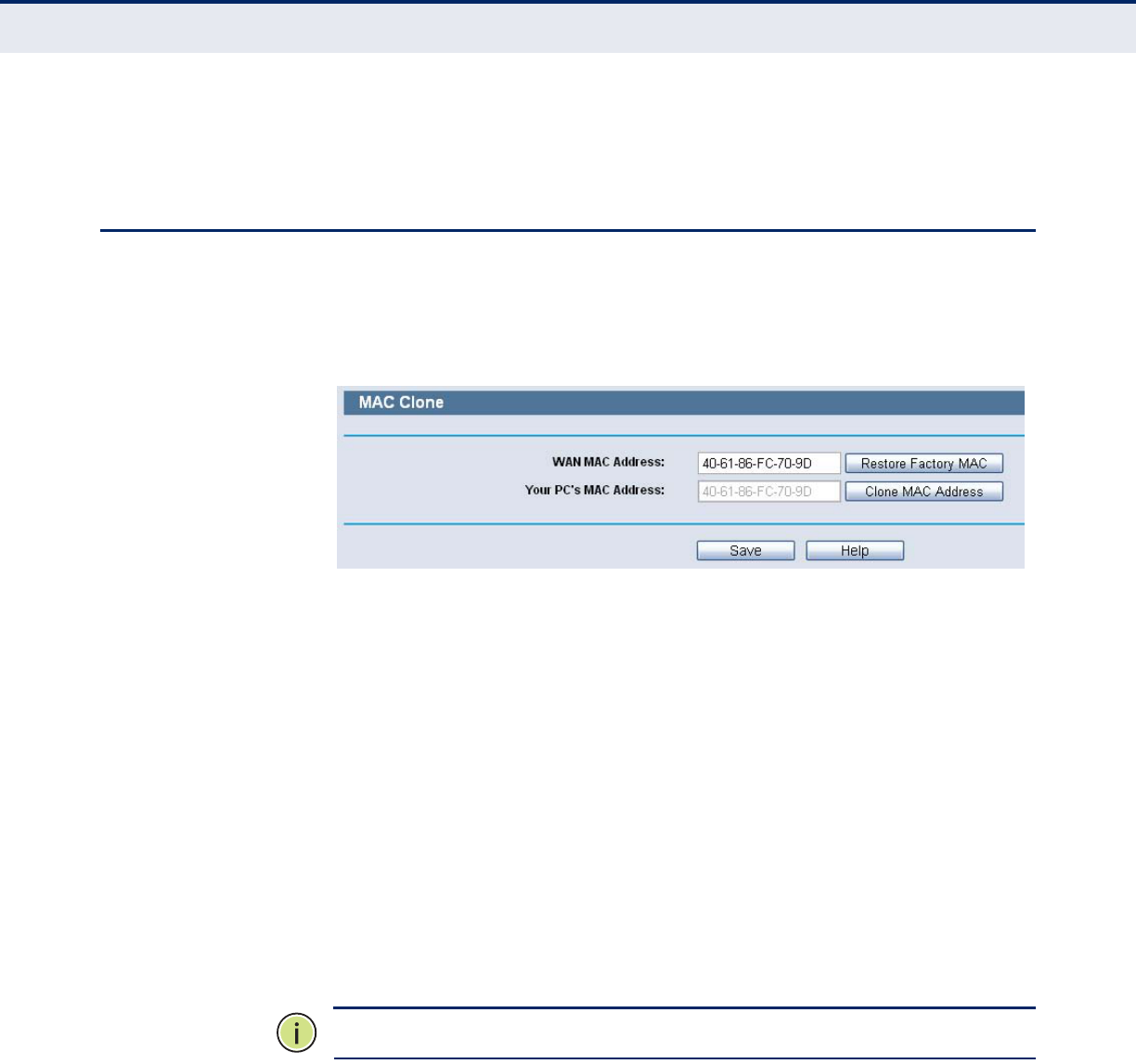
MAC CLONE
Choose menu “Network->MAC Clone”, you can configure the MAC address
of the WAN on the screen below:
Figure 25: MAC Address Clone
Some ISPs require that you register the MAC Address of your adapter.
Changes are rarely needed here.
◆WAN MAC Address - This field displays the current MAC address of
the WAN port. If your ISP requires you to register the MAC address,
please enter the correct MAC address into this field in XX-XX-XX-XX-XX-
XX format(X is any hexadecimal digit).
◆Your PC's MAC Address - This field displays the MAC address of the
PC that is managing the Router. If the MAC address is required, you can
click the Clone MAC Address To button and this MAC address will fill in
the WAN MAC Address field.
Click Restore Factory MAC to restore the MAC address of WAN port to the
factory default value.
Click the Save button to save your settings.
N
OTE
:
Only the PC on your LAN can use the MAC Address Clone function.
C
HAPTER
5
| Network Settings
LAN
– 41 –
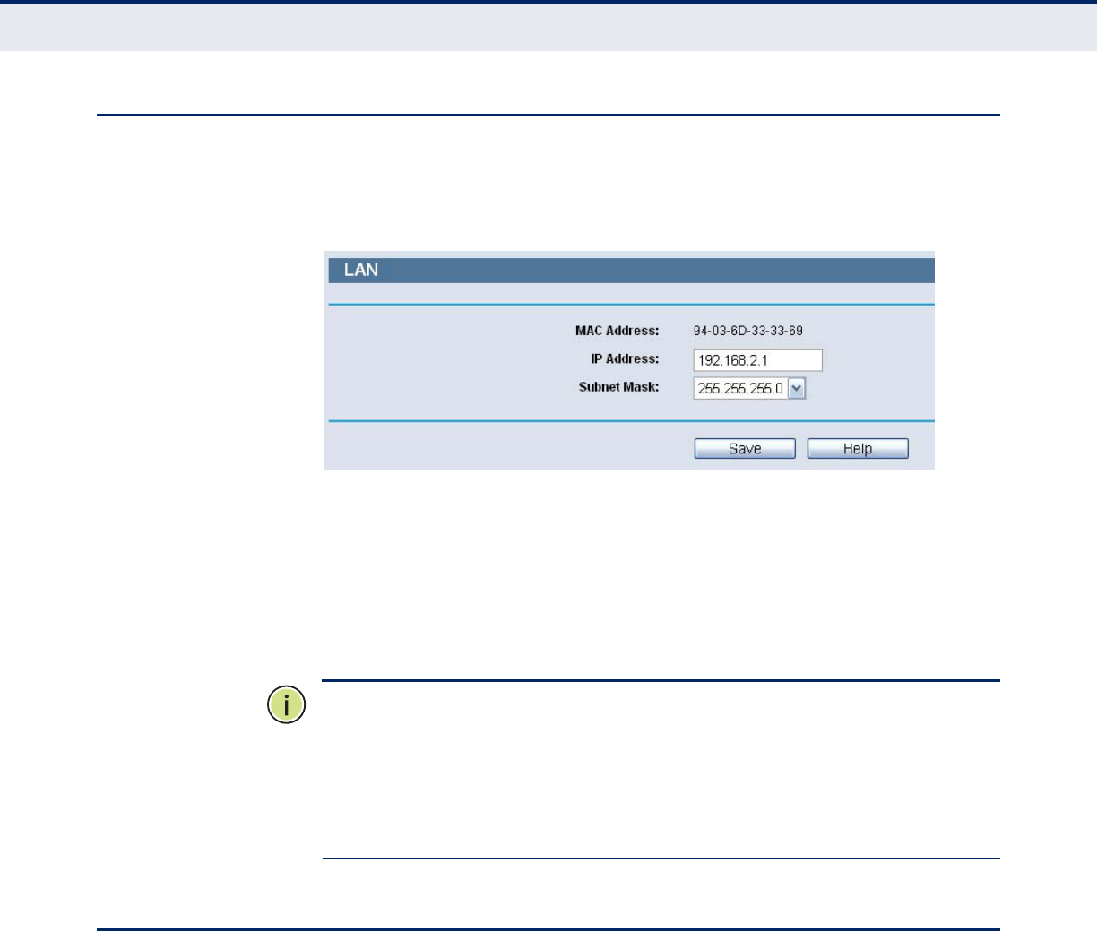
LAN
Choose menu “Network->LAN”, you can configure the IP parameters of the
LAN on the screen as below.
Figure 26: LAN Settings
◆MAC Address - The physical address of the Router, as seen from the
LAN. The value can't be changed.
◆IP Address - Enter the IP address of your Router or reset it in dotted-
decimal notation (factory default: 192.168.2.1).
◆Subnet Mask - An address code that determines the size of the
network. Normally use 255.255.255.0 as the subnet mask.
N
OTE
:
If you change the IP Address of LAN, you must use the new IP
Address to login the Router.
N
OTE
:
If the new LAN IP Address you set is not in the same subnet, the IP
Address pool of the DHCP server will change accordingly at the same time,
while the Virtual Server and DMZ Host will not take effect until they are re-
configured.
s
DYNAMIC DNS
Choose menu “Dynamic DNS”, and configure the Dynamic DNS function.
The Router offers the DDNS (Dynamic Domain Name System) feature,
which allows the hosting of a website, FTP server, or e-mail server with a
fixed domain name (named by yourself) and a dynamic IP address, and
then your friends can connect to your server by entering your domain
name no matter what your IP address is. Before using this feature, you
need to sign up for DDNS service providers such as www.comexe.cn,
www.dyndns.org, or www.no-ip.com. The Dynamic DNS client service
provider will give you a password or key.
C
HAPTER
5
| Network Settings
Dynamic DNS
– 42 –
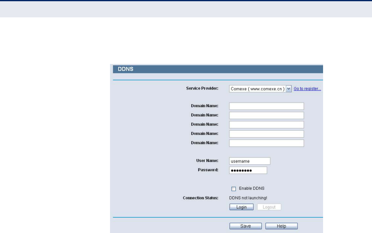
COMEXE.CN DDNS If the dynamic DNS Service Provider you select is www.comexe.cn, the
page will appear.
Figure 27: Comexe.cn DDNS Settings
To set up for DDNS, follow these instructions:
1. Type the Domain Name received from your dynamic DNS service
provider.
2. Type the User Name for your DDNS account.
3. Type the Password for your DDNS account.
4. Click the Login button to log in to the DDNS service.
■Connection Status -The status of the DDNS service connection is
displayed here.
Click Logout to log out of the DDNS service.
C
HAPTER
5
| Network Settings
Dynamic DNS
– 43 –
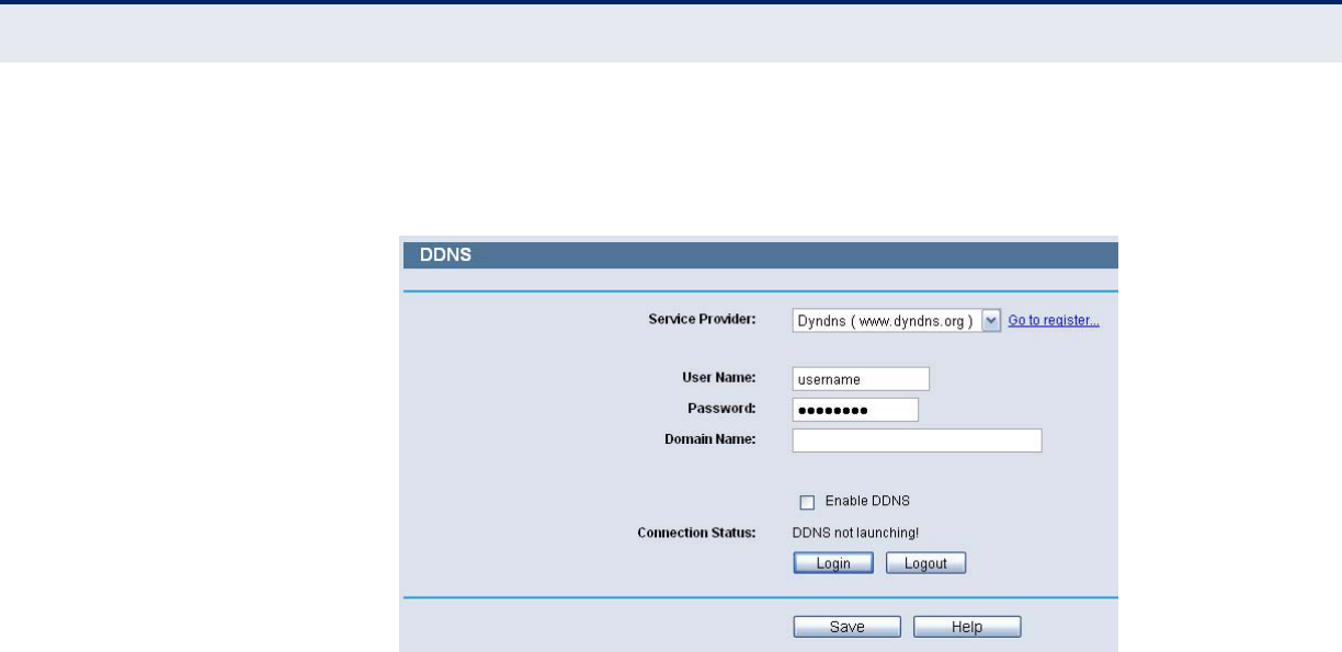
DYNDNS.ORG DDNS If the dynamic DNS Service Provider you select is www.dyndns.org, the
page will appear.
Figure 28: Dyndns.org DDNS Settings
To set up for DDNS, follow these instructions:
1. Type the User Name for your DDNS account.
2. Type the Password for your DDNS account.
3. Type the Domain Name you received from dynamic DNS service
provider here.
4. Click the Login button to log in to the DDNS service.
◆Connection Status - The status of the DDNS service connection is
displayed here.
Click Logout to logout of the DDNS service.
C
HAPTER
5
| Network Settings
Binding Setting
– 44 –
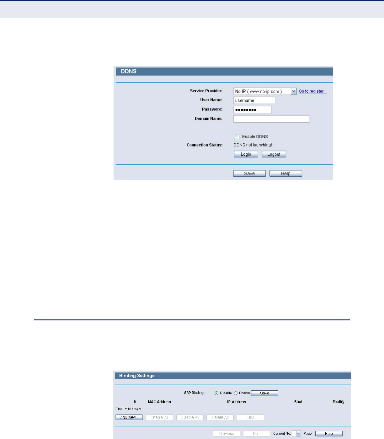
NO-IP.COM DDNS If the dynamic DNS Service Provider you select is www.no-ip.com, the
page will appear.
Figure 29: No-ip.com DDNS Settings
To set up for DDNS, follow these instructions:
1. Type the User Name for your DDNS account.
2. Type the Password for your DDNS account.
3. Type the Domain Name you received from dynamic DNS service
provider.
4. Click the Login button to log in the DDNS service.
◆Connection Status - The status of the DDNS service connection is
displayed here.
Click Logout to log out the DDNS service.
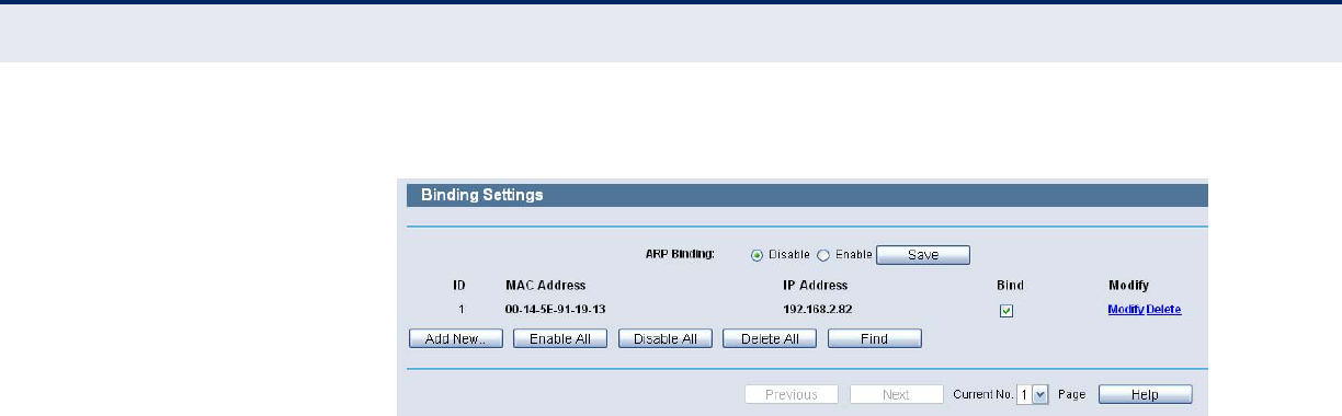
BINDING SETTING
This page displays the IP & MAC Binding Setting table; you can operate it in
accord with your desire.
Figure 30: Binding Settings
C
HAPTER
5
| Network Settings
Binding Setting
– 45 –
◆MAC Address - The MAC address of the controlled computer in the
LAN.
◆IP Address - The assigned IP address of the controlled computer in the
LAN.
◆Bind - Check this option to enable ARP binding for a specific device.
◆Modify - To modify or delete an existing entry.
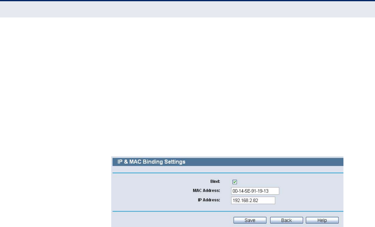
When you want to add or modify an IP & MAC Binding entry, you can click
the Add New button or Modify button, and then you will go to the next
page. This page is used for adding or modifying an IP & MAC Binding entry
.
Figure 31: IP & MAC Binding Settings (Add & Modify)
To add IP & MAC Binding entries, follow the steps below.
1. Click the Add New.
2. Enter the MAC Address and IP Address.
3. Select the Bind checkbox.
4. Click the Save button to save it.
To modify or delete an existing entry, follow the steps below.
1. Find the desired entry in the table.
2. Click Modify or Delete as desired on the Modify column.
To find an existing entry, follow the steps below.
1. Click the Find button.
2. Enter the MAC Address or IP Address.
3. Click the Find button in the page as shown in the following figure.
C
HAPTER
5
| Network Settings
Binding Setting
– 46 –
Figure 32: Find IP & MAC Binding Entry
Click the Enable All button to make all entries enabled.
Click the Delete All button to delete all entries.
– 47 –
6WIRELESS SETTINGS
There are six submenus under the Wireless menu: Wireless Settings,
Wireless Security, Wireless MAC Filtering, Wireless Advanced, Wireless
Statistics and WPS. Click any of them, and you will be able to configure the
corresponding function.
WIRELESS SETTINGS
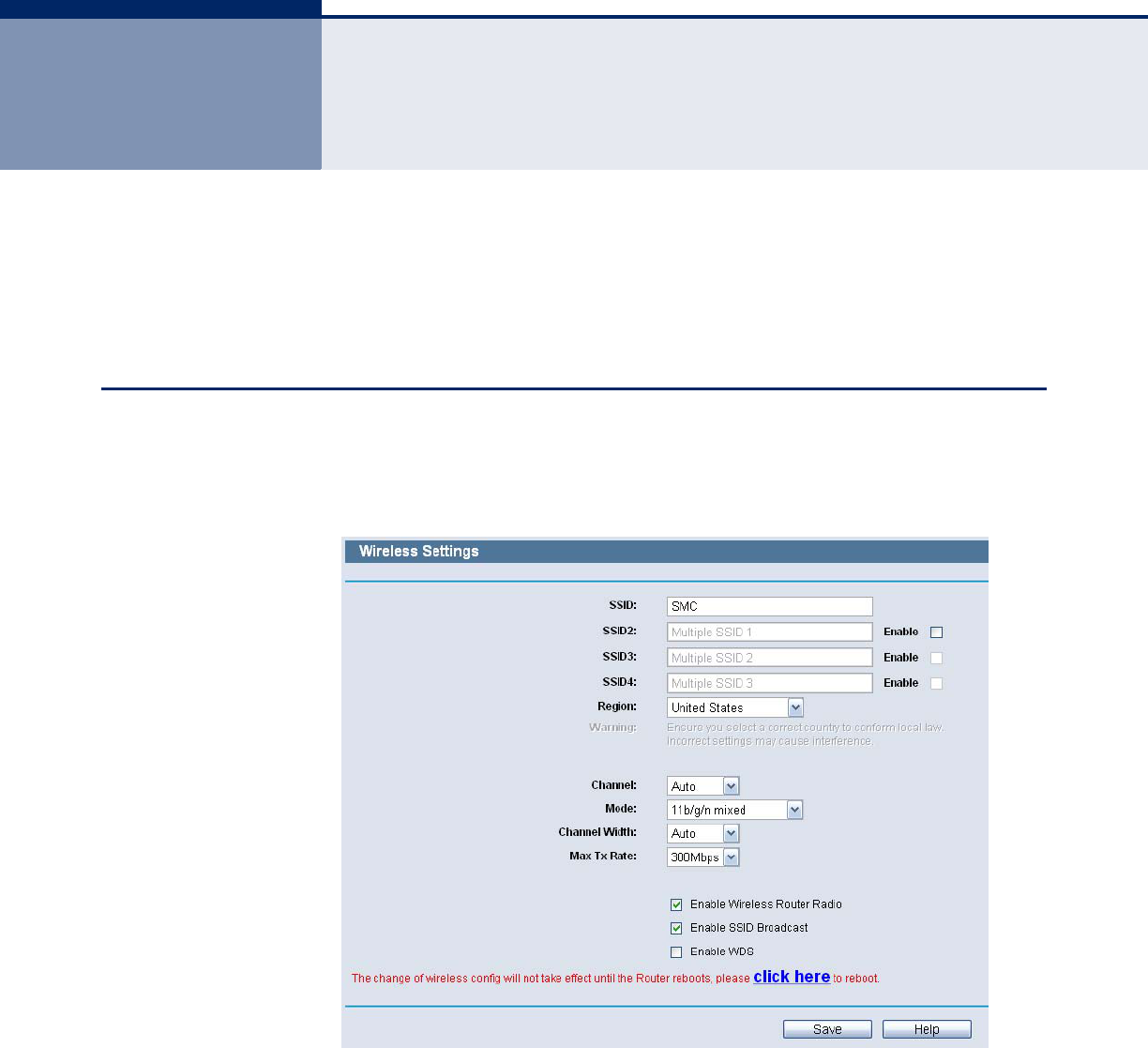
Choose menu “Wireless->Wireless Setting”, you can configure the basic
settings for the wireless network on this page.
Figure 33: Wireless Settings
◆SSID - Enter a value of up to 32 characters. The same name of SSID
(Service Set Identification) must be assigned to all wireless devices in
your network. Considering your wireless network security, the default
SSID is set to be “SMC”. This value is case-sensitive. For example,
“TEST” is NOT the same as “test”.
◆SSID (2-4) - Up to 4 SSIDs for each BSS can be set, the name can be
up to 32 characters. The Multi-SSID function is available only when
Enable is checked.
C
HAPTER
6
| Wireless Settings
Wireless Settings
– 48 –
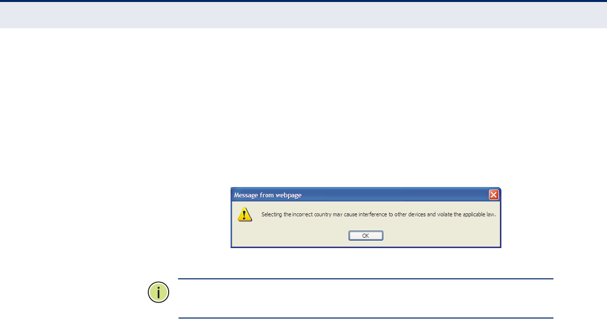
◆Region - Select your region from the pull-down list. This field specifies
the region where the wireless function of the Router can be used. It
may be illegal to use the wireless function of the Router in a region
other than one of those specified in this field. If your country or region
is not listed, please contact your local government agency for
assistance.
When you select your local region from the pull-down list, click the Save
button, then the Note Dialog appears. Click OK.
Figure 34: Note Dialog
N
OTE
:
Limited by local law regulations, version for North America does not
have region selection option.
◆Channel - This field determines which operating frequency will be
used. The default channel is set to Auto, so the AP will choose the best
channel automatically. It is not necessary to change the wireless
channel unless you notice interference problems with another nearby
access point.
◆Mode - Select the desired mode. The default setting is 11bgn mixed.
■11b only - Select if all of your wireless clients are 802.11b.
■11g only - Select if all of your wireless clients are 802.11g.
■11n only- Select only if all of your wireless clients are 802.11n.
■11b/g mixed - Select if you are using both 802.11b and 802.11g
wireless clients.
■11b/g/n mixed - Select if you are using a mix of 802.11b, 11g, and
11n wireless clients.
Select the desired wireless mode. When 802.11g mode is selected, only
802.11g wireless stations can connect to the Router. When 802.11n mode
is selected, only 802.11n wireless stations can connect to the AP. It is
strongly recommended that you set the Mode to 11b/g/n mixed, and all of
802.11b, 802.11g, and 802.11n wireless stations can connect to the
Router.
◆Channel width - Select any channel width from the pull-down list. The
default setting is automatic, which can adjust the channel width for
your clients automatically.
C
HAPTER
6
| Wireless Settings
Wireless Security
– 49 –
N
OTE
:
If 11b only, 11g only, or 11bg mixed is selected in the Mode field,
the Channel Width selecting field will turn grey and the value will become
20M, which is unable to be changed.
◆Max Tx Rate - You can limit the maximum tx rate of the Router
through this field.
◆Enable Wireless Router Radio - The wireless radio of this Router can
be enabled or disabled to allow wireless stations access.
◆Enable SSID Broadcast - When wireless clients survey the local area
for wireless networks to associate with, they will detect the SSID
broadcast by the Router. If you select the Enable SSID Broadcast
checkbox, the Wireless Router will broadcast its name (SSID) on the
air.
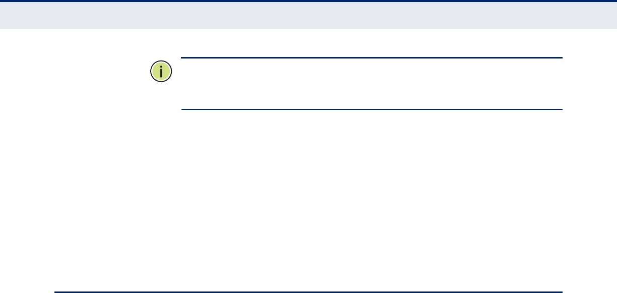
WIRELESS SECURITY
Choose menu “Wireless->Wireless Security”, you can configure the security
settings of your wireless network.
There are five wireless security modes supported by the Router: WEP
(Wired Equivalent Privacy), WPA (Wi-Fi Protected Access), WPA2 (Wi-Fi
Protected Access 2), WPA2-PSK (Pre-Shared Key), WPA-PSK (Pre-Shared
Key).
C
HAPTER
6
| Wireless Settings
Wireless Security
– 50 –
Figure 35: Wireless Security
Disable Security - If you do not want to use wireless security, select
this check box, but it’s strongly recommended to choose one of the
following modes to enable security.
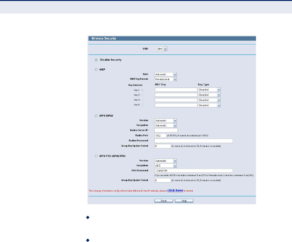
WEP - It is based on the IEEE 802.11 standard. If you select this check
box, you will find a notice in red as show in the following figure.
C
HAPTER
6
| Wireless Settings
Wireless Security
– 51 –
Figure 36: WEP
■Type - you can choose the type for the WEP security on the pull-
down list. The default setting is Automatic, which can select Open
System or Shared Key authentication type automatically based on
the wireless station's capability and request.
■WEP Key Format - Hexadecimal and ASCII formats are provided.
Hexadecimal format stands for any combination of hexadecimal
digits (0-9, a-f, A-F) in the specified length. ASCII format stands for
any combination of keyboard characters in the specified length.
■WEP Key- Select which of the four keys will be used and enter the
matching WEP key that you create. Make sure these values are
identical on all wireless stations in your network.
■Key Type - You can select the WEP key length (64-bit, or 128-bit, or
152-bit.) for encryption. "Disabled" means this WEP key entry is
invalid.
64-bit - You can enter 10 hexadecimal digits (any combination of 0-
9, a-f, A-F, zero key is not promoted) or 5 ASCII characters.
128-bit - You can enter 26 hexadecimal digits (any combination of
0-9, a-f, A-F, zero key is not promoted) or 13 ASCII characters.
152-bit - You can enter 32 hexadecimal digits (any combination of
0-9, a-f, A-F, zero key is not promoted) or 16 ASCII characters.
N
OTE
:
If you do not set the key, the wireless security function is still
disabled even if you have selected Shared Key as Authentication Type.
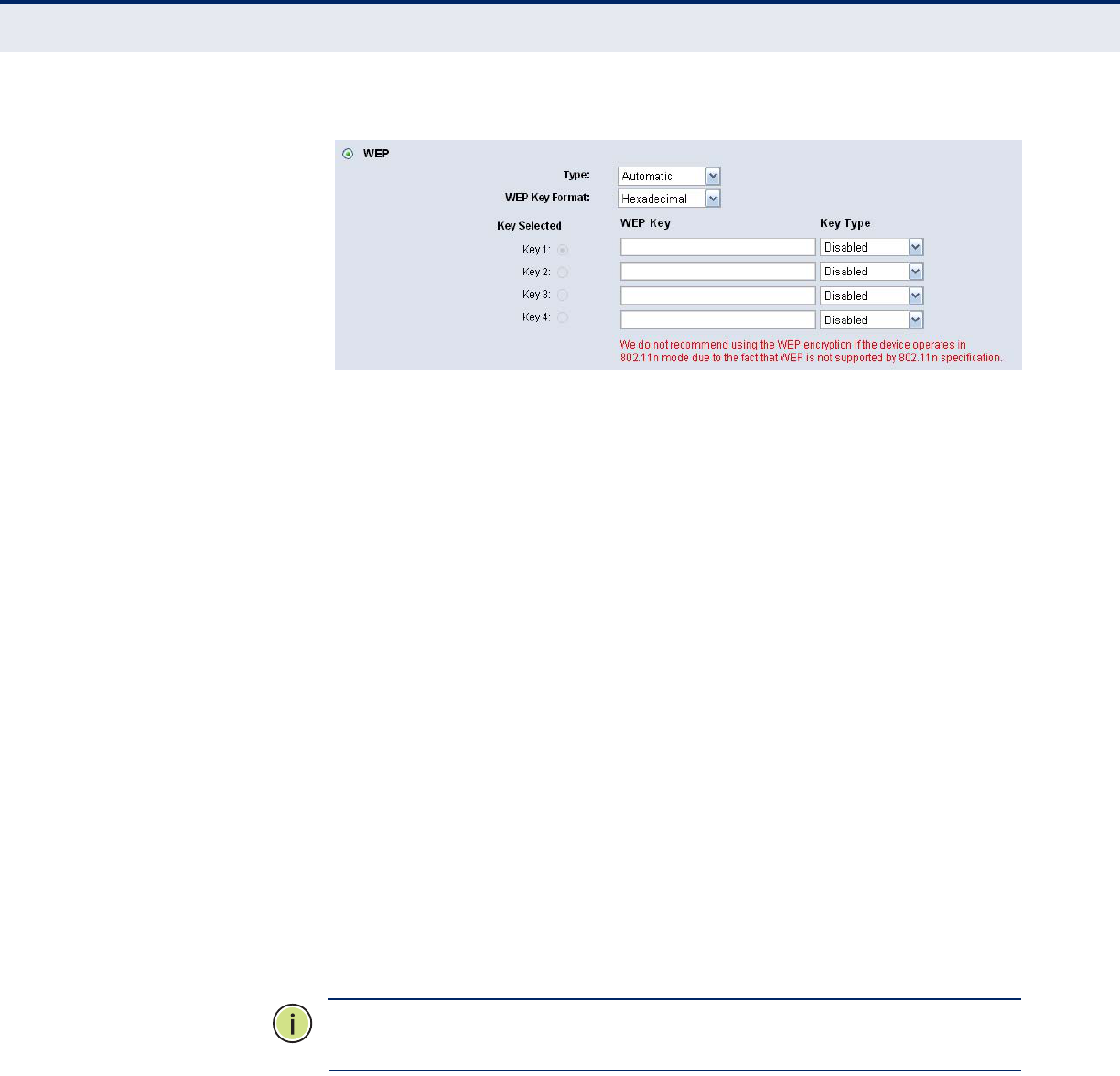
◆WPA /WPA2 - It’s based on Radius Server.
■Version - you can choose the version of the WPA security on the
pull-down list. The default setting is Automatic, which can select
WPA (Wi-Fi Protected Access) or WPA2 (WPA version 2)
automatically based on the wireless station's capability and request.
■Encryption - You can select either Automatic, or TKIP or AES.
C
HAPTER
6
| Wireless Settings
Wireless Security
– 52 –
N
OTE
:
If you check the WPA/WPA2 radio button and choose TKIP
encryption, you will find a notice in red.
Figure 37: WPA/WPA2
■Radius Server IP - Enter the IP address of the Radius Server.
■Radius Port - Enter the port that radius service used.
■Radius Password - Enter the password for the Radius Server.
■Group Key Update Period - Specify the group key update interval in
seconds. The value should be 30 or above. Enter 0 to disable the
update.
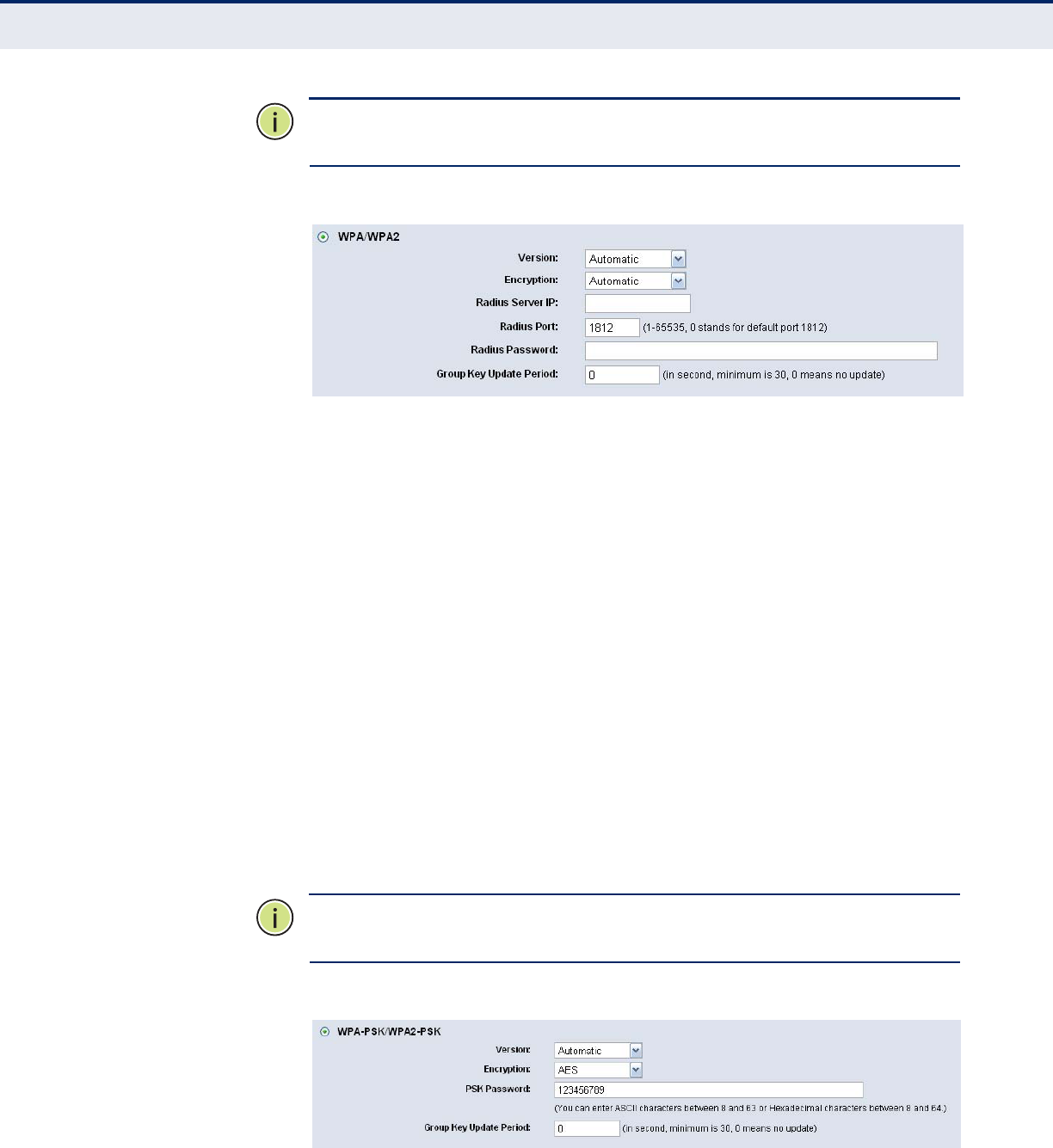
◆WPA-PSK/WPA2-PSK - It’s the WPA/WPA2 authentication type based
on pre-shared passphrase.
■Version - you can choose the version of the WPA-PSK security on
the drop-down list. The default setting is Automatic, which can
select WPA-PSK (Pre-shared key of WPA) or WPA2-PSK (Pre-shared
key of WPA) automatically based on the wireless station's capability
and request.
■Encryption - When WPA-PSK or WPA is set as the Authentication
Type, you can select either Automatic, or TKIP or AES as
Encryption.
N
OTE
:
If you check the WPA-PSK/WPA2-PSK radio button and choose TKIP
encryption, you will find a notice in red.
Figure 38: WPA-PSK/WPA2-PSK
C
HAPTER
6
| Wireless Settings
Wireless MAC Filtering
– 53 –
■PSK Passphrase - You can enter ASCII characters between 8 and 63
characters or 8 to 64 Hexadecimal characters.
■Group Key Update Period - Specify the group key update interval in
seconds. The value should be 30 or above. Enter 0 to disable the
update.
Be sure to click the Save button to save your settings on this page.
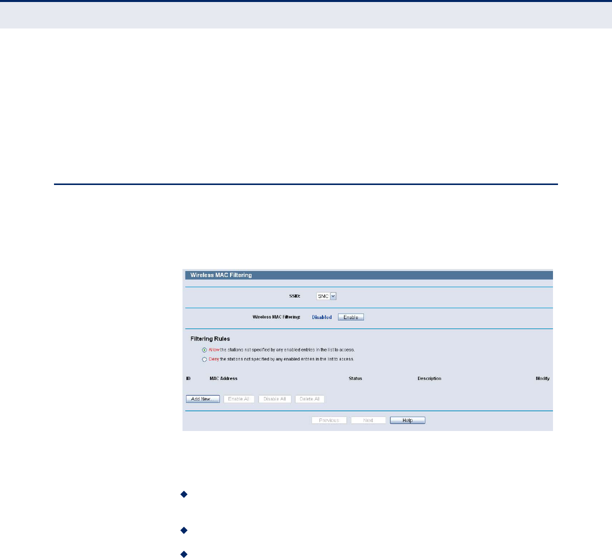
WIRELESS MAC FILTERING
Choose menu “Wireless->MAC Filtering”, you can control the wireless
access by configuring the Wireless MAC Address Filtering function.
Figure 39: Wireless MAC Address Filtering
To filter wireless users by MAC Address, click Enable. The default
setting is Disable.
MAC Address - The wireless station's MAC address that you want to
filter.
Status - The status of this entry either Enabled or Disabled.
Description - A simple description of the wireless station.
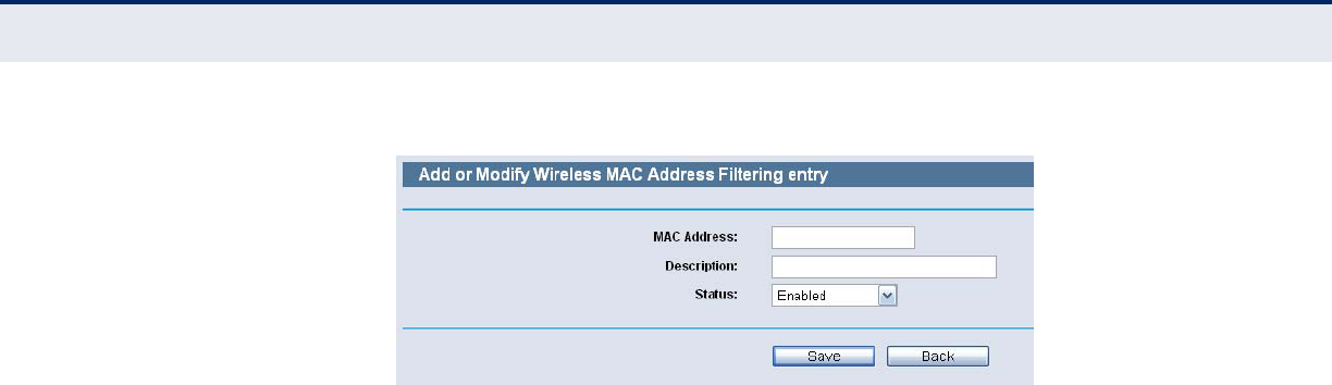
To Add a Wireless MAC Address filtering entry, click the Add New button.
The "Add or Modify Wireless MAC Address Filtering entry" page will appear:
C
HAPTER
6
| Wireless Settings
Wireless MAC Filtering
– 54 –
Figure 40: Add or Modify Wireless MAC Address Filtering Entry
To add or modify a MAC Address Filtering entry, follow these
instructions:
1. Enter the appropriate MAC Address into the MAC Address field. The
format of the MAC Address is XX-XX-XX-XX-XX-XX (X is any
hexadecimal digit). For example: 00-0A-EB-00-07-8A.
2. Enter a simple description of the wireless station in the Description
field. For example: Wireless station A.
3. Status - Select Enabled or Disabled for this entry on the Status pull-
down list.
4. Click the Save button to save this entry.
To modify or delete an existing entry:
1. Click the Modify in the entry you want to modify. If you want to delete
the entry, click the Delete.
2. Modify the information.
3. Click the Save button.
Click the Enable All button to make all entries enabled
Click the Disabled All button to make all entries disabled.
Click the Delete All button to delete all entries
Click the Next button to go to the next page
Click the Previous button to return to the previous page.
For example: If you desire that the wireless station A with MAC address 00-
0A-EB-00-07-8A and the wireless station B with MAC address 00-0A-EB-
00-23-11 are able to access the Router, but all the other wireless stations
cannot access the Router, you can configure the Wireless MAC Address
Filtering list by following these steps:
C
HAPTER
6
| Wireless Settings
Wireless Advanced
– 55 –
1. Click the Enable button to enable this function.
2. Select the radio button: Deny the stations not specified by any enabled
entries in the list to access for Filtering Rules.
3. Delete all or disable all entries if there are any entries already.
4. Click the Add New button and enter the MAC address 00-0A-EB-00-07-
8A /00-0A-EB-00-23-11 in the MAC Address field, then enter wireless
station A/B in the Description field, while select Enabled in the Status
pull-down list. Finally, click the Save and the Back button.
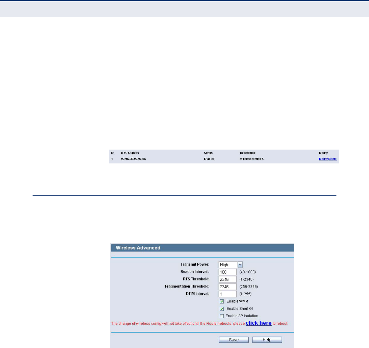
The filtering rules that configured should be similar to the following list:
Figure 41: Filtering Rules
WIRELESS ADVANCED
Choose menu “Wireless->Wireless Advanced”, you can configure the
advanced settings of your wireless network.
Figure 42: Wireless Advanced
◆Transmit Power - Here you can specify the transmit power of Router.
You can select High, Middle or Low which you would like. High is the
default setting and is recommended.
◆Beacon Interval - Enter a value between 20-1000 milliseconds for
Beacon Interval here. The beacons are the packets sent by the router
to synchronize a wireless network. Beacon Interval value determines
the time interval of the beacons. The default value is 100.

C
HAPTER
6
| Wireless Settings
Wireless Advanced
– 56 –
◆RTS Threshold - Here you can specify the RTS (Request to Send)
Threshold. If the packet is larger than the specified RTS Threshold size,
the router will send RTS frames to a particular receiving station and
negotiate the sending of a data frame. The default value is 2346.
◆Fragmentation Threshold - This value is the maximum size
determining whether packets will be fragmented. Setting the
Fragmentation Threshold too low may result in poor network
performance since excessive packets. 2346 is the default setting and is
recommended.
◆DTIM Interval - This value determines the interval of the Delivery
Traffic Indication Message (DTIM). A DTIM field is a countdown field
informing clients of the next window for listening to broadcast and
multicast messages. When the Router has buffered broadcast or
multicast messages for associated clients, it sends the next DTIM with a
DTIM Interval value. You can specify the value between 1-255 Beacon
Intervals. The default value is 1, which indicates the DTIM Interval is
the same as Beacon Interval.
◆Enable WMM - WMM function can guarantee the packets with high-
priority messages being transmitted preferentially. It is strongly
recommended enabled.
◆Enable Short GI - This function is recommended for it will increase the
data capacity by reducing the guard interval time.
◆Enabled AP Isolation - This function can isolate wireless stations on
your network from each other. Wireless devices will be able to
communicate with the Router but not with each other. To use this
function, check this box. AP Isolation is disabled by default.
N
OTE
:
If you are not familiar with the setting items in this page, it's
strongly recommended to keep the provided default values; otherwise it
may result in lower wireless network performance.
C
HAPTER
6
| Wireless Settings
Wireless Statistics
– 57 –
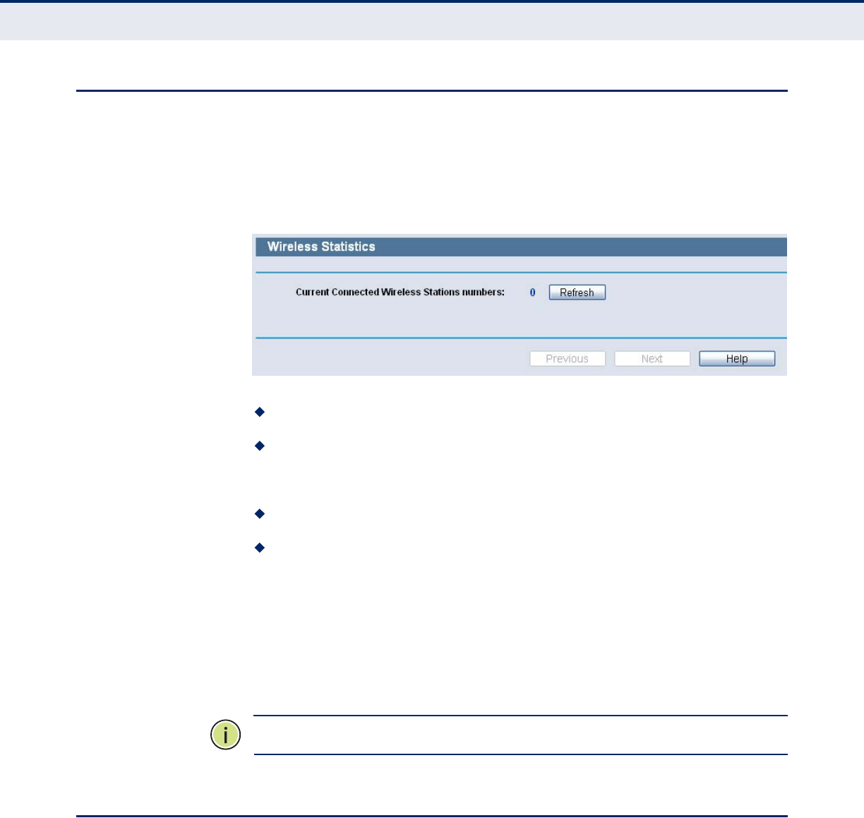
WIRELESS STATISTICS
Choose menu “Wireless->Wireless Statistics”, you can see the MAC
Address, Current Status, Received Packets and Sent Packets for each
connected wireless station.
Figure 43: Wireless Statistics
MAC Address - The connected wireless station's MAC address.
Current Status - The connected wireless station's running status, one
of STA-AUTH / STA-ASSOC / STA-JOINED / WPA / WPA-PSK / WPA2 /
WPA2-PSK / AP-UP / AP-DOWN / Disconnected.
Received Packets - Packets received by the station.
Sent Packets - Packets sent by the station.
You cannot change any of the values on this page. To update this page and
to show the current connected wireless stations, click on the Refresh
button.
If the numbers of connected wireless stations go beyond one page, click
the Next button to go to the next page and click the Previous button to
return the previous page.
N
OTE
:
This page will be refreshed automatically every 5 seconds.
WPS
This section will guide you add a new wireless device to an existing
network quickly by WPS (Wi-Fi Protected Setup) function.
1. Choose menu “WPS”, you will see the next screen.
C
HAPTER
6
| Wireless Settings
WPS
– 58 –
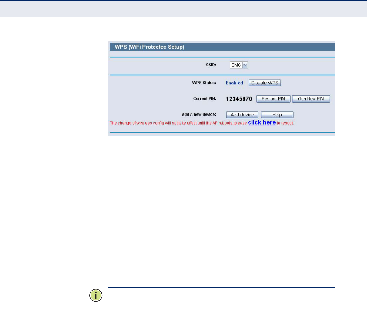
Figure 44: WPS
◆WPS Status - Enable or disable the WPS function here.
◆Current PIN - The current value of the Router's PIN displayed here.
The default PIN of the Router can be found in the label or User Guide.
◆Restore PIN - Restore the PIN of the Router to its default.
◆Gen New PIN - Click this button, and then you can get a new random
value for the Router's PIN. You can ensure the network security by
generating a new PIN.
◆Add device - You can add the new device to the existing network
manually by clicking this button.
2. Add a new device:
If the wireless adapter supports Wi-Fi Protected Setup (WPS), you can
establish a wireless connection between wireless adapter and Router using
either Push Button Configuration (PBC) method or PIN method.
N
OTE
:
To build a successful connection by WPS, you should also do the
corresponding configuration of the new device for WPS function
meanwhile.
For the configuration of the new device, here takes the Wireless Adapter of
our company for example.
By PBC:
If the wireless adapter supports Wi-Fi Protected Setup and the Push Button
Configuration (PBC) method, you can add it to the network by PBC with the
following two methods.
Method One:
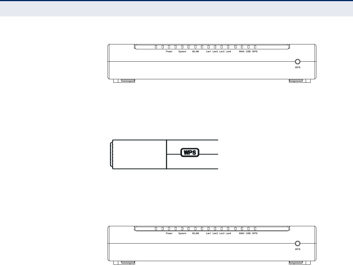
1. Press the WPS button on the front panel of the Router.
C
HAPTER
6
| Wireless Settings
WPS
– 59 –
Figure 45: WPS button
2. Press and hold the WPS button of the adapter directly for 2 or 3
seconds, then the adapter will connect to the router by WPS
automatically.
Figure 46: WPS button
Method Two:
1. Press the WPS button on the front panel of the Router.
Figure 47: WPS button
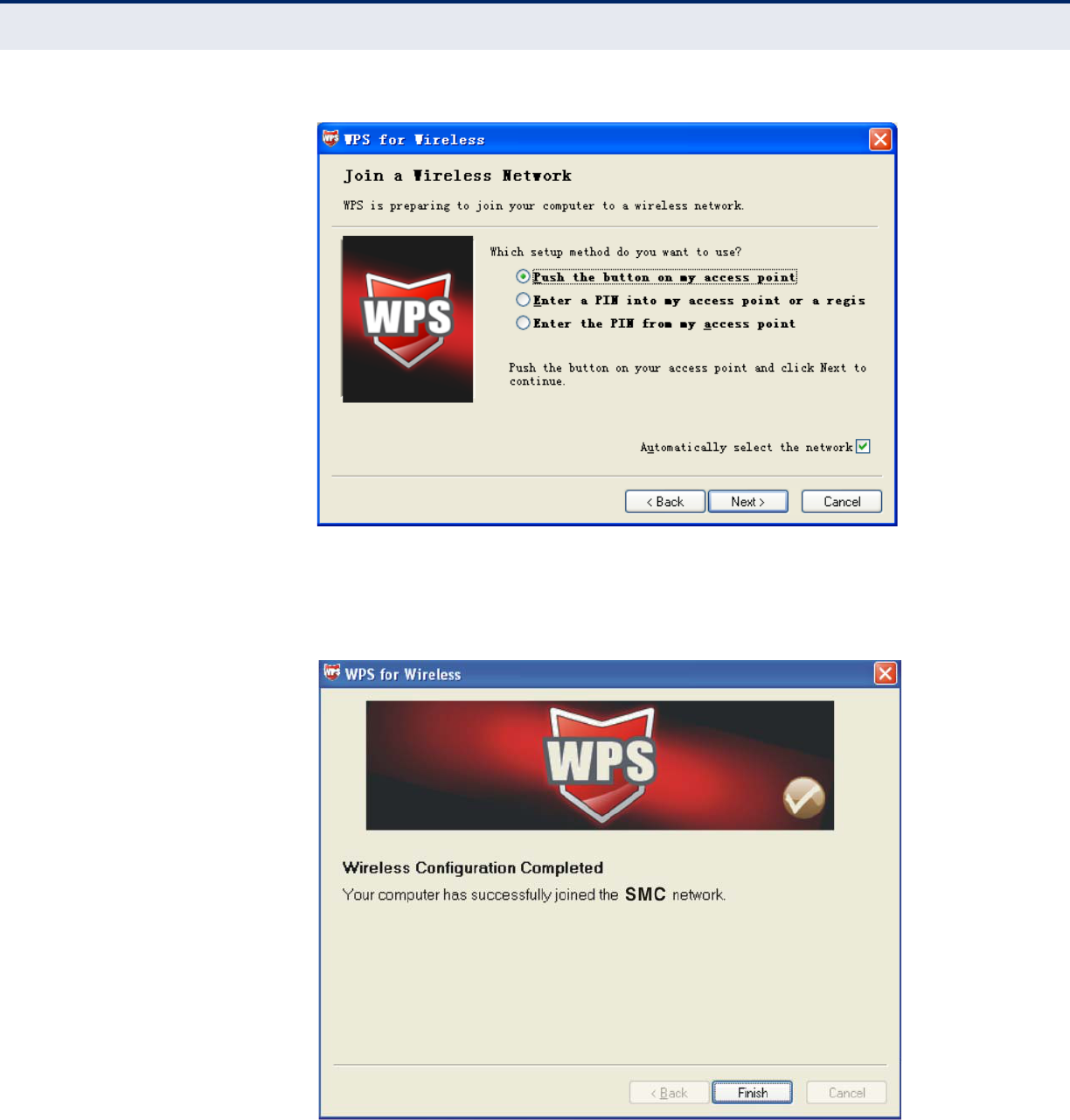
2. For the configuration of the wireless adapter, please choose Push the
button on my access point in the configuration utility of the WPS as
below, and click Next.
C
HAPTER
6
| Wireless Settings
WPS
– 60 –
Figure 48: The WPS Configuration Screen of Wireless Adapter
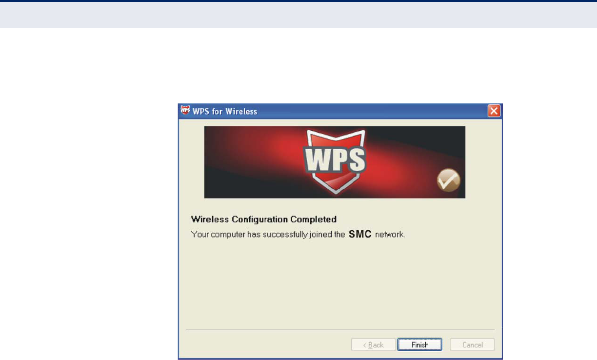
3. Wait for a while until the next screen appears. Click Finish to complete
the WPS configuration.
Figure 49: The WPS Configuration Screen of Wireless Adapter
C
HAPTER
6
| Wireless Settings
WPS
– 61 –
Method Three:
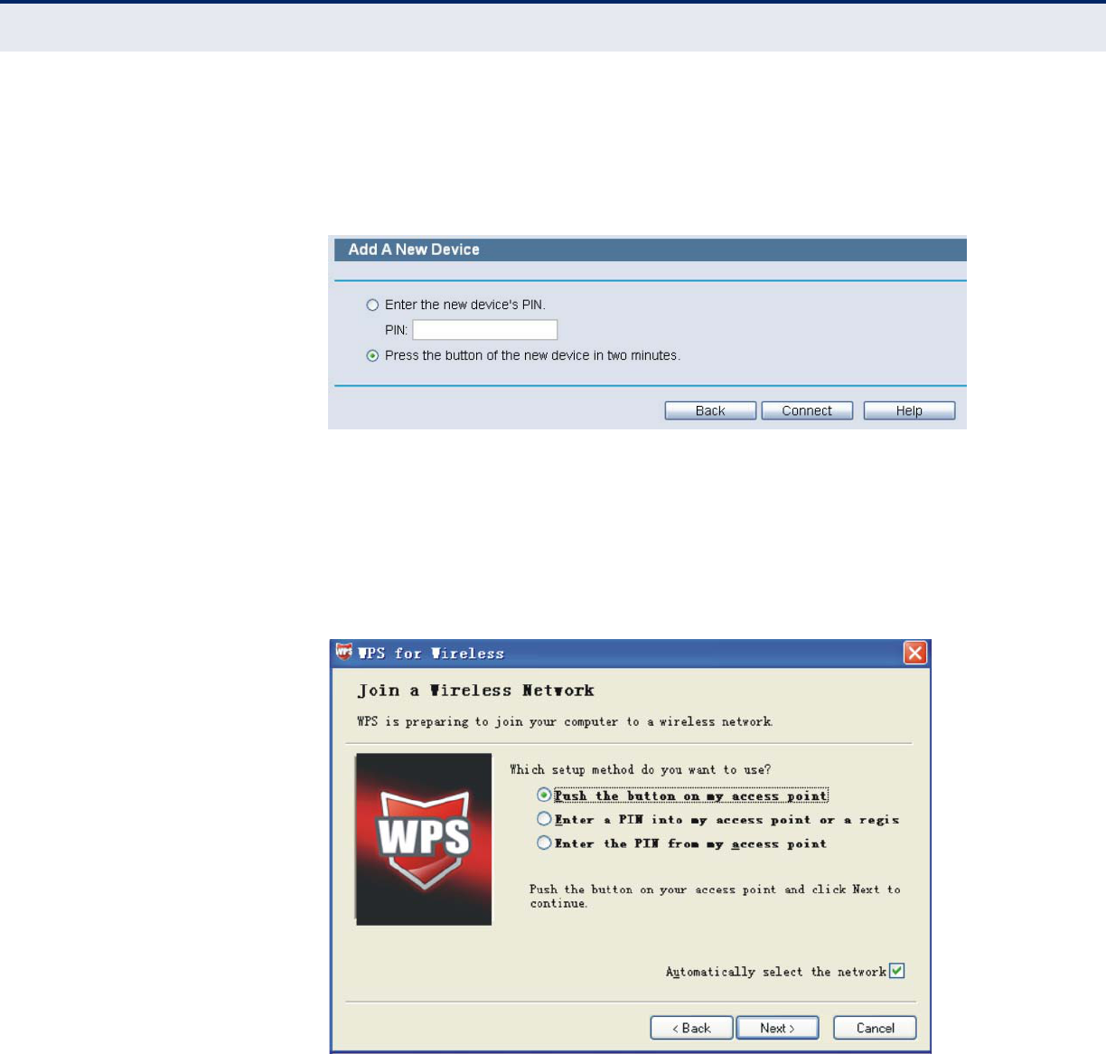
1. Keep the default WPS Status as Enabled and click the Add device
button in Figure 44, then the following screen will appear.
Figure 50: Add a New Device
2. Choose Press the button of the new device in two minutes and click
Connect.
3. For the configuration of the wireless adapter, please choose Push the
button on my access point in the configuration utility of the WPS as
below, and click Next.
Figure 51: The WPS Configuration Screen of Wireless Adapter
C
HAPTER
6
| Wireless Settings
WPS
– 62 –
4. Wait for a while until the next screen appears. Click Finish to complete
the WPS configuration.
Figure 52: The WPS Configuration Screen of Wireless Adapter
C
HAPTER
6
| Wireless Settings
WPS
– 63 –
By PIN
If the new device supports Wi-Fi Protected Setup and the PIN method, you
can add it to the network by PIN with the following two methods.
Method One: Enter the PIN into my Router
1. Keep the default WPS Status as Enabled and click the Add device
button in Figure 44, then the following screen will appear.
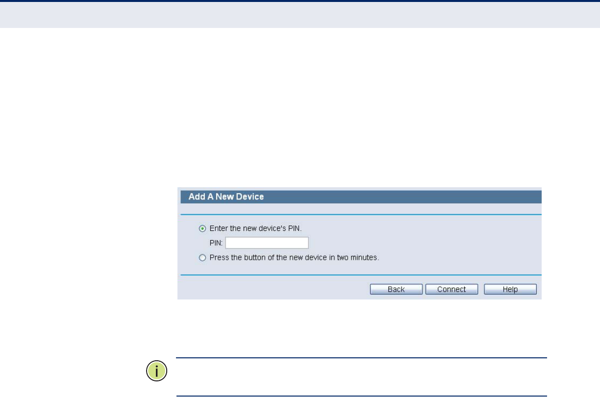
Figure 53: Add a New Device
2. Choose Enter the new device's PIN and enter the PIN code of the
wireless adapter in the field behind PIN in the above figure. Then click
Connect.
N
OTE
:
The PIN code of the adapter is always displayed on the WPS
configuration screen.
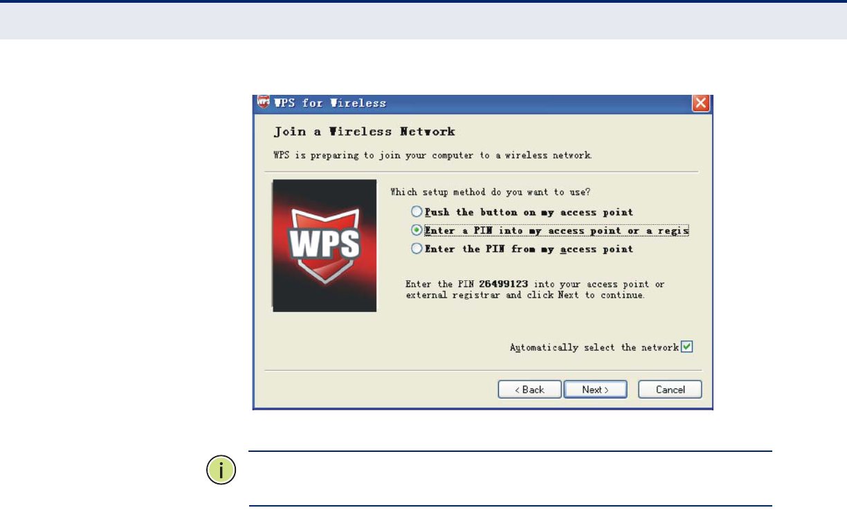
3. For the configuration of the wireless adapter, please choose Enter a PIN
into my access point or a registrar in the configuration utility of the
WPS as below, and click Next.
C
HAPTER
6
| Wireless Settings
WPS
– 64 –
Figure 54: The WPS Configuration Screen of Wireless Adapter
N
OTE
:
In this example, the default PIN code of this adapter is 26499123 as
the above figure shown.
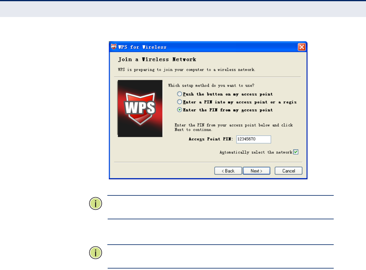
Method Two: Enter the PIN from my Router
1. Get the Current PIN code of the Router. (Each router has its unique PIN
code. Here takes the PIN code 12345670 of this Router for example).
2. For the configuration of the wireless adapter, please choose Enter a PIN
from my access point in the configuration utility of the WPS as below,
and enter the PIN code of the Router into the field behind Access Point
PIN. Then click Next.
C
HAPTER
6
| Wireless Settings
WPS
– 65 –
Figure 55: The WPS Configuration Screen of Wireless Adapter
N
OTE
:
The default PIN code of the Router can be found in its label or the
WPS configuration screen as Figure 44.
3. Then the new device successfully connected to the network.
N
OTE
:
The status LED on the Router will light green all the time if the
device has been successfully added to the network.
The WPS function cannot be configured if the Wireless Function of the
Router is disabled. Please make sure the Wireless Function is enabled
before configuring the WPS.
– 65 –
7DHCP SETTINGS
There are three submenus under the DHCP menu: DHCP Settings, DHCP
Clients List and Address Reservation. Click any of them, and you will be
able to configure the corresponding function.
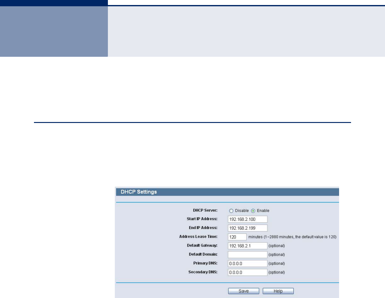
DHCP SETTINGS
Choose menu “DHCP->DHCP Settings”, you can configure the DHCP Server
on the page. The Router is set up by default as a DHCP (Dynamic Host
Configuration Protocol) server, which provides the TCP/IP configuration for
all the PC(s) that are connected to the Router on the LAN.
Figure 56: DHCP Settings
◆DHCP Server - Enable or Disable the DHCP server. If you disable the
Server, you must have another DHCP server within your network or else
you must configure the computer manually.
◆Start IP Address - Specify an IP address for the DHCP Server to start
with when assigning IP addresses. 192.168.2.100 is the default start
address.
◆End IP Address - Specify an IP address for the DHCP Server to end
with when assigning IP addresses. 192.168.2.199 is the default end
address.
C
HAPTER
7
| DHCP Settings
DHCP Clients List
– 66 –
◆Address Lease Time - The Address Lease Time is the amount of time
a network user will be allowed connection to the Router with their
current dynamic IP Address. Enter the amount of time in minutes and
the user will be "leased" this dynamic IP Address. After the time is up,
the user will be automatically assigned a new dynamic IP address. The
range of the time is 1 ~ 2880 minutes. The default value is 120
minutes.
◆Default Gateway - (Optional.) Suggest to input the IP address of the
LAN port of the Router, default value is 192.168.2.1
◆Default Domain - (Optional.) Input the domain name of your network.
◆Primary DNS - (Optional.) Input the DNS IP address provided by your
ISP. Or consult your ISP.
◆Secondary DNS - (Optional.) Input the IP address of another DNS
server if your ISP provides two DNS servers.
N
OTE
:
To use the DHCP server function of the Router, you must configure
all computers on the LAN as "Obtain an IP Address automatically" mode.
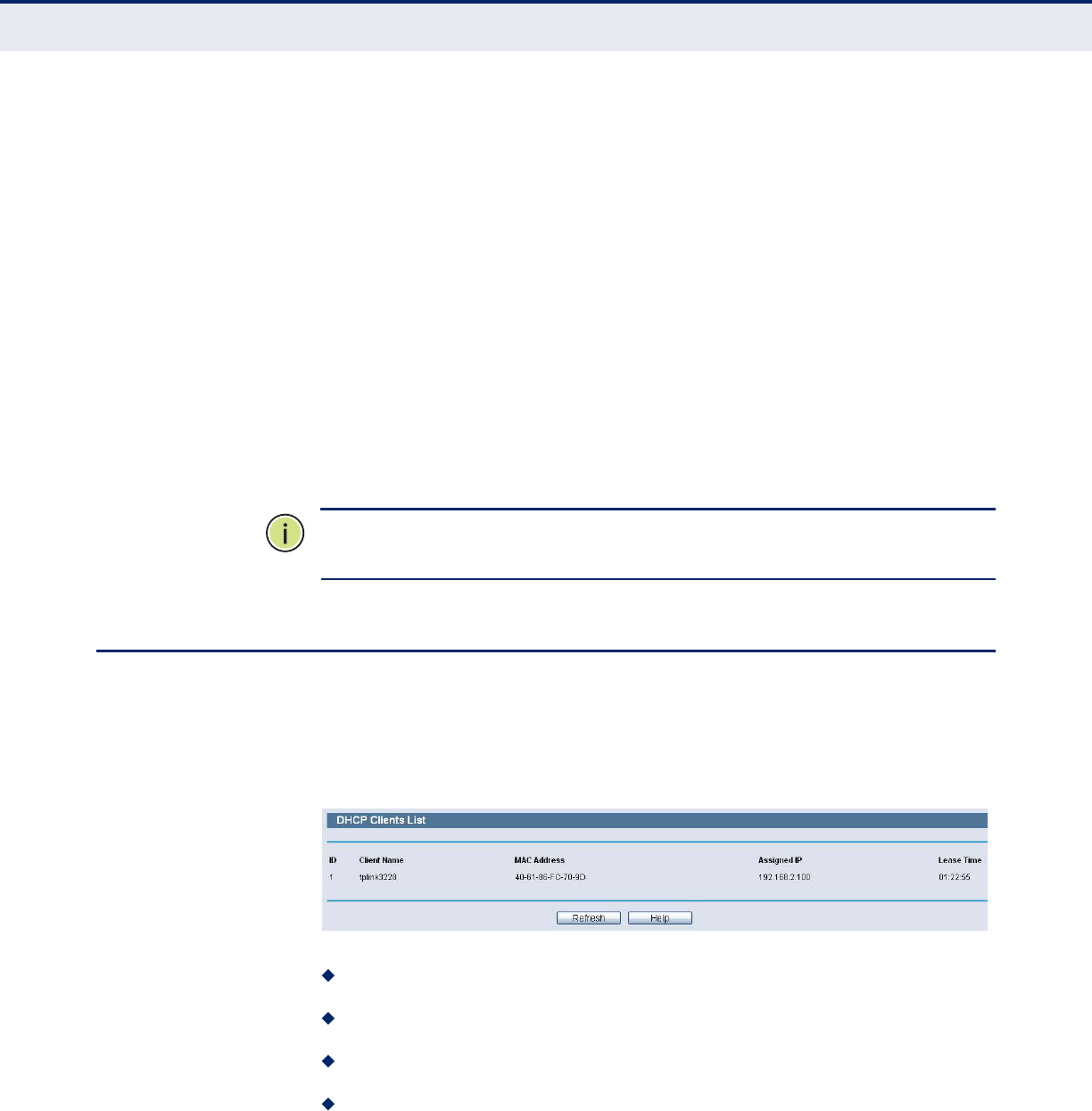
DHCP CLIENTS LIST
Choose menu “DHCP->DHCP Clients List”, you can view the information
about the clients attached to the Router in the following screen.
Figure 57: DHCP Client List
ID - The index of the DHCP Client
Client Name - The name of the DHCP client
MAC Address - The MAC address of the DHCP client
Assigned IP - The IP address that the Router has allocated to the
DHCP client.