Edimax Technology Co 9512050408 802.11g WIRELESS LAN USB PRINT SERVER / CONVERTER User Manual EW 7206Cg V1 MG02 TLS
Edimax Technology Co Ltd 802.11g WIRELESS LAN USB PRINT SERVER / CONVERTER EW 7206Cg V1 MG02 TLS
UserManual.wiki
>
Edimax Technology Co
>
9512050408 User Manual
USERS MANUAL
Navigation menu
Upload a User Manual
Namespaces
Wiki Guide
HTML
PDF
Info
Views
User Manual
Discussion / Help
Navigation

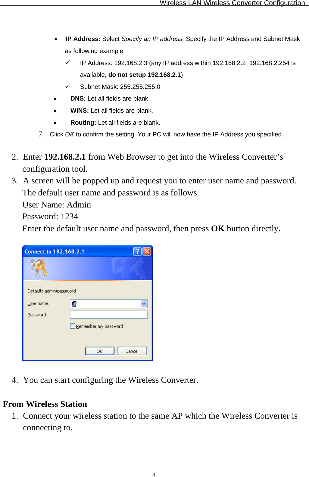
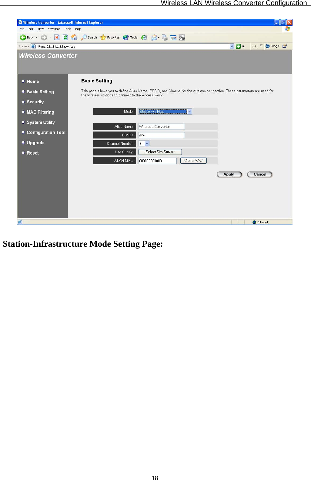
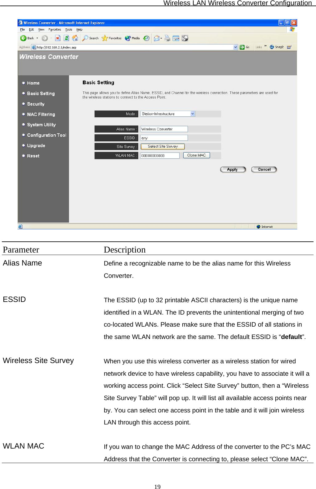
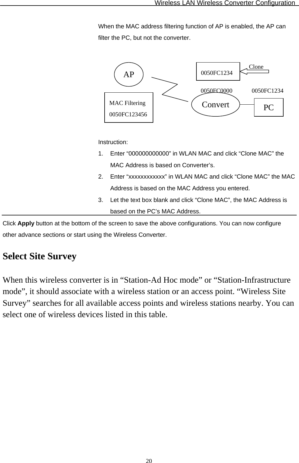
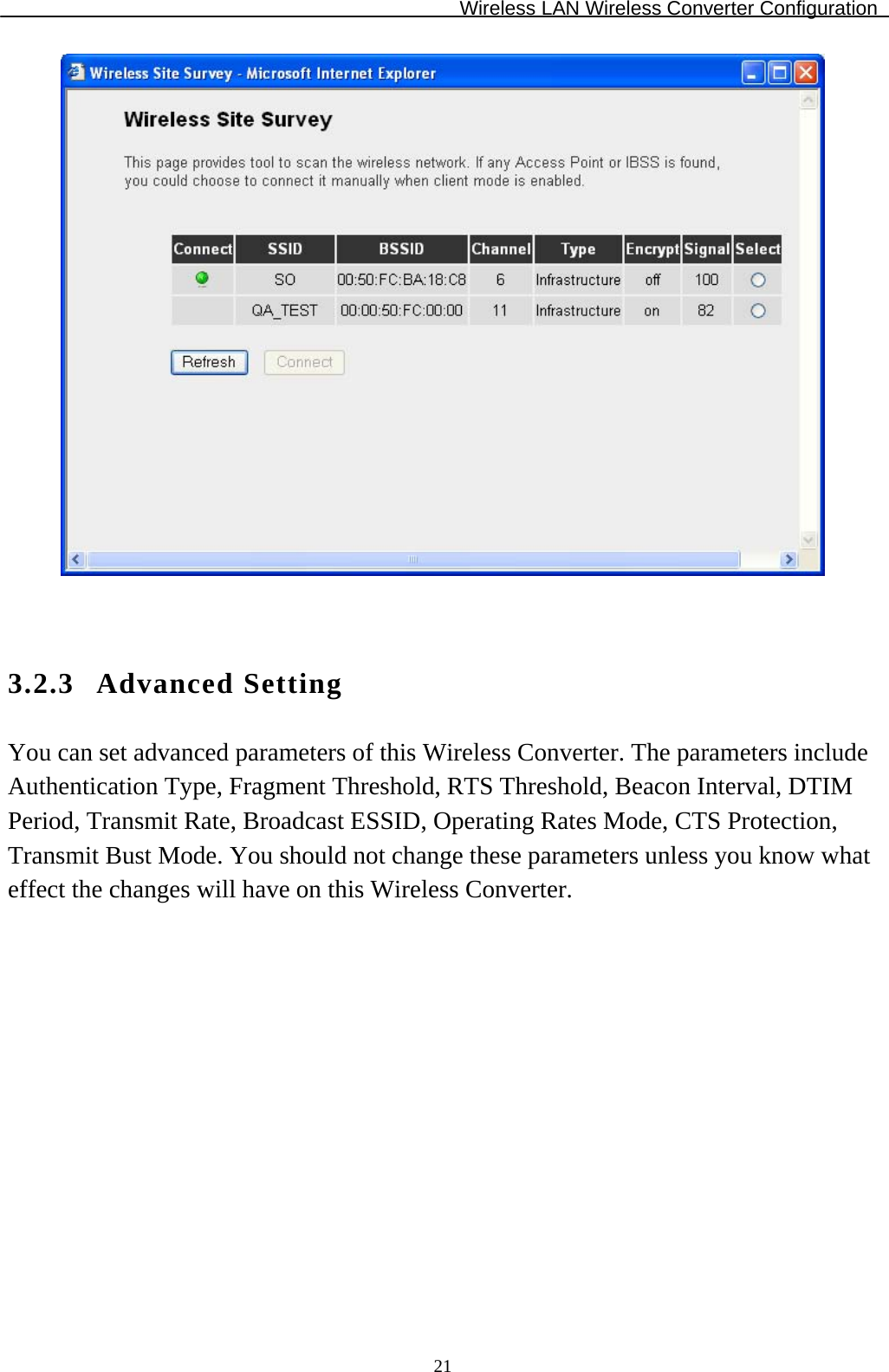
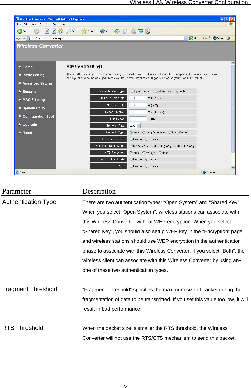
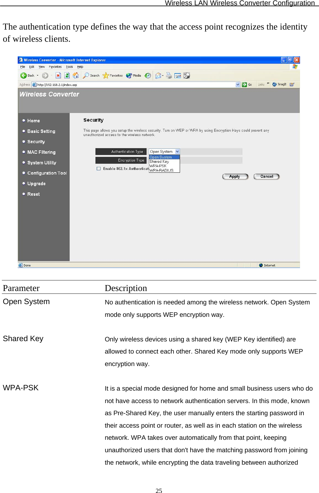
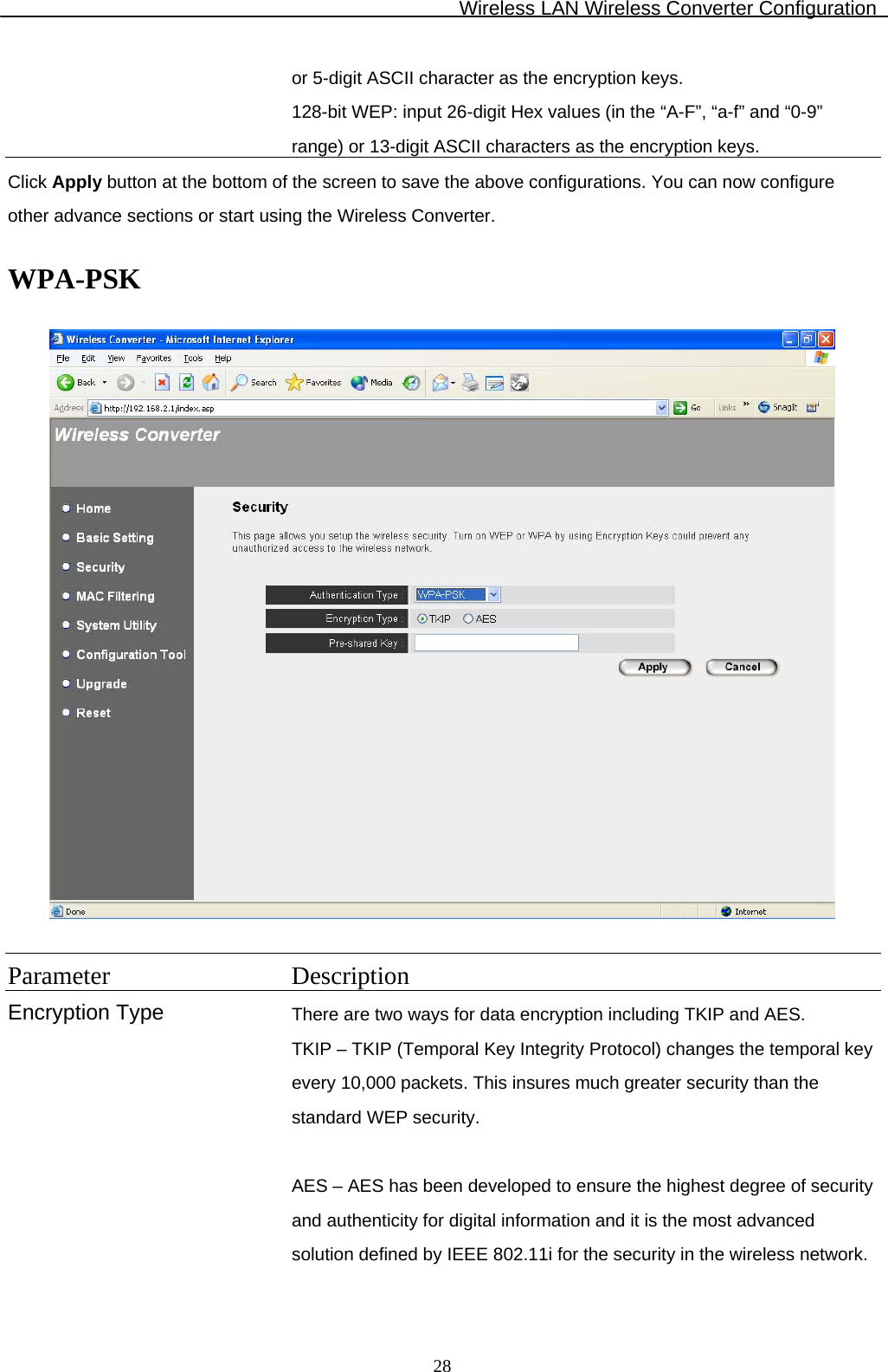
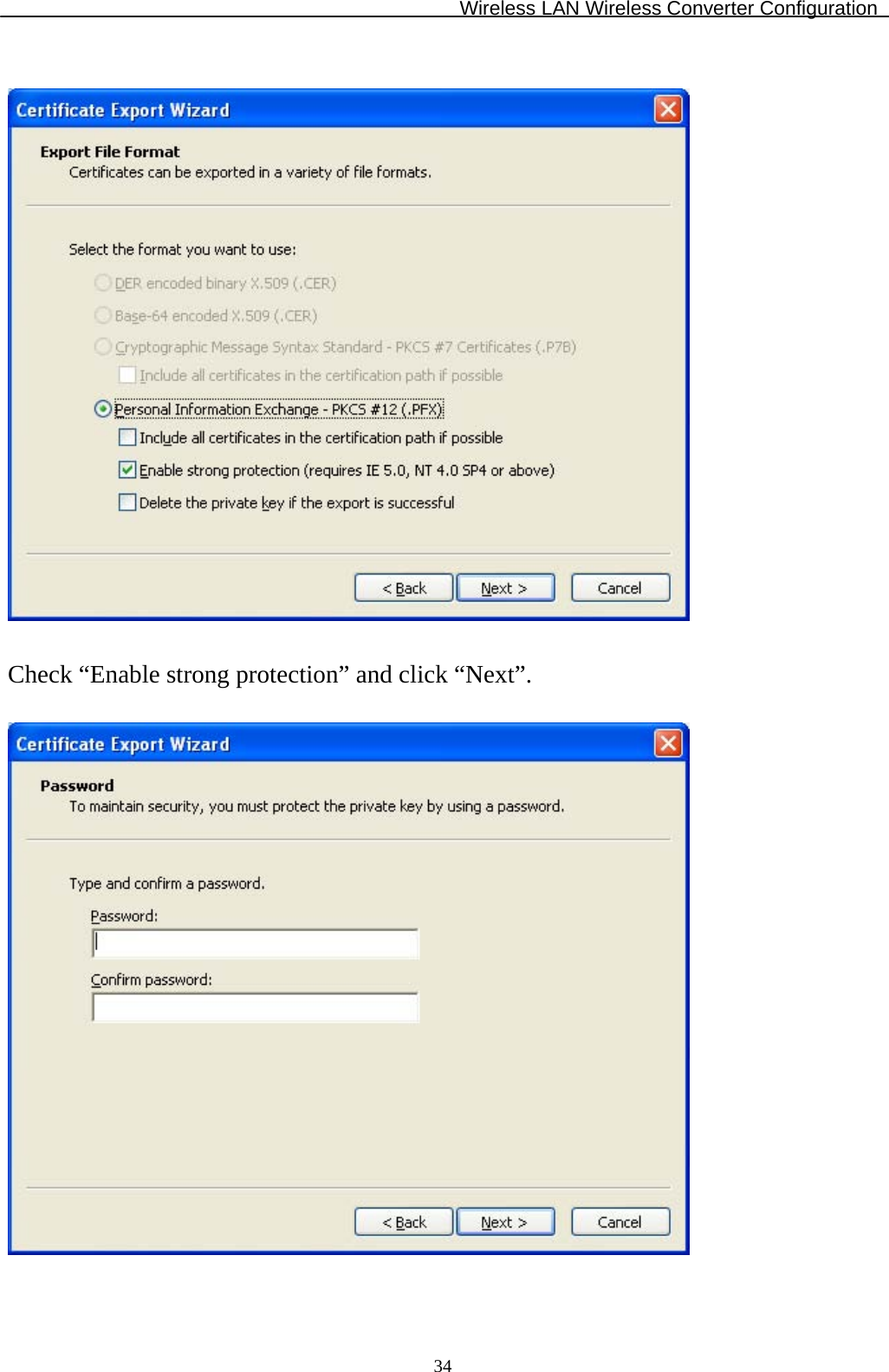
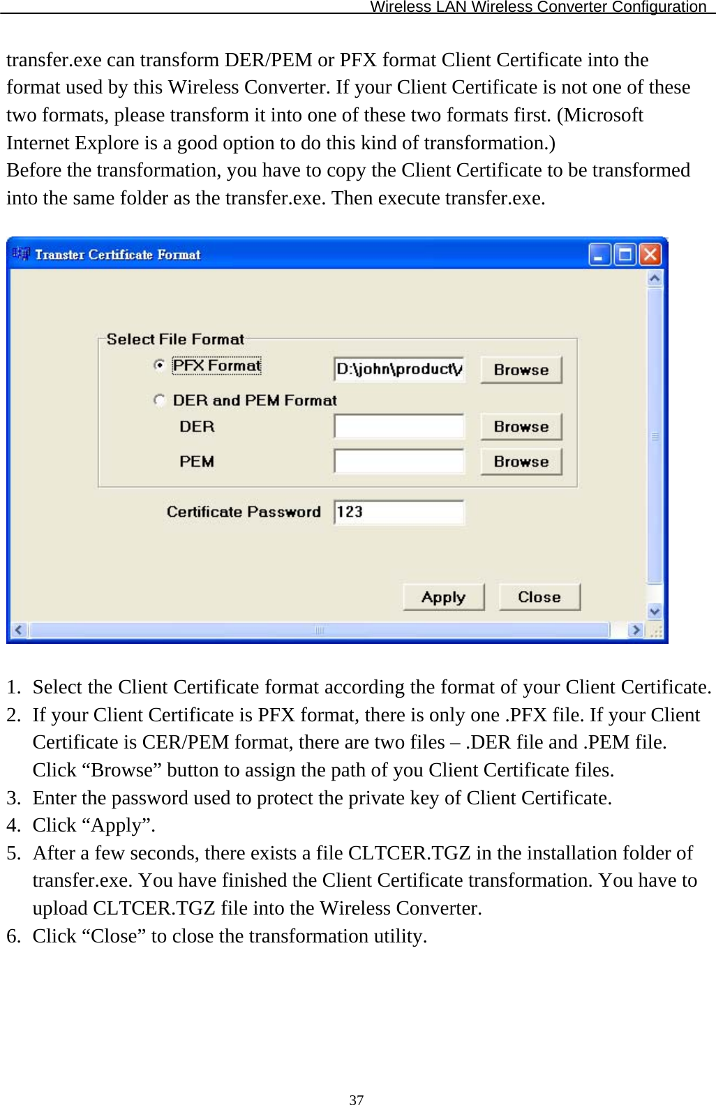
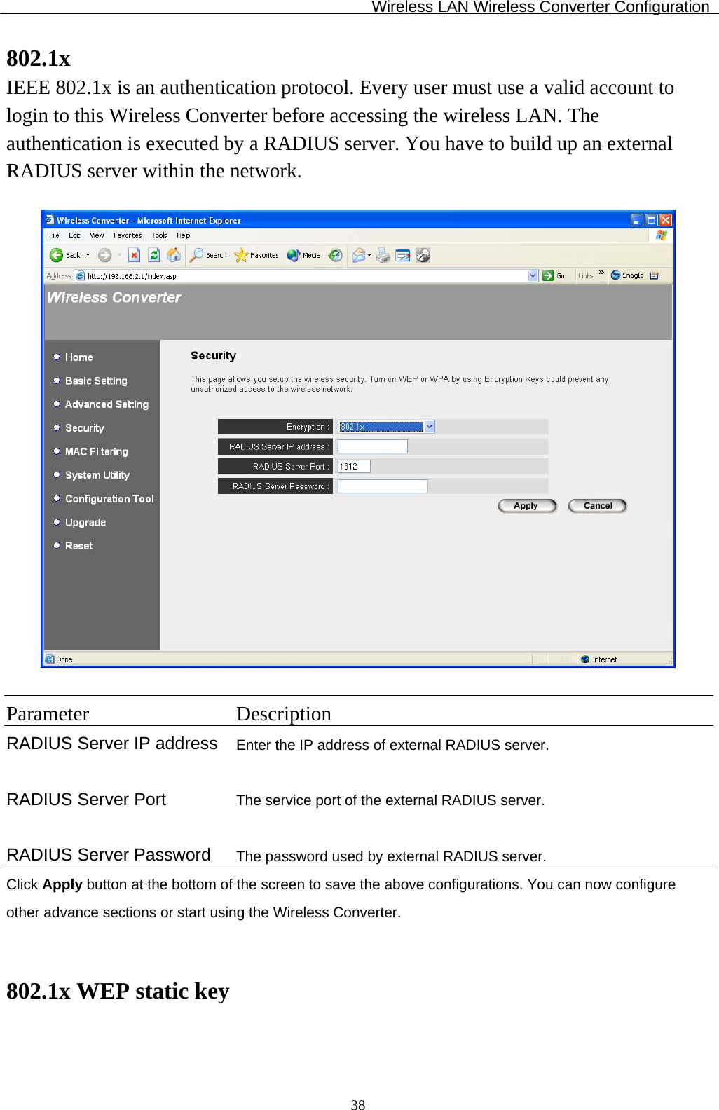
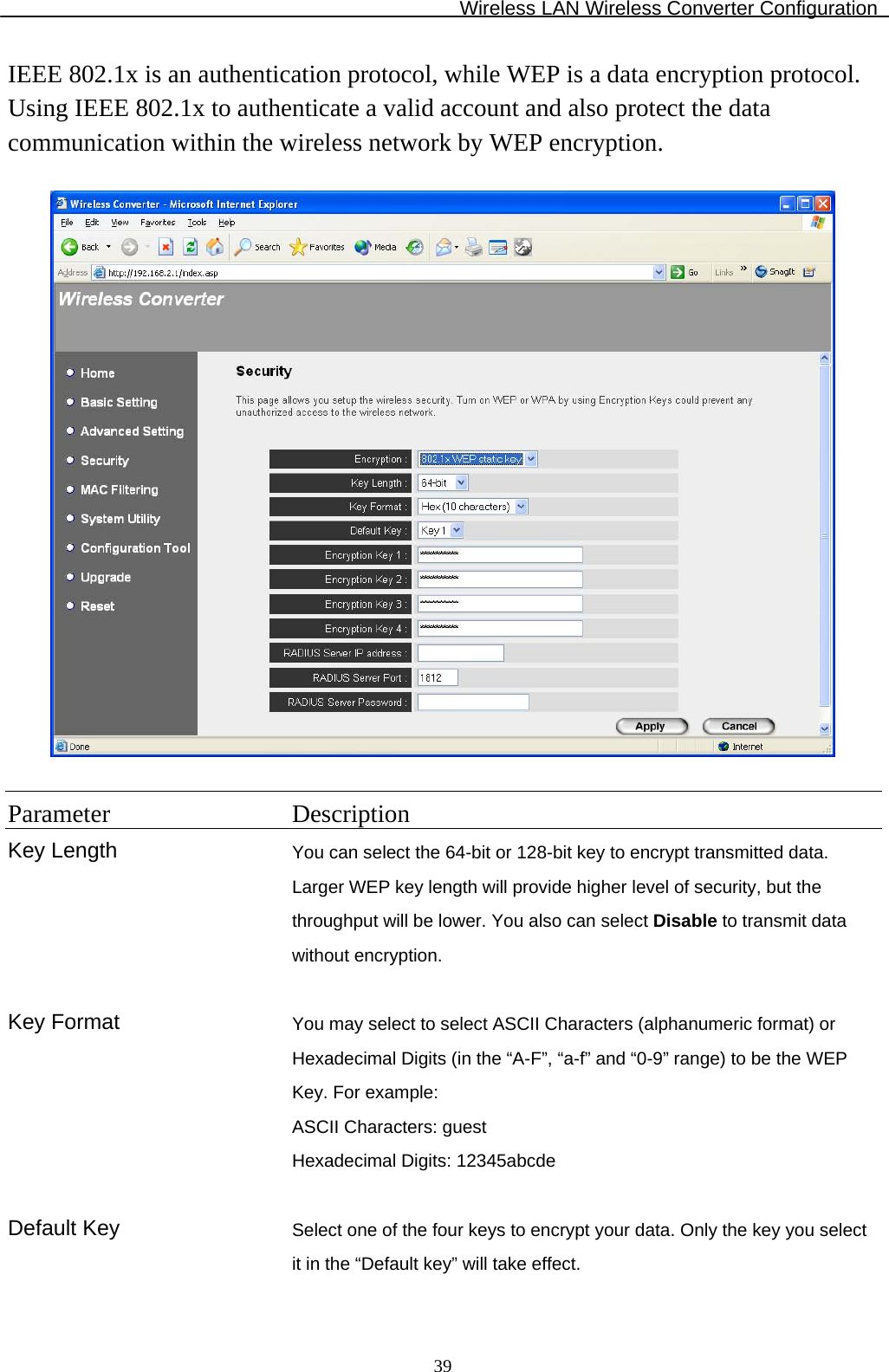
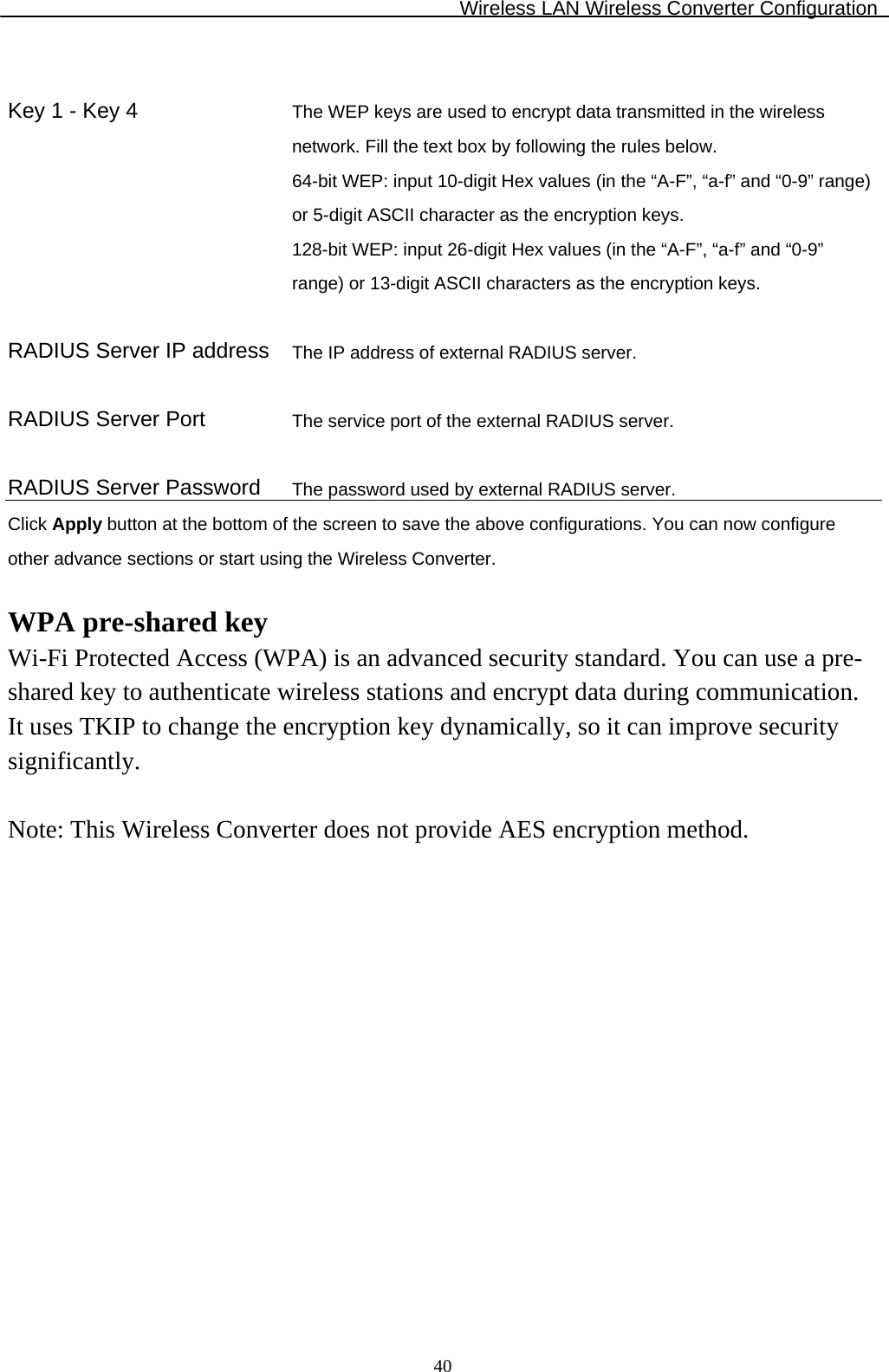
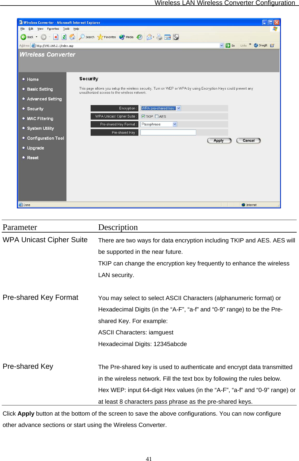
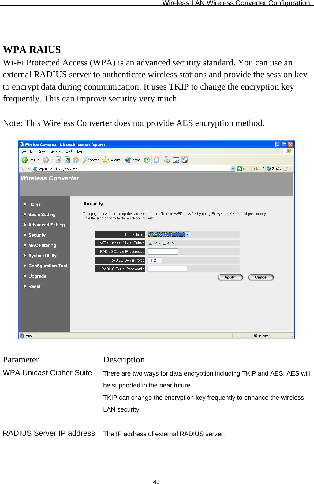
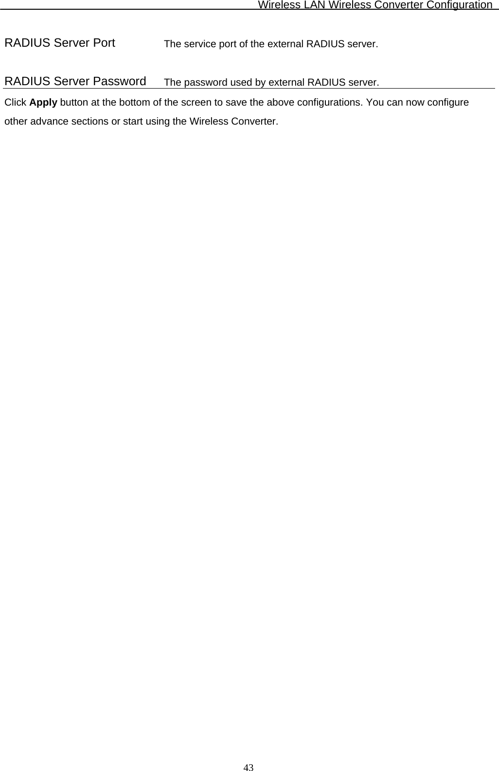
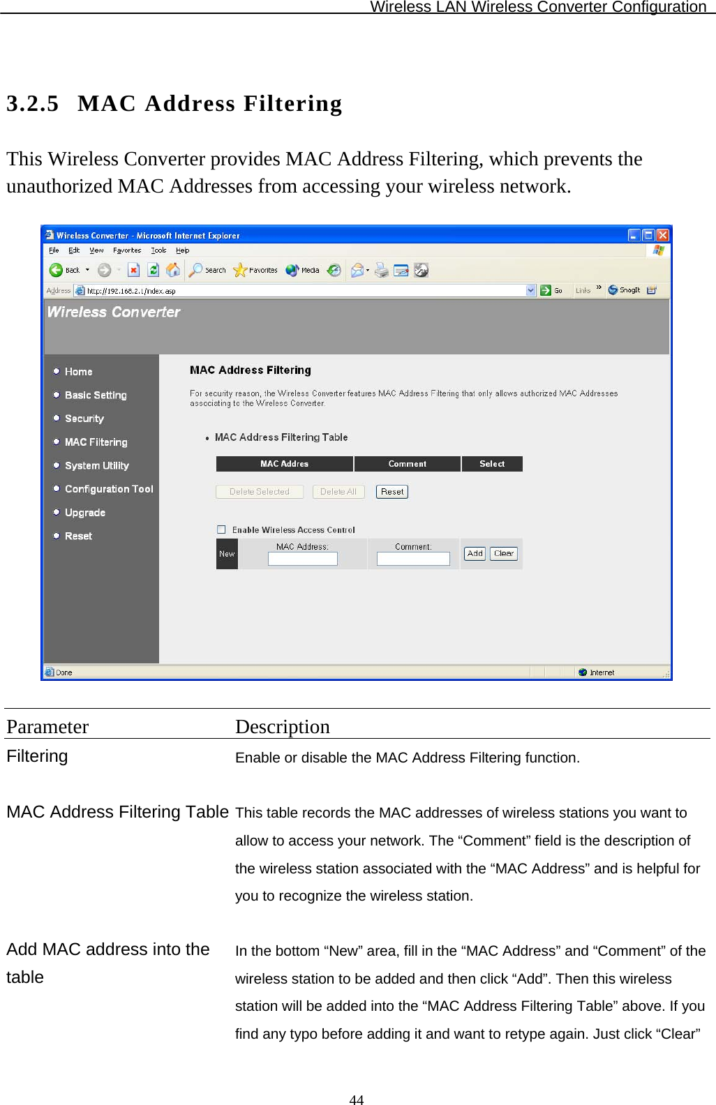
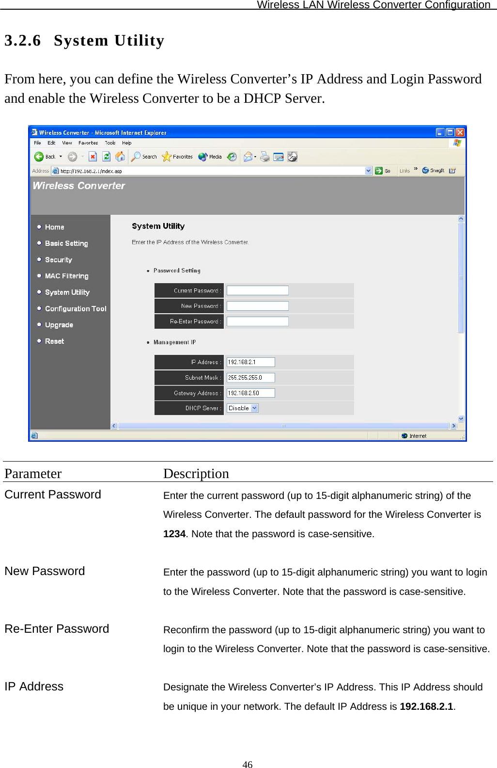
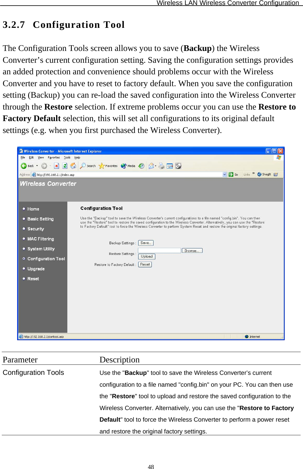
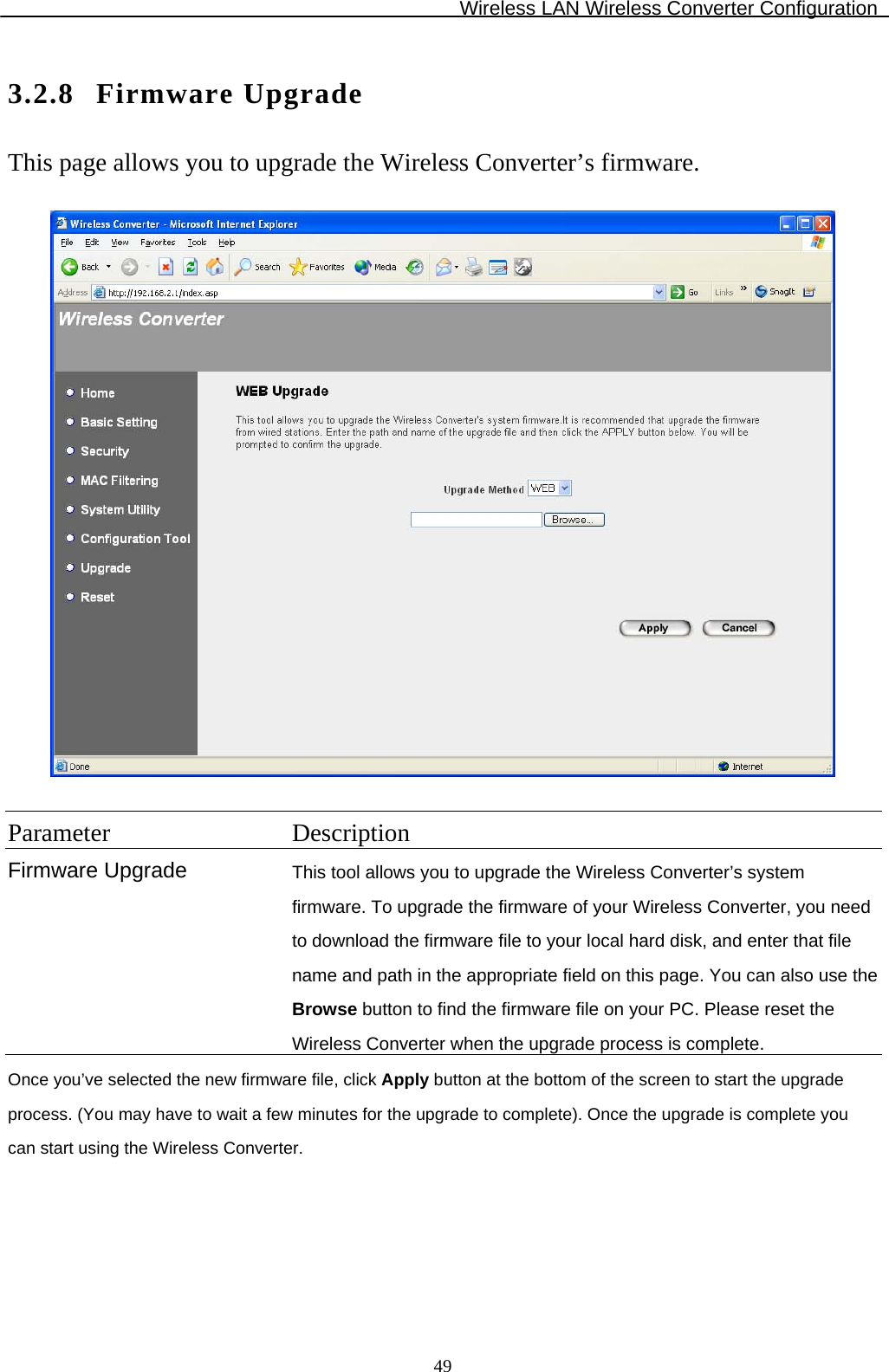
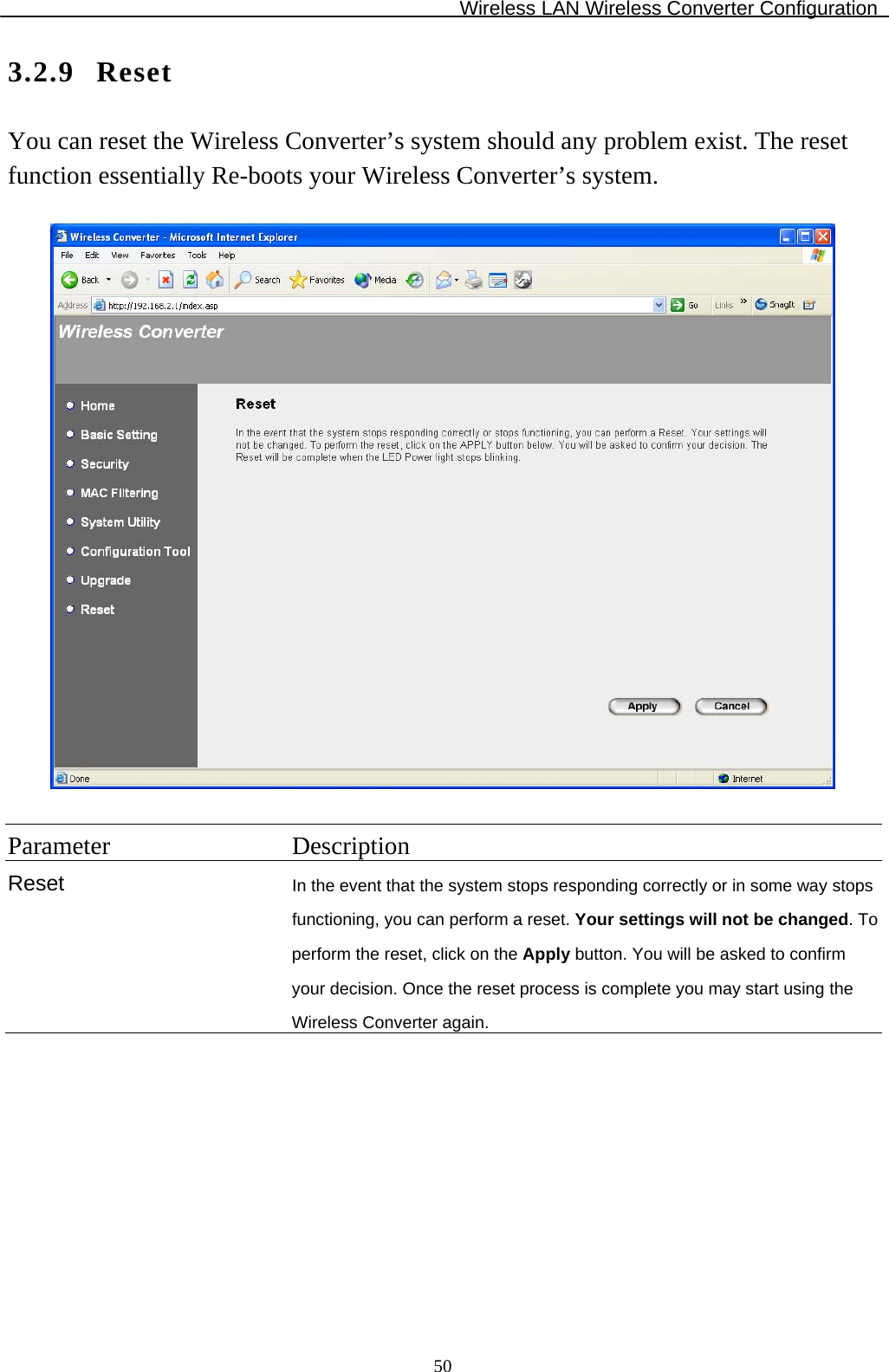
![Wireless LAN Wireless Converter Configuration 7 • IP Address: Select Specify an IP Address. Specify the IP Address and Subnet Mask as following example. IP Address: 192.168.2.3 (any IP address within 192.168.2.2~192.168.2.254 is available, do not setup 192.168.2.1) Subnet Mask: 255.255.255.0 8. Reboot the PC. Your PC will now have the IP Address you specified. 1b) Windows 2000 1. Click the Start button and select Settings, then click Control Panel. The Control Panel window will appear. 2. Double-click Network and Dial-up Connections icon. In the Network and Dial-up Connection window, double-click Local Area Connection icon. The Local Area Connection window will appear. 3. In the Local Area Connection window, click the Properties button. 4. Check your list of Network Components. You should see Internet Protocol [TCP/IP] on your list. Select it and click the Properties button. 5. In the Internet Protocol (TCP/IP) Properties window, select Use the following IP address and specify the IP Address and Subnet mask as following. IP Address: 192.168.2.3 (any IP address within 192.168.2.2~192.168.2.254 is available, do not setup 192.168.2.1) Subnet Mask: 255.255.255.0 6. Click OK to confirm the setting. Your PC will now have the IP Address you specified. 1c) Windows NT 1. Click the Start button and select Settings, then click Control Panel. The Control Panel window will appear. 2. Double-click Network icon. The Network window will appear. Select the Protocol tab from the Network window. 3. Check if the TCP/IP Protocol is on your list of Network Protocols. If TCP/IP is not installed, click the Add button to install it now. If TCP/IP is installed, go to step 5. 4. In the Select Network Protocol window, select the TCP/IP Protocol and click the Ok button to start installing the TCP/IP protocol. You may need your Windows CD to complete the installation. 5. After you install TCP/IP, go back to the Network window. Select TCP/IP from the list of Network Protocols and then click the Properties button. 6. Check each of the tabs and verify the following settings:](https://usermanual.wiki/Edimax-Technology-Co/9512050408/User-Guide-486507-Page-9.png)