Edimax Technology Co 9530111503 Door Watcher Internet Camera User Manual
Edimax Technology Co Ltd Door Watcher Internet Camera
User Manual
IC-3011DP
Quick Installation Guide
(QIG)
V1.0
2015-11
2
Table of Contents
I. Product Information .............................................................................. 3
I-1. Package Content ..................................................................................................................... 3
I-2. LED Status(Gateway)............................................................................................................... 3
I-3. LED Status(Camera) ................................................................................................................ 4
I-4. Pairing ..................................................................................................................................... 5
I-5. Reset ....................................................................................................................................... 6
II. Gateway Installation ............................................................................. 7
III. Camera Installation ............................................................................ 8-9
IV. Camera Setup – Using Mobile APP ................................................... 10-11
V. Camera Setup – Mobile APP Instruction ................................................ 12
VI. FCC Statement ..................................................................................... 13
3
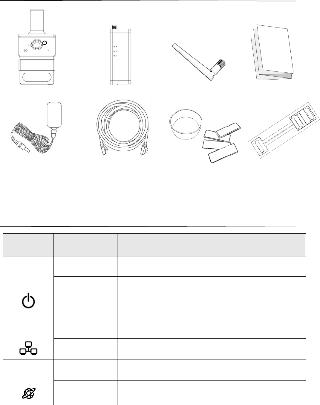
Package Contents
LED Status(Gateway)
LED Color LED Status Description
Green
Quick Flashing Paired camera data has been cleared.
Quick Flashing The gateway is restarting.
Slow Flashing Pairing is activating.
Green On
The gateway is connected to the local
network.
Quick Flashing
The gateway is transferring data.
Orange
On The gateway is connecting to internet.
Slow Flashing The gateway is not connected to internet.
Antenna
Camera
Gateway
Hook
Template
QIG
Power
Adapter
Ethernet
Cable
Velcro &
Silicon Band
4
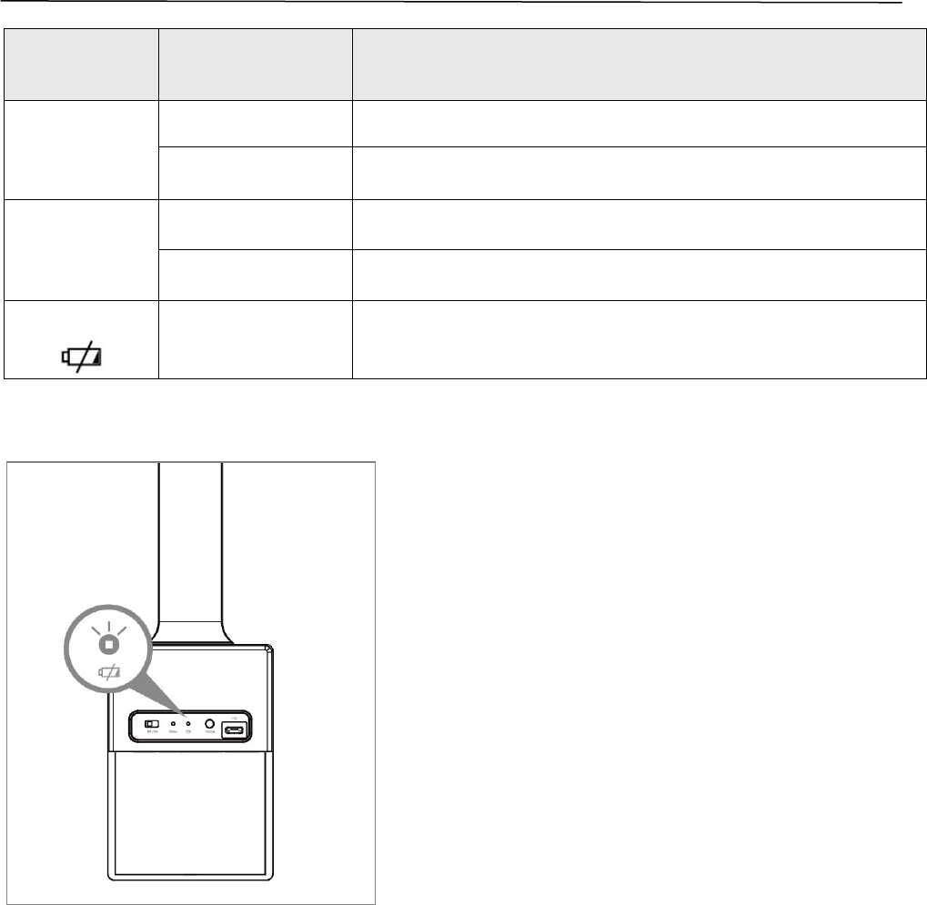
LED Status(Camera)
LED Color LED Status Description
Green
(Status)
On The camera is in use.
Slow Flashing Pairing is activating.
Orange
(Status)
Quick Flashing Success pairing (Blinks for 5 seconds).
Slow Flashing PIR event trigger.
Red
Slow Flashing Battery low power warning.(Figure 1)
(Figure 1, Battery low power indication)
5
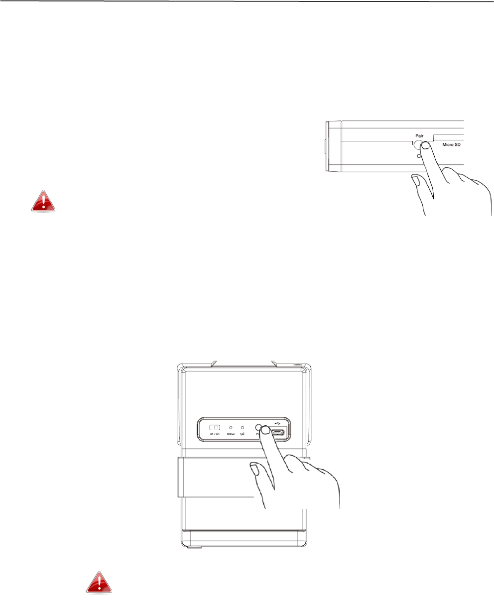
Pairing
The “Pair” button is a quick and easy alternative to establish a secure wireless
connection between your camera and gateway.
1. Press and hold the Pair button on your gateway for 2 seconds to activate
pairing.
The pair button for gateway
- Hold 2-4 seconds for pairing to activate.
- Hold more than 5 seconds to clean all paired camera data.
2. Within 30 seconds, press the “Pair” button on the camera for 1 – 2
seconds to activate pairing. The Status LED will flash quickly into “orange”
which indicates that pairing is successful.
One gateway can pair up to 4 cameras.
6
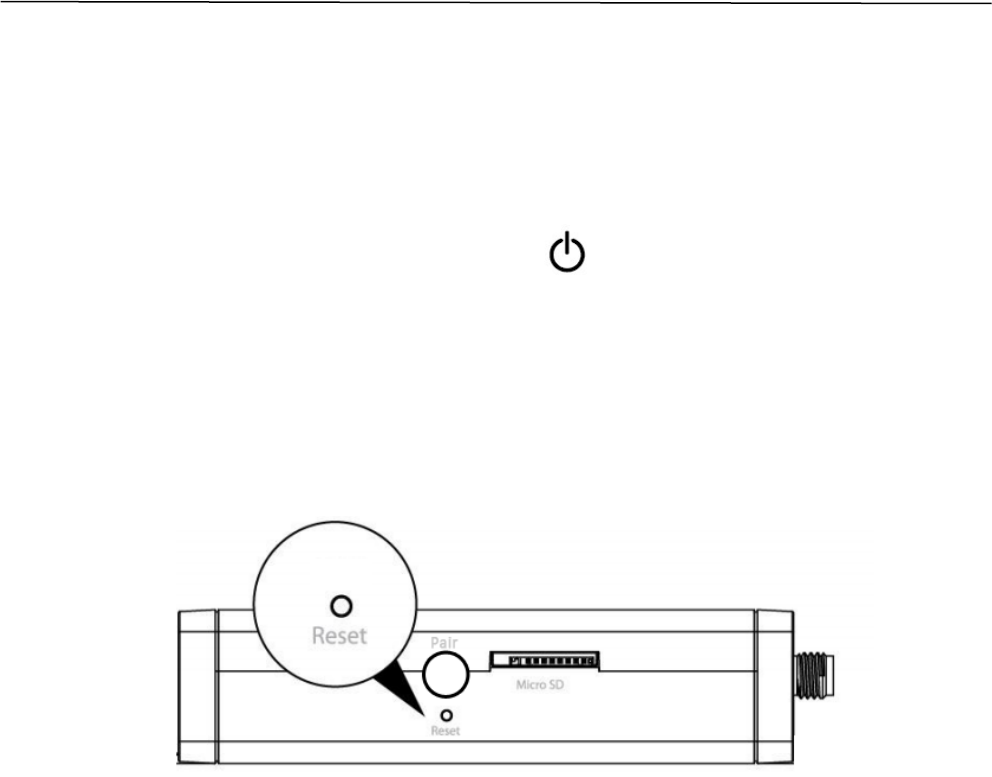
Reset
If you experience problems with your network camera, you can reset the
camera back to its factory default settings. This resets all settings back to
default.
1. Press and hold the Reset button found on the back panel for at least 10
seconds. Release the button when the …LED is flashing quickly into
“green”.
2. Wait for the gateway to restart.
7
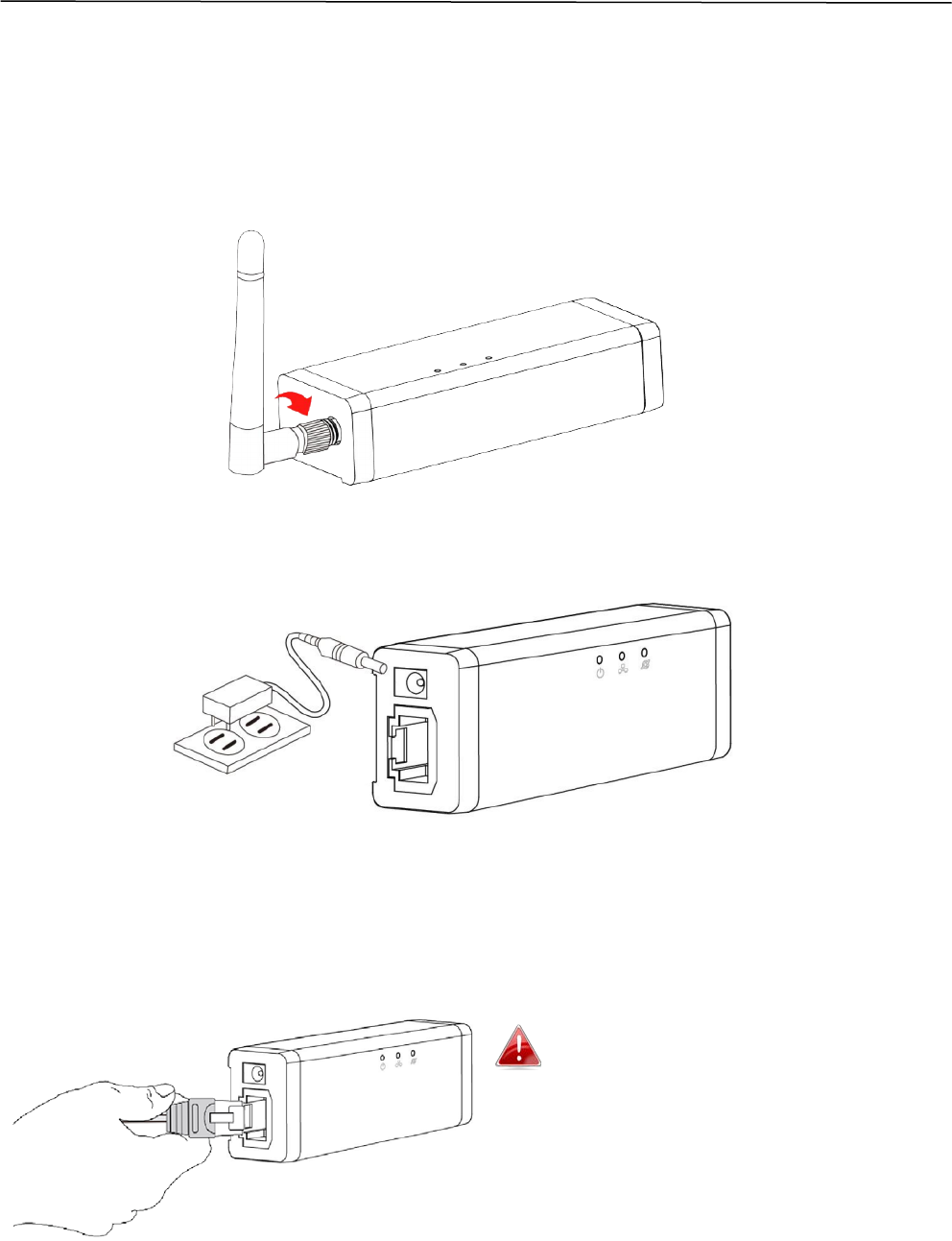
Gateway Installation
Follow the instructions below to ensure your camera is properly connected
and ready for setup.
1. Screw on the included antenna to the product’s gateway unit.
2. Connect the power adapter to the gateway and to a power supply.
3. Use an Ethernet cable to connect the gateway’s LAN port to a Wireless
AP/ Router’s LAN port, as shown below.
4. Wait a moment for the camera to power on. The camera is ready when
the Power LED of the camera displays on or flashing. Please refer to
Gateway LED Status on Page.3.
For cloud service, ensure your
Wireless AP/ Router can access to the
internet.
8
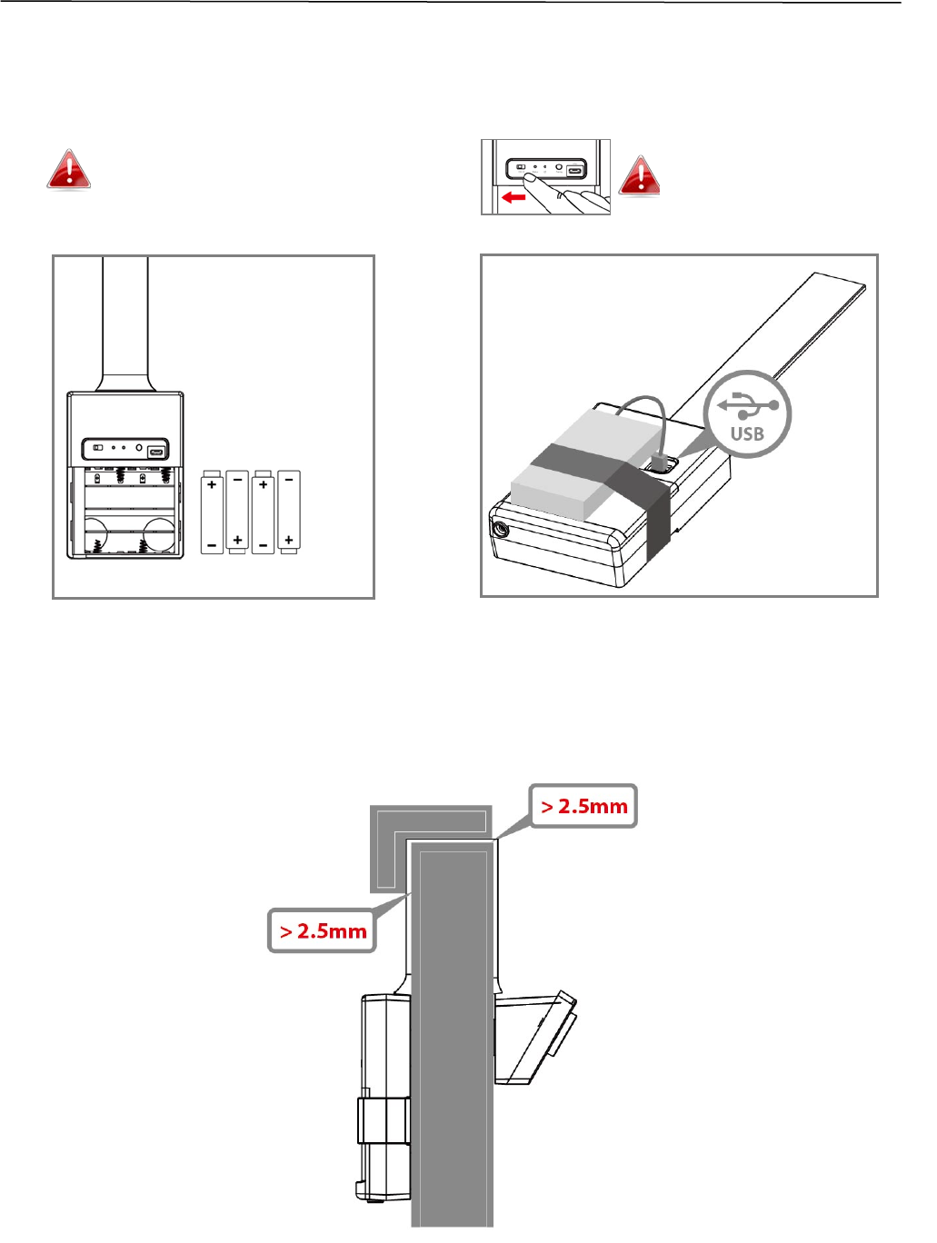
Camera Installation
1. For camera power supply, you can choose battery powered or USB power
bank, as shown below.(Figure A and Figure B)
2. The door gap must be more than 2.5mm as shown below.
(Figure A, Battery installation) (Figure B, USB Power bank installation)
For better performance, please use
Alkaline/rechargeable batteries.
(Heavy duty is not recommended!)
Please turn the switch “off”
before plugging the USB
power source.
9
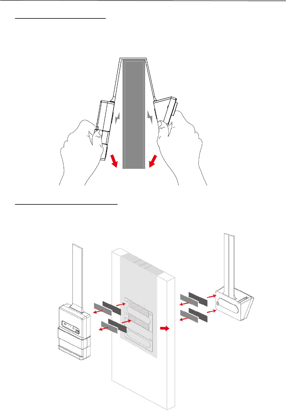
Camera Installation
3. Hook on the metal door.
With 5 strong magnets, you can easily install and adjust on a metal door
without any tools.
4. Hook on the nonmetal door
Fix and stick with the “Hook Template” and the “Velcro” on the nonmetal
door as shown below for the “assembling diagram”.
10
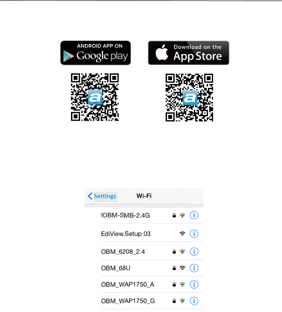
Camera Setup – Using Mobile App
1. Use a smartphone or tablet to search, download and install the
AcelinkView II app from Google Play or the Apple App Store.
2. For iOS/Android users, go to Wi-Fi settings and connect to your Wireless
AP/ Router’s SSID (ensure the camera gateway connected via LAN, see
Step.3 on Page.7), before opening the AcelinkView II app.
11
Camera Setup – Using Mobile App
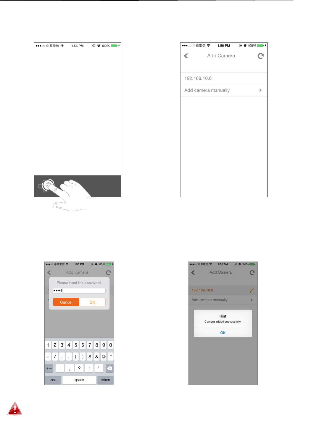
3. First time running the APP, click “+” icon to add camera (Figure C) and you
will see the camera IP address on the list which has connected on your local
network(Figure D).
4. Enter the password (The default password is 1234), it will pop up a
message if added successfully, as shown below.
(Figure C, add camera) (Figure D, camera list)
Reminder: Outdoor and other area where the camera is exposed to special lighting will have
some color shifting. This image is very common and perfectly normal. It’s due to the special
design of our camera lens.
12
Camera Setup –Mobile App Instruction
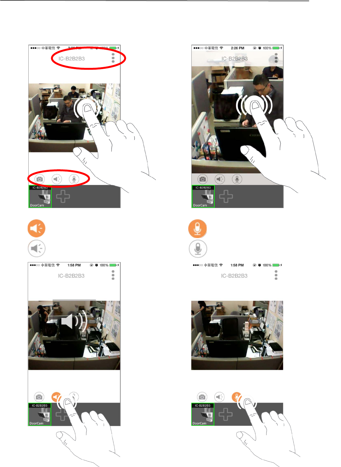
1. Single click : Show/Hide quick buttons, camera name and other settings.
Double click : Zoom in/ out video image.
2.
Camera Mic On(Hear from the Camera)
Camera Mic Off
Camera Speaker On (Talk to the Camera)
Camera Speaker Off
13
Federal Communication Commission Interference Statement
This equipment has been tested and found to comply with the limits for a Class B digital device, pursuant to Part
15 of FCC Rules. These limits are designed to provide reasonable protection against harmful interference in a
residential installation. This equipment generates, uses, and can radiate radio frequency energy and, if not
installed and used in accordance with the instructions, may cause harmful interference to radio communications.
However, there is no guarantee that interference will not occur in a particular installation. If this equipment does
cause harmful interference to radio or television reception, which can be determined by turning the equipment
off and on, the user is encouraged to try to correct the interference by one or more of the following measures:
1. Reorient or relocate the receiving antenna.
2. Increase the separation between the equipment and receiver.
3. Connect the equipment into an outlet on a circuit different from that to which the receiver is connected.
4. Consult the dealer or an experienced radio technician for help.
FCC Caution
Any changes or modifications not expressly approved by the party responsible for compliance could void the
authority to operate equipment.
This device complies with Part 15 of the FCC Rules. Operation is subject to the following two conditions: (1) this
device may not cause harmful interference, and (2) this device must accept any interference received, including
interference that may cause undesired operation.
FCC Radiation Exposure Statement:
This equipment complies with FCC radiation exposure limits set forth for an uncontrolled environment. This
equipment should be installed and operated with minimum distance 20cm between the radiator & your body.
This device and its antenna(s) must not be co-located or operating in conjunction with any other antenna or
transmitter.
R&TTE Compliance Statement
This equipment complies with all the requirements of DIRECTIVE 1999/5/EC OF THE EUROPEAN PARLIAMENT AND
THE COUNCIL of March 9, 1999 on radio equipment and telecommunication terminal equipment and the mutual
recognition of their conformity (R&TTE). The R&TTE Directive repeals and replaces in the directive 98/13/EEC
(Telecommunications Terminal Equipment and Satellite Earth Station Equipment) As of April 8, 2000.
Safety
This equipment is designed with the utmost care for the safety of those who install and use it. However, special
attention must be paid to the dangers of electric shock and static electricity when working with electrical
equipment. All guidelines of this and of the computer manufacture must therefore be allowed at all times to
ensure the safe use of the equipment.
EU Countries Intended for Use
The ETSI version of this device is intended for home and office use in Austria, Belgium, Bulgaria, Cyprus, Czech,
Denmark, Estonia, Finland, France, Germany, Greece, Hungary, Ireland, Italy, Latvia, Lithuania, Luxembourg, Malta,
Netherlands, Poland, Portugal, Romania, Slovakia, Slovenia, Spain, Sweden, Turkey, and United Kingdom. The ETSI
version of this device is also authorized for use in EFTA member states: Iceland, Liechtenstein, Norway, and
Switzerland.
EU Countries Not Intended for Use
None