Edimax Technology Co 9561040401 WIRELESS BROADBAND ROUTER User Manual BR 6104WB Manual
Edimax Technology Co Ltd WIRELESS BROADBAND ROUTER BR 6104WB Manual
UserManual.wiki
>
Edimax Technology Co
>
9561040401 User Manual
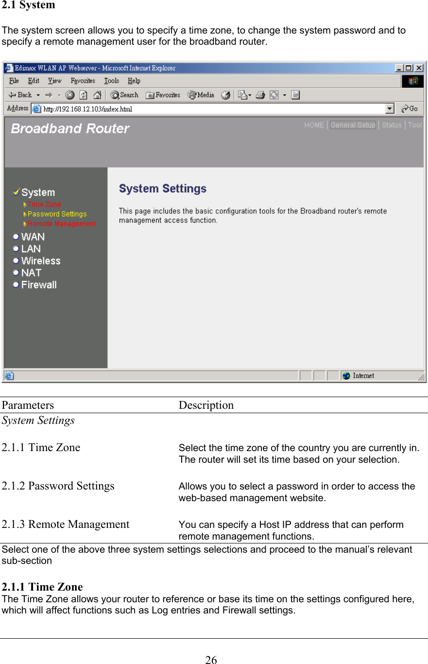
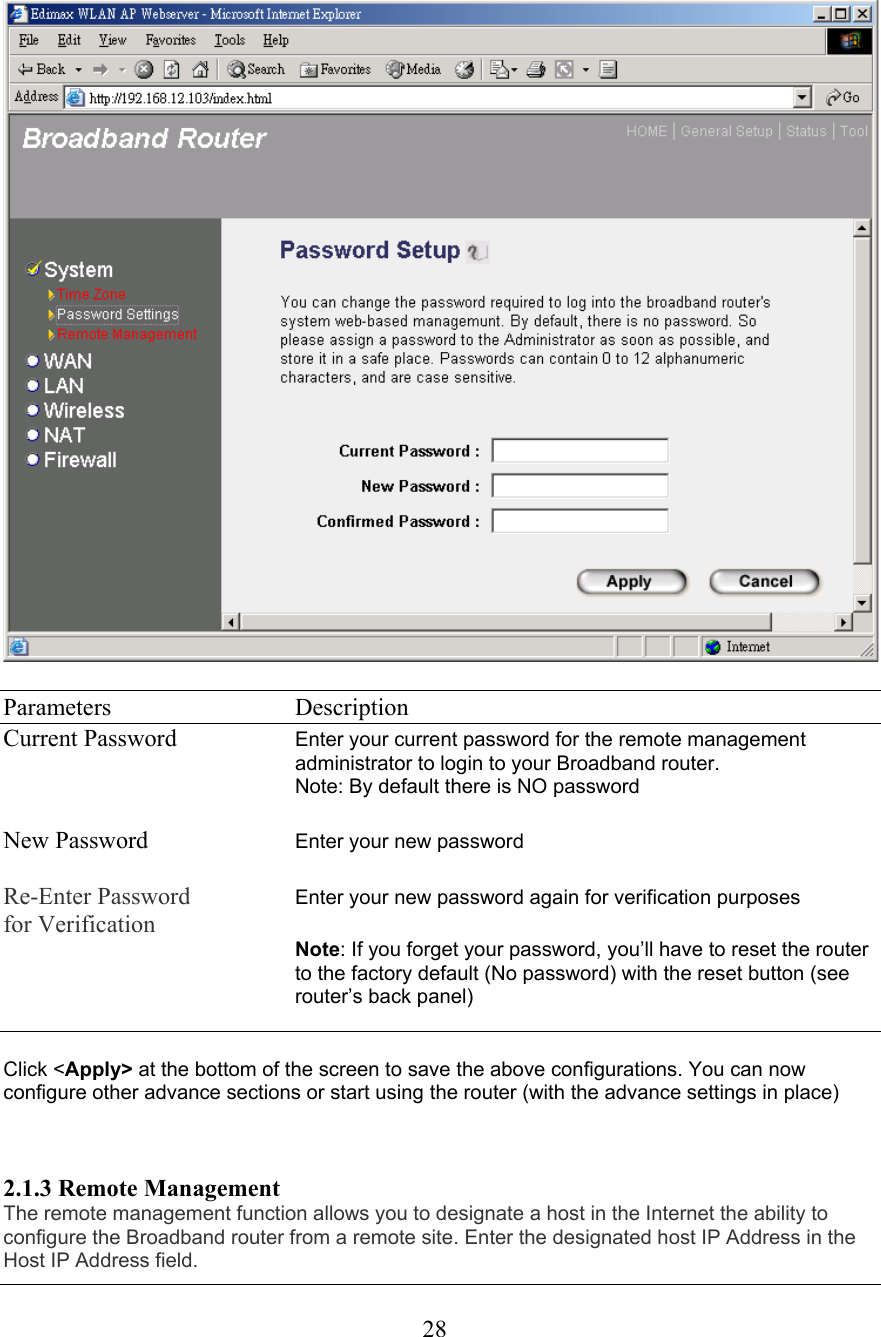
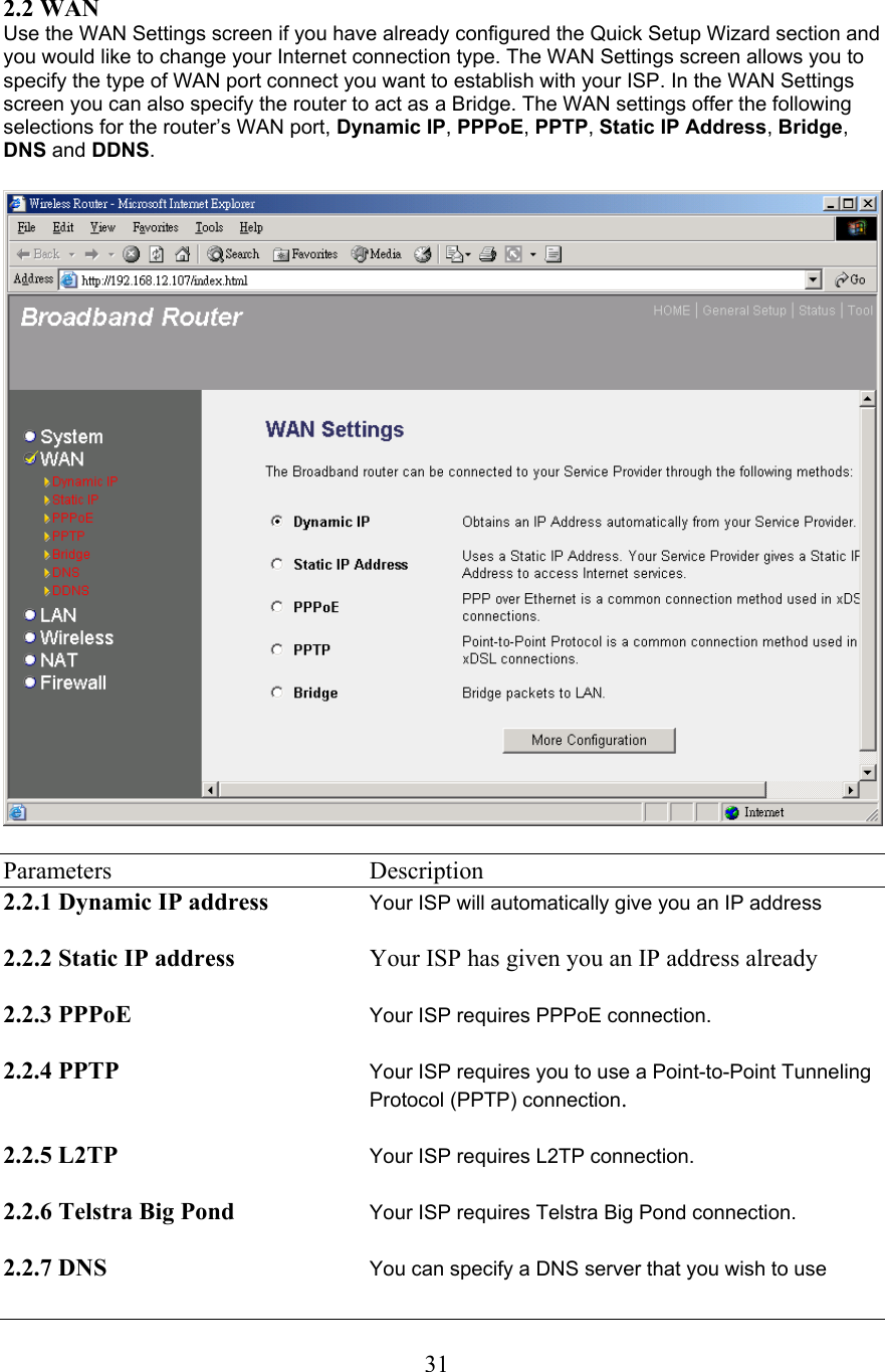
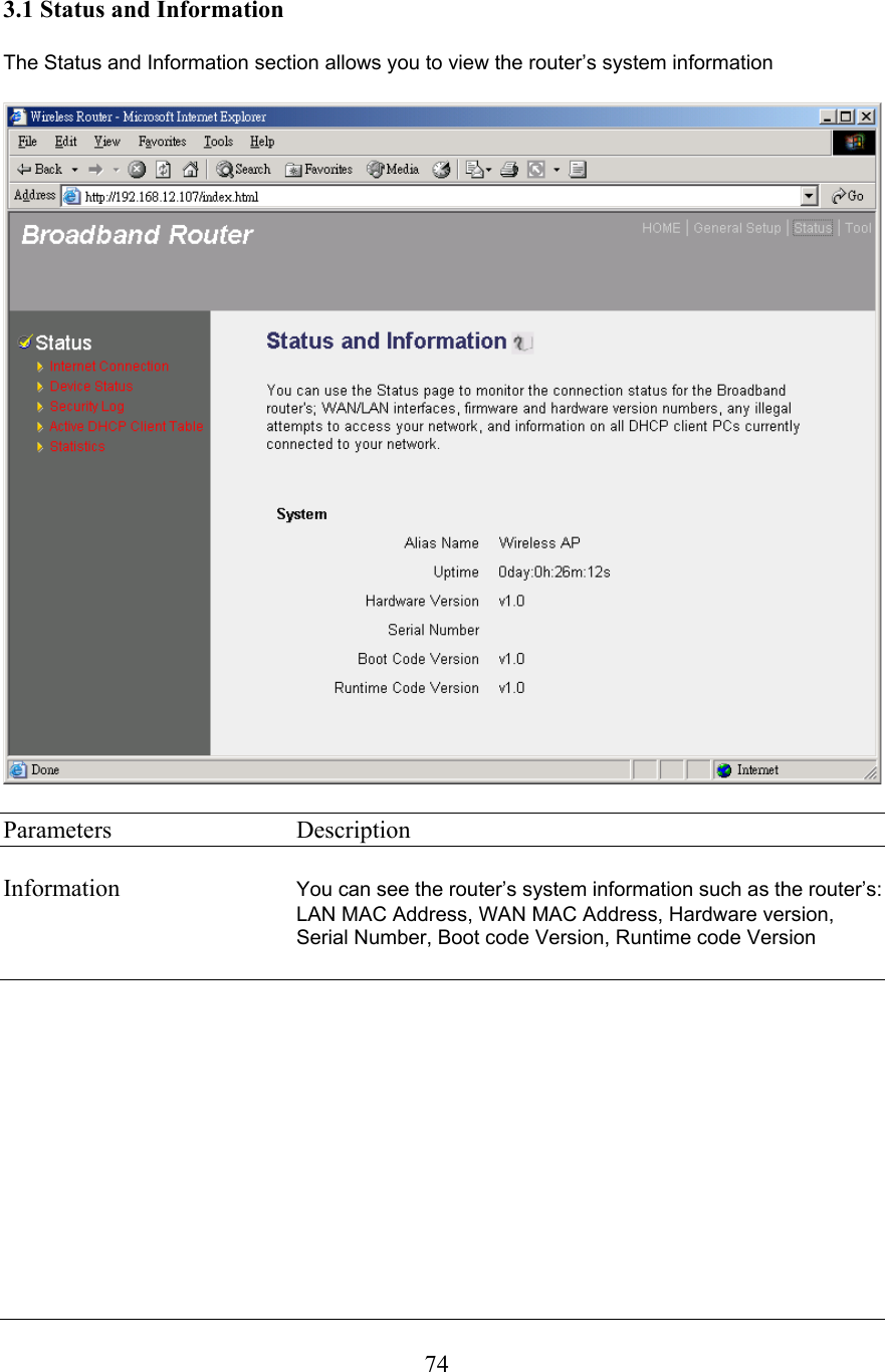
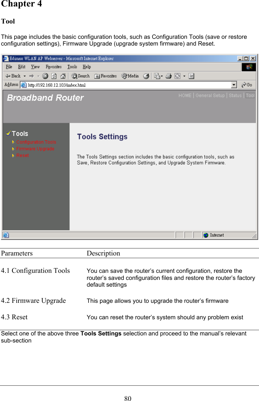
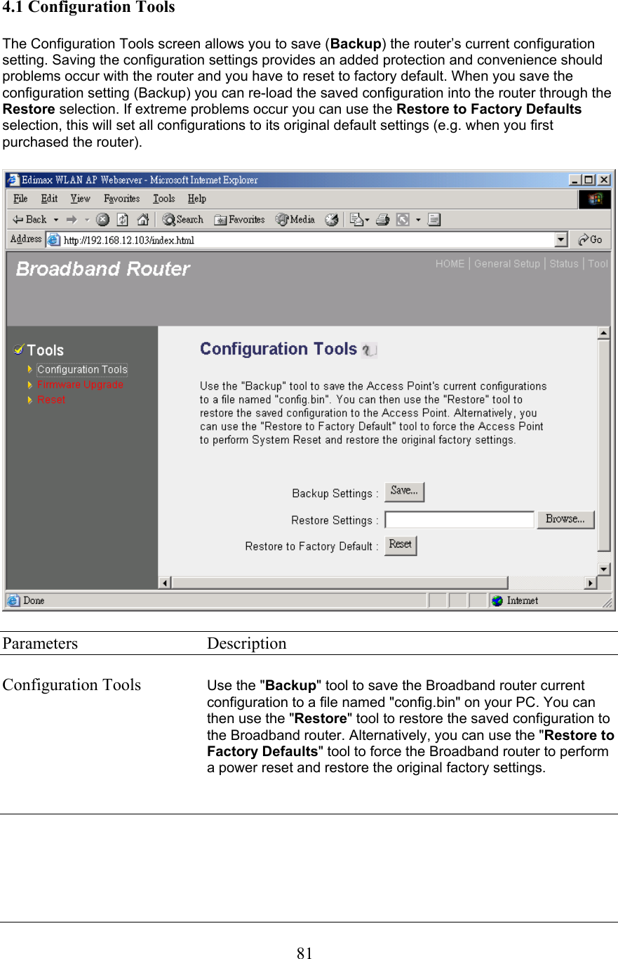
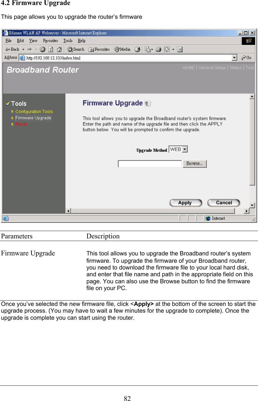
USERS MANUAL
Navigation menu
Upload a User Manual
Namespaces
Wiki Guide
HTML
PDF
Info
Views
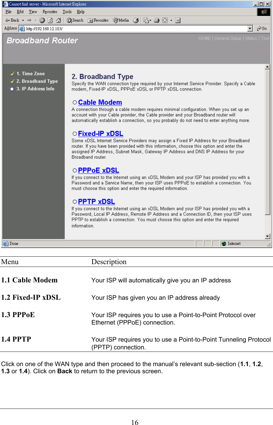
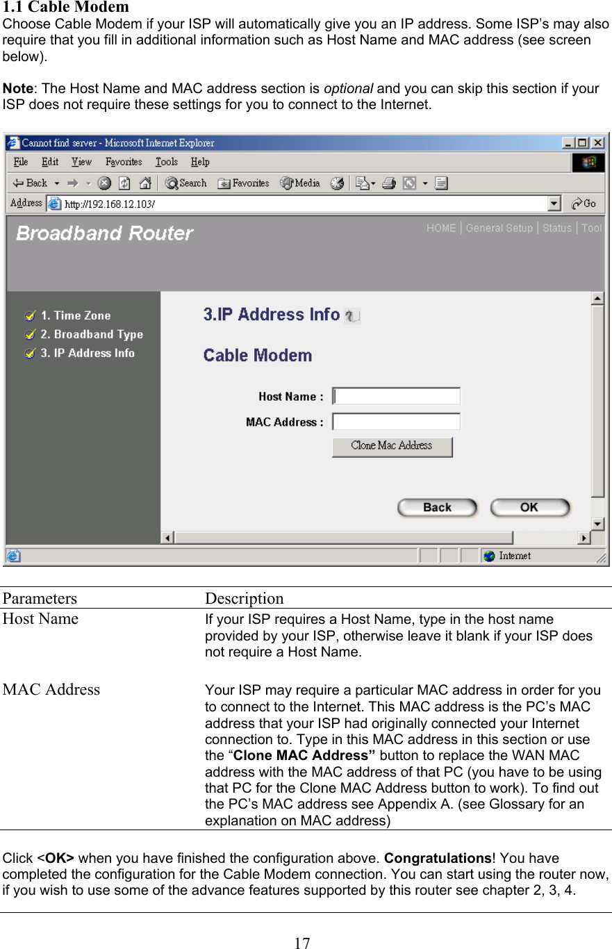
User Manual
Discussion / Help
Navigation

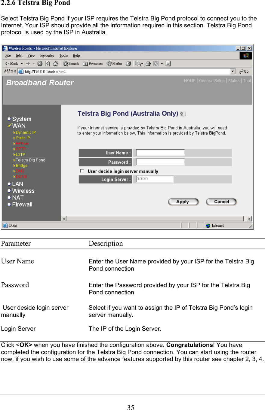
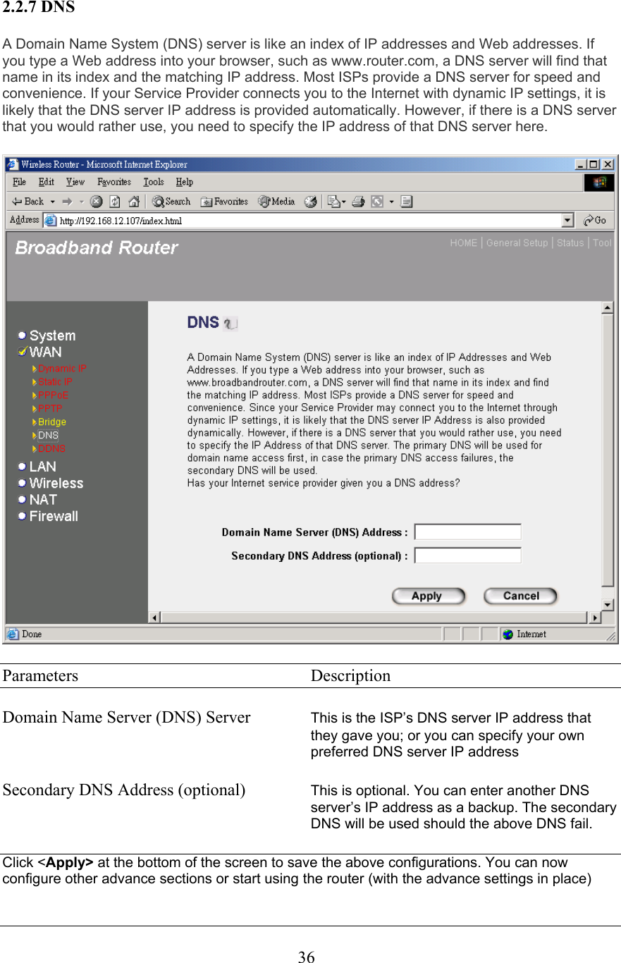
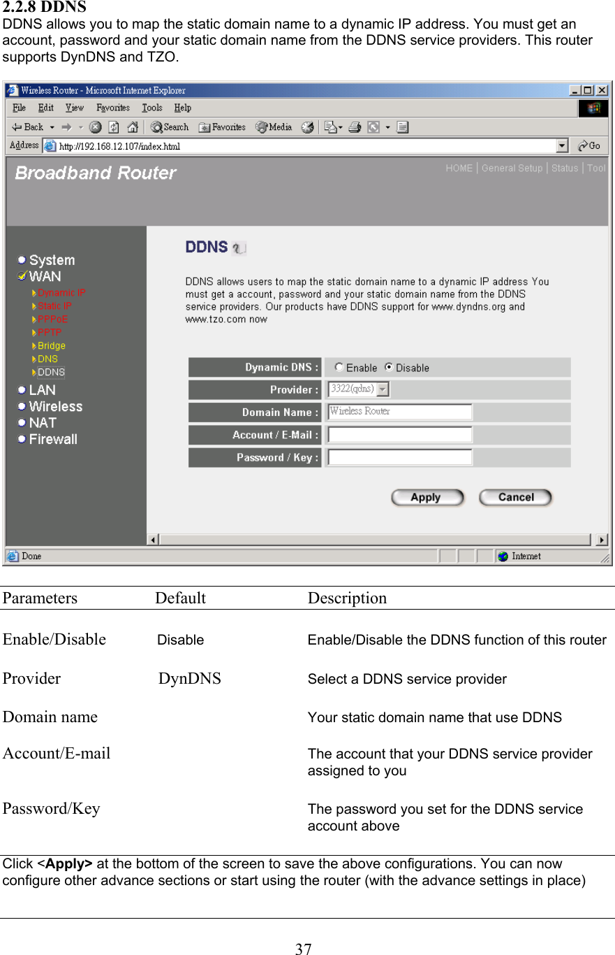
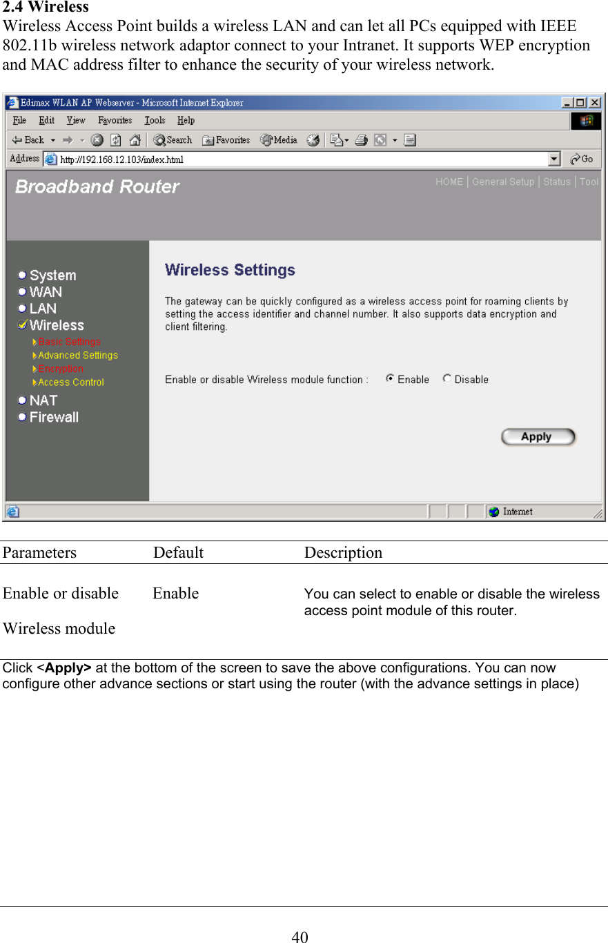
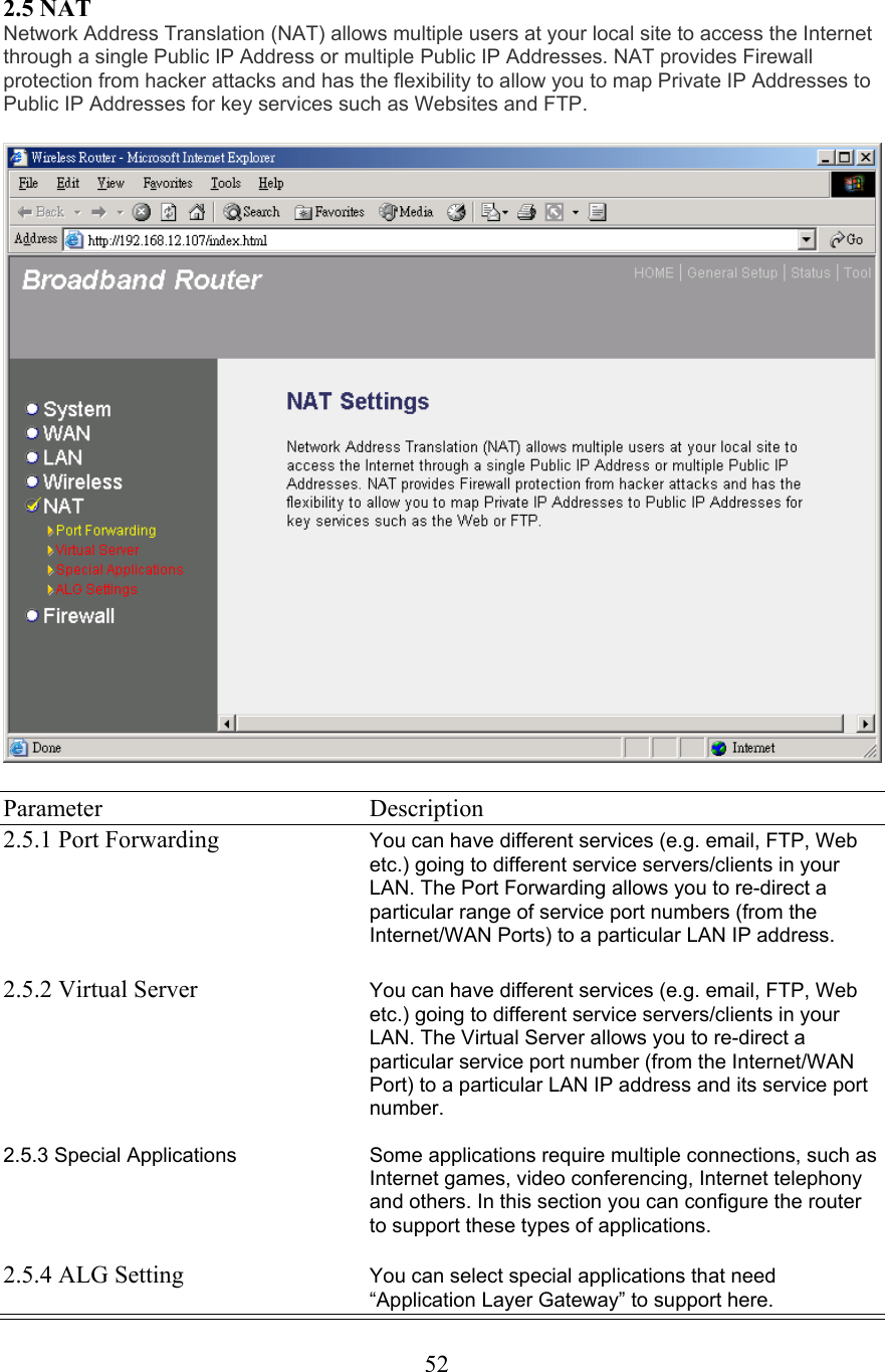
![8: Reboot the PC. Your PC will now obtain an IP address automatically from your Broadband Router’s DHCP server.Note: Please make sure that the Broadband router’s DHCP server is the only DHCP serveravailable on your LAN. Once you’ve configured your PC to obtain an IP address automatically, please proceed toStep 3 (Page 11).2b) Windows 2000 1: Click the Start button and select Settings, then click Control Panel. The Control Panel window will appear. 2: Double-click Network and Dial-up Connections icon. In the Network and Dial-up Connection window, double-click Local Area Connection icon. The Local Area Connection window will appear. 3: In the Local Area Connection window, click the Properties button. 4: Check your list of Network Components. You should see Internet Protocol [TCP/IP] on your list. Select it and click the Properties button. 5: In the Internet Protocol (TCP/IP) Properties window, select Obtain an IP address automatically and Obtain DNS server address automatically as shown on the followingscreen.8](https://usermanual.wiki/Edimax-Technology-Co/9561040401/User-Guide-394585-Page-9.png)