Edimax Technology Co 9562040507 Wireless Broadband Router User Manual Generic BR 6204Wg Manual02
Edimax Technology Co Ltd Wireless Broadband Router Generic BR 6204Wg Manual02
Contents
- 1. User Manual 1st 50 pages
- 2. User Manual fm p51
User Manual fm p51
51
2.4.3 Security
This Access Point provides complete wireless LAN security functions, include WEP,
IEEE 802.11x, IEEE 802.11x with WEP, WPA with pre-shared key and WPA with
RADIUS. With these security functions, you can prevent your wireless LAN from illegal
access. Please make sure your wireless stations use the same security function.
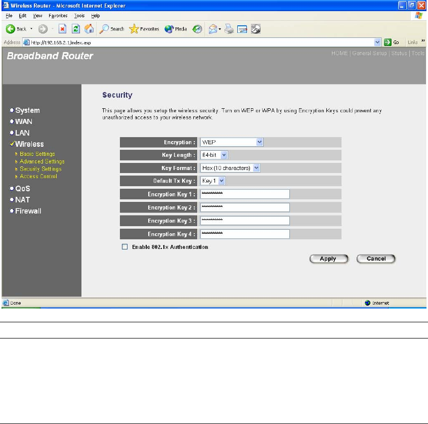
2.4.3.1 WEP only
When you select 64-bit or128-bit WEP key, you have to enter WEP keys to encrypt data.
You can generate the key by yourself and enter it. You can enter four WEP keys and
select one of them as default key. Then the router can receive any packets encrypted by
one of the four keys
Parameters Default Description
Key Length 64-bit You can select the WEP key length for
encryption, 64-bit or 128-bit. Larger WEP key
length will provide higher level of security, but
the throughput will be lower.

52
Key Format You may select to select ASCII Characters
(alphanumeric format) or Hexadecimal Digits (in
the "A-F", "a-f" and "0-9" range) to be the WEP
Key.
For example:
ASCII Characters: guest
Hexadecimal Digits: 12345abcde
Default Key Select one of the four keys to encrypt your data.
Only the key you select it in the "Default key" will
take effect.
Key 1 - Key 4 The WEP keys are used to encrypt data
transmitted in the wireless network. Fill the text
box by following the rules below.
64-bit WEP: input 10-digit Hex values (in the "A-
F", "a-f" and "0-9" range) or 5-digit ASCII
character as the encryption keys.
128-bit WEP: input 26-digit Hex values (in the
"A-F", "a-f" and "0-9" range) or 13-digit ASCII
characters as the encryption keys.
Click <Apply> at the bottom of the screen to save the above configurations. You can now
configure other advance sections or start using the router (with the advance settings in place)
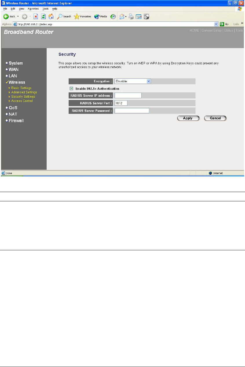
2.4.3.2 802.1x only
IEEE 802.1x is an authentication protocol. Every user must use a valid account to login
to this Access Point before accessing the wireless LAN. The authentication is processed
by a RADIUS server. This mode only authenticates user by IEEE 802.1x, but it does not
encryption the data during communication.
53
Parameters Default Description
RADIUS Server IP address The IP address of external RADIUS server.
RADIUS Server Port The service port of the external RADIUS server.
RADIUS Server Password The password used by external RADIUS server.
Click <Apply> at the bottom of the screen to save the above configurations. You can now
configure other advance sections or start using the router (with the advance settings in place)
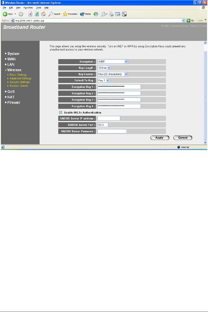
2.4.3.3 802.1x WEP Static key
IEEE 802.1x is an authentication protocol. Every user must use a valid account to login
to this Access Point before accessing the wireless LAN. The authentication is processed
by a RADIUS server. This mode also uses WEP to encrypt the data during
communication.
54
For the WEP settings, please refer to section 2.4.3.1 “WEP only”. For the 802.1x settings,
please refer to section 2.4.3.2 “802.1x only”.
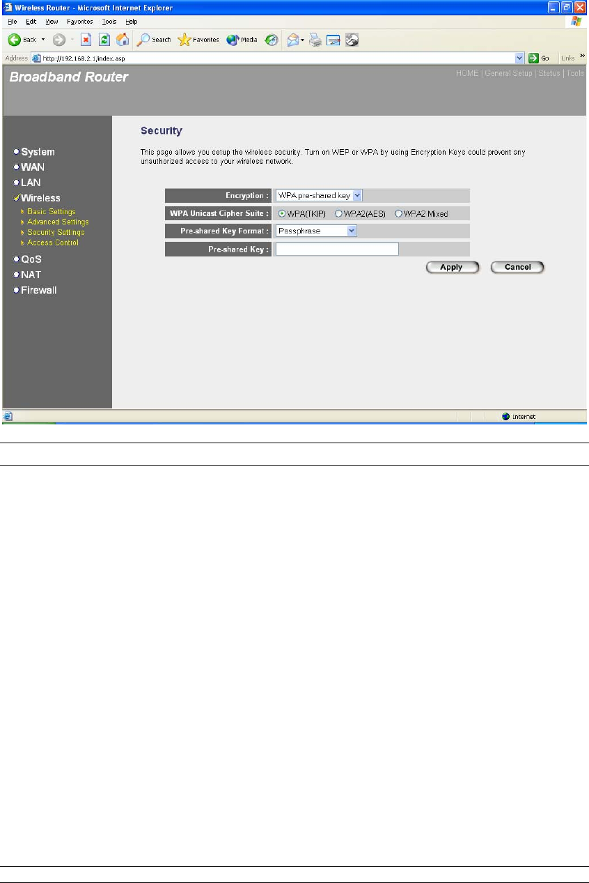
2.4.3.4 WPA Pre-shared key
Wi-Fi Protected Access (WPA) is an advanced security standard. You can use a pre-
shared key to authenticate wireless stations and encrypt data during communication. It
uses TKIP or CCMP(AES) to change the encryption key frequently. So the encryption
key is not easy to be broken by hackers. This can improve security very much.
55
Parameters Default Description
WPA(TKIP) TKIP can change the encryption key frequently
to enhance the wireless LAN security.
WPA2(AES) This use CCMP protocol to change encryption
key frequently. AES can provide high level
encryption to enhance the wireless LAN security.
WPA2 Mixed This will use TKIP or AES based on the other
communication peer automatically.
Pre-shared Key Format You may select to select Passphrase
(alphanumeric format) or Hexadecimal Digits (in
the “A-F”, “a-f” and “0-9” range) to be the Pre-
shared Key. For example:
Passphrase: iamguest
Hexadecimal Digits: 12345abcde
Pre-shared Key The Pre-shared key is used to authenticate and
encrypt data transmitted in the wireless network.
Fill the text box by following the rules below.
Hex WEP: input 64-digit Hex values (in the “A-F”,
“a-f” and “0-9” range) or at least 8 character pass
phrase as the pre-shared keys.
56
Click <Apply> at the bottom of the screen to save the above configurations. You can now
configure other advance sections or start using the router (with the advance settings in place)
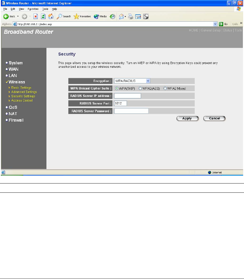
2.4.3.5 WPA Radius
Wi-Fi Protected Access (WPA) is an advanced security standard. You can use an external
RADIUS server to authenticate wireless stations and provide the session key to encrypt
data during communication. It uses TKIP or CCMP(AES) to change the encryption key
frequently. This can improve security very much.
Parameters Default Description
WPA(TKIP) TKIP can change the encryption key frequently
to enhance the wireless LAN security.
WPA2(AES) This use CCMP protocol to change encryption
key frequently. AES can provide high level
encryption to enhance the wireless LAN security.
WPA2 Mixed This will use TKIP or AES based on the other
communication peer automatically.
RADIUS Server IP address The IP address of external RADIUS server.

57
RADIUS Server Port The service port of the external RADIUS server.
RADIUS Server Password The password used by external RADIUS server.
Click <Apply> at the bottom of the screen to save the above configurations. You can now
configure other advance sections or start using the router (with the advance settings in place)
58
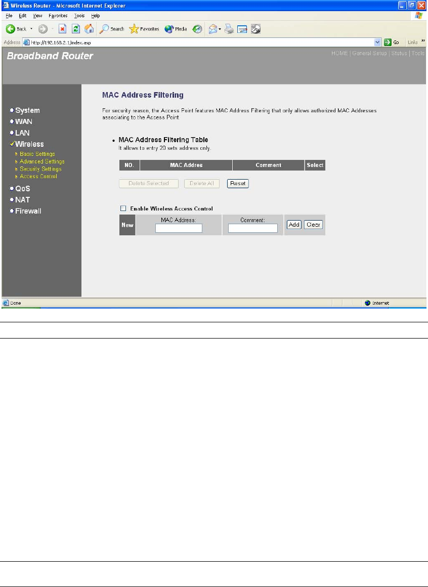
2.4.4 Access Control
This wireless router provides MAC Address Control, which prevents the unauthorized
MAC Addresses from accessing your wireless network.
Parameters Description
Enable wireless access control Enable wireless access control
Add MAC address into the list Fill in the "MAC Address" and "Comment" of the
wireless station to be added and then click "Add".
Then this wireless station will be added into the
"Current Access Control List" below. If you find
any issues before adding it and want to retype
again. Just click "Clear" and both "MAC
Address" and "Comment" fields will be cleared.
Remove MAC address from the list If you want to remove some MAC address from
the "Current Access Control List ", select the
MAC addresses you want to remove in the list
and then click "Delete Selected". If you want
remove all MAC addresses from the table, just
click "Delete All" button. Click "Reset" will clear
your current selections.

59
Click <Apply> at the bottom of the screen to save the above configurations. You can now
configure other advance sections or start using the router (with the advance settings in place)
60
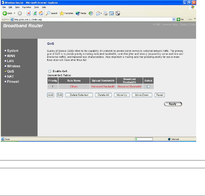
2.5 QoS
The QoS can let you classify Internet application traffic by source/destination IP address
and port number. You can assign priority for each type of application and reserve
bandwidth for it. The packets of applications with higher priority will always go first.
Lower priority applications will get bandwidth after higher priority applications get
enough bandwidth. This can let you have a better experience in using critical real time
services like Internet phone, video conference …etc. All the applications not specified by
you are classified as rule name “Others”. The rule with smaller priority number has
higher priority; the rule with larger priority number has lower priority. You can adjust the
priority of the rules by moving them up or down.
Note: If the total assigned bandwidth of higher priority applications is larger than
the maximum bandwidth provided by the WAN port, the other applications will not
get any bandwidth.
Parameters Description
Enable/Disable QoS You can check “Enable QoS” to enable QoS
function for the WAN port. You also can uncheck

61
“Enable QoS” to disable QoS function for the
WAN port.
Add a QoS rule into the table Click “Add” then you will enter a form of the QoS
rule. Click “Apply” after filling out the form and
the rule will be added into the table.
Remove QoS rules from the table If you want to remove some QoS rules from the
table, select the QoS rules you want to remove
in the table and then click "Delete Selected". If
you want remove all QoS rules from the table,
just click "Delete All" button. Click "Reset" will
clear your current selections.
Edit a QoS rule Select the rule you want to edit and click “Edit”,
then you will enter the detail form of the QoS
rule. Click “Apply” after editing the form and the
rule will be saved.
Adjust QoS rule priority You can select the rule and click “Move Up” to
make its priority higher. You also can select the
rule and click “Move Down” to make its priority
lower.
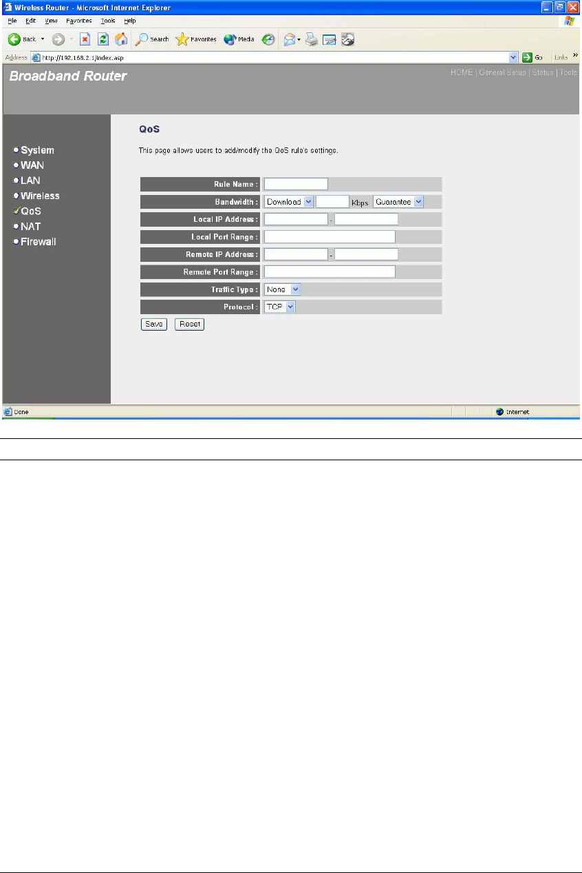
Edit QoS Rule:
You can assign packet classification criteria by its local IP range, remote IP range, traffic type,
protocol, local port range and remote port range parameters. The parameters that you leave as
blank will be ignored. The priority of this rule will be applied to packets that match classification
criteria of this rule. You can limit bandwidth consumed by packets that match this rule or
guarantee bandwidth required by packets that match this rule.
62
Parameters Description
Rule Name The name of this rule.
Bandwidth You can assign the download or upload
bandwidth by the unit of Kbps (1024 bit per
second). You can limit the maximum bandwidth
consumed by this rule by selecting “Maximum”.
You also can reserve enough bandwidth for this
rule by selecting “Guarantee”.
Local IP Address Enter the local IP address range of the packets
that this rule will apply to. If you assign
192.168.2.3 – 192.168.2.5, it means 3 IP
addresses: 192.168.2.3, 192.168.2.4 and
192.168.2.5
Local Port Range Enter the local port range of the packets that this
rule will apply to. You can assign a single port
number here or assign a range of port numbers
by assigning the first port number and the last
port number of the range. The two numbers are
separated by a dash “-“, for example “101-150”
means from port number 100 to port number
150 – the range of 50 port numbers.

63
Remote IP Address Enter the remote IP address range of the
packets that this rule will apply to. If you assign
192.168.2.3 – 192.168.2.5, it means 3 IP
addresses: 192.168.2.3, 192.168.2.4 and
192.168.2.5
Remote Port Range Enter the remote port range of the packets that
this rule will apply to. You can assign a single
port number here or assign a range of port
numbers by assigning the first port number and
the last port number of the range. The two
numbers are separated by a dash “-“, for
example “101-150” means from port number 100
to port number 150 – the range of 50 port
numbers.
Traffic Type Select the traffic type of the packets that this rule
will apply to. We list some popular applications
here to ease the configuration. You also can get
the same result by using other parameters, for
example source or destination port number, if
you are familiar with the application protocol.
Protocol Select the protocol type of the packets that this
rule will apply to.
Apply Apply and exit the form.
Reset Clear the content of this form.
Click <Apply> at the bottom of the screen to save the above configurations. You can now
configure other advance sections or start using the router (with the advance settings in place)
64
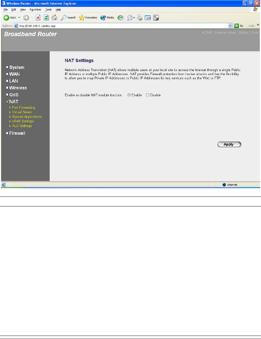
2.6 NAT
Network Address Translation (NAT) allows multiple users at your local site to access the Internet
through a single Public IP Address or multiple Public IP Addresses. NAT provides Firewall
protection from hacker attacks and has the flexibility to allow you to map Private IP Addresses to
Public IP Addresses for key services such as Websites and FTP.
Parameter Description
2.6.1 Port Forwarding You can have different services (e.g. email, FTP, Web
etc.) going to different service servers/clients in your
LAN. The Port Forwarding allows you to re-direct a
particular range of service port numbers (from the
Internet/WAN Ports) to a particular LAN IP address.
2.6.2 Virtual Server You can have different services (e.g. email, FTP, Web
etc.) going to different service servers/clients in your
LAN. The Virtual Server allows you to re-direct a
particular service port number (from the Internet/WAN
Port) to a particular LAN IP address and its service port
number.
2.6.3 Special Applications Some applications require multiple connections, such as
Internet games, video conferencing, Internet telephony
and others. In this section you can configure the router
to support these types of applications.

65
2.6.4 UPnP Setting It allows to Enable or Disable UPnP feature here. After
you enable the UPnP feature, all client systems that
support UPnP, like Windows XP, can discover this router
automatically and access the Internet through this router
without any configuration. The NAT Traversal function
provided by UPnP can let applications that support
UPnP smoothly connect to Internet sites without any
incompatibility problem due to the NAPT port translation.
2.6.5 ALG Setting You can select special applications that need
“Application Layer Gateway” to support here.
2.6.6 Static Routing You can disable NAT function and setup the routing
rules manually.
Click on one of the three NAT selections and proceed to the manual's relevant sub-
section.
66
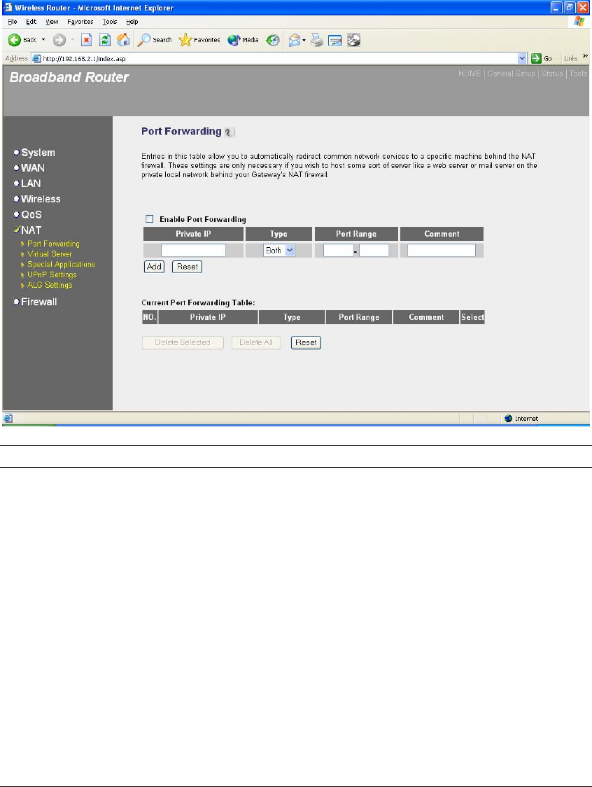
2.6.1 Port Forwarding
The Port Forwarding allows you to re-direct a particular range of service port numbers (from the
Internet/WAN Ports) to a particular LAN IP address. It help you to host some servers behind the
router NAT firewall.
Parameter Description
Enable Port Forwarding Enable Port Forwarding
Private IP This is the private IP of the server behind the
NAT firewall.
Note: You need to give your LAN PC clients a
fixed/static IP address for Port Forwarding to
work properly.
Type This is the protocol type to be forwarded. You
can choose to forward “TCP” or “UDP” packets
only or select “both” to forward both “TCP” and
“UDP” packets.
Port Range The range of ports to be forward to the private IP.
Comment The description of this setting.

67
Add Port Forwarding into the table Fill in the "Private IP", “Type”, “Port Range” and
"Comment" of the setting to be added and then
click "Add". Then this Port Forwarding setting
will be added into the "Current Port Forwarding
Table" below. If you find any typo before adding
it and want to retype again, just click "Clear" and
the fields will be cleared.
Remove Port Forwarding into the table If you want to remove some Port Forwarding
settings from the " Current Port Forwarding
Table", select the Port Forwarding settings you
want to remove in the table and then click
"Delete Selected". If you want remove all Port
Forwarding settings from the table, just click
"Delete All" button. Click "Reset" will clear your
current selections.
Click <Apply> at the bottom of the screen to save the above configurations. You can now
configure other advance sections or start using the router (with the advance settings in place)
68
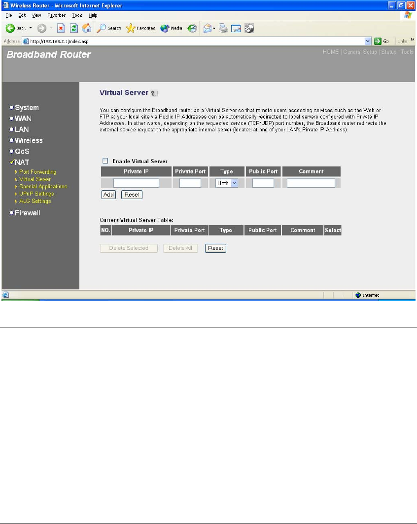
2.6.2 Virtual Server
Use the Virtual Server function when you want different servers/clients in your LAN to handle
different service/Internet application type (e.g. Email, FTP, Web server etc.) from the Internet.
Computers use numbers called port numbers to recognize a particular service/Internet application
type. The Virtual Server allows you to re-direct a particular service port number (from the
Internet/WAN Port) to a particular LAN private IP address and its service port number. (See
Glossary for an explanation on Port number)
Parameters Description
Enable Virtual Server Enable Virtual Server.
Private IP This is the LAN client/host IP address that the Public Port
number packet will be sent to.
Note: You need to give your LAN PC clients a fixed/static IP
address for Virtual Server to work properly.
Private Port This is the port number (of the above Private IP host) that the
below Public Port number will be changed to when the packet
enters your LAN (to the LAN Server/Client IP)
Type Select the port number protocol type (TCP, UDP or both). If you
are unsure, then leave it to the default both protocol.

69
Public Port Enter the service (service/Internet application) port number
from the Internet that will be re-directed to the above Private IP
address host in your LAN
Note: Virtual Server function will have priority over the DMZ
function if there is a conflict between the Virtual Server and the
DMZ settings.
Comment The description of this setting.
Add Virtual Server Fill in the "Private IP", "Private Port", "Type", “Public
Port” and "Comment" of the setting to be added and then
click "Add". Then this Virtual Server setting will be added
into the "Current Virtual Server Table" below. If you find
any typo before adding it and want to retype again, just
click "Clear" and the fields will be cleared.
Remove Virtual Server If you want to remove some Virtual Server settings from
the " Current Virtual Server Table", select the Virtual
Server settings you want to remove in the table and then
click "Delete Selected". If you want remove all Virtual
Server settings from the table, just click "Delete All" button.
Click "Reset" will clear your current selections.
Click <Apply> at the bottom of the screen to save the above configurations. You can now
configure other advance sections or start using the router (with the advance settings in place)
70
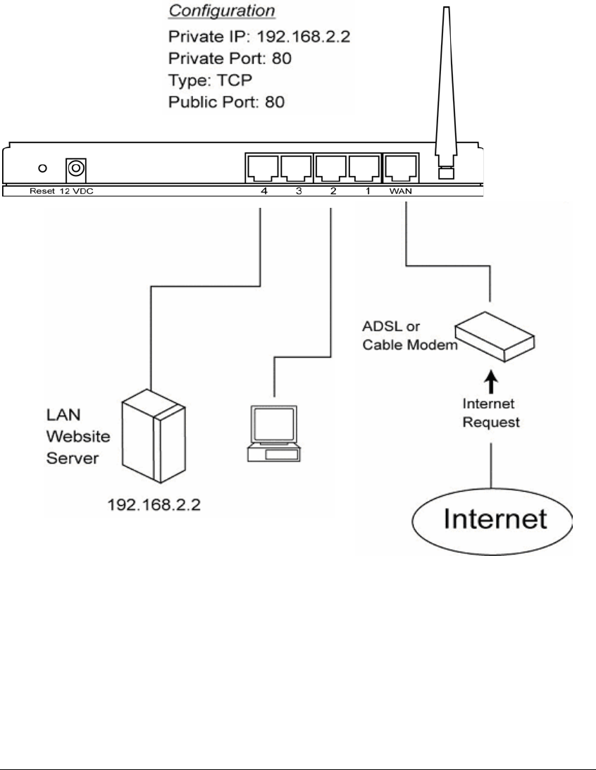
Example: Virtual Server
The diagram below demonstrates one of the ways you can use the Virtual Server function. Use
the Virtual Server when you want the web server located in your private LAN to be accessible to
Internet users. The configuration below means that any request coming form the Internet to
access your web server will be translated to your LAN’s web server (192.168.2.2). Note: For the
virtual server to work properly Internet/remote users must know your global IP address. (For
websites you will need to have a fixed/static global/public IP address)
71
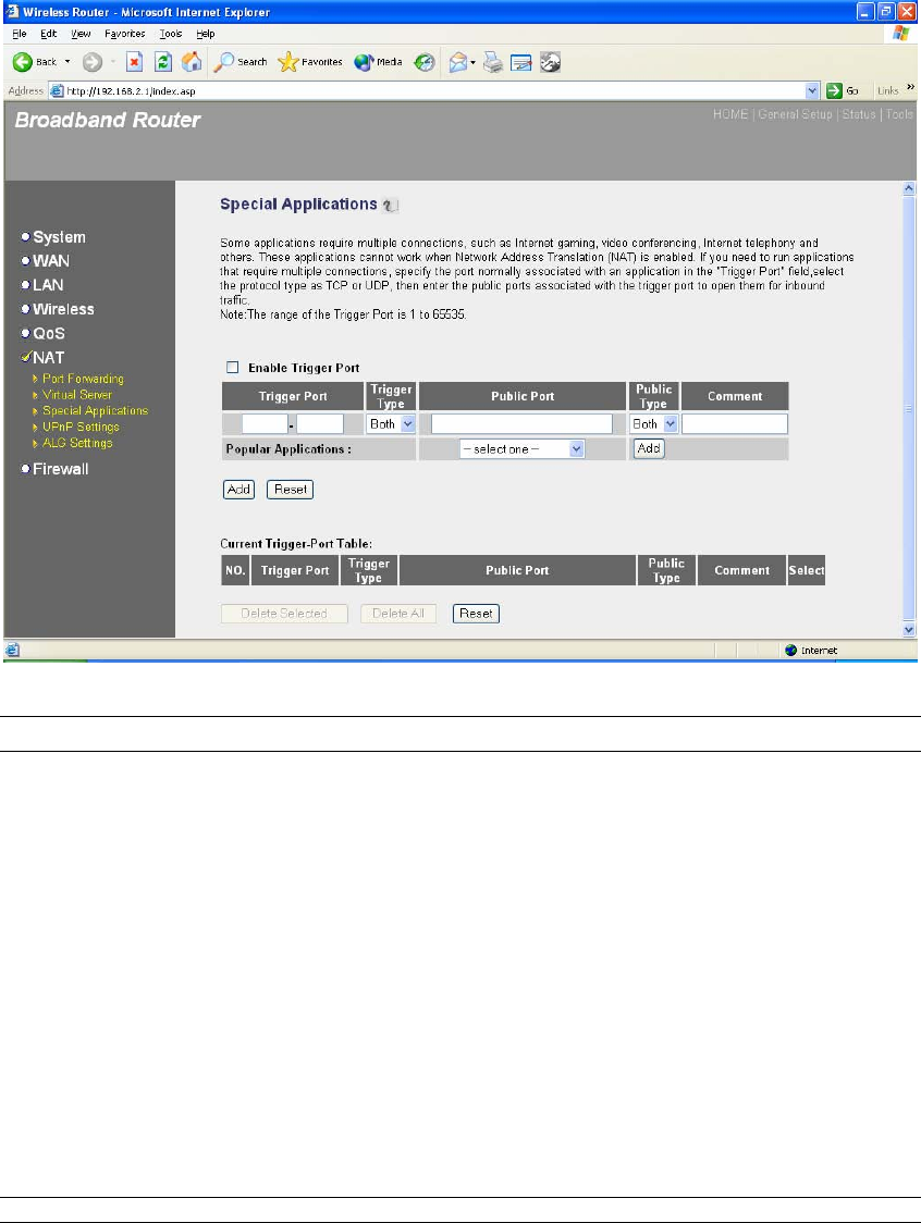
2.6.3 Special Applications
Some applications require multiple connections, such as Internet games, video conferencing,
Internet telephony and others. In this section you can configure the router to support multiple
connections for these types of applications.
Parameters Description
Enable Trigger Port Enable the Special Application function.
Trigger Port This is the out going (Outbound) range of port numbers for this
particular application
Trigger Type Select whether the outbound port protocol is “TCP”, “UDP” or
both.
Public Port Enter the In-coming (Inbound) port or port range for this type of
application (e.g. 2300-2400, 47624)
Note: Individual port numbers are separated by a comma
(e.g. 47624, 5775, 6541 etc.). To input a port range use a “dash”
to separate the two port number range (e.g. 2300-2400)
Public Type Select the Inbound port protocol type: “TCP”, “UDP” or both

72
Comment The description of this setting.
Popular applications This section lists the more popular applications that require
multiple connections. Select an application from the Popular
Applications selection. Once you have selected an application,
select a location (1-10) in the Copy to selection box and then
click the Copy to button. This will automatically list the Public
Ports required for this popular application in the location (1-10)
you’d specified.
Add Special Application Fill in the "Trigger Port", "Trigger Type”, “Public Port”,
"Public Type", "Public Port" and "Comment" of the setting
to be added and then click "Add". Then this Special
Application setting will be added into the "Current Trigger-
Port Table" below. If you find any typo before adding it
and want to retype again, just click "Clear" and the fields
will be cleared.
If you want to add a popular application, select one
“Popular Application” and then click “Add”.
Remove Special Application If you want to remove some Special Application settings
from the " Current Trigger-Port Table", select the Special
Application settings you want to remove in the table and
then click "Delete Selected". If you want remove all
Special Appliacation settings from the table, just click
"Delete All" button. Click "Reset" will clear your current
selections.
Click <Apply> at the bottom of the screen to save the above configurations. You can now
configure other advance sections or start using the router (with the advance settings in place)
Example: Special Applications
If you need to run applications that require multiple connections, then specify the port (outbound)
normally associated with that application in the "Trigger Port" field. Then select the protocol type
(TCP or UDP) and enter the public ports associated with the trigger port to open them up for
inbound traffic.
Example:
ID Trigger Port Trigger Type Public Port Public Type Comment
1 28800 UDP 2300-2400, 47624 TCP MSN Game Zone
2 6112 UDP 6112 UDP Battle.net
In the example above, when a user trigger’s port 28800 (outbound) for MSN Game Zone then the
router will allow incoming packets for ports 2300-2400 and 47624 to be directed to that user.
Note: Only one LAN client can use a particular special application at a time.
73
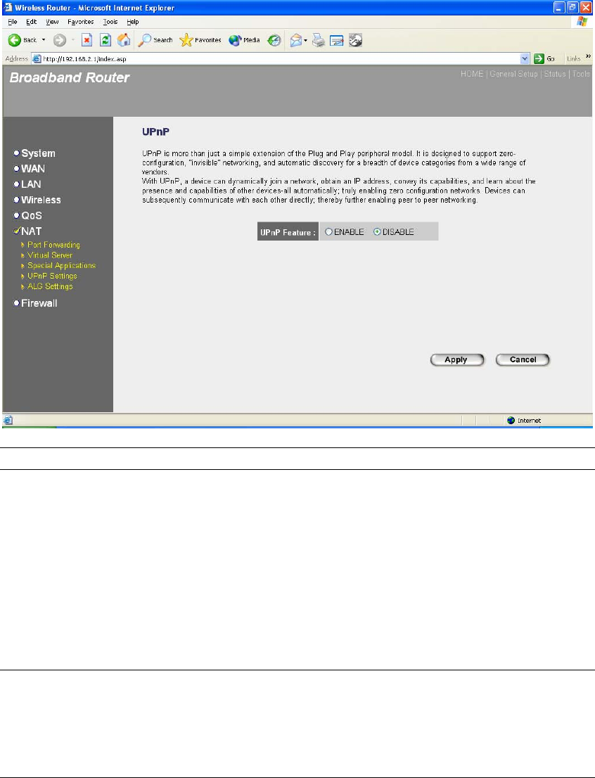
2.6.4 UPnP Settings
With UPnP, all PCs in you Intranet will discover this router automatically. So you do not
have to do any configuration for your PC and can access the Internet through this router
easily.
Parameters Default Description
UPnP Feature Disable You can Enable or Disable UPnP feature here.
After you enable the UPnP feature, all client
systems that support UPnP, like Windows XP,
can discover this router automatically and
access the Internet through this router without
any configuration. The NAT Traversal function
provided by UPnP can let applications that
support UPnP smoothly connect to Internet sites
without any incompatibility problem due to the
NAPT port translation.
Click <Apply> at the bottom of the screen to save the above configurations. You can now
configure other advance sections or start using the router (with the advance settings in place)
74
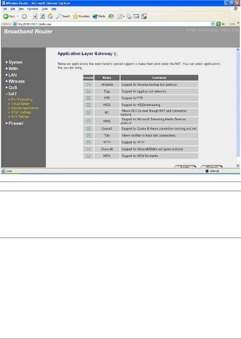
2.6.5 ALG Settings
You can select applications that need “Application Layer Gateway” to support.
Parameters Default Description
Enable You can select to enable “Application Layer
Gateway”, then the router will let that
application correctly pass though the NAT
gateway.
Click <Apply> at the bottom of the screen to save the above configurations. You can now
configure other advance sections or start using the router (with the advance settings in place)
75
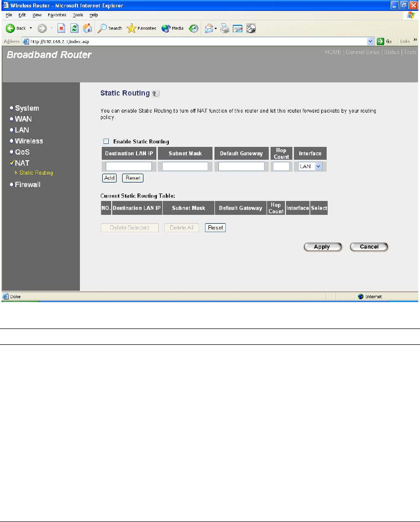
2.6.6 Static Routing
This router provides Static Routing function when NAT is disabled. With Static Routing,
the router can forward packets according to your routing rules. The IP sharing function
will not work any more in Static Routing mode.
Note: The DMZ function of firewall will not work if static routing is enabled.
Parameter Description
Enable Static Routing Static Routing function is default disabled. You
have to enable the Static Routing function before
your routing rules take effect.
Destination LAN IP The network address of destination LAN.
Subnet Mask The subnet mask of destination LAN.
Default Gateway The next stop gateway of the path toward the
destination LAN. This is the IP of the neighbor

76
router that this router should communicate with on
the path to the destination LAN.
Hop Count The number of hops (routers) to pass through to
reach the destination LAN.
Interface The interface that go to the next hop (router).
Add a Rule Fill in the "Destination LAN IP", "Subnet Mask”,
“Default Gateway”, "Hop Count" and "Interface" of
the rule to be added and then click "Add". Then this
rule of Static Routing will be added into the "Static
Routing Table" below. If you find any typo before
adding it and want to retype again, just click
"Reset" and the fields will be cleared.
Remove a Rule If you want to remove some routing rules from the
"Static Routing Table", select the rules you want to
remove in the table and then click "Delete Selected".
If you want remove all rules from the table, just
click "Delete All" button. Click "Reset" will clear
your current selections.
Click <Apply> at the bottom of the screen to save the above configurations. You can now
configure other advance sections or start using the router (with the advance settings in place)
77
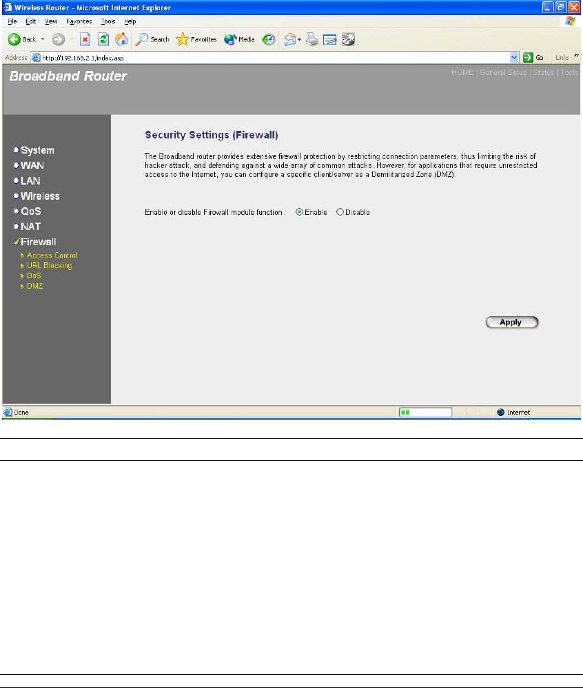
2.7 Firewall
The Broadband router provides extensive firewall protection by restricting connection parameters,
thus limiting the risk of hacker attack, and defending against a wide array of common Internet
attacks. However, for applications that require unrestricted access to the Internet, you can
configure a specific client/server as a Demilitarized Zone (DMZ).
Note: To enable the Firewall settings select Enable and click Apply
Parameters Description
2.6.1 Access Control Access Control allows you to specify which hosts users can or
cannot have access to certain Internet applications
2.6.2 URL Blocking URL Blocking allow you to specify which URLs can not be
accessed by users.
2.6.3 DoS The Broadband router's firewall can block common hacker
attacks and can log the attack activities.
2.6.4 DMZ The DMZ function allows you to re-direct all packets going to
your WAN port IP address to a particular IP address in your LAN.
78
Click on one of the firewall selections and proceed to the manual’s relevant sub-section
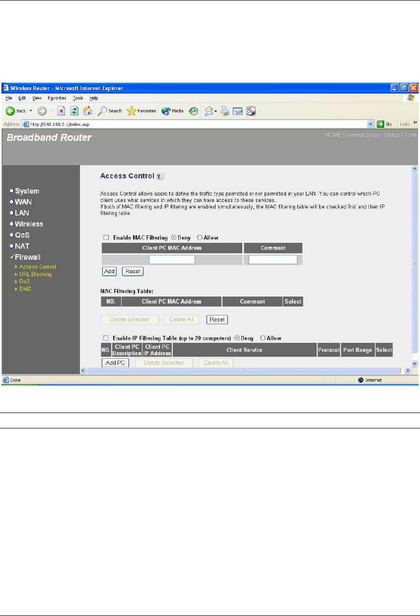
2.7.1 Access Control
If you want to restrict users from accessing certain Internet applications/services (e.g. Internet
websites, email, FTP etc.), then this is the place to set that configuration. Access Control allows
users to define the traffic type permitted in your LAN. You can control which PC client can have
access to these services.
Parameters Description
Deny If select “Deny” then all PCs will be allowed to
access Internet accept for the PCs in the list below.
Allow If select “Allow” then all PCs will be denied to
access Internet accept for the PCs in the list below.
Filter client PCs by IP Fill “IP Filtering Table” to filter PC clients by IP.
Add PC You can click Add PC to add an access control rule
for users by IP addresses.

79
Remove PC If you want to remove some PC from the "IP
Filtering Table", select the PC you want to remove
in the table and then click "Delete Selected". If you
want remove all PCs from the table, just click
"Delete All" button.
Filter client PC by MAC address Check “Enable MAC Filtering” to enable MAC
Filtering.
Add PC Fill in “Client PC MAC Address” and “Comment”
of the PC that is allowed to access the Internet, and
then click “Add”. If you find any typo before
adding it and want to retype again, just click
"Reset" and the fields will be cleared.
Remove PC If you want to remove some PC from the "MAC
Filtering Table", select the PC you want to remove
in the table and then click "Delete Selected". If you
want remove all PCs from the table, just click
"Delete All" button. If you want to clear the
selection and re-select again, just click “Reset”.
You can now configure other advance sections or start using the router (with the advance settings
in place)
80
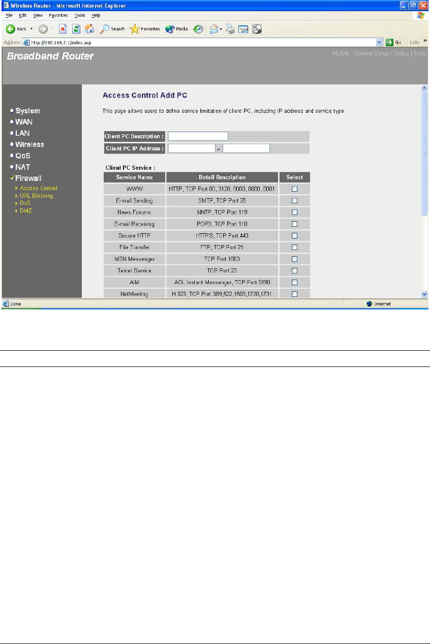
Add PC
Parameters Description
Client PC Description The description for this client PC rule.
Client PC IP Addresses Enter the IP address range that you wish to apply this
Access Control rule. This is the user’s IP address(es)
that you wish to setup an Access Control rule.
Note: You need to give your LAN PC clients a
fixed/static IP address for the Access Control rule to
work properly.
Client PC Service You can block the clients from accessing some
Internet services by checking the services you want
to block.
Protocol This allows you to select UDP, TCP or both
protocol type you want to block.
Port Range It can be assign up to five port ranges. The router
will block clients from accessing Internet services
that use these ports.
81
Apply Changes Click “Apply Changes” to save the setting.
Reset Click “Reset” to clear all fields.
Click <Apply Changes> at the bottom of the screen to save the above configurations. You can
now configure other advance sections or start using the router (with the advance settings in place)
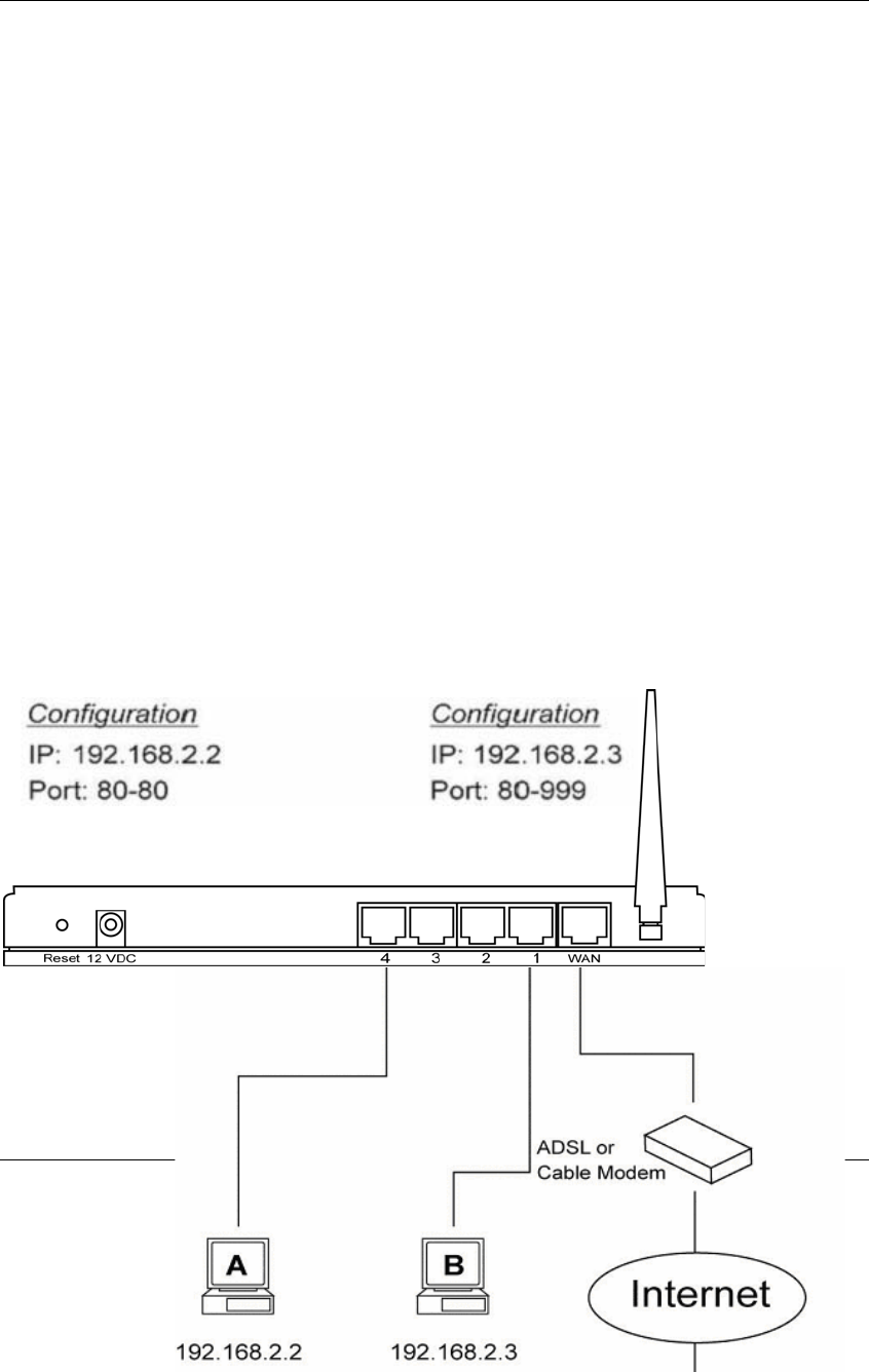
Example: Access Control
In the example below, LAN client A can only access websites that use Port 80. However, LAN
client B is able to access websites and any other service that uses ports between 80 and 999.

82
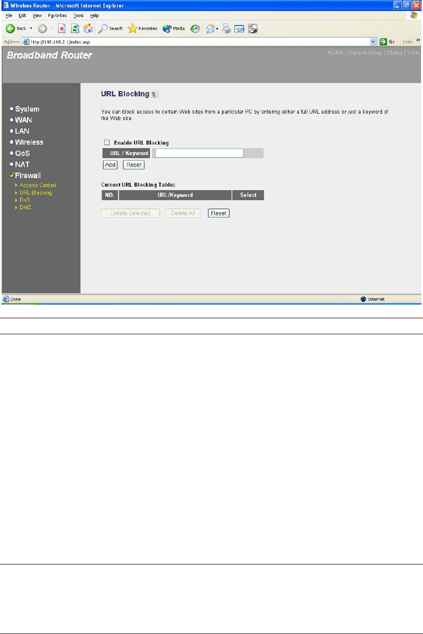
2.7.2 URL Blocking
You can block access to some Web sites from particular PCs by entering a full URL
address or just keyword of the Web site.
83
Parameters Description
Enable URL Blocking Enable/disable URL Blocking
Add URL Keyword Fill in “URL/Keyword” and then click “Add”. You
can enter the full URL address or the keyword of
the web site you want to block. If you find any typo
before adding it and want to retype again, just click
"Reset" and the field will be cleared.
Remove URL Keyword If you want to remove some URL keyword from the
"Current URL Blocking Table", select the URL
keyword you want to remove in the table and then
click "Delete Selected". If you want remove all
URL keyword from the table, just click "Delete All"
button. If you want to clear the selection and re-
select again, just click “Reset”.
You can now configure other advance sections or start using the router (with the advance settings
in place)

84
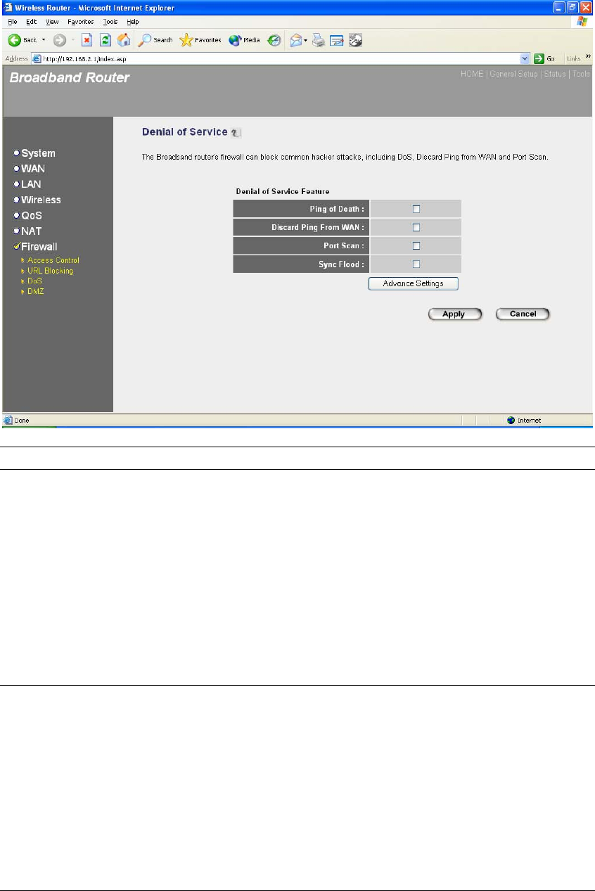
2.7.3 DoS (Denial of Service)
The Broadband router's firewall can block common hacker attacks, including Denial of Service,
Ping of Death, Port Scan and Sync Flood. If Internet attacks occur the router can log the events.
85
Parameters Description
Intrusion Detection Feature
Ping of Death Protections from Ping of Death attack
Discard Ping From WAN The router’s WAN port will not respond to any
Ping requests
Port Scan Protection the router from Port Scan.
Sync Flood Protection the router from Sync Flood attack.
Click <Apply> at the bottom of the screen to save the above configurations. You can now
configure other advance sections or start using the router (with the advance settings in place)
2.7.4 DMZ
If you have a local client PC that cannot run an Internet application (e.g. Games) properly from
behind the NAT firewall, then you can open the client up to unrestricted two-way Internet access
by defining a DMZ Host. The DMZ function allows you to re-direct all packets going to your WAN
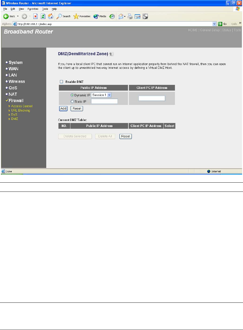
86
port IP address to a particular IP address in your LAN. The difference between the virtual server
and the DMZ function is that the virtual server re-directs a particular service/Internet application
(e.g. FTP, websites) to a particular LAN client/server, whereas DMZ re-directs all packets
(regardless of services) going to your WAN IP address to a particular LAN client/server.
Parameters Description
Enable DMZ Enable/disable DMZ
Note: If there is a conflict between the Virtual Server and the
DMZ setting, then Virtual Server function will have priority over
the DMZ function.
Public IP Address The IP address of the WAN port or any other Public IP
addresses given to you by your ISP
Client PC IP Address Input the IP address of a particular host in your LAN that will
receive all the packets originally going to the WAN port/Public IP
address above
Note: You need to give your LAN PC clients a fixed/static IP
address for DMZ to work properly.
You can now configure other advance sections or start using the router (with the advance settings
in place

87
Chapter 3
88
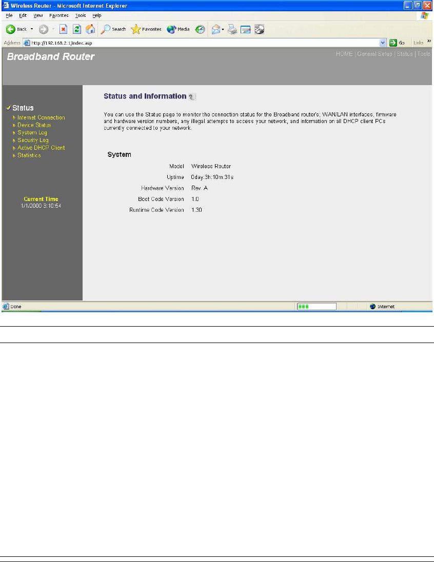
Status
The Status section allows you to monitor the current status of your router. You can use the Status
page to monitor: the connection status of the Broadband router's WAN/LAN interfaces, the
current firmware and hardware version numbers, any illegal attempts to access your network, and
information on all DHCP client PCs currently connected to your network.
Parameters Description
3.1 Status and Information Shows the router’s system information
3.2 Internet Connection View the Broadband router’s current Internet connection status
and other related information
3.3 Device Status View the Broadband router’s current setting status
3.4 System Log View the Broadband router’s system log
3.5 Security Log View any attempts that have been made to illegally gain access
to your network.
3.6 Active DHCP Client View your LAN client's information that is currently linked to the
Broadband router's DHCP server
89
3.7 Statistics Shows the statistics
Select one of the above five Status selections and proceed to the manual’s relevant sub-section
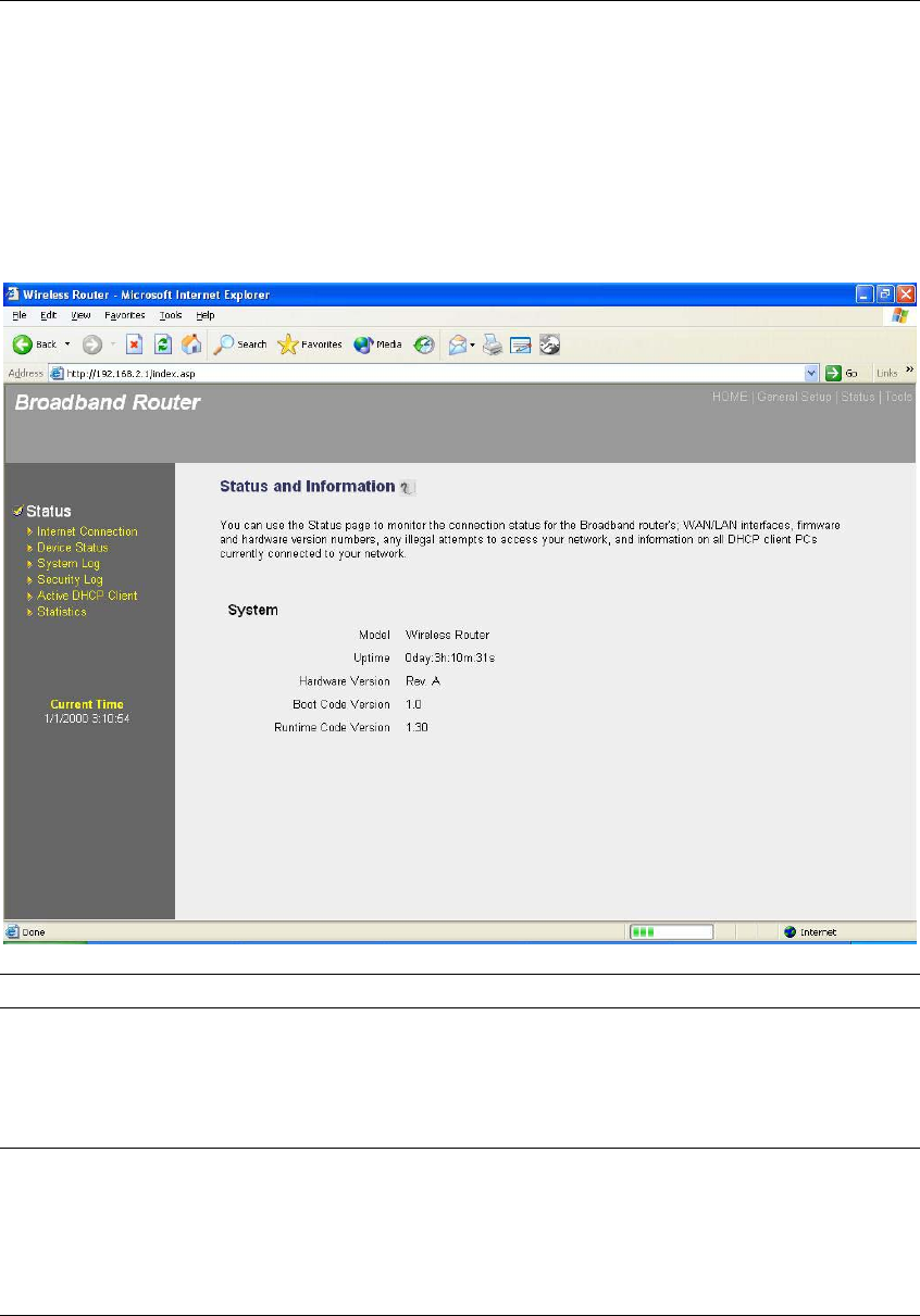
3.1 Status and Information
The Status and Information section allows you to view the router’s system information
Parameters Description
Information You can see the router’s system information such as the router’s:
LAN MAC Address, WAN MAC Address, Hardware version,
Serial Number, Boot code Version, Runtime code Version
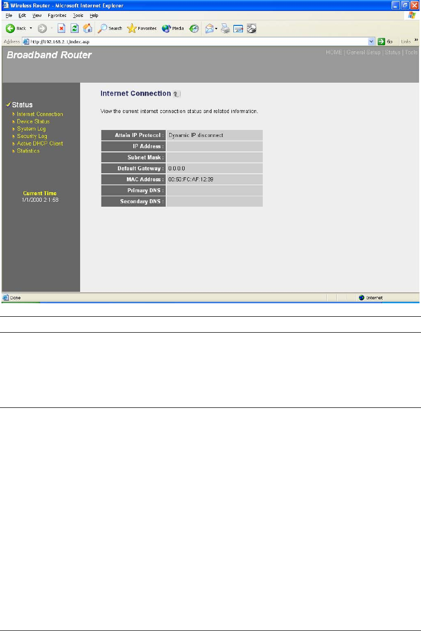
3.2 Internet Connection
View the Broadband router’s current Internet connection status and other related information
90
Parameters Description
Internet Connection This page displays whether the WAN port is connected to a
Cable/DSL connection. It also displays the router’s WAN port:
WAN IP address, Subnet Mask, and ISP Gateway as well as
the Primary DNS and Secondary DNS being used.
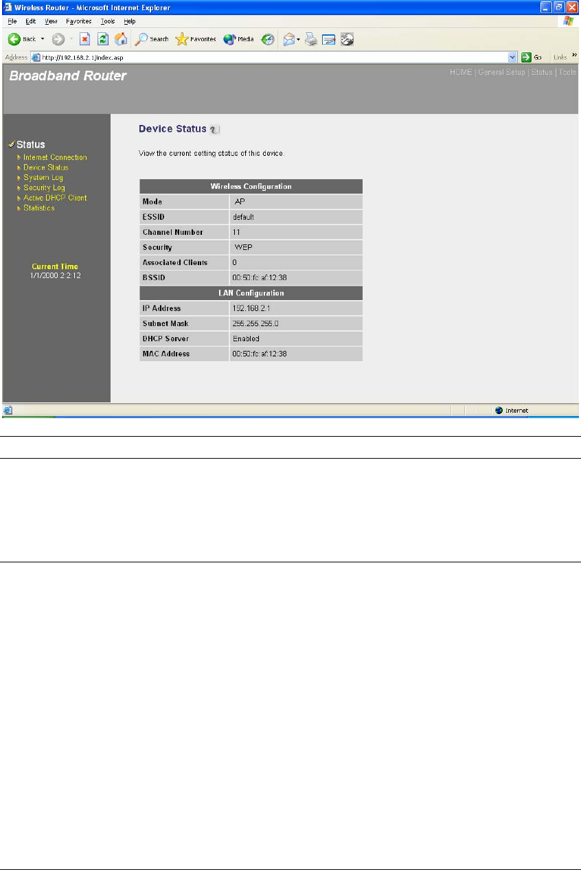
3.3 Device Status
View the Broadband router’s current configuration settings. The Device Status displays the
configuration settings you’ve configured in the Quick Setup Wizard/General Setup section.
91
Parameters Description
Device Status This page shows the Broadband router’s current device settings.
This page displays the Broadband router LAN port’s current LAN
IP Address and Subnet Mask. It also shows whether the DHCP
Server function is enabled/disabled..
92
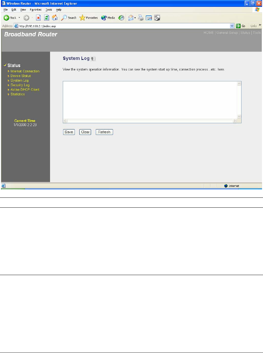
3.4 System Log
View the operation log of the system.
Parameters Description
System Log This page shows the current system log of the Broadband router.
It displays any event occurred after system start up.
At the bottom of the page, the system log can be saved <Save>
to a local file for further processing or the system log can be
cleared <Clear> or it can be refreshed <Refresh> to get the
most updated situation. When the system is powered down, the
system log will disappear if not saved to a local file.
93
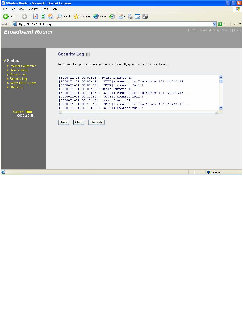
3.5 Security Log
View any attempts that have been made to illegally gain access to your network.
Parameters Description
Security Log This page shows the current security log of the Broadband router.
It displays any illegal attempts to access your network.
At the bottom of the page, the security log can be saved <Save>
to a local file for further processing or the security log can be
cleared <Clear> or it can be refreshed <Refresh> to get the
most updated situation. When the system is powered down, the
security log will disappear if not saved to a local file.
94
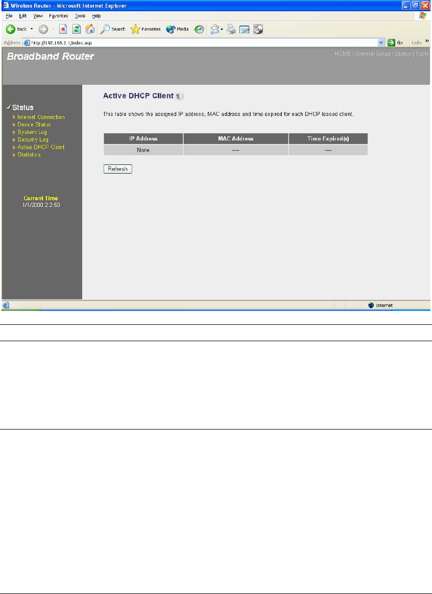
3.6 Active DHCP Client
View your LAN client's information that is currently linked to the Broadband router's DHCP server
Parameters Description
Active DHCP Client This page shows all DHCP clients (LAN PCs) currently
connected to your network. The “Active DHCP Client Table”
displays the IP address and the MAC address and Time Expired
of each LAN Client. Use the Refresh button to get the most
updated situation
95
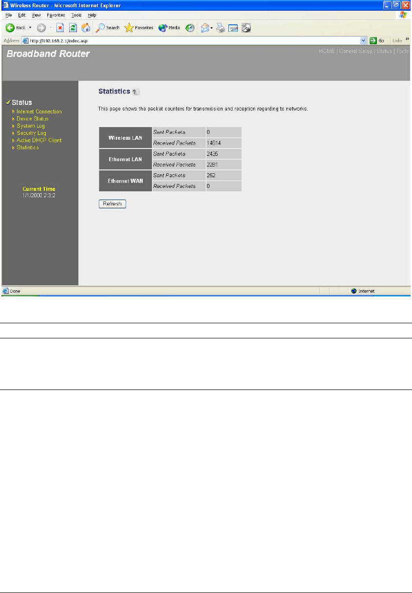
3.7 Statistics
View the statistics of packets sent and received on WAN, LAN and Wireless LAN.
Parameters Description
Statistics Shows the counters of packets sent and received on WAN,
LAN and Wireless LAN.
96
Chapter 4
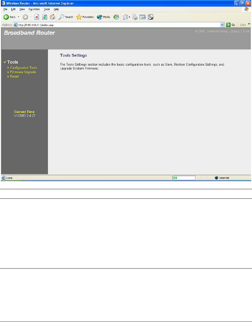
Tool
This page includes the basic configuration tools, such as Configuration Tools (save or restore
configuration settings), Firmware Upgrade (upgrade system firmware) and Reset.
Parameters Description
4.1 Configuration Tools You can save the router’s current configuration, restore the
router’s saved configuration files and restore the router’s factory
default settings
4.2 Firmware Upgrade This page allows you to upgrade the router’s firmware
4.3 Reset You can reset the router’s system should any problem exist
Select one of the above three Tools Settings selection and proceed to the manual’s relevant
sub-section
97
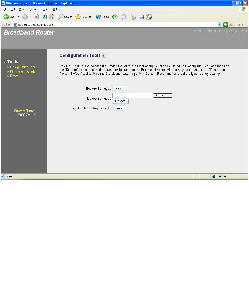
4.1 Configuration Tools
The Configuration Tools screen allows you to save (Backup) the router’s current configuration
setting. Saving the configuration settings provides an added protection and convenience should
problems occur with the router and you have to reset to factory default. When you save the
configuration setting (Backup) you can re-load the saved configuration into the router through the
Restore selection. If extreme problems occur you can use the Restore to Factory Defaults
selection, this will set all configurations to its original default settings (e.g. when you first
purchased the router).
Parameters Description
Configuration Tools Use the "Backup" tool to save the Broadband router current
configuration to a file named "config.bin" on your PC. You can
then use the "Restore" tool to restore the saved configuration to
the Broadband router. Alternatively, you can use the "Restore to
Factory Defaults" tool to force the Broadband router to perform
a power reset and restore the original factory settings.
98
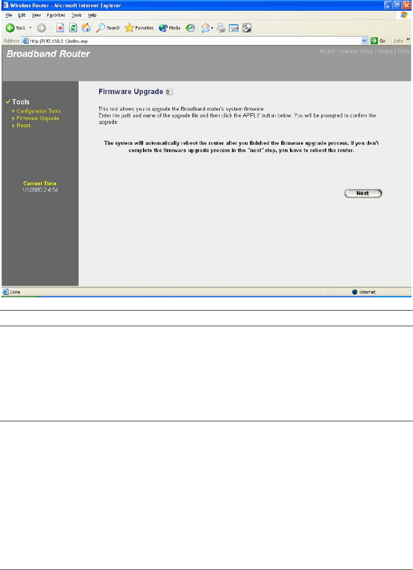
4.2 Firmware Upgrade
This page allows you to upgrade the router’s firmware
Parameters Description
Firmware Upgrade This tool allows you to upgrade the Broadband router’s system
firmware. To upgrade the firmware of your Broadband router,
you need to download the firmware file to your local hard disk,
and enter that file name and path in the appropriate field on this
page. You can also use the Browse button to find the firmware
file on your PC.
Once you’ve selected the new firmware file, click <Apply> at the bottom of the screen to start the
upgrade process. (You may have to wait a few minutes for the upgrade to complete). Once the
upgrade is complete you can start using the router.
99
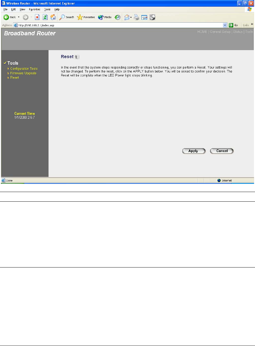
4.3 Reset
You can reset the router’s system should any problem exist. The reset function essentially
Re-boots your router’s system
Parameters Description
Reset In the event that the system stops responding correctly or in
some way stops functioning, you can perform a reset. Your
settings will not be changed. To perform the reset, click on the
<APPLY> button. You will be asked to confirm your decision.
The reset will be complete when the power light stops blinking.
Once the reset process is complete you may start using the
router again.
100
Appendix A
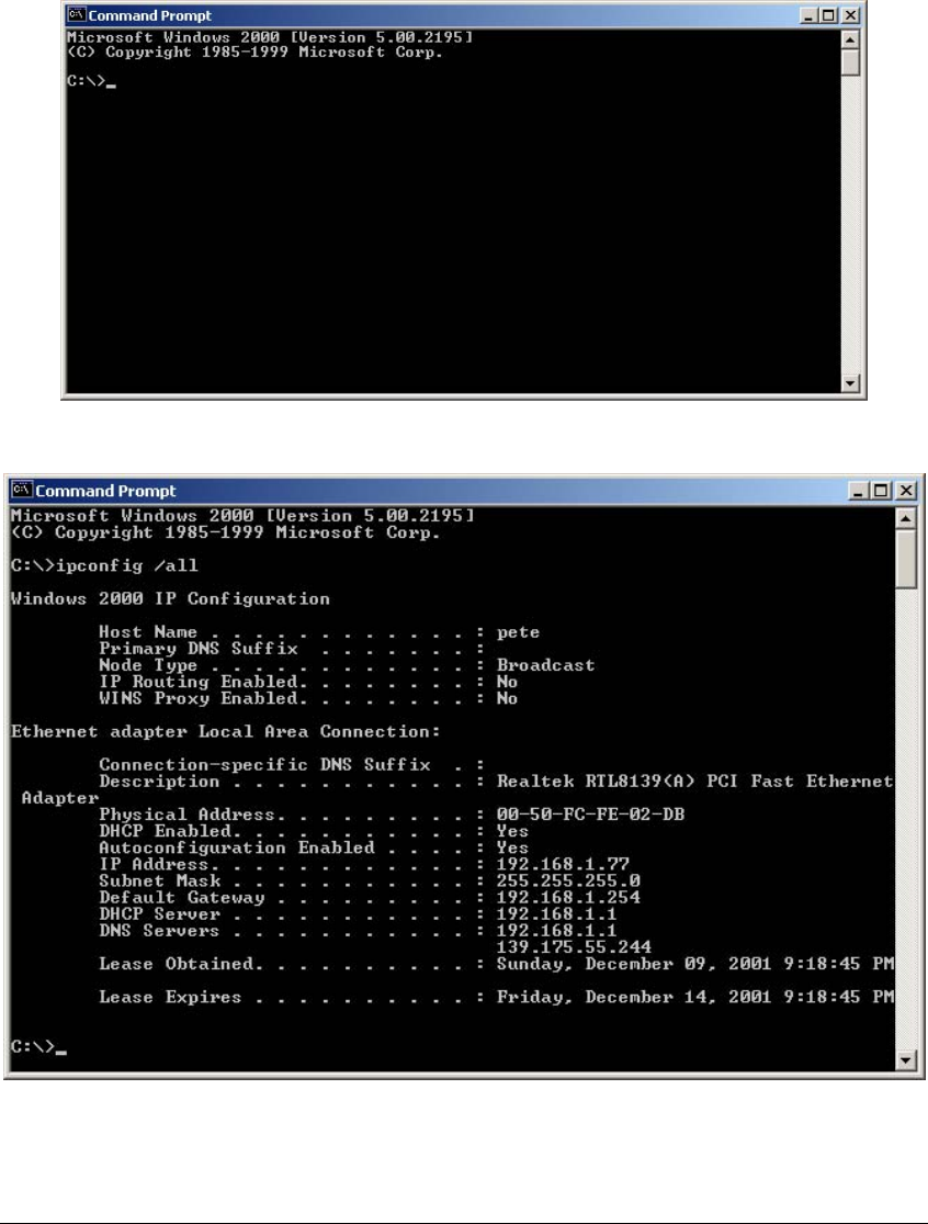
How to Manually find your PC’s IP and MAC address
1) In Window’s open the Command Prompt program
2) Type Ipconfig /all and <enter>
• Your PC’s IP address is the one entitled IP address (192.168.1.77)
• The router’s IP address is the one entitled Default Gateway (192.168.1.254)
• Your PC’s MAC Address is the one entitled Physical Address (00-50-FC-FE-02-DB)

101
Glossary
Default Gateway (Router): Every non-router IP device needs to configure a default gateway’s IP
address. When the device sends out an IP packet, if the destination is not on the same network,
the device has to send the packet to its default gateway, which will then send it out towards the
destination.
DHCP: Dynamic Host Configuration Protocol. This protocol automatically gives every computer
on your home network an IP address.
DNS Server IP Address: DNS stands for Domain Name System, which allows Internet servers to
have a domain name (such as www.Broadbandrouter.com) and one or more IP addresses (such
as 192.34.45.8). A DNS server keeps a database of Internet servers and their respective domain
names and IP addresses, so that when a domain name is requested (as in typing
"Broadbandrouter.com" into your Internet browser), the user is sent to the proper IP address. The
DNS server IP address used by the computers on your home network is the location of the DNS
server your ISP has assigned to you.
DSL Modem: DSL stands for Digital Subscriber Line. A DSL modem uses your existing phone
lines to transmit data at high speeds.
Ethernet: A standard for computer networks. Ethernet networks are connected by special cables
and hubs, and move data around at up to 10/100 million bits per second (Mbps).
Idle Timeout: Idle Timeout is designed so that after there is no traffic to the Internet for a pre-
configured amount of time, the connection will automatically be disconnected.
IP Address and Network (Subnet) Mask: IP stands for Internet Protocol. An IP address consists
of a series of four numbers separated by periods, that identifies a single, unique Internet
computer host in an IP network. Example: 192.168.2.1. It consists of 2 portions: the IP network
address, and the host identifier.
The IP address is a 32-bit binary pattern, which can be represented as four cascaded decimal
numbers separated by “.”: aaa.aaa.aaa.aaa, where each “aaa” can be anything from 000 to 255,
or as four cascaded binary numbers separated by “.”: bbbbbbbb.bbbbbbbb.bbbbbbbb.bbbbbbbb,
where each “b” can either be 0 or 1.
A network mask is also a 32-bit binary pattern, and consists of consecutive leading
1’s followed by consecutive trailing 0’s, such as
11111111.11111111.11111111.00000000. Therefore sometimes a network mask can also be
described simply as “x” number of leading 1’s.
When both are represented side by side in their binary forms, all bits in the IP address that
correspond to 1’s in the network mask become part of the IP network address, and the remaining
bits correspond to the host ID.
For example, if the IP address for a device is, in its binary form,
11011001.10110000.10010000.00000111, and if its network mask is,
11111111.11111111.11110000.00000000
It means the device’s network address is
11011001.10110000.10010000.00000000, and its host ID is,
00000000.00000000.00000000.00000111. This is a convenient and efficient method for routers
to route IP packets to their destination.
ISP Gateway Address: (see ISP for definition). The ISP Gateway Address is an IP address for
the Internet router located at the ISP's office.
102
ISP: Internet Service Provider. An ISP is a business that provides connectivity to the Internet for
individuals and other businesses or organizations.
LAN: Local Area Network. A LAN is a group of computers and devices connected together in a
relatively small area (such as a house or an office). Your home network is considered a LAN.
MAC Address: MAC stands for Media Access Control. A MAC address is the hardware address
of a device connected to a network. The MAC address is a unique identifier for a device with an
Ethernet interface. It is comprised of two parts: 3 bytes of data that corresponds to the
Manufacturer ID (unique for each manufacturer), plus 3 bytes that are often used as the product’s
serial number.
NAT: Network Address Translation. This process allows all of the computers on your home
network to use one IP address. Using the broadband router’s NAT capability, you can access the
Internet from any computer on your home network without having to purchase more IP addresses
from your ISP.
Port: Network Clients (LAN PC) uses port numbers to distinguish one network
application/protocol over another. Below is a list of common applications and protocol/port
numbers:
Application Protocol Port Number
Telnet TCP 23
FTP TCP 21
SMTP TCP 25
POP3 TCP 110
H.323 TCP 1720
SNMP UCP 161
SNMP Trap UDP 162
HTTP TCP 80
PPTP TCP 1723
PC Anywhere TCP 5631
PC Anywhere UDP 5632
PPPoE: Point-to-Point Protocol over Ethernet. Point-to-Point Protocol is a secure data
transmission method originally created for dial-up connections; PPPoE is for Ethernet
connections. PPPoE relies on two widely accepted standards, Ethernet and the Point-to-Point
Protocol. It is a communications protocol for transmitting information over Ethernet between
different manufacturers
Protocol: A protocol is a set of rules for interaction agreed upon between multiple parties so that
when they interface with each other based on such a protocol, the interpretation of their behavior
is well defined and can be made objectively, without confusion or misunderstanding.
Router: A router is an intelligent network device that forwards packets between different
networks based on network layer address information such as IP addresses.
Subnet Mask: A subnet mask, which may be a part of the TCP/IP information provided by your
ISP, is a set of four numbers (e.g. 255.255.255.0) configured like an IP address. It is used to

103
create IP address numbers used only within a particular network (as opposed to valid IP address
numbers recognized by the Internet, which must be assigned by InterNIC).
TCP/IP, UDP: Transmission Control Protocol/Internet Protocol (TCP/IP) and Unreliable Datagram
Protocol (UDP). TCP/IP is the standard protocol for data transmission over the Internet. Both TCP
and UDP are transport layer protocol. TCP performs proper error detection and error recovery,
and thus is reliable. UDP on the other hand is not reliable. They both run on top of the IP (Internet
Protocol), a network layer protocol.
WAN: Wide Area Network. A network that connects computers located in geographically
separate areas (e.g. different buildings, cities, countries). The Internet is a wide area network.
Web-based management Graphical User Interface (GUI): Many devices support a graphical
user interface that is based on the web browser. This means the user can use the familiar
Netscape or Microsoft Internet Explorer to Control/configure or monitor the device being managed.
Federal Communication Commission Interference Statement
This equipment has been tested and found to comply with the limits for
a Class B digital device, pursuant to Part 15 of the FCC Rules. These
limits are designed to provide reasonable protection against harmful
interference in a residential installation. This equipment generates,
uses and can radiate radio frequency energy and, if not installed and
used in accordance with the instructions, may cause harmful
interference to radio communications. However, there is no guarantee
that interference will not occur in a particular installation. If this
equipment does cause harmful interference to radio or television
reception, which can be determined by turning the equipment off and on,
the user is encouraged to try to correct the interference by one of the
following measures:
- Reorient or relocate the receiving antenna.
- Increase the separation between the equipment and receiver.
- Connect the equipment into an outlet on a circuit different from that
to which the receiver is connected.
- Consult the dealer or an experienced radio/TV technician for help.
FCC Caution: Any changes or modifications not expressly approved by
the party responsible for compliance could void the user's authority to
operate this equipment.
This device complies with Part 15 of the FCC Rules. Operation is subject to the
following two conditions: (1) This device may not cause harmful interference,
and (2) this device must accept any interference received, including
interference that may cause undesired operation.
IMPORTANT NOTE:
FCC Radiation Exposure Statement:
This equipment complies with FCC radiation exposure limits set forth for
an uncontrolled environment. This equipment should be installed and
operated with minimum distance 20cm between the radiator & your
body.
This transmitter must not be co-located or operating in conjunction with
any other antenna or transmitter.