Edimax Technology Co 9562100910 Wireless 11n Mini Router User Manual Edimax
Edimax Technology Co Ltd Wireless 11n Mini Router Edimax
UserManual.wiki
>
Edimax Technology Co
>
9562100910 User Manual
user manual
Navigation menu
Upload a User Manual
Namespaces
Wiki Guide
HTML
PDF
Info
Views
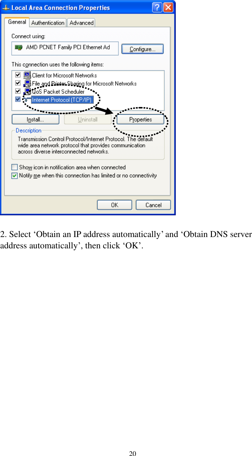
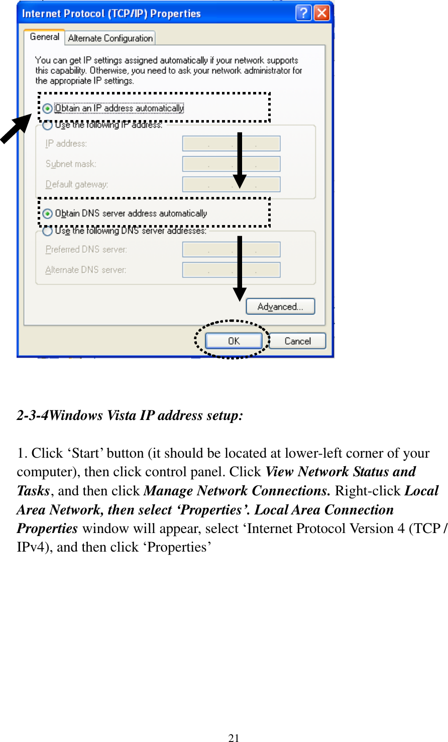
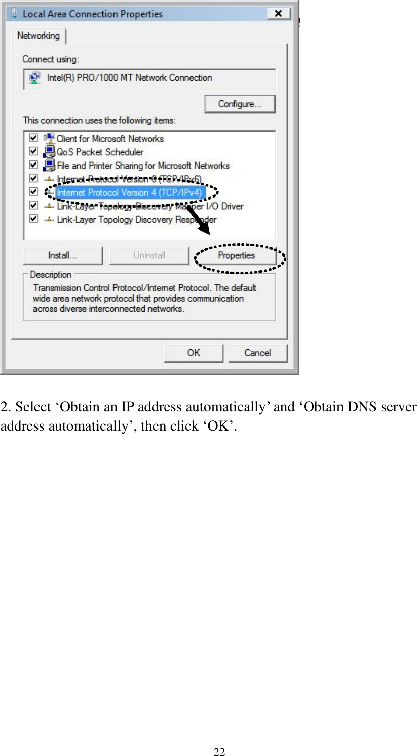
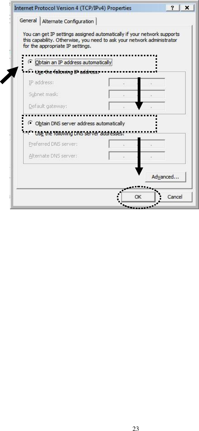
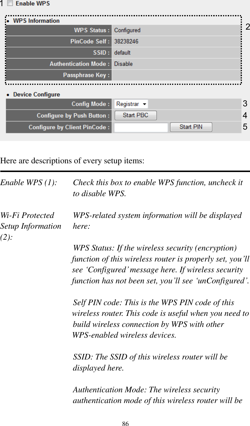
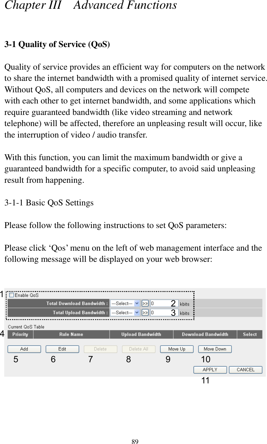
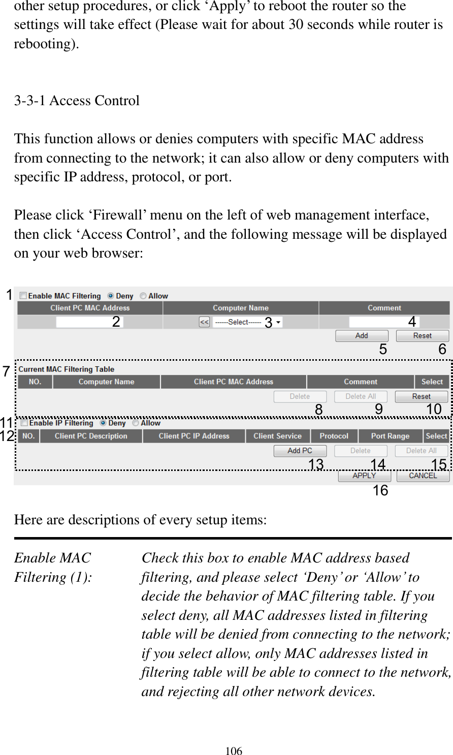
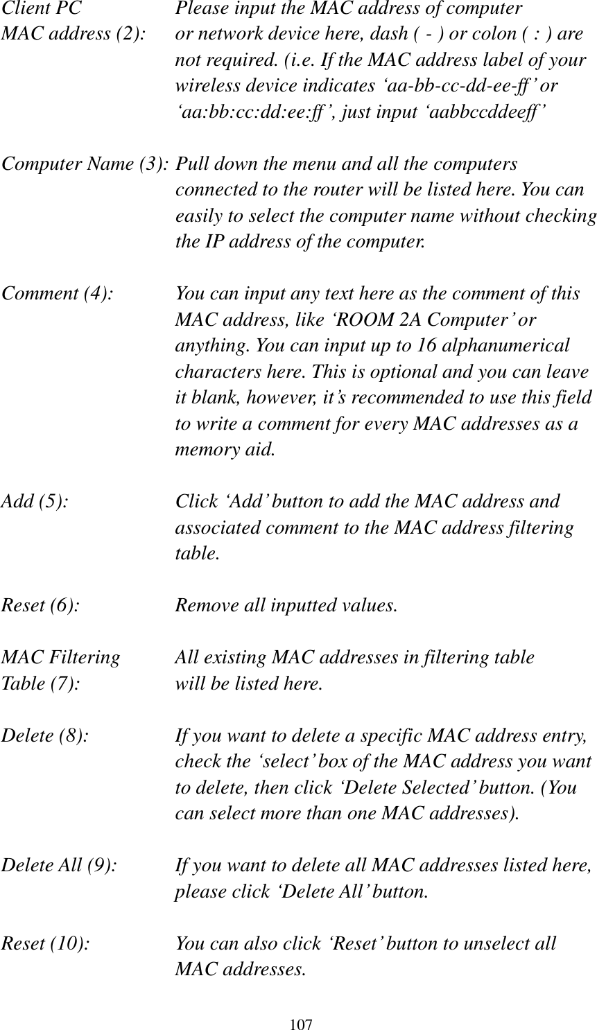
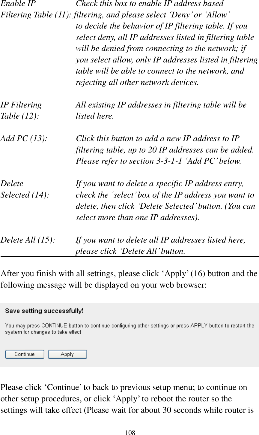
User Manual
Discussion / Help
Navigation