Edimax Technology Co 9570840711 802.11g Wireless LAN ADSL2+Router User Manual
Edimax Technology Co Ltd 802.11g Wireless LAN ADSL2+Router
UserManual.wiki
>
Edimax Technology Co
>
9570840711 User Manual
Users Manual
Navigation menu
Upload a User Manual
Namespaces
Wiki Guide
HTML
PDF
Info
Views
User Manual
Discussion / Help
Navigation
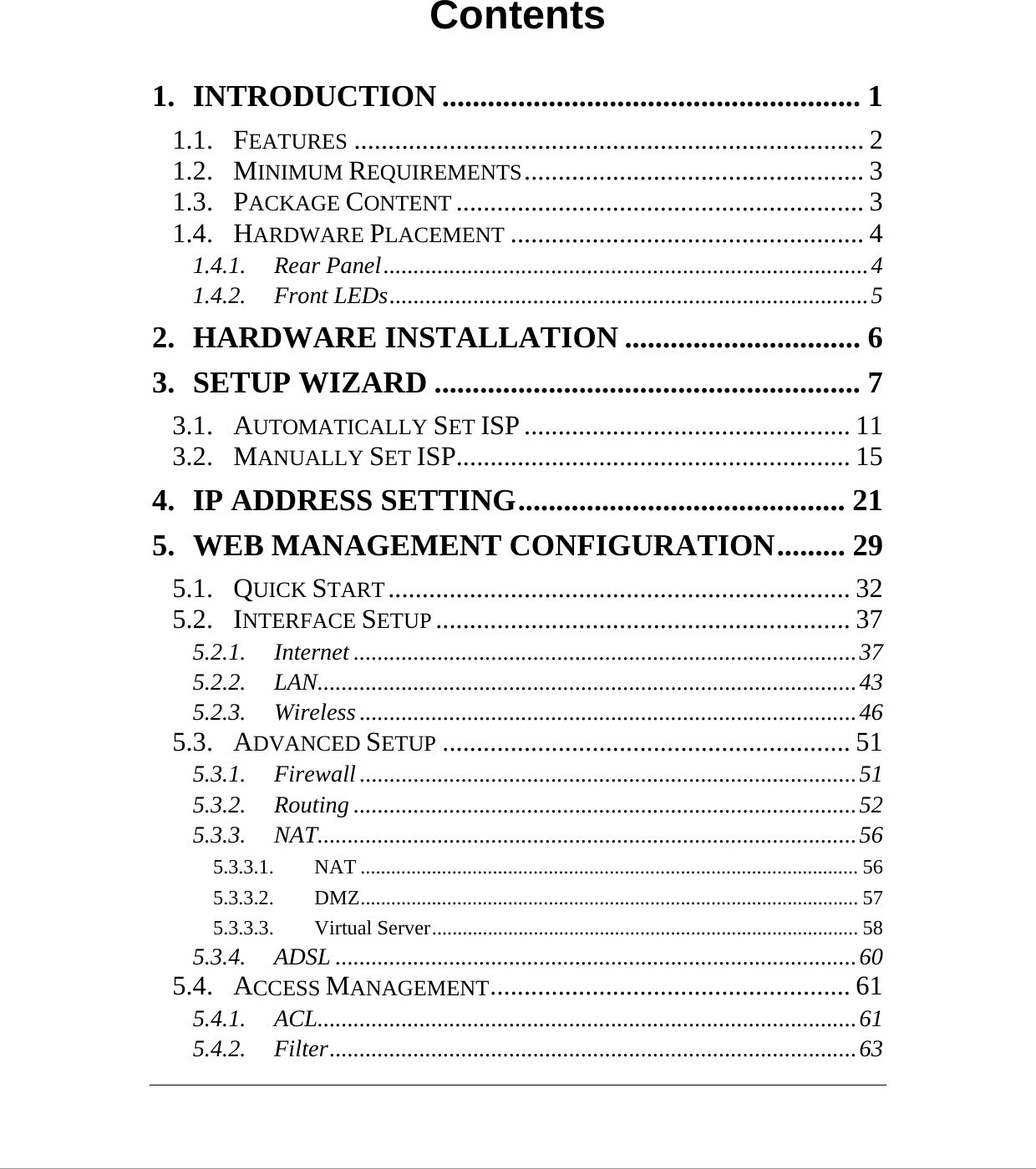

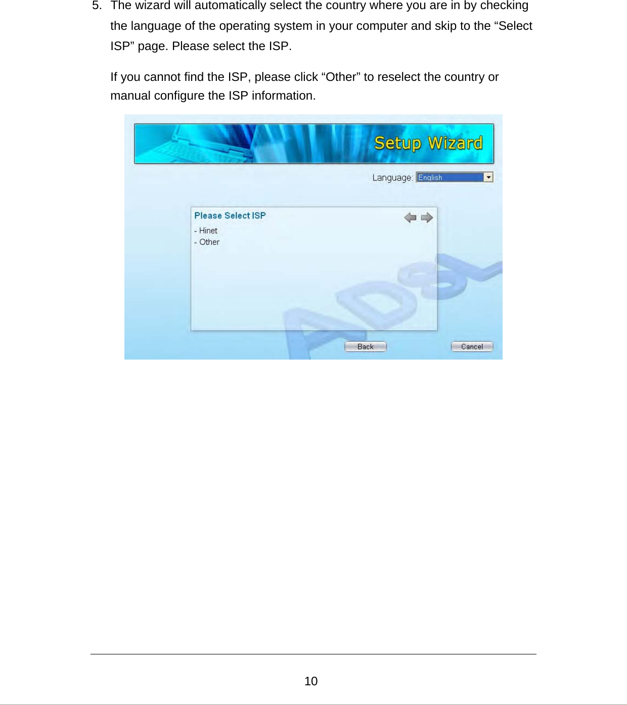
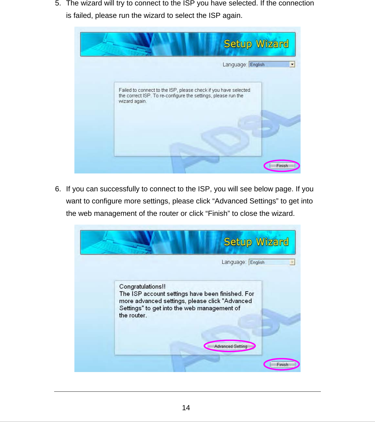
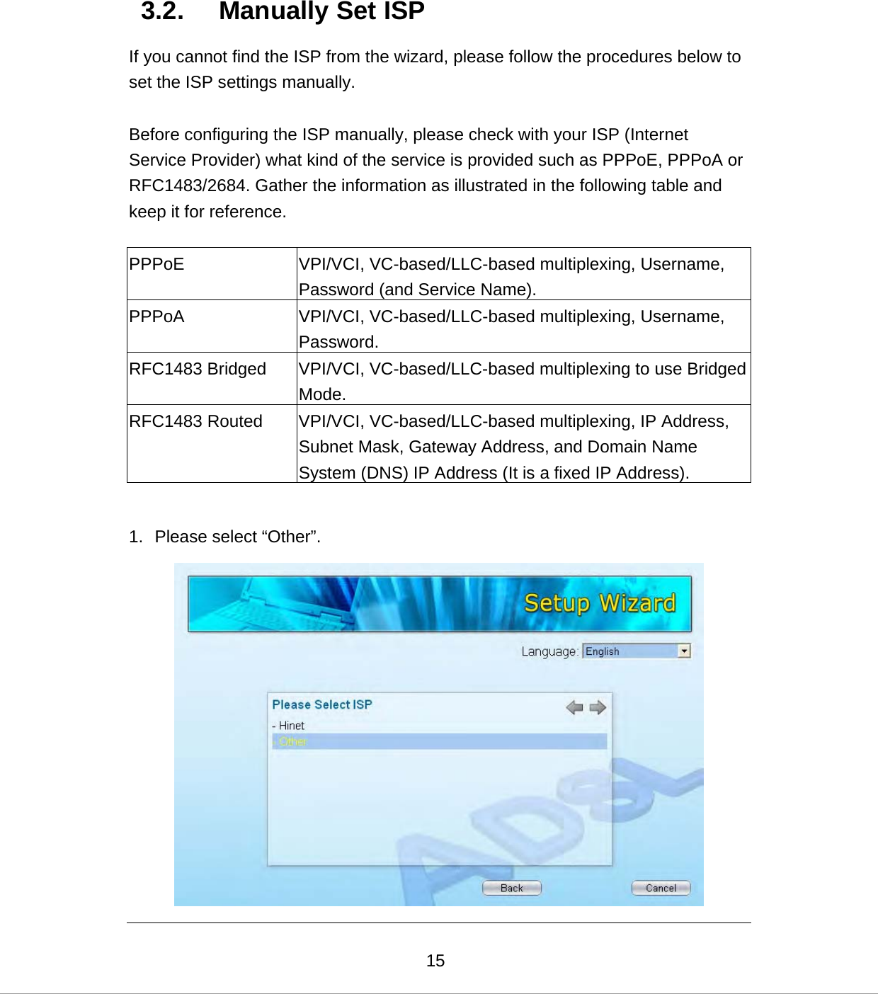
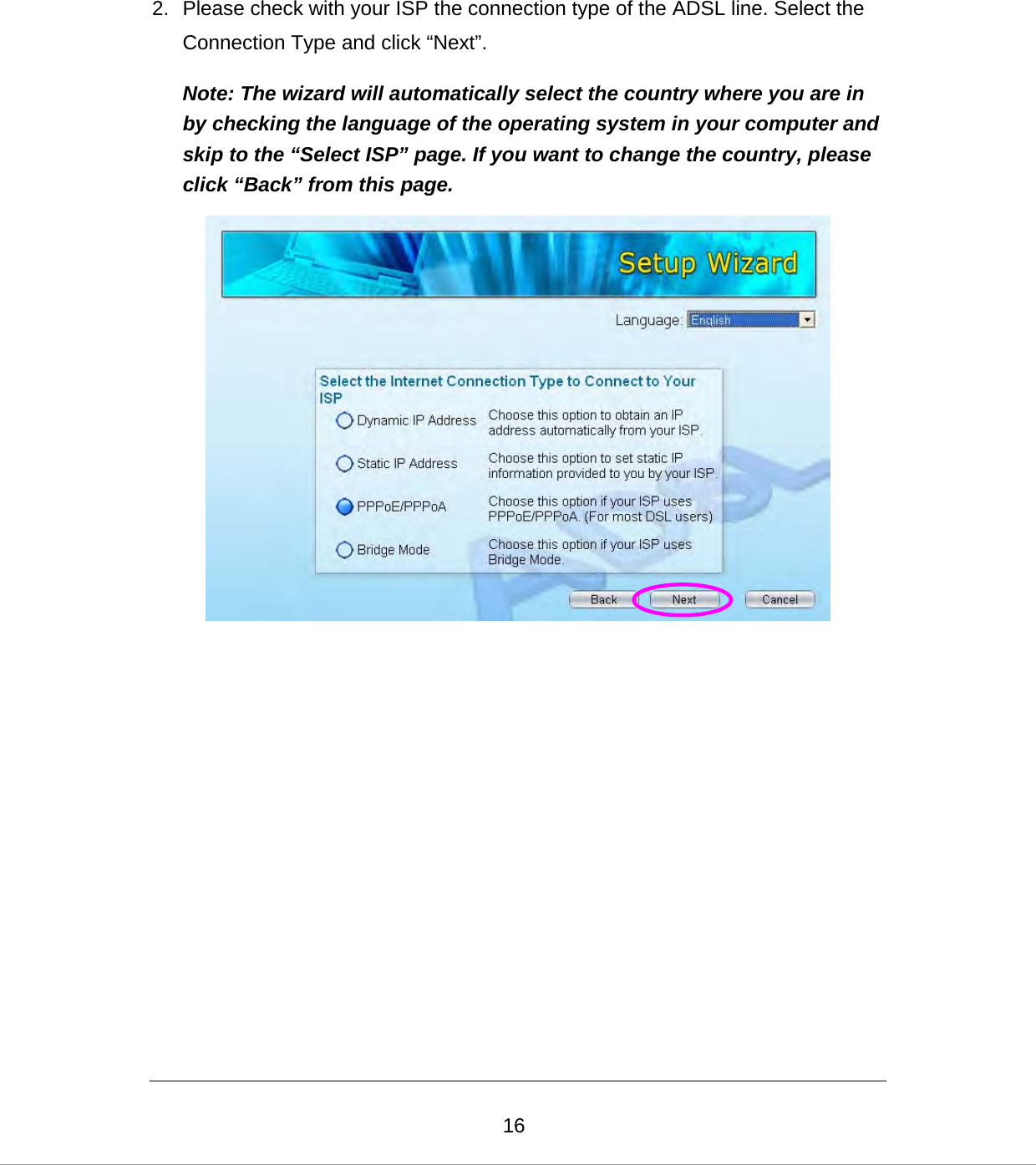
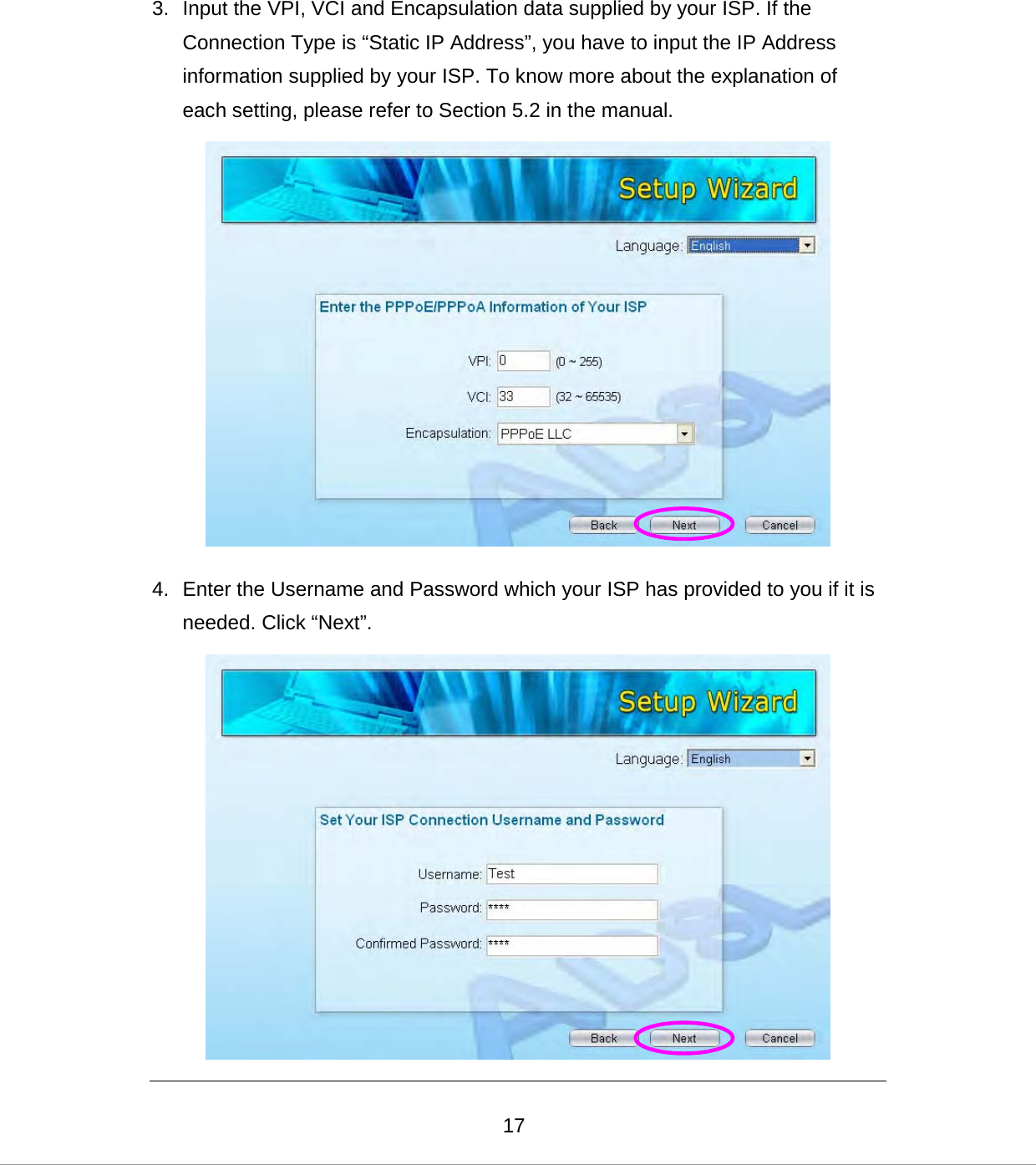
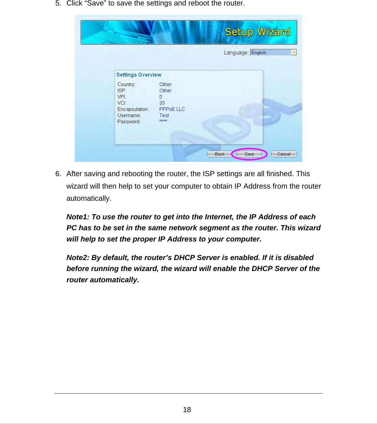
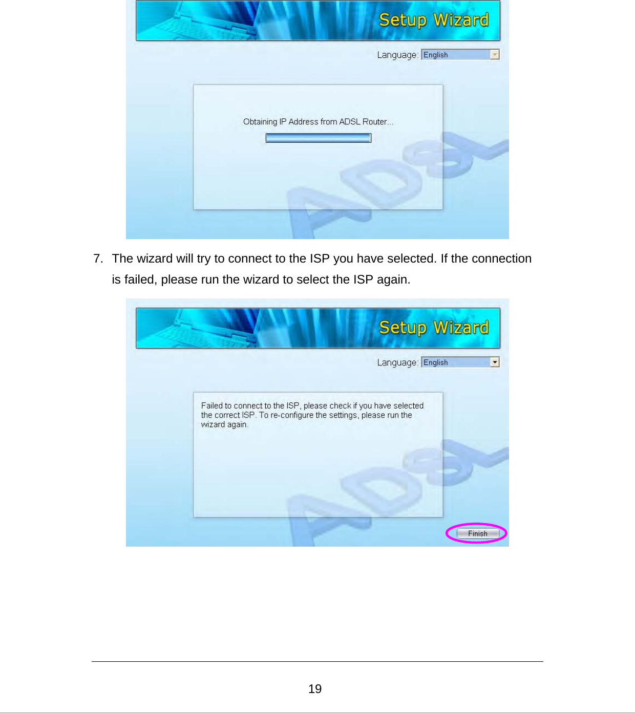
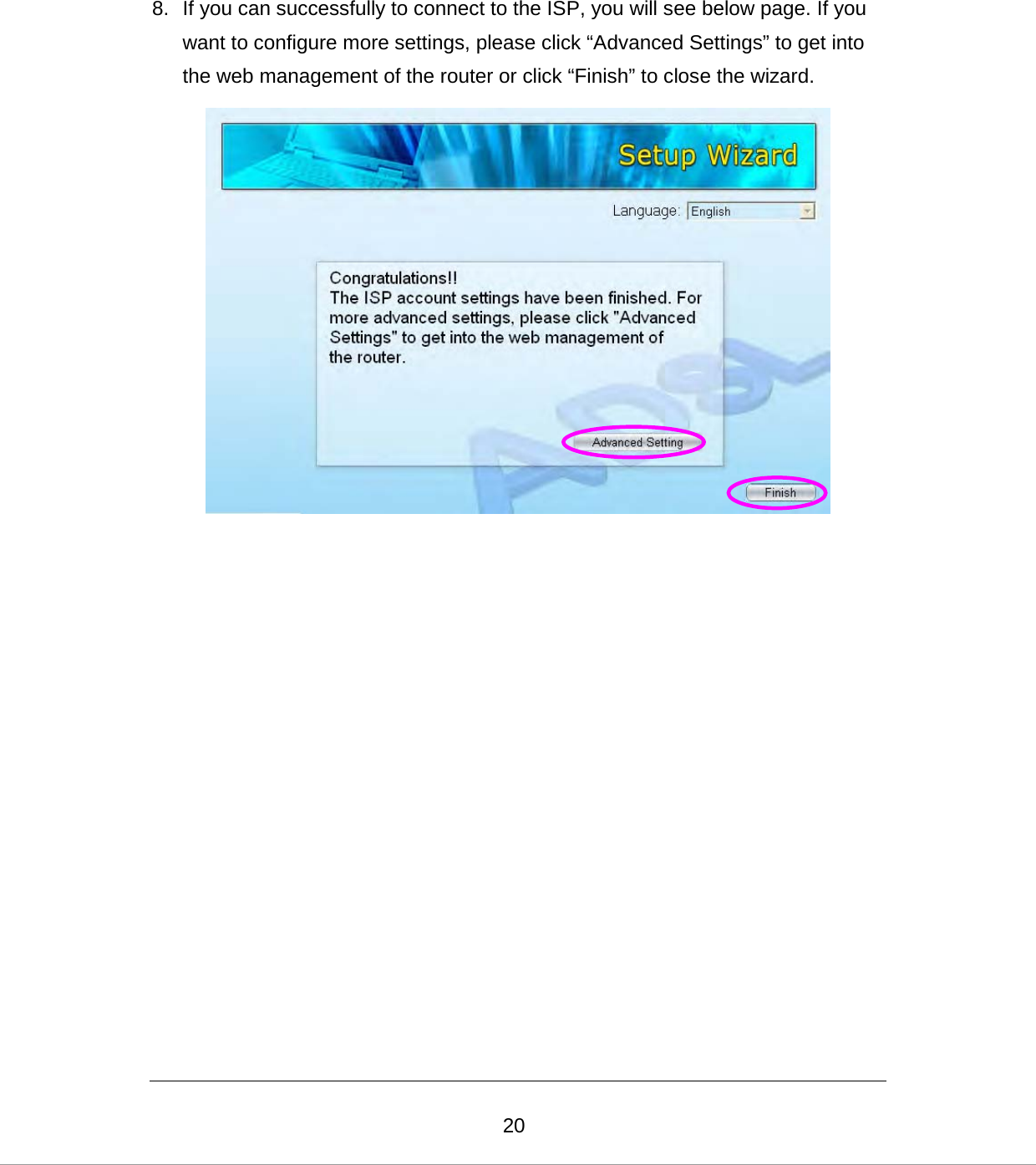
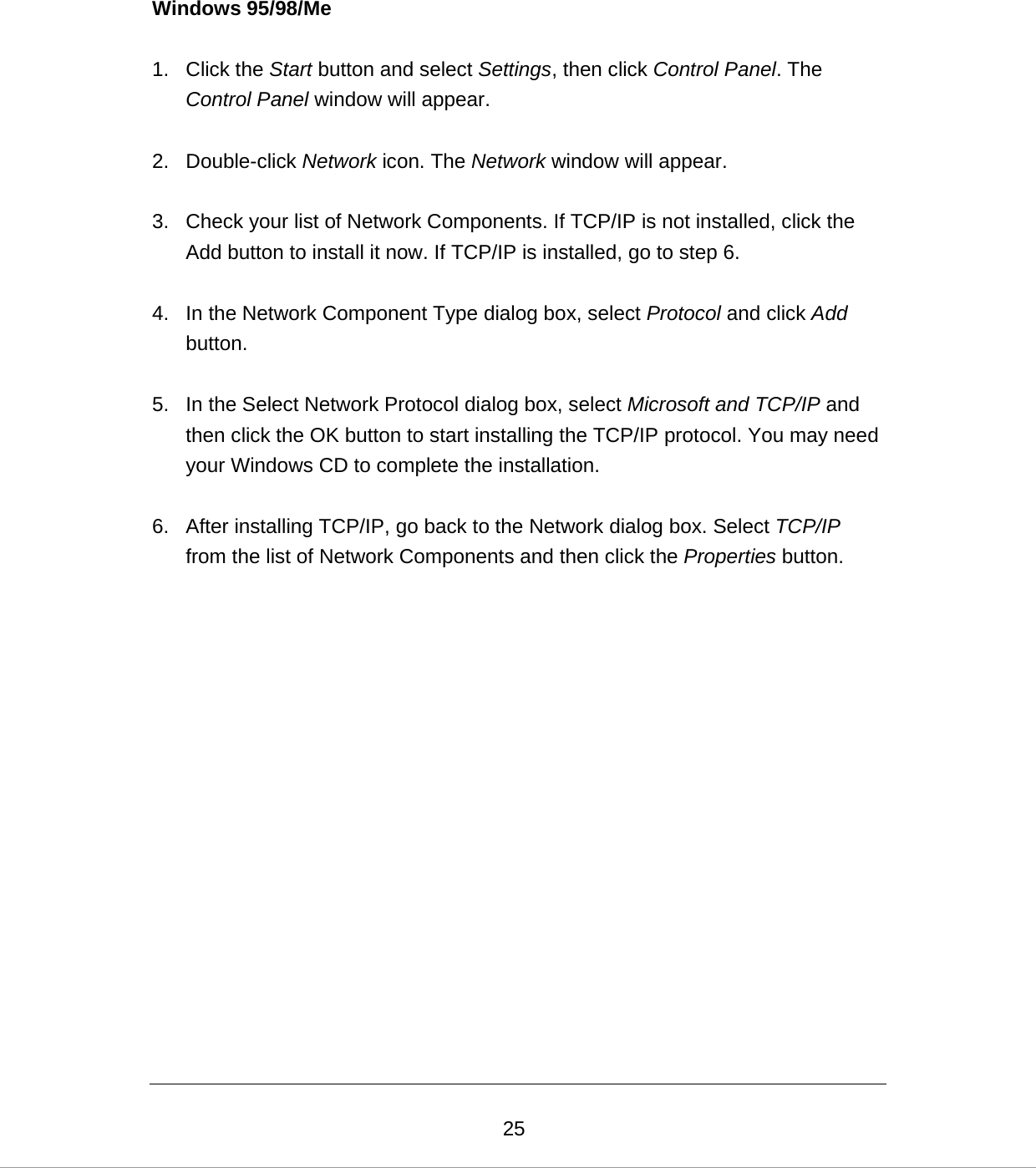
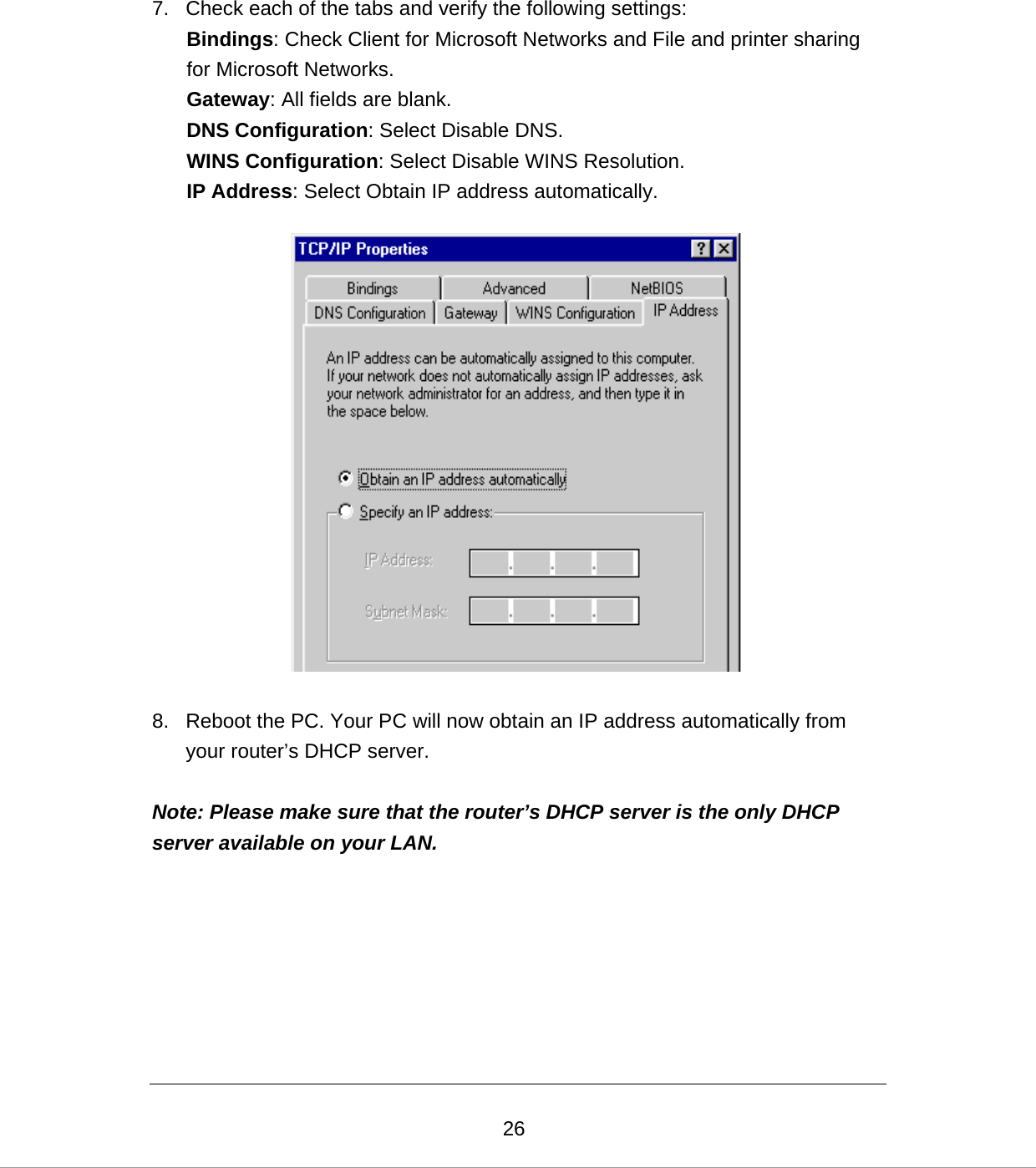
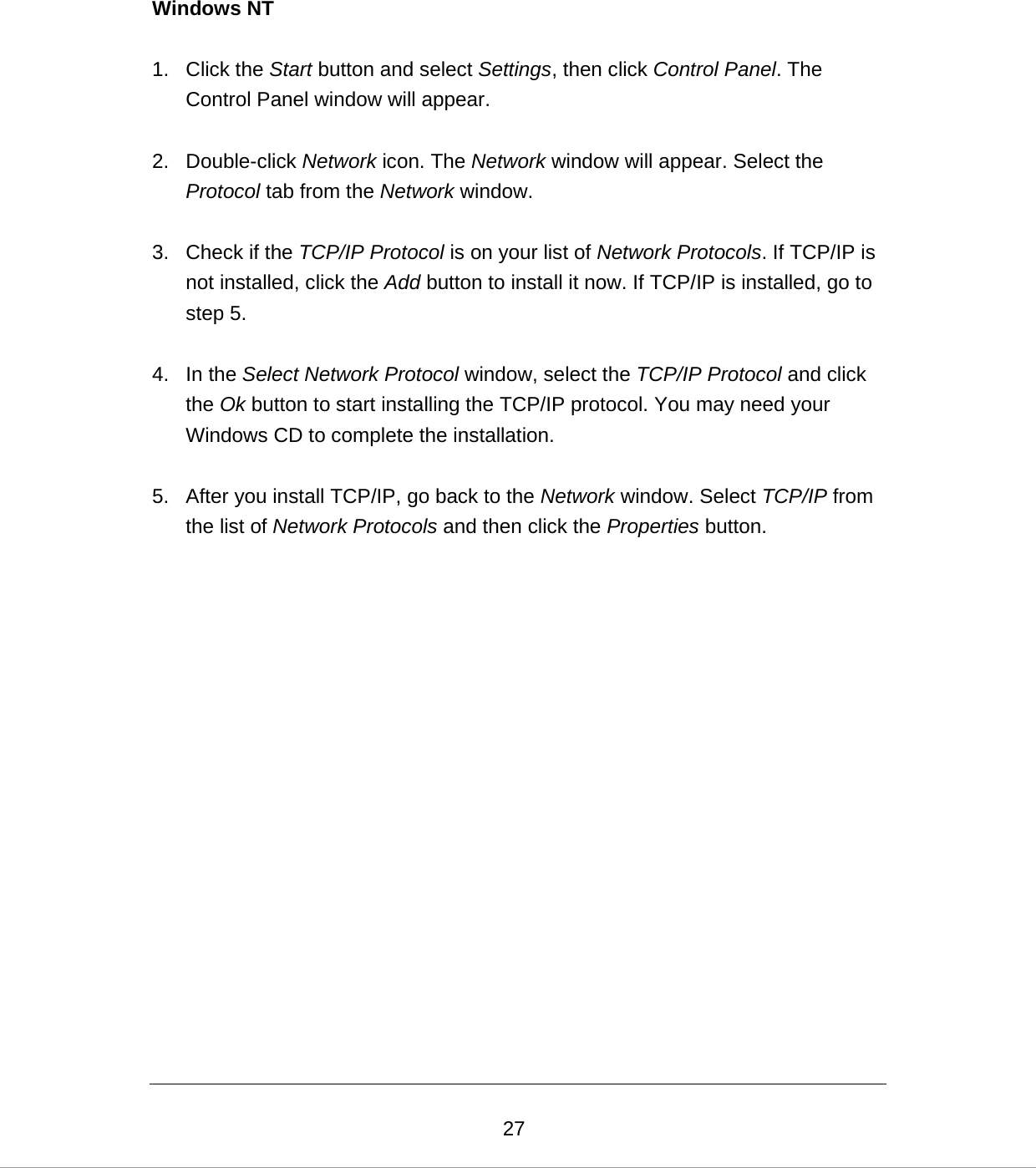
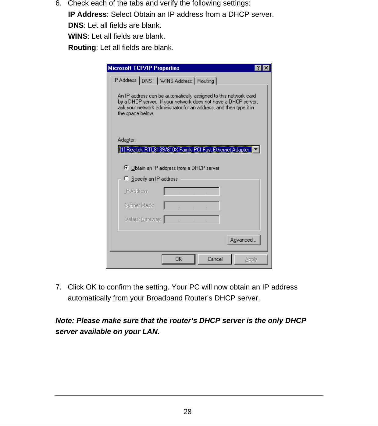
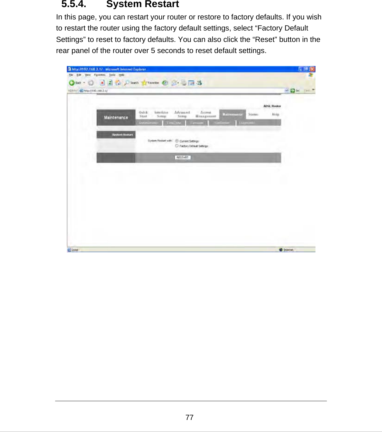
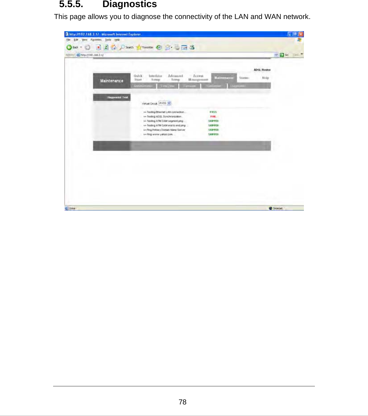
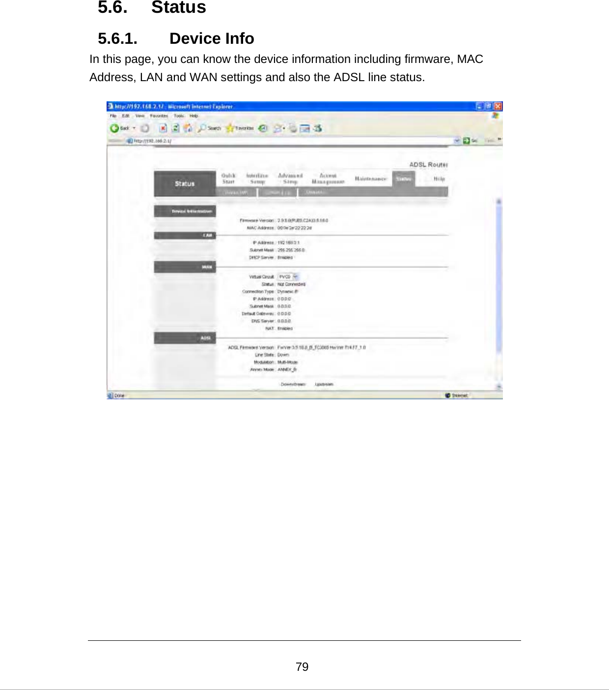
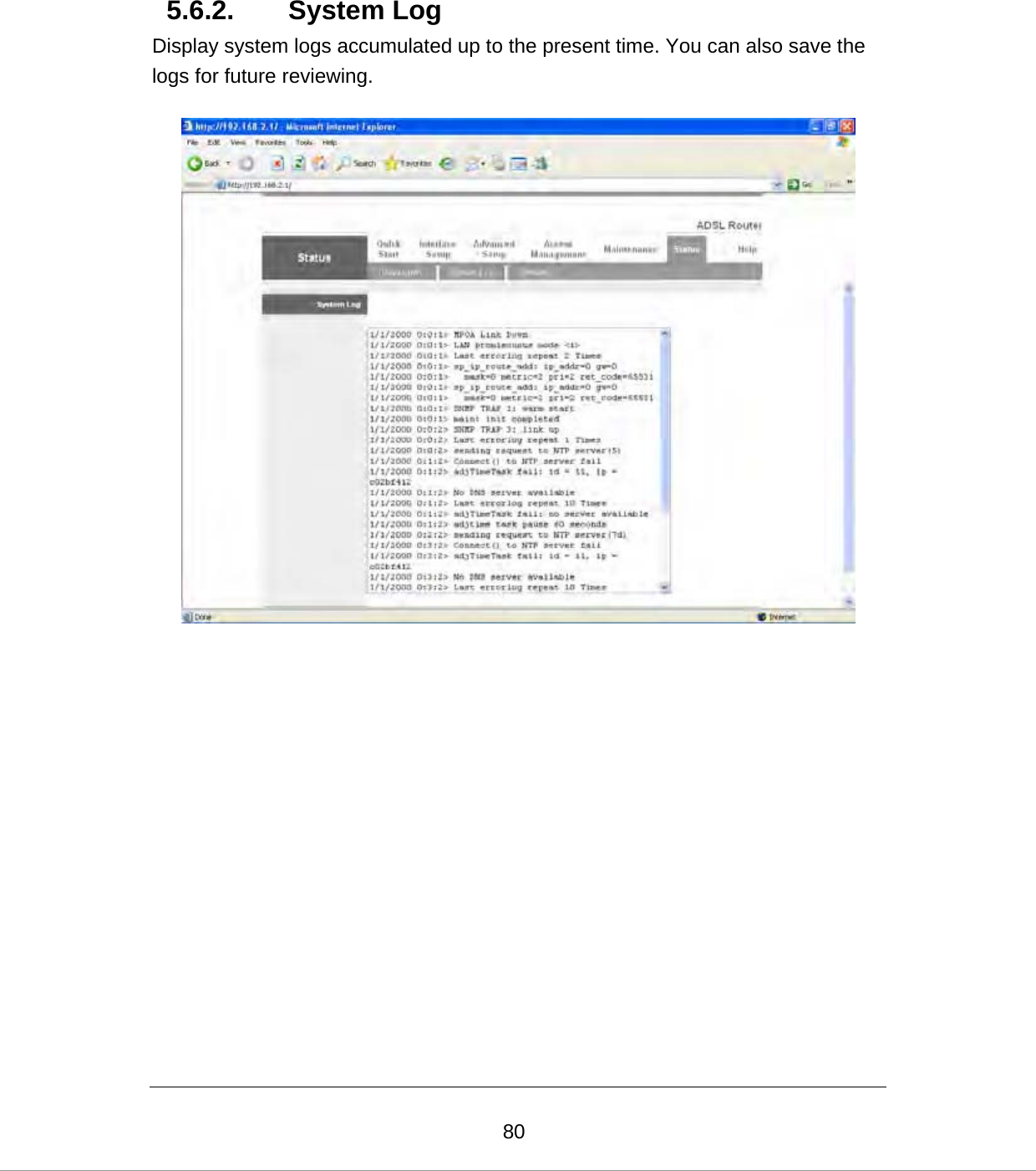
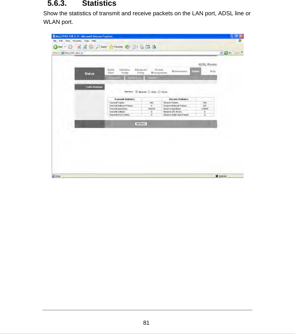
![214. IP Address Setting Using the router to get into the Internet, the PCs in the network must have Ethernet adapter installed and be connected to the router either directly or through a hub or switch. The TCP/IP protocol of each PC has to been installed and the IP Address of each PC has to be set in the same subnet as the router. The router’s default IP Address is 192.168.2.1 and the subnet mask is 255.255.255.0. PCs can be configured to obtain IP Address automatically through the DHCP Server of the router or a fixed IP Address in order to be in the same subnet as the router. By default, the DHCP Server of the router is enabled and will dispatch IP Address to PC from 192.168.2.100 to 192.168.2.200. It is strongly recommended to set obtaining IP address automatically. This section shows you how to configure your PC’s so that it can obtain an IP address automatically for either Windows 95/98/Me, 2000 or NT operating systems. For other operating systems (Macintosh, Sun, etc.), please follow the manual of the operating systems. The following is a step-by-step illustration on how to configure your PC to obtain an IP address automatically for Windows XP, Windows 2000, Windows 95/98/Me, and Windows NT. Windows XP 1. Click the Start button and select Control Panel and then double click Network Connections. The Network Connections window will appear. 2. Right click on the Local Area Connection icon and select Properties. The Local Area Connection window will appear. 3. Check your list of Network Components. You should see Internet Protocol [TCP/IP] on your list. Select it and click the Properties button.](https://usermanual.wiki/Edimax-Technology-Co/9570840711/User-Guide-825100-Page-29.png)
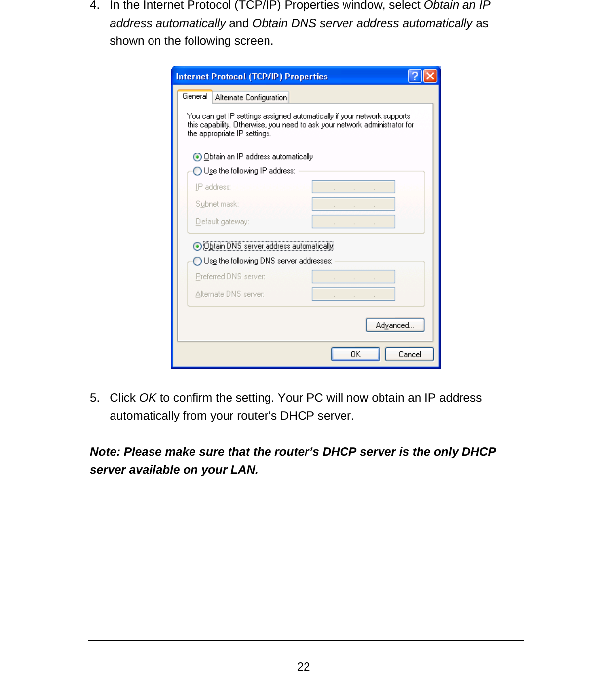
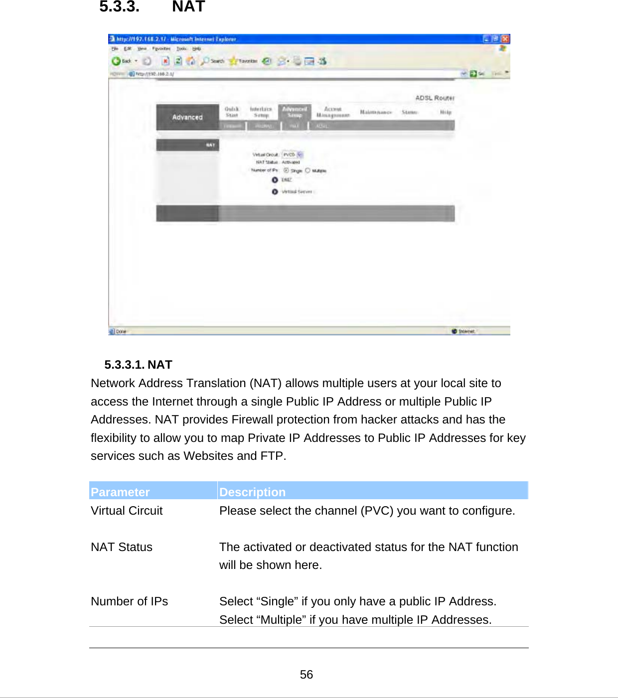
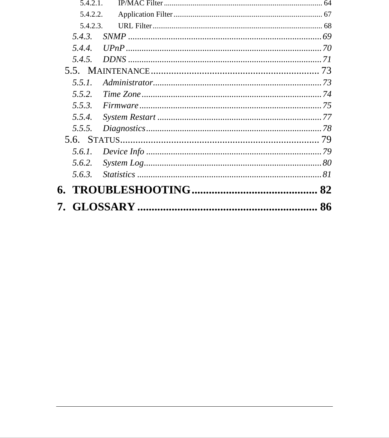
![23Windows 2000 1. Click the Start button and select Settings, then click Control Panel. The Control Panel window will appear. 2. Double-click Network and Dial-up Connections icon. In the Network and Dial-up Connection window, double-click Local Area Connection icon. The Local Area Connection window will appear. 3. In the Local Area Connection window, click the Properties button. 4. Check your list of Network Components. You should see Internet Protocol [TCP/IP] on your list. Select it and click the Properties button. 5. In the Internet Protocol (TCP/IP) Properties window, select Obtain an IP address automatically and Obtain DNS server address automatically as shown on the following screen.](https://usermanual.wiki/Edimax-Technology-Co/9570840711/User-Guide-825100-Page-31.png)