Edimax Technology Co 9572661001 Wireless N ADSL 2/2+ Router User Manual
Edimax Technology Co Ltd Wireless N ADSL 2/2+ Router
UserManual.wiki
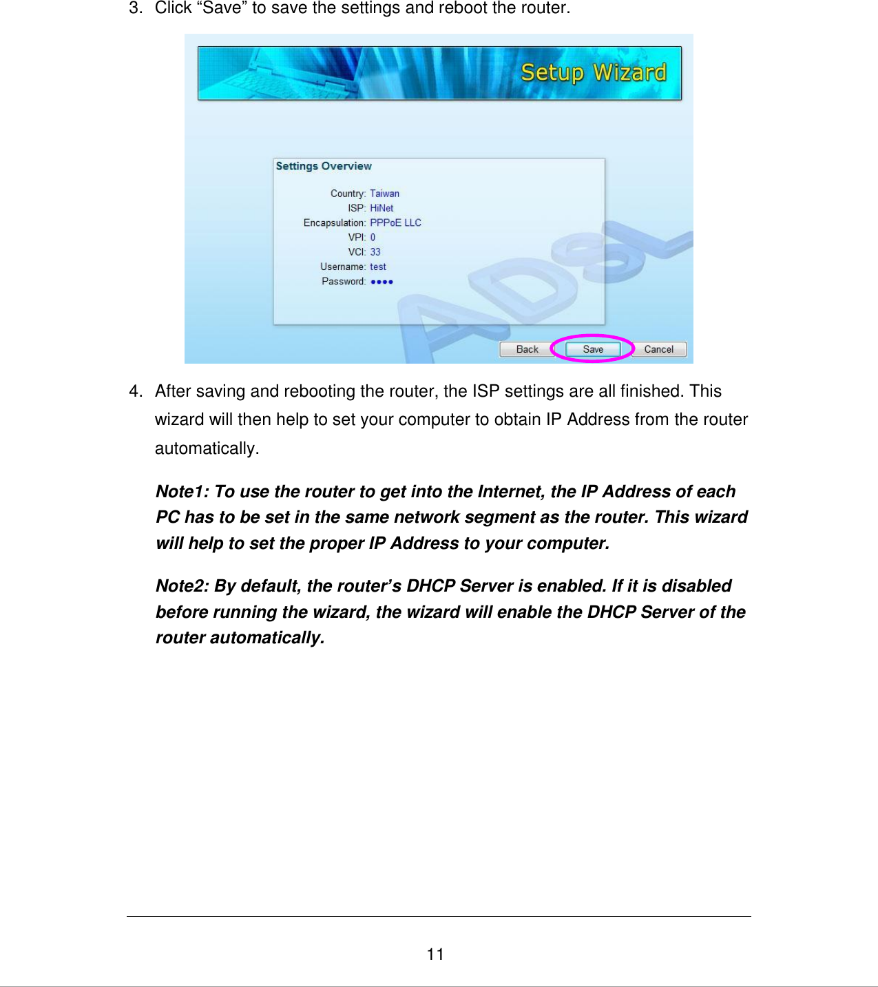
>
Edimax Technology Co
>
9572661001 User Manual
User Manual
Navigation menu
Upload a User Manual
Namespaces
Wiki Guide
HTML
PDF
Info
Views
User Manual
Discussion / Help
Navigation
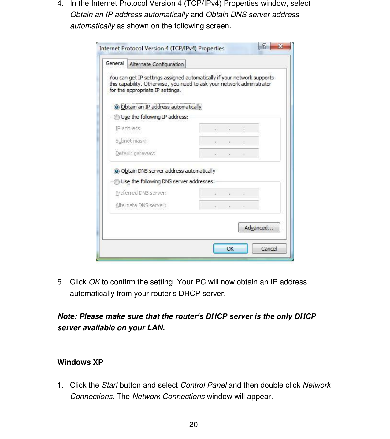
![21 2. Right click on the Local Area Connection icon and select Properties. The Local Area Connection window will appear. 3. Check your list of Network Components. You should see Internet Protocol [TCP/IP] on your list. Select it and click the Properties button. 4. In the Internet Protocol (TCP/IP) Properties window, select Obtain an IP address automatically and Obtain DNS server address automatically as shown on the following screen. 5. Click OK to confirm the setting. Your PC will now obtain an IP address automatically from your router‟s DHCP server. Note: Please make sure that the router’s DHCP server is the only DHCP server available on your LAN.](https://usermanual.wiki/Edimax-Technology-Co/9572661001/User-Guide-1308280-Page-30.png)
![22 Windows 2000 1. Click the Start button and select Settings, then click Control Panel. The Control Panel window will appear. 2. Double-click Network and Dial-up Connections icon. In the Network and Dial-up Connection window, double-click Local Area Connection icon. The Local Area Connection window will appear. 3. In the Local Area Connection window, click the Properties button. 4. Check your list of Network Components. You should see Internet Protocol [TCP/IP] on your list. Select it and click the Properties button. 5. In the Internet Protocol (TCP/IP) Properties window, select Obtain an IP address automatically and Obtain DNS server address automatically as shown on the following screen.](https://usermanual.wiki/Edimax-Technology-Co/9572661001/User-Guide-1308280-Page-31.png)