Edimax Technology Co 9573170406 WLAN USB ADAPTER User Manual EW 7317UG Manual
Edimax Technology Co Ltd WLAN USB ADAPTER EW 7317UG Manual
UserManual.wiki
>
Edimax Technology Co
>
9573170406 User Manual
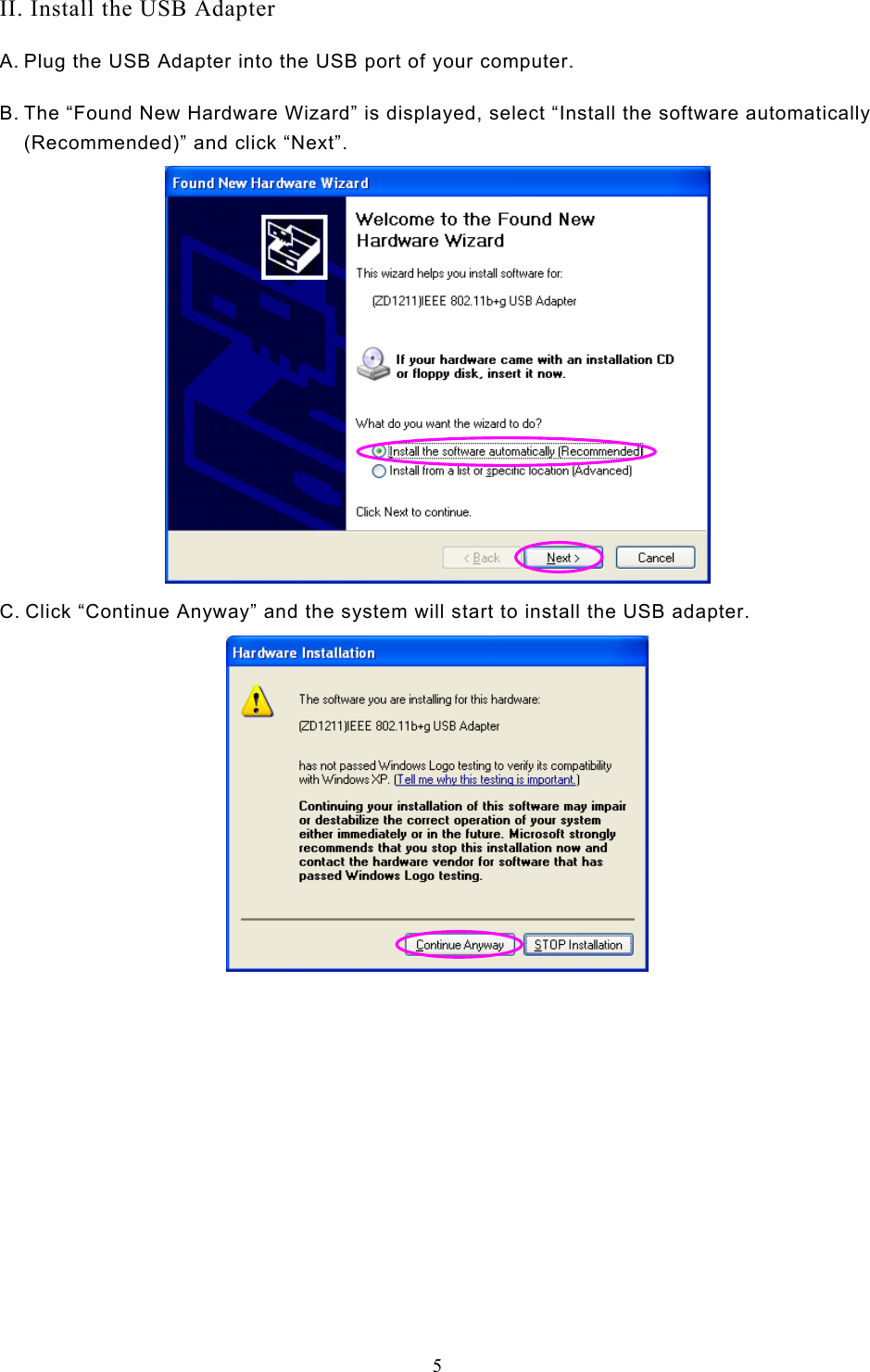
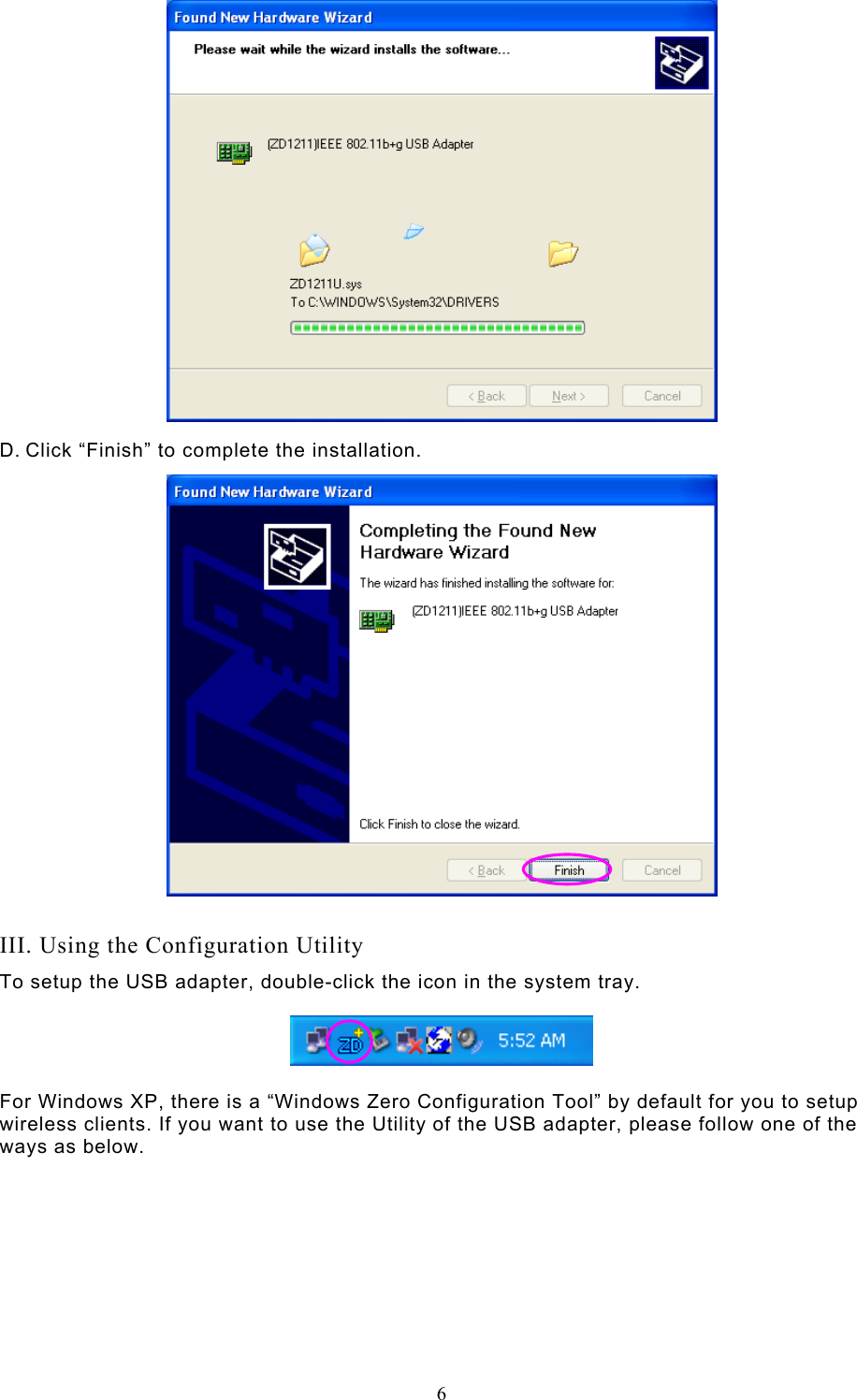
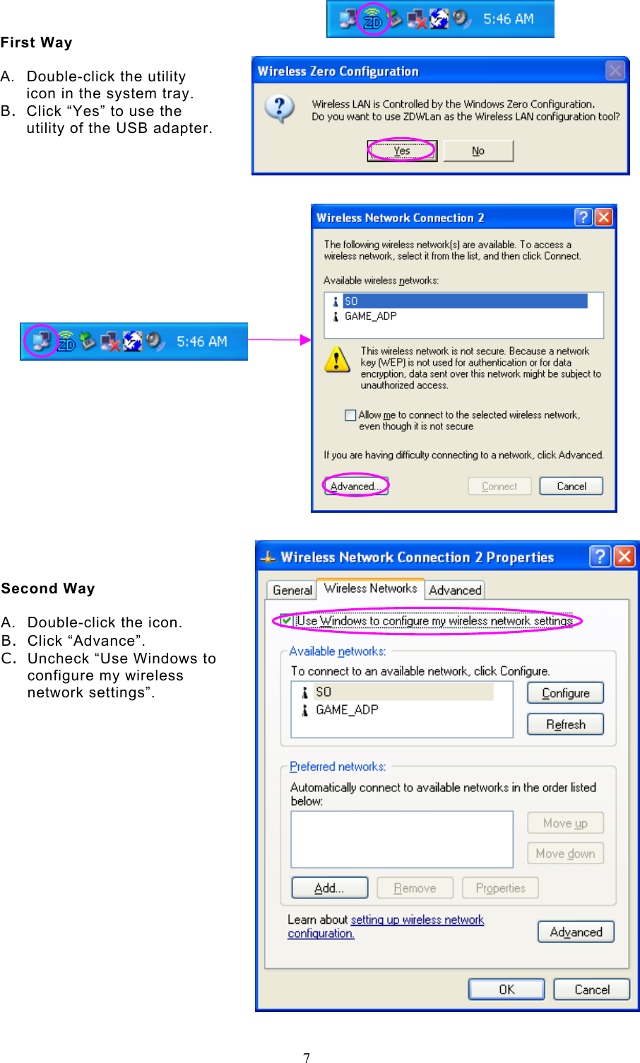
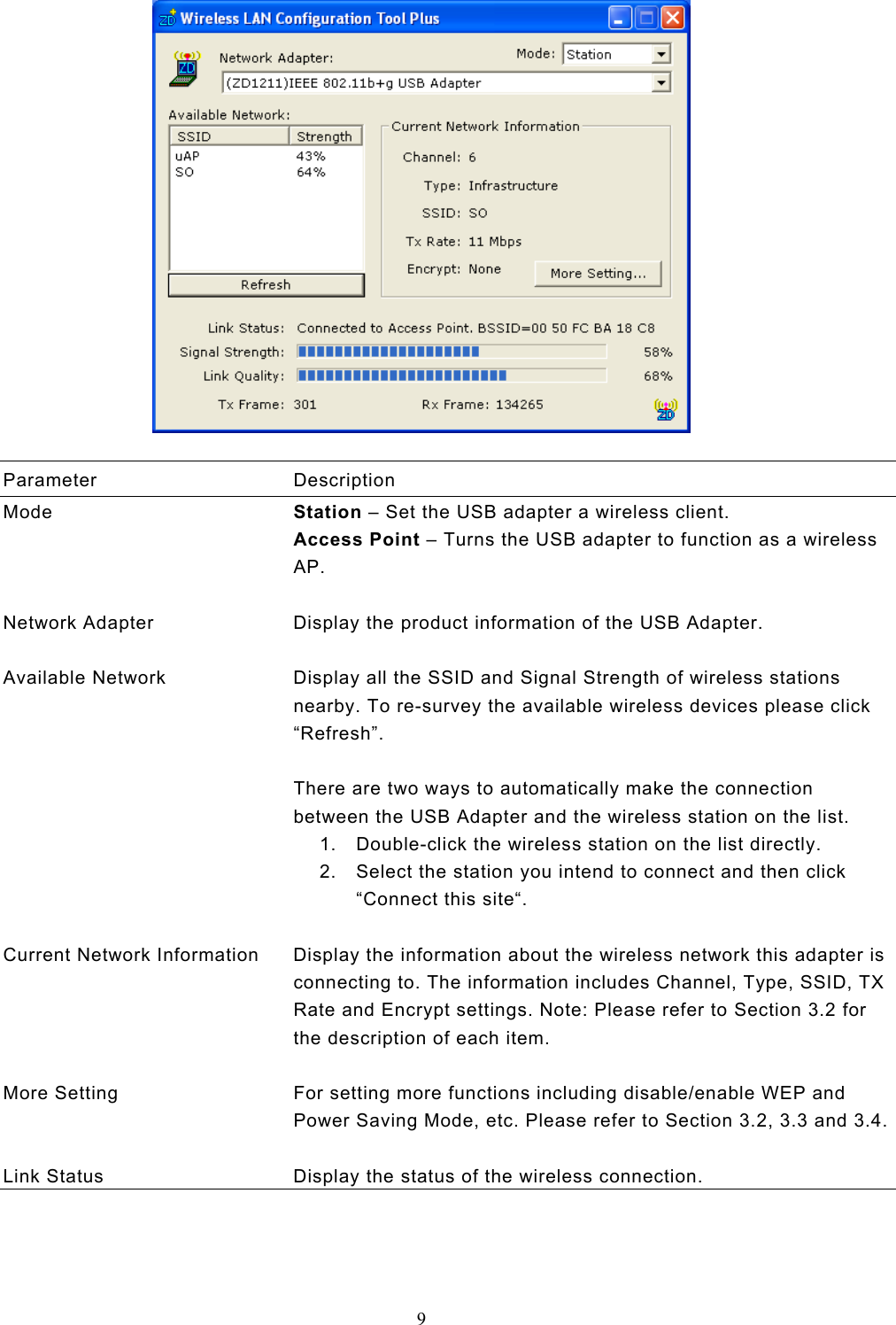
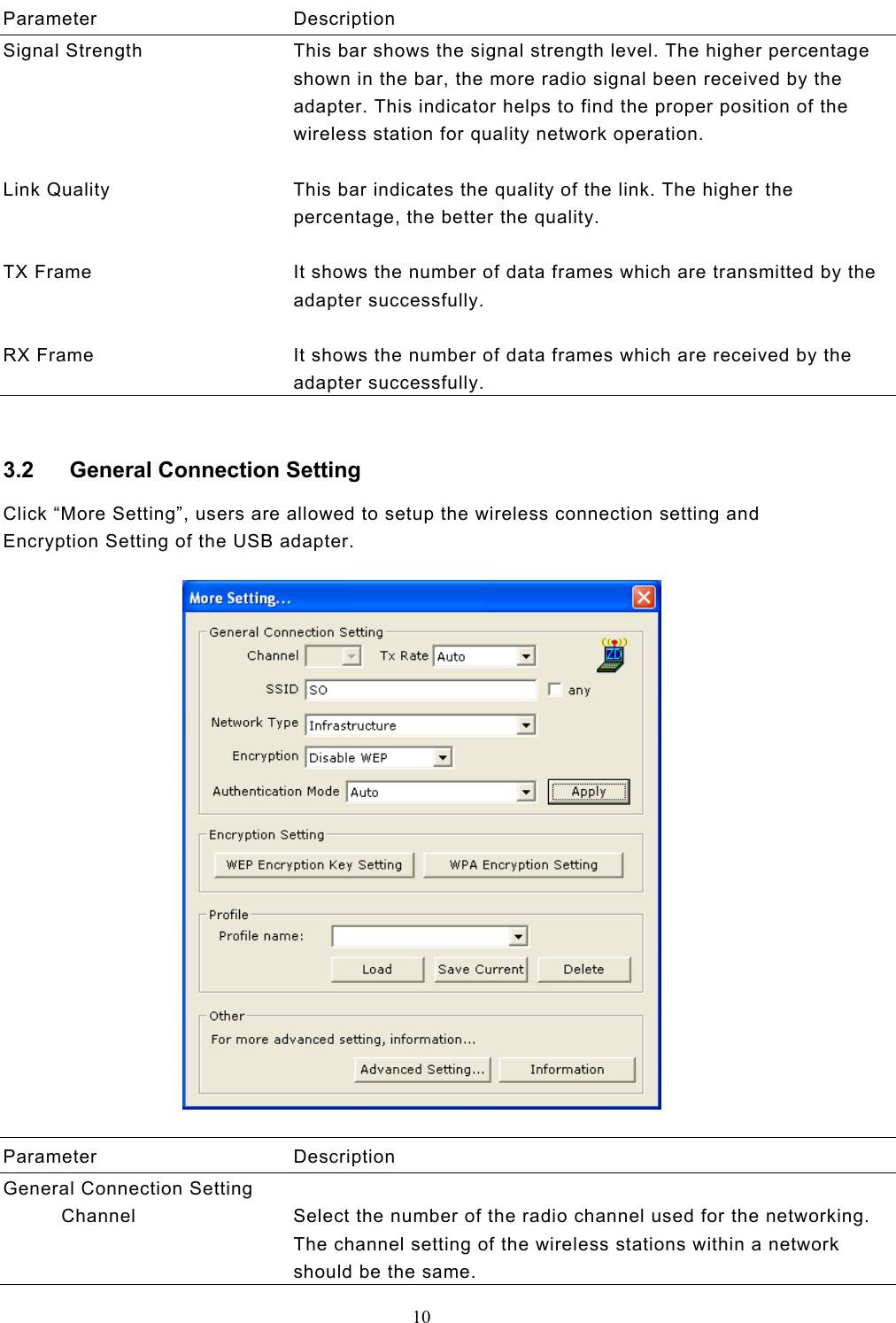
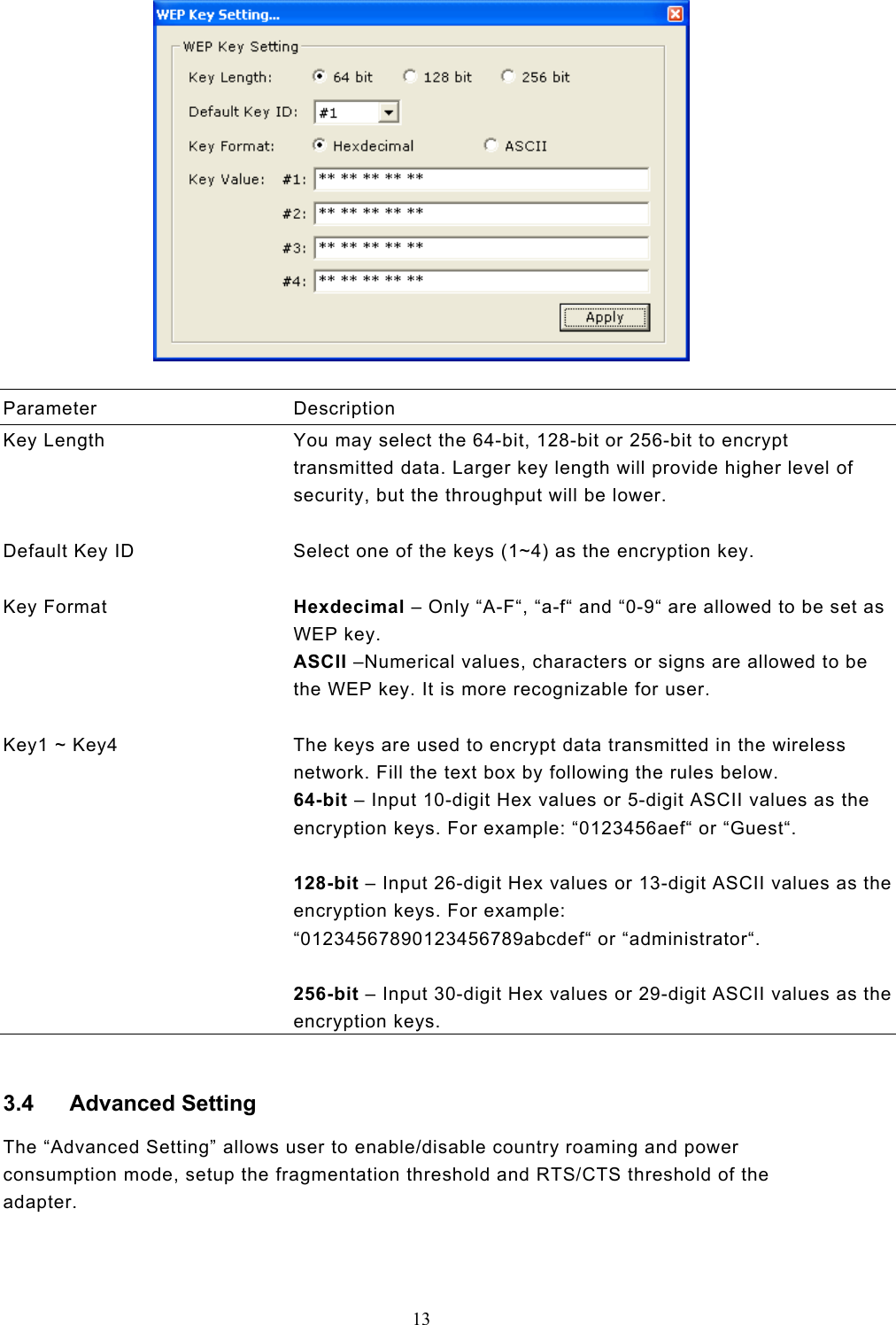
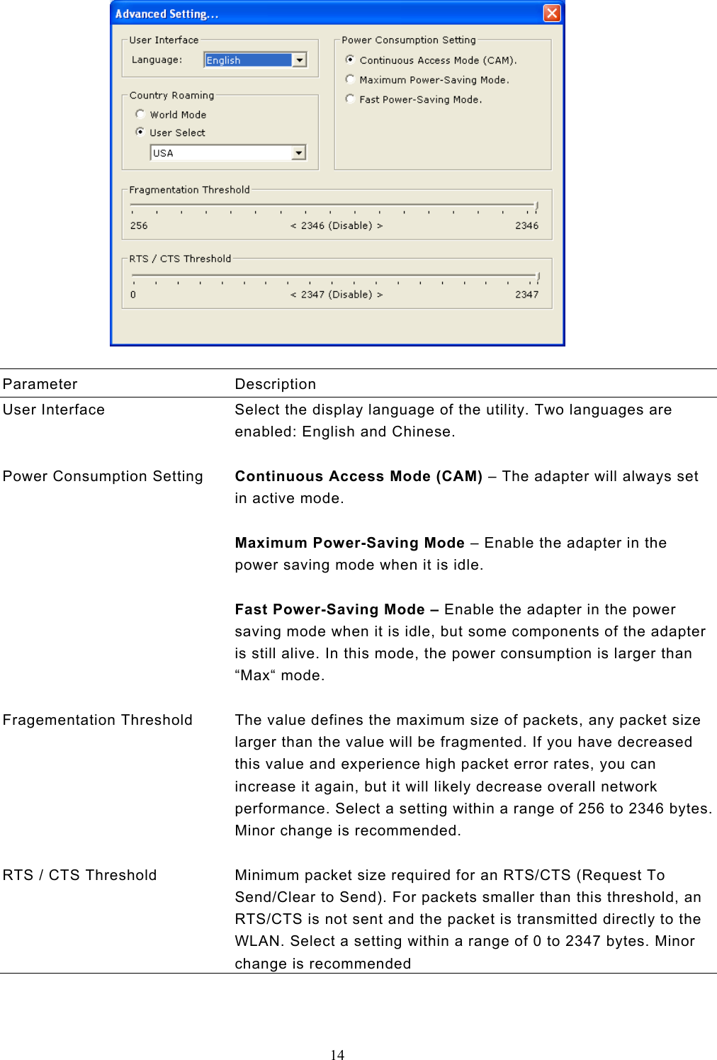
USERS MANUAL
Navigation menu
Upload a User Manual
Namespaces
Wiki Guide
HTML
PDF
Info
Views
User Manual
Discussion / Help
Navigation