Edimax Technology Co 9573250506 802.11g (Super G) Wireless LAN PCI Card User Manual
Edimax Technology Co Ltd 802.11g (Super G) Wireless LAN PCI Card
UserManual.wiki
>
Edimax Technology Co
>
9573250506 User Manual
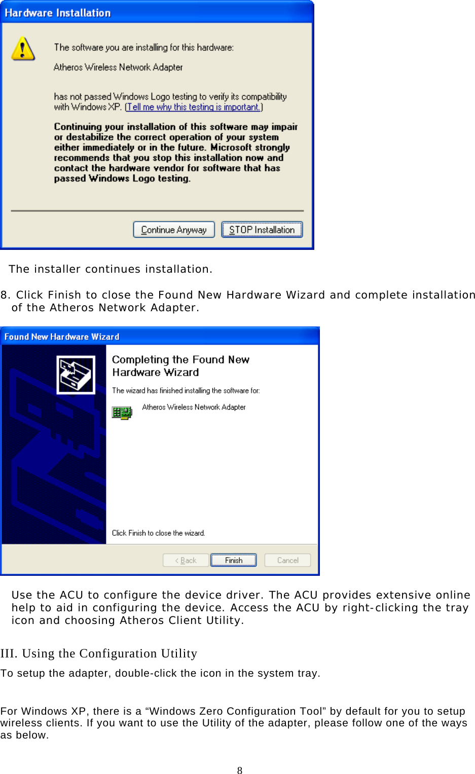
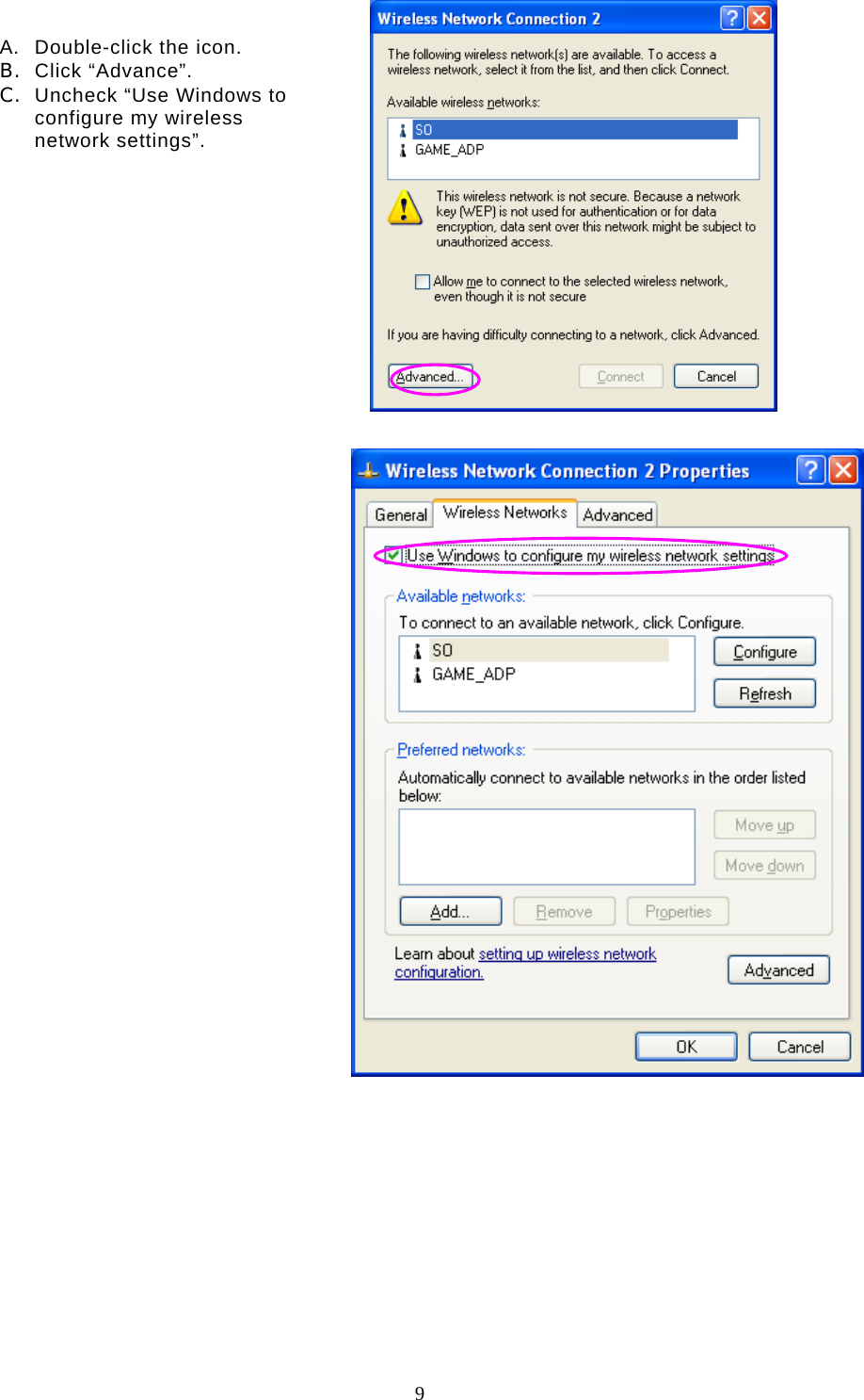
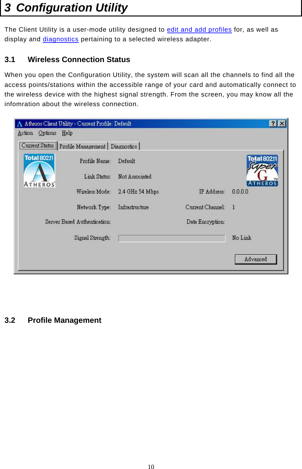
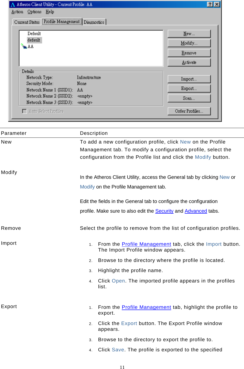
Users Manual
Navigation menu
Upload a User Manual
Namespaces
Wiki Guide
HTML
PDF
Info
Views
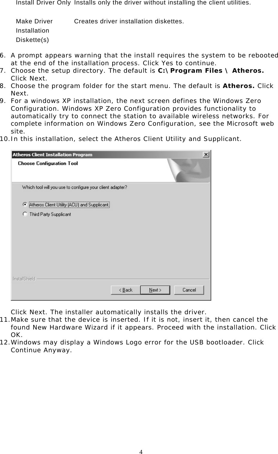
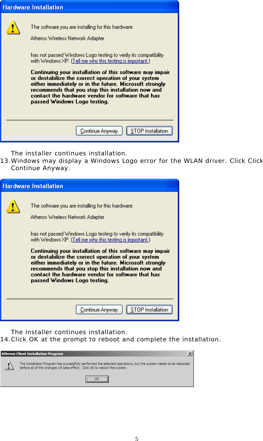
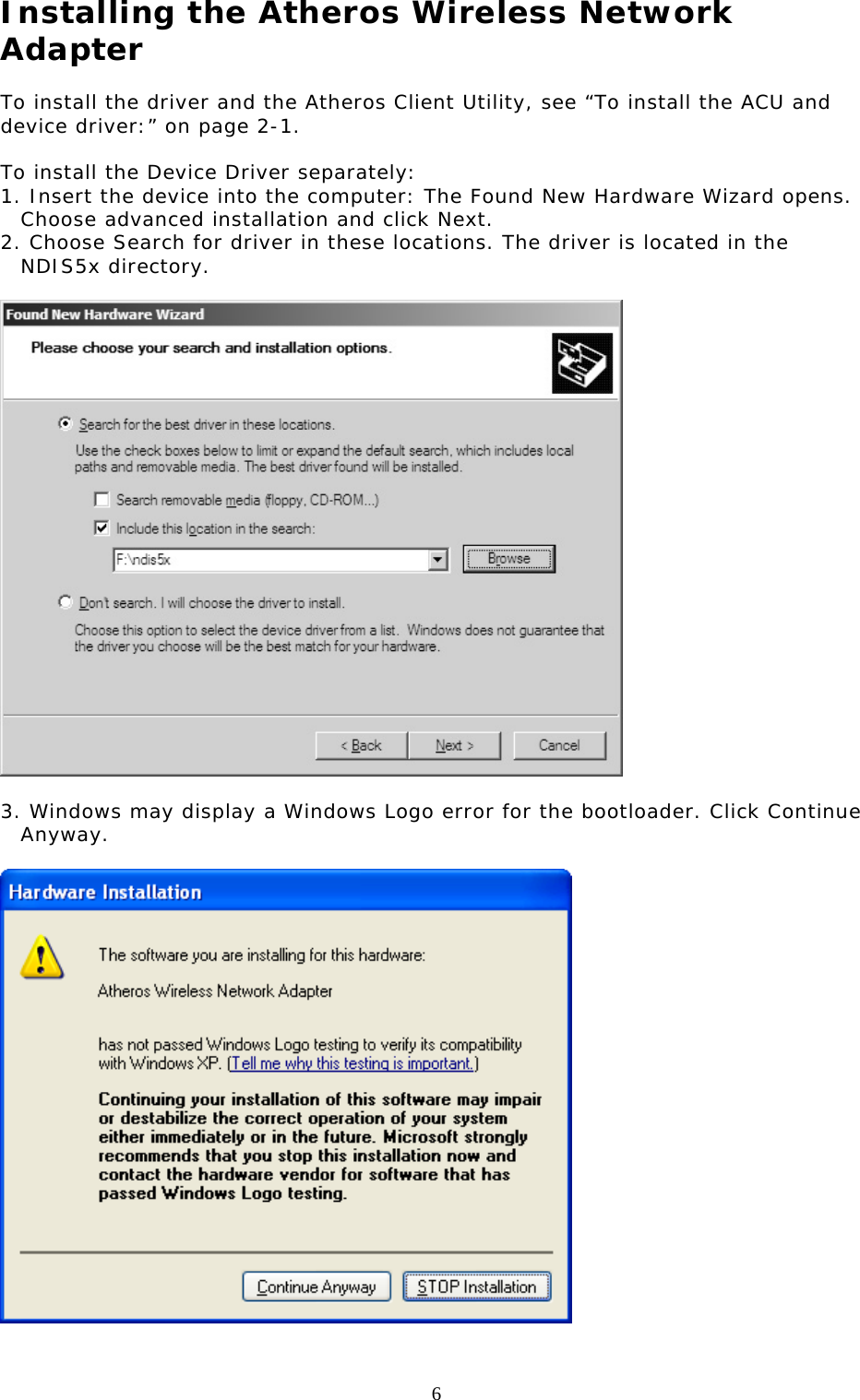
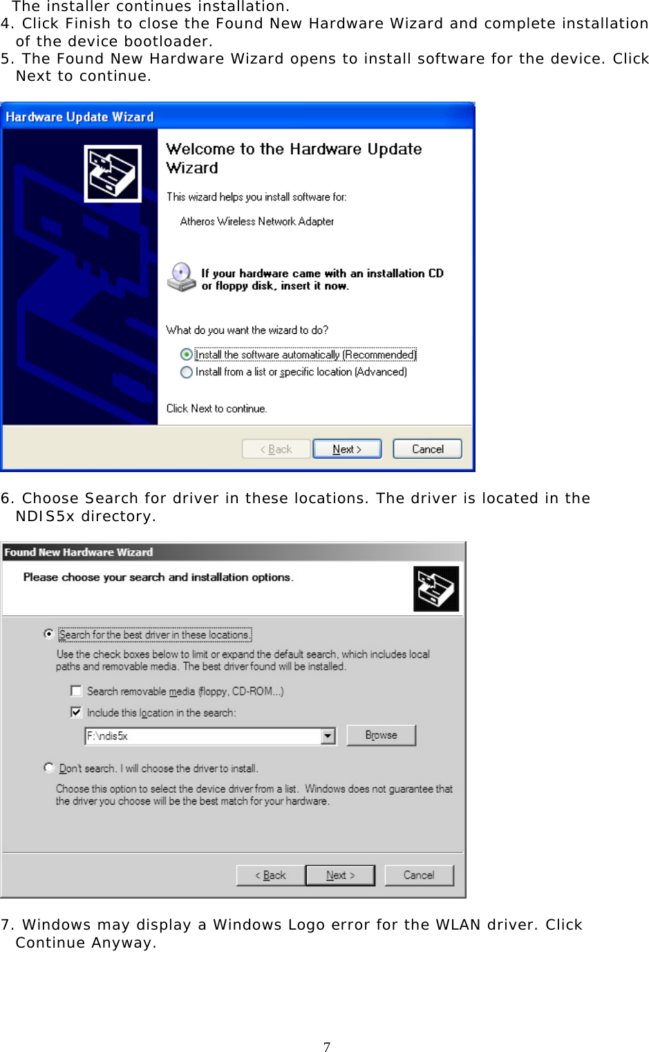
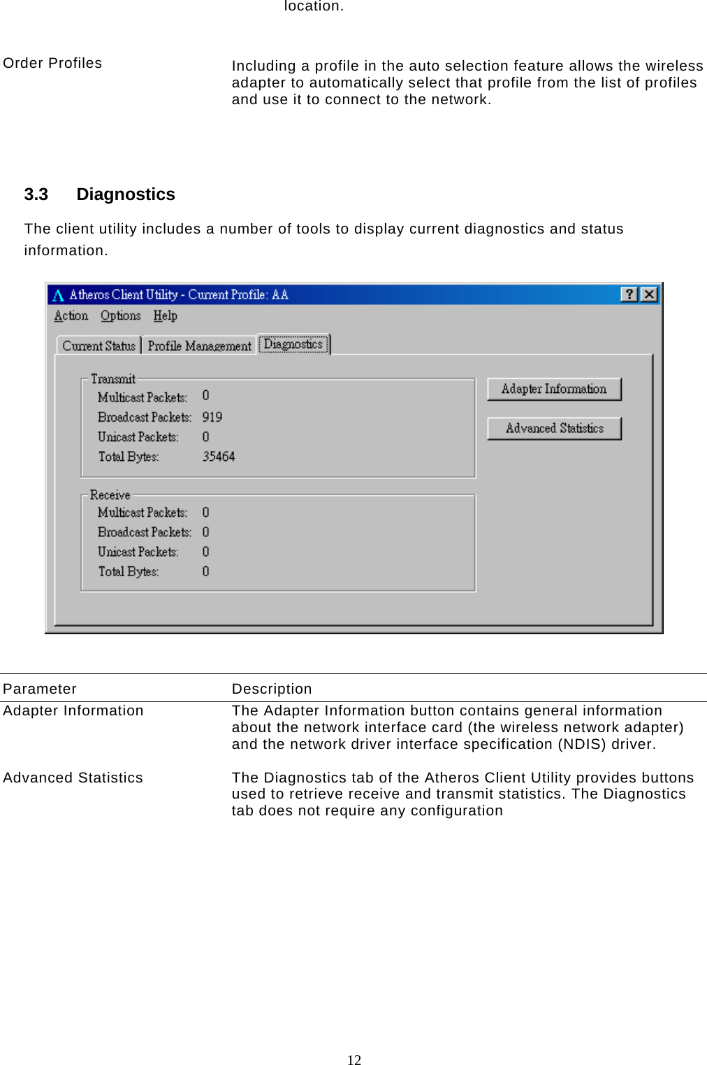
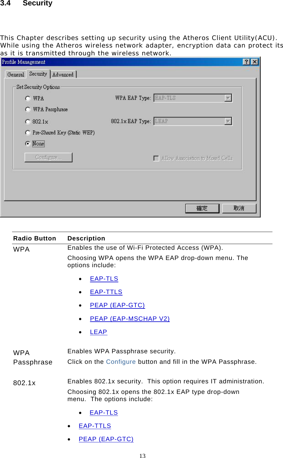
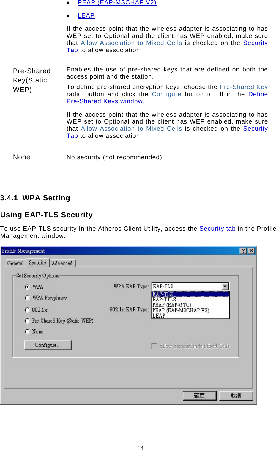
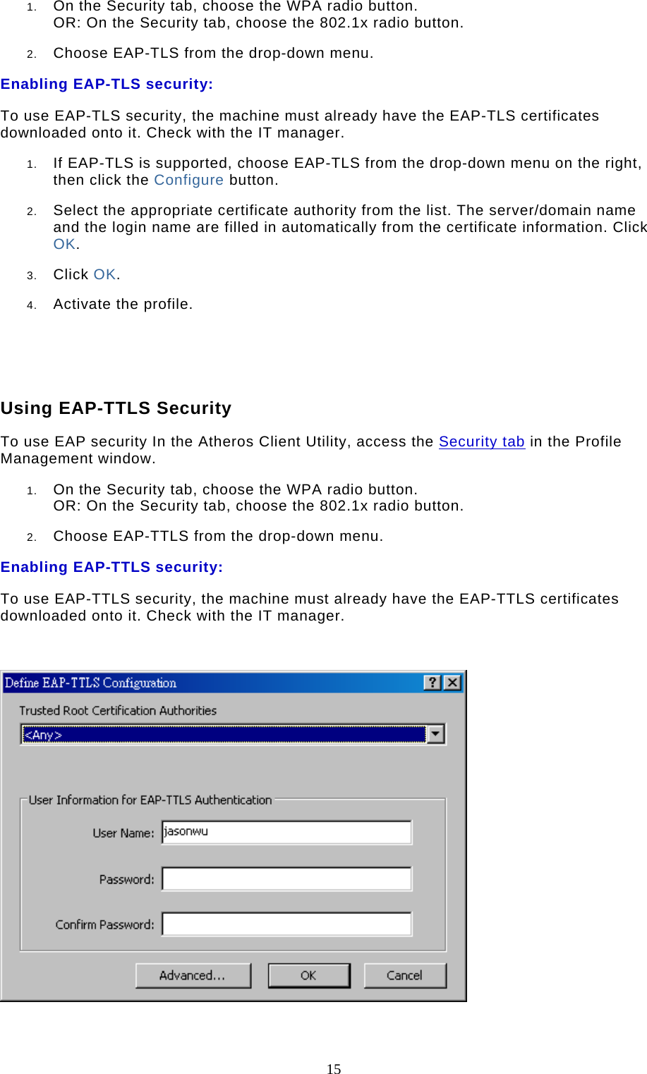
User Manual
Discussion / Help
Navigation