Edimax Technology Co C800AP1022 11n Wireless LAN Video Bridge User Manual
Edimax Technology Co Ltd 11n Wireless LAN Video Bridge
UserManual.wiki
>
Edimax Technology Co
>
C800AP1022 User Manual
User manual
Navigation menu
Upload a User Manual
Namespaces
Wiki Guide
HTML
PDF
Info
Views
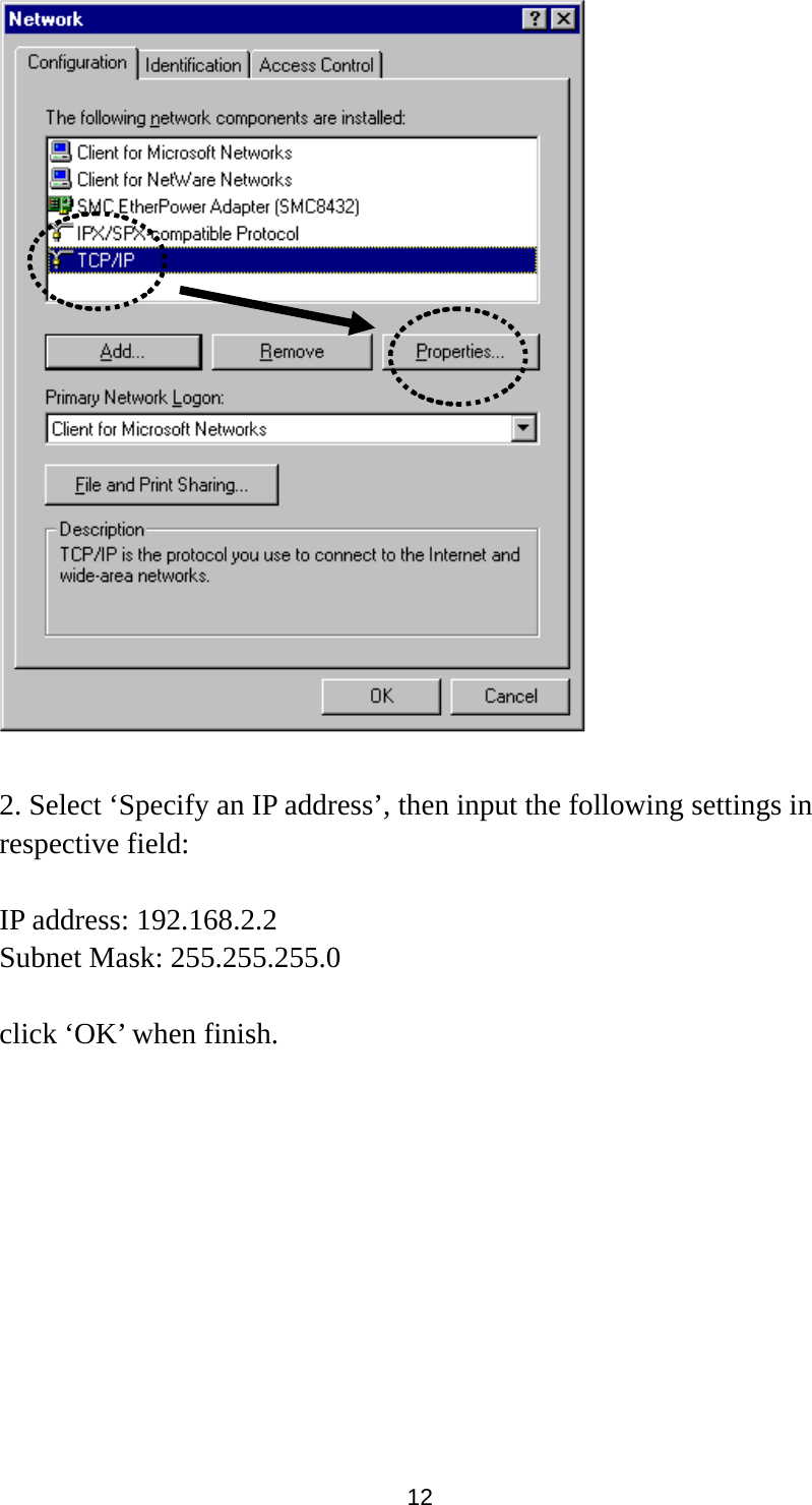
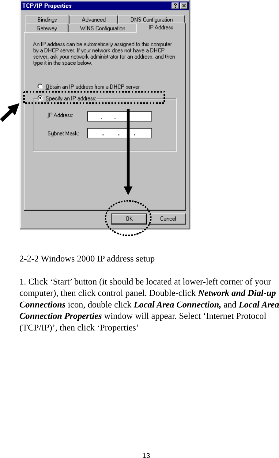
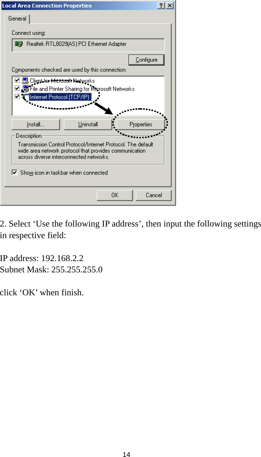
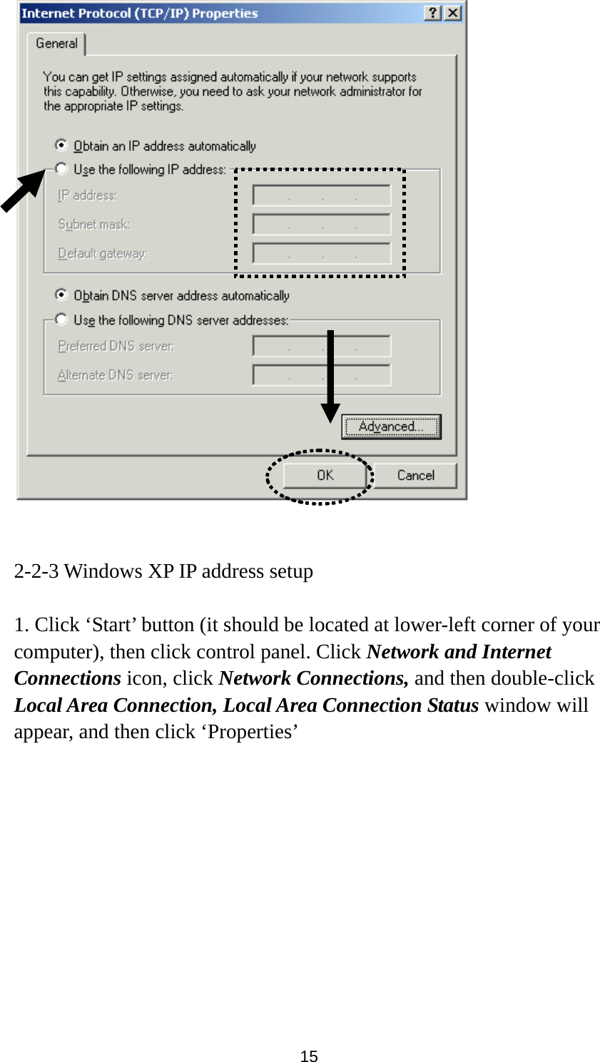
User Manual
Discussion / Help
Navigation