Edwards Lifesciences WPMS Wireless Physiologic Monitoring System User Manual 594081
Edwards Lifesciences LLC Wireless Physiologic Monitoring System 594081
Manual

1
Pressure Monitoring using the
Wireless Physiologic Monitoring
System And TruWave Disposable
Pressure Transducer
- DRAFT -
For Wireless Models:
WTP1000, WTMXXX
O
p
erato
r
’s Manual
2
Table of Contents
Introduction
General Safety
Warnings, Cautions and Notes
Intended Use
Indications for Use
Contraindications
Device Description
System Functional Description
System Components
Qualified Patient Monitors
Accessories
System Controls and Indicators
System Operation
System Receiving, Inspection and Assembly
System Programming and Set up
Programming Frequencies
System Set Up
Operation
Checking The Battery Level
Setting the Color Channel
Establishing the Link
Establishing Multiple Links On The Same Patient
Confirming the Link
Terminating the Link
Changing the Link
Maintenance
Transmitter Modules
Batteries
AC Adapter
IV Pole Holder Assemblies
Cleaning
Troubleshooting
System Fault Indicators
Symptoms and Remedies
Technical
Reorder and Model numbers
Specifications
Returned Goods Authorization
Technical Assistance
Warranty
3
Introduction
General Safety
This section provides information on the safe use of the Wireless Physiologic
Monitoring System with the TruWave Disposable Pressure Transducer. Read
and understand the information contained in this section before operating the
Wireless Physiologic Monitoring System with the TruWave Disposable Pressure
Transducer. Always follow the warnings, cautions and notes throughout this
document.
Warnings, Cautions and Notes
WARNINGS
When using the Wireless Physiologic Monitoring System with the TruWave
Disposable Pressure Transducer, appropriately qualified medical staff must
routinely monitor all patient vital signs and comply with the following;
● Patient monitor vital signs alarm limits must be set and active while using the
Wireless Physiologic Monitoring System with the TruWave Disposable Pressure
Transducer. Failure to activate alarms may cause delay or absence of
notification pressure signal loss.
● Performance of installation, operation or maintenance procedures other than
those described in this manual may create hazards and may cause the
manufacturer’s warranty to become void.
● Sterile components are designed for a single use only. If unauthorized
disposable components are used, proper operation cannot be guaranteed.
● Adherence to sterile technique must be observed when making all sterile
connections to the TruWave Wireless pressure transducer.
● Never operate damaged or wet equipment.
● Do not use this device in the presence of flammable anesthetic gases.
● The Wireless Physiologic Monitoring System should only be used on patient
monitors that have been validated for compatibility. Refer to Table 1 Qualified
Monitors list in this manual or contact the manufacturer for the most current list.
4
● The Wireless Physiologic Monitoring System should be inspected and tested
routinely prior to and during use.
● The Wireless Physiologic Monitoring System should not be used to provide
pressure triggered synchronization for intra aortic balloon pumps.
● The Wireless Physiologic Monitoring System is not Magnetic Resonance
Imaging compatible. Damage and/or injury to the patient or operator may result if
exposed to the MRI magnetic fields.
CAUTIONS
● Batteries should not be left in the devices for extended periods of time.
● Do not immerse or soak devices in any liquids.
● Do not steam, radiation or EO sterilize the electronic devices. Damage or
failure to operate may result.
● This device complies with part 15 of the FCC Rules. Operation is subject to
the following two conditions: (1) This device may not cause harmful interference,
and (2) this device must accept any interference received, including interference
that may cause undesired operation.
● The Wireless Physiologic Monitoring System has been tested for compliance of
US FCC CFR47 Part 95 H. Any modifications or tampering of the device may
cause failure of compliance.
● Operation of this equipment requires the prior coordination with a frequency
coordinator designated by the FCC for the Wireless Medical Telemetry Service.
NOTES
● This equipment has been tested and found to comply with the limits for a Class
B digital device, pursuant to part 15 of the FCC Rules. These limits are designed
to provide reasonable protection against harmful interference in a residential
installation. This equipment generates, uses and can radiate radio frequency
energy and if not installed and used in accordance with the instructions, may
cause harmful interference to radio communications. However, there is no
guarantee that interference will not occur in a particular installation. If this
equipment does cause harmful interference to radio or television reception, which
can be determined by turning the equipment off and on, the user is encouraged
to try to correct the interference by one or more of the following measures:
-Reorient or relocate the receiving antenna.
5
-Increase the separation between the equipment and receiver.
-Connect the equipment into an outlet on a circuit different from that to which the
receiver is connected.
-Consult the dealer or an experienced readio/TV technician for help.
● Other devices operating in the Wireless Medical Telemetry Service bands can
adversely affect the operation of the Wireless Physiologic Monitoring System.
● For best performance, allow device to equilibrate to room temperature.
6
Intended Use
INDICATIONS FOR USE
The Wireless Physiologic Monitoring System is indicated for use on patients
requiring physiologic monitoring. The Wireless Physiologic Monitoring System is
intended to perform wireless transmission of physiological patient information to
remote patient monitors using standard digital communication technologies and
protocols.
CONTRAINDICATIONS
The Wireless Physiologic Monitoring System is contraindicated for the following
clinical applications;
Invasive pressure wave trigger synchronization for intra aortic balloon
pump devices. This is contraindicated due to timing sensitivities.
Device Description
SYSTEM FUNCTIONAL DESCRIPTION
The Wireless Physiologic Monitoring System is a wireless device designed to be
used in place of a standard cable. The system communication operates using
frequency bands designated for use by the Wireless Medical Telemetry Service.
The system RFID link process operates using the 134.2 KHz frequency band and
is compliant per US FCC CFR47 Part 15.
The Wireless Physiologic Monitoring System is comprised of two components.
Transducer Module (X Unit, Model WTP1000) – This component
provides the excitation voltage to the transducer and transmits the
transducer signal via radiofrequency to the M unit.
Monitor Module (M Unit, Model WTM XXX – See Table 1) – This
component connects to the patient monitor ( via the Invasive Blood
Pressure (IBP) connection in the case of pressure monitoring) and
receives the radiofrequency data transmission from the X unit Transducer
module. The data is then displayed on the patient’s bedside monitor.
Each M Unit comes with a connector specific to the monitor it has been
designed for. See Table 1 for applications and model numbers.
The Transducer modules (X Units) are battery powered and also provide the
excitation voltage to the pressure transducer. The Monitor modules (M Units)

7
obtain their operating power from the bedside monitor. Some exceptions exist
that require a supplemental power source for the Monitor modules.
To use the Wireless Physiologic Monitoring System for pressure monitoring, a
Transducer module is connected to a TruWave disposable pressure transducer
and a Monitor module is connected to a patient monitor pressure signal input.
The system uses radiofrequency transmission to communicate pressure data
from the transducer to the monitor in place of the cable.
The Transducer modules are typically mounted to an IV pole or on the patient.
The Monitor modules are plugged into the monitor input connectors and hang
from the monitor.
TABLE 1 – QUALIFIED PATIENT MONITORS
Monitor Manufacturer Monitor Model M Unit Model
GE Dash 4000 WTM 507
MDE Escort 2 WTM 021
Philips/HP Omnicare/M1006B Module WTM 083
Spacelabs Ultraview 90367 WTM019
8
ACCESSORIES
The Wireless Physiologic Monitoring System for pressure monitoring is used in
conjunction with the following accessories.
IV Pole Holder (Model WDTH1)– A holder assembly is provided for
mounting the Transducer Modules conveniently to an IV pole.
AC Adapter (Model WAC1)- An AC power supply is provided for those
Monitor modules that cannot obtain adequate power from the monitor.
Battery Pack (Model W9VBP1)– A 9 volt battery pack is provided for
those Monitor modules that are used with Transport monitors that do not
supply adequate operating power.
FastLink (Model WLINK1) – A passive RFID transponder card with
unique serial number is used as a unique identifier for the operator to link
pairs of modules.
Frequency Programming Card (Model WDATA1) – A passive RFID
transponder card with programmed frequency data is used to program the
operating frequencies of the Transducer and Monitor Modules.
Wireless Patient Mount (Model WDTPM1)- A holder assembly is
provided for mounting the Transducer Module to the patient, adjacent to
the pressure transducer.
9
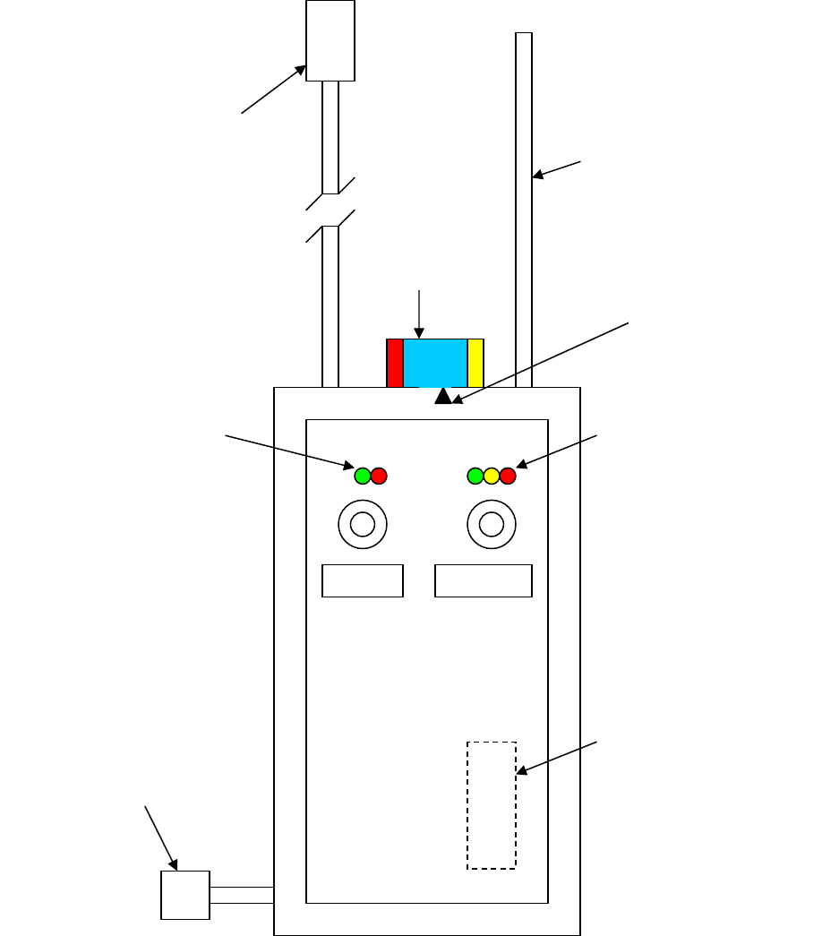
SYSTEM CONTROLS AND INDICATORS
The controls and indicators for the Transducer module and the Monitor module
are similar. Differences are noted in the figure.
DC input
connector for AC
Adapter – Monitor
Module (M Unit)
only
LINK
TEST
Transducer
(X unit) or
Monitor
(M unit)
Connecto
r
Antenna
Color
Knob
Battery
Level
System
Indicators
2
RFID
Reader
(Inside)
Color arrow
indicator located
on back side

10
SYSTEM CONTROLS AND INDICATORS
FUNCTIONAL DESCRIPTIONS
CONTROLS
A simple method of linking the appropriate X unit (example; Arterial blood
pressure transducer) to the appropriate M unit (example: Monitors’ Arterial blood
pressure channel) must occur before the TruWave transducer can be zeroed and
physiologic data is displayed on the bedside monitor.
LINK (On/Off) Button – Pressing the LINK button for ½ second, initiates the
pairing process between the Transducer Module (X Unit) and the Monitor Module
(M Unit) by activating the RFID reader system. The linking process can be
initiated from either the X Unit or the M Unit.
The LINK button also serves to terminate an existing communication link.
Pressing and holding the LINK button for two seconds, while already linked, will
terminate the link. Pressing the Link button again will initiate a new link process.
If no RFID user card is presented, the Module will time out (approximately 10
seconds) and turn off.
TEST Button – Pressing the TEST button sends a test signal (approximately
100 mmHg) from the Module to the monitor display for purposes of testing and
verifying proper module and link performance. The test signal is sent as long as
the TEST button is held. If the M Unit TEST button is used, the test pulse is
generated from the M Unit and the function and connection of the M unit is
verified. If the X Unit TEST button is used, the test pulse is generated from the X
Unit and the link performance is verified.
Pressing the TEST button on the X Unit will also indicate the battery level.
Pressing the TEST button on the M Unit will only indicate battery level if the M
Unit is battery powered. It does not indicate the battery level of the X Unit that it
is linked to.
Note: The battery in the X Unit should always be replaced with a new one when
setting up a new pressure transducer line. A new AA Alkaline battery will
typically provide 40 hours of continuous operation.
Color Channel Knob – A rotating selector knob provides 5 color channels. The
channel colors (also with #’s) are Red (1), Blue (2), Yellow (3), Green (4) and
White (5). The color channel selection is indicated by the arrow on the rear
panel.
The color channel selector is used to aide the operator in organizing pressure
signals on how they appear on the patient monitor. These color settings also
provide channel information between X and M units. The color RED is typically

11
selected for an arterial pressure. The M Unit plugged into the monitor where
arterial pressure is displayed would be set to RED on the color knob. The X Unit
connected to the patient’s arterial line would then also be set to RED. (Blue:
CVP/RAP, Yellow: Pulmonary Artery Pressures, Green/White: Misc. physiologic
pressures)
Another benefit of the color channel is ease of patient set up. Using different
colors for different pressure signals on the same patient allows the operator to
simultaneously LINK all X Units to their respective M units. See LINK
instructions.
RFID Reader (Inside housing) – The Wireless Physiologic Monitoring System for
pressure monitoring has a RFID (Radio Frequency Identification) reader
incorporated into each X and M unit. The FastLink Cards provided with the
system are each encoded with a unique identification number so that none are
the same. The FastLink card provides the unique ID code that will be read by
each X unit and M unit and will be used by the modules to identify each other.
INDICATORS
System Indicator LED’s – Green LED indicates linking status. Red LED
indicates system fault conditions.
Battery Level LED’s – Green indicates full battery level. Yellow indicates
medium power level. Red LED indicates low power and replacement required.
The Red LED will automatically begin blinking when there is approximately 4
hours or less of battery power remaining.
Audible beeper (not shown) – The X Unit will automatically begin emitting an
audible signal (approximately once every 5 seconds) when there is
approximately 4 hours or less of battery power remaining.
The beeper signals the corresponding color channel number selected during
linking.
12
System Operation
System Receiving, Inspection and Assembly
The components of the Wireless Physiologic Monitoring System are shipped
separately. Each package should be carefully inspected for shipping damage. If
damage is detected, file a damage claim with the carrier.
Each transmitter module should be carefully unpacked and inspected. These
modules are electronic devices and should be handled accordingly.
The Wireless Physiologic Monitoring System Modules (X and M units) are fully
assembled and are ready for use. The IV holder assembly is comprised of a
Module holder and a Backplate holder.
System Programming and Set Up
The Wireless Physiologic Monitoring System operates in the frequency bands
designated for use by the Wireless Medical Telemetry Service. The devices
require registration and deployment by an authorized frequency coordinator.
ASHE (American Society for Healthcare Engineering) has been designated by
the FCC (Federal Communications Commission) to manage the WMTS
frequencies.
The factory default settings for the operating frequency bands are as follows;
1395 – 1400 MHz
1427 – 1429.5 MHz
Devices can be reprogrammed to operate in portions of these bands if required
by the frequency coordinator. Programming RFID cards may be obtained from
Edwards Lifesciences if reprogramming of the frequencies is required.
PROGRAMMING FREQUENCIES
The Wireless Physiologic Monitoring System is reprogrammed as follows.
1. Verify that a battery is installed in the X Unit or that the M Unit is
connected to a monitor that has been powered.
2. Verify that the proper Frequency Programming Card (FPC) has been
selected by checking the Frequency information printed on the card.
3. Momentarily press the LINK button on the Module to be reprogrammed.
The system indicator LED will begin blinking green once per second. This
indicates that the reader is active and ready.
4. Hold the FPC against the lower portion of the module housing.
5. When the Module system indicator LED blinks green quickly (3 times per
second), the module has been programmed.
13
6. If the system indicator LED blinks red (2 times per second), the
programming has failed and needs to be retried.
7. Test each module for linking to verify proper frequency programming.
SYSTEM SET UP
The Wireless Physiologic Monitoring System for pressure monitoring is set up as
follows;
1. Clamp the Transducer Module Holder bracket to the desired IV Pole.
2. Clamp the Transducer Backplate bracket to the IV Pole, a few inches
below Module bracket. This will later be adjusted to the patient height per
TruWave instructions.
3. Remove the battery compartment cover from the Transducer Module.
4. Install an Alkaline AA size battery into the battery compartment noting the
polarity for positive and negative terminals.
NOTE: The unit will not operate if the battery has been installed incorrectly.
5. Replace battery compartment cover.
6. Mount Transducer module onto Holder by firmly pressing the hook and
loop fastening system together.
7. Plug the Monitor Module into the patient monitor pressure input connector.
Note that position of input connector will determine position of trace on the
monitor display.
CAUTION: The link performance range is designed to operate up to 15 feet in
unobstructed space. Obstacles in between modules may cause some signal
interference and should be avoided.
8. Using standard disposable transducer set up procedures, set up and
prime a TruWave pressure transducer and install in Holder Backplate.
9. Plug the transducer connector into the Transducer Module connector.
10. Repeat steps 3 through 9 for additional pressure lines.
Set up is complete.
SYSTEM SET UP USING PATIENT MOUNT (WDTPM1)
The Wireless Physiologic Monitoring System for pressure monitoring is set up as
follows using the patient arm band accessory;
1. Remove the battery compartment cover from the Transducer Module.
2. Install an Alkaline AA size battery into the battery compartment noting the
polarity for positive and negative terminals.
NOTE: The unit will not operate if the battery has been installed incorrectly.
3. Replace battery compartment cover.
4. Open the internal fabric flap on the Patient Mount arm band.
5. Place the Transducer Module into the pocket by feeding the antenna,
cable and color knob through the access hole. The control panel should
face the clear window.
14
6. Place the Patient Mount arm band on the patients upper arm on the same
arm that the transducer has been mounted.
7. Use the adjustable fastening belt to secure the Patient Mount.
WARNING: Do not overtighten the patient mount to prevent discomfort, injury
or compromise blood circulation.
8. Plug the transducer cable into the transducer module connector.
WARNING: Remove bedding, gown, pillow from the immediate area of the
Patient Mount and the transducer module. Covering of the module may
impair the ability to visualize and hear the system indicators and low battery
alert.
CAUTION: The link performance range is designed to operate up to 15 feet in
unobstructed space. Obstacles in between modules may cause some signal
interference and should be avoided.
Set up is complete.
SYSTEM SET UP USING BATTERY PACK (W9VBP1)
The Wireless Physiologic Monitoring System for pressure monitoring is set up as
follows using the battery pack accessory;
1. For instances where a Monitor Module is being used with a bedside or
transport monitor that requires supplemental power, the Battery Pack
accessory can be used. This can be determined when the Monitor
Module fails to power on when the patient monitor is turned on.
2. Remove the battery cover on the Battery Pack housing.
3. Install a new 9 Volt Alkaline battery.
4. Plug the Battery Pack connector into the Monitor Module power adaptor
connector.
Set up is complete.
Note: The Battery Pack accessory should be unplugged from the Monitor Module
when not in use to prevent battery drainage.
15
Operation
CHECKING THE BATTERY LEVEL
1. Press and hold the TEST button on the X unit (or M Unit if battery
powered) to activate the Battery level LED indicators.
2. The Battery level LED’s will illuminate as follows;
Green – indicates good charge
Yellow – indicates medium charge
Red – indicates low charge and battery change required.
WARNING: Do not begin use if a low battery condition is detected.
Replace with a new battery even if the alert has not begun flashing or
beeping.
CAUTION: Replace the module if a battery check is performed and no
LED lights up. One of three conditions should be lighted or a LED has
failed.
Note: The Battery level LED indicators on the M unit are not active if it is
not battery powered. Pressing the M unit TEST button will then activate
the pressure test signal function only.
SETTING THE COLOR CHANNEL
1. Verify that the X and M unit to be paired have been set to the same color
channel. Rotate the Color knob to the desired color indicated by the arrow
on the rear panel.
Caution: If paired X and M units are not set to the same color, they cannot
be LINKED.
2. If more than one pressure line is being used on the same patient, X and M
pairs should be set to different colors to minimize confusion.
WARNING: Do not attempt to link multiple units with the same color wheel
setting, with the same FastLink card, at the same time. It is possible that the
signals may be crossed.
Note: Once the link has been established, turning the color wheel will not
disrupt the link.
CAUTION: Do not turn the color wheel once the pressure link to avoid
confusion of paired modules that may indicate different colors.
16
ESTABLISHING THE LINK
Verify that the system set up has been completed and that a FastLink Card is
available.
Note: The link may be initiated from either the X or M unit. For instructional
purposes, this example will be started from the X unit.
1. Press and hold the LINK button of the X unit for at least ½ second. The
system green LED will begin blinking indicating that the RFID reader is
ready.
2. Position the FastLink card against the lower portion of the X Unit
housing. The system green LED will change to a quick blink and an
audible beep will sound indicating that the FastLink card is being read.
CAUTION: The Fastlink card being held against the module in a position
other than the recommended lower portion may result in the FastLink card not
being properly read even if an audible beep is heard.
3. Press the LINK button of the desired M unit. The system green LED will
begin blinking indicating that the RFID reader is ready.
4. Position the FastLink card against the lower portion of the M Unit housing.
The system green LED will change to a quick blink and an audible beep
will be heard indicating that the FastLink card is being read.
CAUTION: The Fastlink card being held against the module in a position
other than the recommended lower portion may result in the FastLink card not
being properly read even if an audible beep is heard.
Once the X and M units have successfully identified each other, a confirming
audible beep corresponding to the color channel number will be heard from
each unit and the green LED will light constant for a few seconds. The
pressure trace will be displayed. The system green LED will then slowly
blink, continuously.
Note: Monitors will require that the zero procedure be completed prior to any
pressure trace being displayed.
17
ESTABLISHING MULTIPLE LINKS ON THE SAME PATIENT
Verify that the system set up steps have been completed and that a FastLink
Card is available.
Note: The link may be initiated from either the X or M unit. For instructional
purposes, this example will be started from the X unit.
1. Select different color channels for each pair of X and M units for the
patient. The center of the color band should be aligned with the color
indicator arrow located on the rear panel.
2. Press the LINK button of each X unit. The system green LEDs will begin
blinking indicating that the RFID readers are ready.
3. Position the FastLink card against the lower portion of the first X Unit
housing. When the system green LED changes to a quick blink indicating
that the FastLink card has been read, move to the next X unit. Repeat
until all X units have read the FastLink. The X module allows
approximately 10 seconds from pressing the LINK button to reading the
FastLink card.
4. Press the LINK button of each M unit. The system green LEDs will begin
blinking indicating that the RFID readers are ready.
5. Position the FastLink card against the lower portion of the first M Unit
housing. When the system green LED changes to a quick blink indicating
that the FastLink card has been read, move to the next M unit. Repeat
until all M units have read the FastLink. The M module allows
approximately 10 seconds from pressing the LINK button to reading the
FastLink card.
Once the X and M units have successfully identified each other, a confirming
audible beep corresponding to the color channel number will be heard from
each unit. The pressure trace will be displayed. The system green LED will
slowly blink, continuously.
Note: Once a X or M module has read the FastLink card, the user has
approximately 30 seconds to execute the link steps or the unit will time out
and entire linking sequence must be repeated.
Note: Some monitors may require that the zero procedure be completed prior
to the pressure trace being displayed.
18
CONFIRMING THE LINK
Note: There are three locations that the Wireless System can be tested or
diagnosed from, the M unit, the X unit and the pressure transducer.
1. Press the TEST button on the M unit to send a test signal (approximately
100 mmHg) to the monitor. This verifies proper connection to the monitor
and M unit function.
2. Press the TEST button on the X unit to send a test signal (approximately
100 mmHg) to the monitor. This verifies proper X unit function and link
performance.
3. If clinically indicated, pull the Snap-Tap flush device on the TruWave
transducer to send a pressure pulse to the monitor. This verifies proper
transducer connection and function.
TERMINATING THE LINK
1. Press the LINK button for at least 2 seconds, release and wait
approximately 10 seconds. The unit will terminate the existing link
communication and turn itself off.
CHANGING THE LINK
1. Press the LINK button for two seconds to terminate the existing link.
Press the LINK button for at least ½ second and the RFID reader will be
turned on
2. Follow instructions above for “Establishing the Link”.
TRANSPORT LINKS
To prevent interference between a transported patient who is entering an area of
other patients who are already linked, it is recommended that the transport
patient links be terminated prior to entering the area. Once the patient is in the
area, the link may be relinked without interfering with other links.
19
Maintenance
Transmitter Modules
The Wireless Physiologic Monitoring System modules should always be cleaned
and inspected after each use.
Batteries
The Wireless Physiologic Monitoring System uses size AA Alkaline batteries. A
new battery should always be used when starting a procedure. There are no
federal regulations governing the handling and disposal of these batteries.
Batteries should not be left in the Transducer Module for extended periods of
time. Disposal of batteries should coincide with the disposal of the pressure
transducer.
See hospital, state or local regulations for disposal or recycling instructions.
AC Adapter
The Wireless Physiologic Monitoring System Monitor Module requires power
obtained from the patient monitor pressure module to operate. Some monitor
models do not provide adequate levels of power. For these cases, an AC
Adapter can be used.
These power supply adapters can be installed and secured to the hospital
monitor mounting bracket system. They do not require maintenance. Use only
the hospital grade power cord supplied with the adaptor.
IV Pole Holder Assemblies
The Wireless Physiologic Monitoring System Holders should always be cleaned
and inspected after each use.

20
Cleaning
The Wireless Physiologic Monitoring System is comprised of several
components. Cleaning instructions for those components are listed here.
WARNING: Unplug the AC Adapter from its wall power source prior to any
cleaning. Disconnect all modules from patient monitors and remove all
batteries prior to any cleaning.
Caution: Use only approved cleaning agents and solutions.
Transducer Module/Monitor Module/AC Adapter/Holders
Apply cleaning solution to moistened towel to clean unit. Do not immerse. Wipe
off any excess solution immediately.
Component Approved cleaning agents
Transducer Module
Monitor Module
IV Pole Holders
Isopropyl Alcohol
FastLink card
Warm soapy water
AC Adapter
Warm soapy water
TruWave transducer
Not Applicable – disposable single use unit

21
Troubleshooting
System Fault Indicators
The following conditions will be reflected by the system indicators.
CONDITION INDICATOR RESPONSE
Incorrect FastLink read
Simultaneous pairs with
same color channel
System Red LED
2 blinks per second
System malfunction requiring
service
System Red LED
Continuous on
Network full
Excess interference
System Red LED
1 blink per second
Battery Low
Test Red LED
Beeper
1 blink per second
Beep once per 5 seconds
Lost link
System failure
Monitor trace Negative 100 mmHg signal
Symptoms and Remedies
Should the listed Corrective Action fail to remedy the condition, the unit should
not be used.
SYMPTOM PROBABLE CAUSE CORRECTIVE ACTION
No power
Replace battery
Battery installed
backwards
Replace battery
X Unit does not respond
Battery voltage below
start up threshold
Replace battery
No power
Verify Monitor power is
turned on
M Unit does not respond
Insufficient power Verify if AC adapter is
plugged in
Conflicting color
channels; color wheel not
in switch detent position
Verify that the paired X and
M units are set to the same
color channel
More than one pair of X
and M units are set to
same channel
Verify that different paired X
and M units are set to
different color channels
X and M Units will not link
Local Network is full,
excessive interference
present
Move X unit location around
patient
Convert to cable usage

22
FastLink card has not
been properly read
Redo Link procedure placing
the FastLink card adjacent to
the lower potion of the
module
X Unit battery is dead
Verify battery level
M Unit is unplugged Verify M connection is good
to monitor input
Monitor trace is gone
System malfunction
Confirm M and X function
with TEST button to isolate

23
Technical
Reorder Information
ITEM DESCRIPTION MODEL #
Transducer Module (X Unit)
Monitor Module (M Unit)
GE/Marquette
Philips
Spacelabs
MDE
IV Holder – Modules
IV Holder – Backplate
FastLink Card
Frequency Programming Card
AC Adapter
Monitor Module 9V Battery Pack
Wireless Patient Mount
WTP1000
WTM 507
WTM 083
WTM 019
WTM 021
WDTH1
WLINK1
WDATA1
WAC1
W9VBP1
WDTPM1
Specifications
PARAMETER SPECIFICATION
Environmental
Operating
15 deg C to 35 deg C
Physical
Dimensions (X&M units)
Weight
Fluid protection
1.5” W x 6.0”H x 1.5”D
3.8 cm W x 15.2 H x 3.8 D
6 oz. (170 gm)
IEC 60529 level IPX1

24
Electrical
Power Input
Transducer module:
Monitor module:
AC Adapter:
Safety
Electromagnetic Immunity
Electromagnetic Emissions
1.5 VDC – single AA Alkaline battery, 2500
mAh, (Duracell MX1500)
3.0 VDC, 25 mA
100-240 VAC 47-63 Hz Input
9.0 VDC, 1.1 A Output
EN60601-1
EN60601-1-2, IEC 61000-4
EN60601-1-2, CISPR 11, IEC 61000-3
Radiofrequency
RFID Reader System
Operating Frequency
Data Link Operating
Frequencies
Frequency channels (6 ea)
Channel bandwidth
Power output level
Range
US FCC CFR47 Part 15.209 Compliant
134.2 kHz
WMTS Bands
1395 MHz- 1400 MHz, 1427 MHz- 1429.5 MHz
US FCC CFR 47 Part 95 Subpart H Compliant
FCC has designated ASHE (American Society
for Healthcare Engineering) to manage the
WMTS (Wireless Medical Telemetry Service)
frequencies
1 1395.625 MHz
2 1396.875
3 1398.125
4 1399.375
5 1427.625
6 1428.875
600 kHz
-5 dBm
15 feet, 4.6 m in free space
FCC ID
Transducer/Monitor Module
FCC ID: S8HWPMS

25
System Performance
Network link capacity
X Unit battery life
Pressure Range
Accuracy
Frequency Response
Data Latency
Input impedance (M unit)
Output impedance (M unit)
Low battery warning
9 links
40 hrs typ.
-75 to 325 mmHg
+/- 4 mmHg or 4% of reading whichever is
greater
No less than 3 dB up to 10 Hz
≤ 60 msec
200-400 ohms
300 ohms +/- 5%
≤ 4 hours
Returned Goods Authorization
When returning a Wireless Physiologic Monitoring System module or accessory,
please pack the unit carefully in its original shipping container or another similarly
protective container. In the United States, call Edwards toll-free Technical
Support telephone number 800.822.9837 and obtain a Returned Goods
Authorization number and further instructions.
Technical Assistance
For technical assistance, please call Edwards Technical Support at the following
telephone numbers:
Inside the U.S. and Canada
(24 hours) 800.822.9837
Outside the U.S. and Canada
(24 hours) 949.250.2222
26
Warranty
Edwards warrants that the Wireless Physiologic Monitoring System is fit for the
purposes and indications described in the labeling for a period of one year after
the date of purchase when used in accordance with the directions for use.
Unless the equipment is used in accordance with such instructions, this warranty
is void and of no effect. No other express or implied warranty exists, including
any warranty of merchantability or fitness for a particular purpose. This warranty
does not include cables, tubing sets, or batteries used with this Wireless
Physiologic Monitoring System. Edwards’ sole obligation and purchaser’s
exclusive remedy for breach of any warranty shall be limited to repair or
replacement of the Wireless Physiologic Monitoring System at Edwards’ option.
Edwards shall not be liable for proximate, incidental, or consequential damages.
Caution: Federal (USA) law restricts this device to sale by or on the order of a
physician.
Because of continuing product improvements, prices, specifications, and model
availability are subject to change without notice.
27
U.S. Patents Pending
Trademarks
Edwards Lifesciences, stylized E logo, Edwards and TruWave are trademarks of
Edwards Lifesciences and TruWave are registered in the U.S. Patent and
Trademark Office.
DRAFT 9/14/05
Document 195501001 A
©Copyright 2005 Edwards Lifesciences, LLC
All rights reserved.
Edwards Lifesciences LLC Telephone 949.250.2500
One Edwards Way 800.424.3278
Irvine, CA 92614-5686 Fax 949.250.2525
Made in U.S.A. www.edwards.com