Efjohnson Smartzone 7780 Users Manual Book.bk
EFJohnson Radio FM Portable Radio Intrinsically-Safe SMARTNET, SmartZone Conventional 001-7780-500_7780Series_ServiceManual
7780 to the manual 5ce12480-cf06-491b-8427-3eef45a21ab8
2015-02-02
: Efjohnson Efjohnson-Smartzone-7780-Users-Manual-426517 efjohnson-smartzone-7780-users-manual-426517 efjohnson pdf
Open the PDF directly: View PDF ![]() .
.
Page Count: 116 [warning: Documents this large are best viewed by clicking the View PDF Link!]
First Printing
November 1999
778x (800 MHz)
SMARTNET™/SmartZone®/Conventional
7.5VDC,1and3Watts
806-824 MHz Transmit
851-870 MHz Receive
Part No. 242-778x-50x
Full Keypad (15-Key) Model Limited Keypad (3-Key) Model
SMARTNET™/SMARTZONE® PORTABLE
Series
7780
PRELIMINARY SERVICE
MANUAL

7780-SERIES
SMARTNET /SMARTZONE /CONVENTIONAL
FM TWO-WAY
PORTABLE RADIO
7.5 VDC
806-824 MHz Transmit, 851-870 MHz Receive
1-Watt (Low Power), 3-Watts (High Power)
Part No. 242-778x-50x
Copyright ©1999 by the E.F. Johnson Company
E.F. Johnson Company, which was founded in 1923, designs, manufactures, and markets
radio communication products, systems, and services worldwide. E.F. Johnson produces
equipment for land mobile radio and mobiletelephone services which include business,
industrial, government, public safety, and personal users.
Viking Head/EFJohnson logo, Call Guard®, PCTrunk™, and PCTune™ are trademarks of
the E.F. Johnson Company. SMARTNET™, SmartZone®, Call Alert™, Enhanced Private
Conversation™, and Private Conversation II™ are trademarks of Motorola, Inc. All other
company and/or product names used in this manual are trademarks and/or registered trade-
marks of their respective manufacturer.
Information in this manual is subject to change without notice.
™®

TABLE OF CONTENTS
ii
November 1999
Part No. 001-7780-500
TABLE OF CONTENTS
1 GENERAL INFORMATION
1.1 SCOPE OF MANUAL ....................1-1
1.2 EQUIPMENT DESCRIPTION .............1-1
Introduction............................. 1-1
OperatingProtocols ...................... 1-1
IntrinsicallySafeModels .................. 1-1
Systems,Channels,andZones.............. 1-1
NPSPACModels ........................ 1-2
Programming............................ 1-2
TransceiverAlignment.................... 1-2
1.3 PART NUMBER BREAKDOWN...........1-2
1.4 TRANSCEIVER IDENTIFICATION.........1-2
1.5 ACCESSORIES .........................1-2
1.6 FACTORY CUSTOMER SERVICE.........1-2
1.7 FACTORY RETURNS....................1-3
1.8 REPLACEMENT PARTS .................1-4
1.9 INTERNET HOME PAGE.................1-4
1.10 INTRINSICALLY SAFE INFORMATION....1-4
Introduction............................. 1-4
Definitions.............................. 1-4
PossibleIgnitionSources.................. 1-5
Intrinsically Safe and Nonincendive Ratings . . . 1-5
Classification of Hazardous Areas
andAtmospheres ...................... 1-5
1.11 ACCESSING PC BOARDS ...............1-6
Introduction............................. 1-6
RemovingTransceiverCase................ 1-6
UnpluggingFlexCables................... 1-6
RemovingRFUnit....................... 1-7
RemovingLogicUnit..................... 1-7
7780 SPECIFICATIONS..................1-8
2 TRANSCEIVER OPERATION
2.1 FEATURES.............................2-1
GeneralFeatures......................... 2-1
ConventionalFeatures .................... 2-1
SMARTNET™IIFeatures................. 2-1
SmartZone®Features..................... 2-1
Limited/Enhanced Keypad Features. . . . . . . . . . 2-1
2.2 CONTROLS AND DISPLAY ..............2-1
TopPanelControls....................... 2-1
TopPanelIndicators...................... 2-2
SideControls............................ 2-2
Front Panel Keys (Limited Keypad Model) . . . . 2-2
Front Panel Keys (Full Keypad Model) . . . . . . . 2-3
Display ................................ 2-3
2.3 GENERAL OPERATION .................2-4
Introduction............................. 2-4
Turning Power On and Setting Volume . . . . . . . 2-4
Backlight............................... 2-4
OptionSwitches......................... 2-4
KeypadLock............................2-4
LowBatteryIndication ....................2-5
ChannelandZoneSelection ................2-5
HomeZone .............................2-5
Time-OutTimer..........................2-5
ToneEnable/Disable......................2-6
Scanning ...............................2-6
Conventional and SMARTNET/Smartzone
Operation.............................2-7
2.4 CONVENTIONAL FEATURES............2-8
Introduction.............................2-8
DisplayModeSelection....................2-8
MonitoringBeforeTransmitting.............2-8
MonitorMode...........................2-9
BusyChannelLockout ....................2-9
CallGuardSquelch.......................2-9
PenaltyTimer...........................2-10
ConversationTimer......................2-10
RepeaterTalk-Around....................2-10
PowerOutputSelect .....................2-10
ConventionalModeScanning..............2-10
PriorityChannelSampling ................2-11
StandardConventionalCalls...............2-12
DTMF/ANISignaling....................2-12
2.5 SMARTNET/SMARTZONE FEATURES ..2-13
Introduction............................2-13
ViewingUnitID ........................2-13
StandardGroupCalls.....................2-13
Enhanced Private Conversation Calls . . . . . . . . 2-13
PrivateConversationIICalls...............2-15
TelephoneCalls.........................2-16
CallAlert .............................2-17
Messaging.............................2-18
Sending Status Conditions. . . . . . . . . . . . . . . . . 2-18
EmergencyAlarmandCall................2-18
FailsoftOperation .......................2-19
SMARTNET/SmartZoneScanning..........2-19
DynamicRegrouping.....................2-19
SmartZoneFeatures......................2-19
2.6 SUPERVISORY TONES ...............2-20
2.7 KEYPAD PROGRAMMING .............2-21
Introduction............................2-21
MenuDescription .......................2-21
ZoneChangeParameter...................2-21
ChannelChangeParameter................2-22
SystemParameters.......................2-22
ChannelParameters......................2-22
3 TRANSCEIVER PROGRAMMING
3.1 GENERAL .............................3-1
ProgrammingSetup.......................3-1
ComputerDescription.....................3-1

TABLE OF CONTENTS (CONT’D)
iii November 1999
Part No. 001-7780-500
TABLE OF CONTENTS
PCTrunkSoftwareInstallation.............. 3-1
Connecting RPI To Computer and Transceiver . 3-2
Starting and Exiting . . . . . . . . . . . . . . . . . . . . . . 3-2
ProgrammingFileTypes .................. 3-2
HelpFiles.............................. 3-2
ScreenTypes ........................... 3-2
FileSizeIndication....................... 3-3
CreatingandDisplayingSystems............ 3-3
3.2 PROGRAMMING PROCEDURE ..........3-3
Preliminary............................. 3-3
ProgrammingRadioWideParameters........ 3-4
Programming Conventional Channels . . . . . . . . 3-4
Programming SMARTNET/SmartZone Systems 3-4
Programming Radio (Downloading File). . . . . . 3-4
3.3 MENU COMMANDS .....................3-4
FileMenu.............................. 3-4
RadioTypeMenu........................ 3-5
DownloadMenu......................... 3-5
UploadMenu ........................... 3-5
SystemsMenu .......................... 3-5
WindowMenu.......................... 3-5
HelpMenu............................. 3-6
3.4 RADIO-WIDE PARAMETER SCREENS....3-6
Introduction ............................ 3-6
Radio-WideGeneralscreen................ 3-6
Radio-Wide Conventional Screen . . . . . . . . . . . 3-8
Radio-Wide SMARTNET/SmartZone Screen . . 3-8
Radio-Wide Portable Options Screen. . . . . . . . . 3-9
3.5 PROGRAMMING CONVENTIONAL SYSTEMS
AND CHANNELS ......................3-9
Introduction ............................ 3-9
Conventional System General Screen . . . . . . . . 3-9
Setting Up Conventional Channels . . . . . . . . . 3-11
Conventional Channel Screen Parameters . . . . 3-12
3.6 PROGRAMMING SMARTNET/SMARTZONE
SYSTEMS AND CHANNELS...........3-13
Introduction ........................... 3-13
SMARTNET/SmartZone System Screens
GeneralScreen....................... 3-14
OtherID’sScreen..................... 3-15
InterconnectScreen................... 3-15
TalkGroupsScreen................... 3-16
EmergencySettingsScreen............. 3-16
ListsScreens......................... 3-17
Setting Up SMARTNET/SmartZone Channels 3-20
SMARTNET/SmartZone Channel Screen
Parameters.......................... 3-20
4 CIRCUIT DESCRIPTION
4.1 POWER SWITCHING AND REGULATION .4-1
PowerSwitching......................... 4-1
5-VoltRegulators(IC401,IC402)........... 4-1
4.2 SYNTHESIZER DESCRIPTION........... 4-1
Introduction............................. 4-1
VCO(IC3),Buffers(Q10-Q12) ............. 4-1
VCOAndTCXOModulation...............4-2
SynthesizerChip(IC1).................... 4-2
LockDetect(Q13)........................ 4-2
Charge Pump (Q1, Q2), Loop Filter . . . . . . . . . . 4-2
4.3 RECEIVER CIRCUIT DESCRIPTION...... 4-3
RFAmplifier(Q1),FirstMixer(Q2) .........4-3
IF Amplifier (Q2), Limiter/Detector (IC3) . . . . . 4-3
SquelchCircuit(IC4A/B,IC5A)............. 4-4
4.4 TRANSMITTER DESCRIPTION .......... 4-4
Amplifier(Q9),Driver(Q8)................ 4-4
Antenna Switch and Low-Pass Filter . . . . . . . . . 4-4
PowerControl(IC2A/B)................... 4-5
4.5 CONTROL LOGIC AND DISPLAY ........ 4-5
ControlLogic ........................... 4-5
DisplayAssemblyDescription.............. 4-5
4.6 RECEIVE AUDIO PROCESSING .........4-5
BandPass Filter (IC101) . . . . . . . . . . . . . . . . . . . 4-5
Expander(IC208)........................ 4-8
AudioAmplifier(IC104-IC106)............. 4-8
4.7 RECEIVE AND TRANSMIT DATA
PROCESSING ........................ 4-8
Receive Data Filter/Detector. . . . . . . . . . . . . . . . 4-8
Transmit Data Filter (IC206B/IC206A) . . . . . . . 4-9
4.8 TRANSMIT AUDIO PROCESSING........ 4-9
Gate (IC204), High-Pass Filter (IC202) . . . . . . . 4-9
Limiter(IC202B)......................... 4-9
Low-PassFilter(IC205A/B)............... 4-10
4.9 SMARTNET DATA PROCESSING.......4-10
5 BATTERY PACK AND CHARGER
INFORMATION
5.1 BATTERY PACK .......................5-1
General ................................ 5-1
BatteryCare............................. 5-1
5.2 RAPID CHARGER ...................... 5-1
6 ALIGNMENT PROCEDURE AND
PERFORMANCE TESTS
6.1 GENERAL ............................. 6-1
Introduction............................. 6-1
TestSetup .............................. 6-1
TuneSoftware........................... 6-2
PreliminarySetup........................ 6-3
MainPCTuneScreen...................... 6-3
RemovingTransceiverCover............... 6-4
6.2 TRANSMIT FREQUENCY AND POWER .. 6-4
FrequencyAdjustment .................... 6-4
PowerOutputAdjustment..................6-4

TABLE OF CONTENTS (CONT’D)
TABLE OF CONTENTS
iv
November 1999
Part No. 001-7780-500
6.3 MODULATION BALANCE................6-4
6.4 AUDIO DEVIATION......................6-5
6.5 DATA DEVIATION.......................6-5
6.6 SQUELCH ADJUST .....................6-5
6.7 RSSI ADJUST ..........................6-5
6.8 RECEIVER PERFORMANCE TESTS ......6-6
PreliminarySetup........................ 6-6
SINADSensitivity ....................... 6-6
SquelchSensitivity....................... 6-6
AudioPowerAndDistortion ............... 6-6
Receiver Current Drain. . . . . . . . . . . . . . . . . . . . 6-6
6.9 TRANSMITTER PERFORMANCE TESTS ..6-7
PowerOutput ........................... 6-7
TransmitFrequency ...................... 6-7
TransmitModulation ..................... 6-7
TransmitterCurrentDrain.................. 6-7
7 PARTS LIST
ChassisParts............................ 7-1
JackAssembly .......................... 7-1
DisplayAssembly........................ 7-1
3-KeyAssembly......................... 7-2
10-KeyAssembly........................ 7-2
IFAssembly............................ 7-3
PLLAssembly .......................... 7-4
RFUnit................................ 7-4
LogicUnit.............................. 7-8
ExplodedViews..................7-13to7-16
8 SCHEMATIC DIAGRAMS AND
COMPONENT LAYOUTS
TransceiverBlockDiagram ................ 8-3
Schematic Diagrams
RFBoard..............................8-5
LogicBoard ...........................8-7
IDisplayBoard.........................8-9
10-KeyBoard.........................8-11
3-KeyBoard..........................8-13
PC Board Layouts
PLLBoard ............................8-1
IIFBoard..............................8-2
RFBoard..............................8-4
LogicBoard ...........................8-6
DisplayBoard..........................8-8
10-KeyBoard.........................8-10
3-KeyBoard..........................8-12
LIST OF TABLES
1-1 Accessories . . . . . . . . . . . . . . . . . . . . . . . . . . . . . 1-3
1-2 MaterialClassification ....................1-6
1-3 AreaClassification .......................1-6
2-1 OptionSwitchFunctions ..................2-5
3-1 Call Guard (CTCSS/DCS) Codes and Tones . . 3-22
4-1 Microprocessor IC306 Pin Descriptions . . . . . . . 4-6
LIST OF FIGURES
1-1 RemovingCaseScrews................... 1-6
2-1 LimitedKeypadModel................... 2-2
2-2 FullKeypadModel...................... 2-2
2-3 Display................................ 2-3
2-4 Keypad Programming Menu Flowchart . . . . . 2-21
3-1 ProgrammingSetup...................... 3-1
3-2 RPI-TransceiverCableSchematic.......... 3-2
3-3 ConventionalChannelScreen............. 3-12
3-4 SMARTNET/SmartZone Channel Screen. . . . 3-21
4-1 Limiter/Mixer/DetectorIC3................ 4-3
6-1 AlignmentSetupDiagram................. 6-1
6-2 PCTuneMainScreen..................... 6-3
6-3 ConnectingDCPower.................... 6-4

1-1 November 1999
Part No. 001-7780-500
GENERAL INFORMATION
SECTION 1 GENERAL INFORMATION
1.1 SCOPE OF MANUAL
This service manual contains operating, program-
ming, alignment, and service information for the E.F.
Johnson 7780 800 MHz portable transceiver.
1.2 EQUIPMENT DESCRIPTION
1.2.1 INTRODUCTION
The 7780 800 MHz portable transceiver is avail-
able in limited keypad (3-key) and full keypad (15-
key) models. In addition, standard and intrinsically
safe versions are available (see Section 1.2.3). With all
versions, up to 16 zones can be programmed, and each
zone can contain up to 16 channels resulting in up to
256 total channels. The rotary switch on the top panel
provides channel select, and an option switch provides
zone select if applicable.
The 7780 is an 800 MHz transceiver which oper-
ates on the 920 channels from 806-824 MHz (mobile
transmit). The receive channels are 45 MHz above
these frequencies from 851-869 MHz. All models can
be programmed for both narrow and wide band opera-
tion. With narrow band operation, the channel spacing
is 12.5 kHz and maximum deviation 2.5 kHz; with
wideband operation, the channel spacing is 25 kHz
and maximum deviation is 5 kHz. On NPSPAC chan-
nels, maximum deviation is 4 kHz (see Section 1.2.5).
1.2.2 OPERATING PROTOCOLS
The 7780 operates on analog channels utilizing
the following operating protocols:
•Conventional (non trunked)
•SMARTNET II/SmartZone (trunked)
1.2.3 INTRINSICALLY SAFE MODELS
NOTE: Contact your sales representative to determine
the availability of intrinsically safe models.
The intrinsically safe versions of the 7780 (see
Section 1.3) meet Factory Mutual standards for opera-
tion in certain flammable atmospheres. Basically, the
same service information used to service standard
models is also used to service these models. Refer to
Section 1.10 for more information on the intrinsically
safe rating and additional requirements for servicing
intrinsically safe models.
1.2.4 SYSTEMS, CHANNELS, AND ZONES
A zone and channel are selected to place and
receive calls. The following describes the relationship
between systems, channels, and zones.
Systems
A system as used with this transceiver is a collec-
tion of channels (talk groups) belonging to the same
repeater site. A system defines all the parameters and
protocol definitions required to access a site. Up to
1 conventional system and 15 SmartNet/SmartZone
systems can be programmed (16 total). Systems are
used for programming purposes only and are not
selectable by the user.
Channels
A channel selects a radio channel or talk group in
a system as follows:
Conventional Mode - A channel selects a specific
radio channel, Call Guard (CTCSS/DCS) squelch
coding, and other parameters unique to that channel.
SmartNet/SmartZone Mode - A channel selects a
specific talk group, announcement group, emergency
group, and other parameters unique to that channel.
As previously described, a maximum of up to
256 channels can be programmed with the preceding
modes. The conventional system can be programmed
with up to 256 channels, and each SmartNet/Smart-
Zone system can be programmed with up to 256 talk
groups (channels).
Therefore it is theoretically possible to program
any combination of these systems that produces up to
256 total channels. However, the maximum number
may be limited by the available memory. For example,
since more memory is required to program a SmartNet
system than a conventional system, the total number
GENERAL INFORMATION
1-2
November 1999
Part No. 001-7780-500
RIFKDQQHOVGHFUHDVHVDVWKHQXPEHURI6PDUW1HW
V\VWHPVLQFUHDVHV7KHSURJUDPPLQJVRIWZDUH
GLVSOD\VDEDUJUDSKZKLFKVKRZVWKHDPRXQWRIDYDLO
DEOHPHPRU\VSDFHWKDWLVXVHGE\WKHFXUUHQWGDWD
5HIHUWR6HFWLRQIRUPRUHLQIRUPDWLRQ
=RQHV
$]RQHLVDFROOHFWLRQRIXSWRFKDQQHOVRIDQ\
W\SHFRQYHQWLRQDORU6PDUW1HW6PDUW=RQH)RU
H[DPSOHD]RQHFRXOGLQFOXGHFRQYHQWLRQDOFKDQ
QHOVDQG6PDUW1HWFKDQQHOV=RQHVDUHVLPLODUWR
EDQNVXVHGLQRWKHU()-RKQVRQWUDQVFHLYHUV2QHXVH
RI]RQHVPD\EHWRSURJUDPWKHFKDQQHOVXVHGIRU
RSHUDWLRQLQDVSHFLILFJHRJUDSKLFDODUHD8SWR
]RQHVFDQEHSURJUDPPHG
1.2.5 NPSPAC MODELS
$OOPRGHOVPHHWWKHVWULFWHUVSHFLILFDWLRQV
HVWDEOLVKHGE\1363$&1DWLRQDO3XEOLF6DIHW\3DQHO
$GYLVRU\&RPPLWWHHIRUSXEOLFVDIHW\IUHTXHQFLHV
IURPDQG0+]0D[LPXPGHYLDWLRQ
RQ1363$&FKDQQHOVLVN+]DQGLWLVDXWRPDWLFDOO\
FKDQJHGWRWKHOHYHOVHWIRU1363$&FKDQQHOVZKHQ
RQHRIWKHVHFKDQQHOVLVVHOHFWHGVHH6HFWLRQ
1.2.6 PROGRAMMING
7KHWUDQVFHLYHULVSURJUDPPHGXVLQJD3&
FRPSDWLEOHFRPSXWHUWKH()-RKQVRQ5HPRWH
3URJUDPPLQJ,QWHUIDFH53,DQGWKH3&7UXQN
SURJUDPPLQJVRIWZDUHVHH7DEOH3URJUDPPLQJ
LVGHVFULEHGLQ6HFWLRQ&ORQLQJSURJUDPPLQJRQH
WUDQVFHLYHUZLWKDQRWKHULVQRWDYDLODEOH7KHRSHU
DWLQJVRIWZDUHLV)ODVKXSJUDGDEOHLIUHTXLUHG
1.2.7 TRANSCEIVER ALIGNMENT
7UDQVFHLYHUDOLJQPHQWLVSHUIRUPHGXVLQJWKH
VDPHFRPSXWHUDQG53,XVHGWRSHUIRUPSURJUDP
PLQJVHHSUHFHGLQJVHFWLRQDQGVSHFLDO3&7XQH
VRIWZDUH2QO\WZRDGMXVWPHQWVDUHPDGHPDQXDOO\
DQGWKHUHVWDUHPDGHHOHFWURQLFDOO\XVLQJWKH3&7XQH
VRIWZDUH7KHWUDQVFHLYHUFDQXVXDOO\EHWXQHGZLWKRXW
GLVDVVHPEOLQJWKHWUDQVFHLYHUWRDFFHVVLQWHUQDODGMXVW
PHQWV5HIHUWR6HFWLRQIRUPRUHLQIRUPDWLRQ
1.3 PART NUMBER BREAKDOWN
7KHIROORZLQJLVDEUHDNGRZQRIWKHSDUWQXPEHU
XVHGWRLGHQWLI\WKLVWUDQVFHLYHU
1.4 TRANSCEIVER IDENTIFICATION
7KHWUDQVFHLYHULGHQWLILFDWLRQQXPEHULVSULQWHG
RQDODEHOWKDWLVDIIL[HGWRWKHEDFNFRYHU7KHLQIRU
PDWLRQLQWKLVQXPEHULVDVIROORZV
1.5 ACCESSORIES
7KHDFFHVVRULHVWKDWDUHDYDLODEOHIRUWKLVWUDQV
FHLYHUDUHOLVWHGLQ7DEOH
1.6 FACTORY CUSTOMER SERVICE
7KH&XVWRPHU6HUYLFH'HSDUWPHQWRI()-RKQVRQ
SURYLGHVFXVWRPHUDVVLVWDQFHRQWHFKQLFDOSUREOHPV
DQGWKHDYDLODELOLW\RIORFDODQGIDFWRU\UHSDLUIDFLOL
WLHV5HJXODU&XVWRPHU6HUYLFHKRXUVDUH$0
30&HQWUDO7LPH0RQGD\)ULGD\7KH
[[[
0+]
6WDQGDUG
,QWULQ6DIH
:DFFHVVRULHVOLPLWHGNH\NH\SDG
:DFFHVVRULHVIXOONH\NH\SDG
:RDFFHVVOLPLWHGNH\NH\SDG
:RDFFHVVIXOONH\NH\SDG
60$571(7&RQY
60$571(76PDUW=RQH&RQY
[[ $-
0RGHO
5HYLVLRQ
/HWWHU
0DQXIDFWXUH
'DWH 3ODQW
:DUUDQW\
1XPEHU
:HHN1R
RI<HDU /DVW'LJLWRI<HDU
60$571(7
6HH6HFWLRQ
--DSDQ
60$571(76PDUW=RQH

GENERAL INFORMATION
1-3 November 1999
Part No. 001-7780-500
Customer Service Department can be reached using
one of the following telephone numbers:
Toll-Free: (800) 328-3911
(From within continental United States only)
International: (507) 835-6911
FAX: (507) 835-6969
E-Mail: First Initial/Last Name@efjohnson.com
(You need to know the name of the person you want to
reach. Example: jsmith@efjohnson.com)
NOTE: Emergency 24-hour technical support is also
available at the 800 and preceding numbers during off
hours, holidays, and weekends.
When your call is answered at the E.F. Johnson
Company, you will hear a brief message informing
you of numbers that can be entered to reach various
departments. This number may be entered during or
after the message using a tone-type telephone. If you
have a pulse-type telephone, wait until the message is
finishedandanoperatorwillcomeonthelinetoassist
you. When you enter some numbers, another number
is requested to further categorize the type of informa-
tion you need.
You may also contact the Customer Service
Department by mail. Please include all information
that may be helpful in solving your problem. The
mailing address is as follows:
E.F. Johnson Company
Customer Service Department
299 Johnson Avenue
P.O. Box 1249
Waseca, MN 56093-0514
1.7 FACTORY RETURNS
Repair service is normally available through local
authorized EFJohnson Land Mobile Radio Service
Centers. If local service is not available, the equipment
canbereturnedtothefactoryforrepair.However,itis
recommended that you contact the Customer Service
Department before returning equipment because a
service representative may be able to suggest a solu-
tion to the problem so that return of the equipment
would not be necessary.
Be sure to fill out a Factory Repair Request Form
#271 for each unit to be repaired, whether it is in or
out of warranty. These forms are available free of
charge by calling Customer Service (see Section 1.6)
or by requesting them when you send a unit in for
repair. Clearly describe the difficulty experienced in
the space provided and also note any prior physical
damage to the equipment. Then include a form in the
shipping container with each unit. Your telephone
number and contact name are important because there
Table 1-1 Accessories
Accessory Part No.
Battery Pack, NiMH 1400 mAH
Standard 587-8150-135
Intrinsically safe [1] 587-8150-136
Antenna, flexible half-wave 800 MHz [1] 585-5000-053
Antenna, 800 MHz 501-8100-001
Speaker-microphone, w/360° swiv clip [1] 589-0015-040
Speaker-microphone, heavy duty 589-0015-047
Earphone adapter [1] 585-5000-051
Earphone, standard (for -040/-051) [1] 589-9003-004
Earphone, heavy duty w/coil cord 250-0881-003
Carrying Accessories
D-swivel for back of transceiver 250-5810-123
Leather case with D-swivel 585-5000-052
Leather belt loop with D-swivel 023-8790-130
Belt Clip, plastic spring loaded [1] 585-5000-054
Battery Chargers
Single-unit rapid base 585-5020-020
120 VAC power supply for -020 base 585-5020-021
230 VAC power supply for -020 base 585-5020-022
Programming Accessories
Remote Programming Interface (RPI) 023-9800-000
Cable, RPI to transceiver 597-2002-123
Cable, RPI - computer, 6 ft.
(DB9 F - DB9 M) 597-5900-002
PCTrunk programming software, 3.5” 023-9998-453
PCTune tuning software, 3.5” diskette Contact Cust Serv
SMA to BNC M-F antenna jack adapter 515-3102-060
[1] Factory Mutual approved for use on intrinsically safe
models.

GENERAL INFORMATION
1-4
November 1999
Part No. 001-7780-500
are times when the technicians have specific questions
that need to be answered in order to completely iden-
tify and repair a problem.
When returning equipment for repair, it is also a
good idea to use a PO number or some other reference
number on your paperwork in case you need to call
the repair lab about your unit. These numbers are
referenced on the repair order and it makes it easier
and faster to locate your unit in the lab.
Return Authorization (RA) numbers are not
necessary unless you have been given one by the Field
Service Department. RA numbers are required for
exchange units or if the Field Service Department
wants to be aware of a specific problem. If you have
been given an RA number, reference this number on
the Factory Repair Request Form sent with the unit.
The repair lab will then contact the Field Service
Department when the unit arrives.
1.8 REPLACEMENT PARTS
Replacement parts can be ordered directly from
the Service Parts Department. To order parts by
phone, dial the toll-free number as described in
Section 1.6. When ordering, please supply the part
number and quantity of each part ordered. EFJohnson
dealers also need to give their account number. If there
is uncertainty about the part number, include the
designator (C512, for example) and the model number
of the equipment the part is from.
You may also send your order by mail or FAX.
The mailing address is as follows and the FAX
number is shown in Section 1.6.
E.F. Johnson Company
Service Parts Department
299 Johnson Avenue
P.O. Box 1249
Waseca, MN 56093-0514
1.9 INTERNET HOME PAGE
EFJohnson has a site on the World Wide Web that
can be accessed for information on the company and
such things as products, systems, and regulations. The
address is http://www.efjohnson.com.
1.10 INTRINSICALLY SAFE INFORMATION
NOTE: Contact your sales representative to determine
the availability of intrinsically safe models.
1.10.1 INTRODUCTION
Intrinsically safe 7780 transceivers have been
approved by the Factory Mutual Research Corporation
for operation in certain flammable atmospheres. The
specific atmospheres in which operation is approved
are shown in Section 1.10.5 and also on the label on
the back cover of the transceiver.
WARNING
When servicing an intrinsically safe transceiver, these
rules must be followed to maintain intrinsic safety:
•Service can be provided only by the factory or by
service centers specifically authorized by the
Factory Mutual Research Corporation to service
E.F. Johnson intrinsically safe transceivers. Contact
Factory Mutual at the following address for infor-
mation concerning their auditing procedure.
Contact the E.F. Johnson Customer Service Depart-
ment as described in Section 1.6 if you have
questions.
Factory Mutual Research Corporation
1151 Boston-Providence Turnpike
P.O. Box 9102
Norwood, Massachusetts 02062
Phone: (617) 762-4300
•Replace the battery pack only with Intrinsically
Safe Battery Pack, Part No. 587-8150-136.
•Do not make any modifications to the circuitry.
•When replacing a part, use only the exact replace-
ment part listed in the service manual parts list.
•Do not install any accessory that is not specifically
approved for use with intrinsically safe 7780
models.
1.10.2 DEFINITIONS
Intrinsically Safe - This is a fire rating given to these
transceivers by the Factory Mutual Research Corpora-

GENERAL INFORMATION
1-5 November 1999
Part No. 001-7780-500
tion. When electrical equipment is given this rating, the
equipment is considered incapable of releasing suffi-
cient electrical and thermal energy under normal oper-
ation or specified fault conditions per the testing
standard to cause ignition of a specific flammable or
combustible atmosphere in its most easily ignited con-
centration. In other words, this transceiver should not
cause a fire or explosion when used in certain flamma-
ble atmospheres.
Fault - A defect or electrical breakdown of any compo-
nent, spacing, or insulation which alone or in combina-
tion with other faults may adversely affect the electrical
or thermal characteristics of the intrinsically safe circuit
(for example, a shorted transistor).
1.10.3 POSSIBLE IGNITION SOURCES
When a transceiver is checked by Factory
Mutual, possible sources of ignition are checked.
These sources may be electrical (spark) or thermal
(heat). The following could be sources of spark
ignition:
•Discharge of a capacitive circuit by a fault such as a
short circuit.
•Interruption of an inductive circuit.
•Intermittent making or breaking of a resistive
circuit.
•Hot-wire fusing.
The following could be sources of thermal
ignition:
•Heating of a small-gauge wire or PC board trace.
•High surface temperature of components.
1.10.4 INTRINSICALLY SAFE AND
NONINCENDIVE RATINGS
This transceiver is rated intrinsically safe for
some types of hazards and nonincendive for other
types of hazards. An intrinsically safe rating applies to
operation in Division 1 areas, and a nonincendive
rating applies to operation in Division 2 areas (see
next section). The difference between these ratings is
as follows:
The intrinsically safe rating is a higher rating
because more severe conditions must be met. To be
approved for this rating, the transceiver must not cause
ignition of a particular atmosphere if two of the faults
specified in the testing procedure occur. In other
words, it must be able to withstand two simultaneous
unrelated breakdowns without causing ignition. To
receive a nonincendive rating, the transceiver needs to
withstand only a single fault without causing ignition
of a particular atmosphere.
1.10.5 CLASSIFICATION OF HAZARDOUS
AREAS AND ATMOSPHERES
Introduction
This transceiver has been submitted for approval
to operate in the following hazardous atmospheres and
areas. Contact your sales representative or refer to the
label on the back of the transceiver to determine the
specific atmospheres and areas for which approval was
obtained.
Intrinsically Safe - Class I, II, and III, Division 1,
Groups C, D, E, F, and G.
Nonincendive - Class I, Division 2, Groups A, B, C,
and D.
Temperature Code - T3C
The meanings of these Class, Division, and
Group designations are as follows.
Atmosphere Classification (Class/Group)
For the purposes of testing and approval, various
atmospheric mixtures have been grouped on the basis
of their hazardous characteristics. Equipment is
approved for a class of material and also for the
specific gas, vapor, or dust in that class. Class I mate-
rials include gases and vapors, and Class II materials
include combustible dusts. The various classes and
some specific groups of gases in each are shown in
Table 1-2.
Area Classification (Division)
Areas are either Division 1, 2, or 3 as shown in
Table 1-3. Since a Division 1 area is considered the
most hazardous, a transceiver approved for a specific
Division 1 area can also be used in the same Division
2 Class/Group.
GENERAL INFORMATION
1-6
November 1999
Part No. 001-7780-500
1.11 ACCESSING PC BOARDS
1.11.1 INTRODUCTION
The RF unit is located under the back cover and
the logic unit is located under the front cover. These
boards connect together using a 30-pin connector on
the bottom side. Since both boards have numerous
parts on the bottom (hidden) side, the board may need
to be removed to replace components. To operate the
transceiver with the RF unit removed, a special exten-
sion test cable is required.
Also inside the transceiver are display and
keypad boards. These boards are mounted to the inside
of the front cover. Proceed as follows to remove the
RF and logic unit board from the transceiver.
1.11.2 REMOVING TRANSCEIVER CASE
To access the internal parts in the transceiver, the
plastic case must first be removed. Proceed as follows:
1. If you have not already done so, remove the battery
by pressing the release button upward and then
sliding it off the transceiver. If the belt clip is
mounted on the back, it must also be removed.
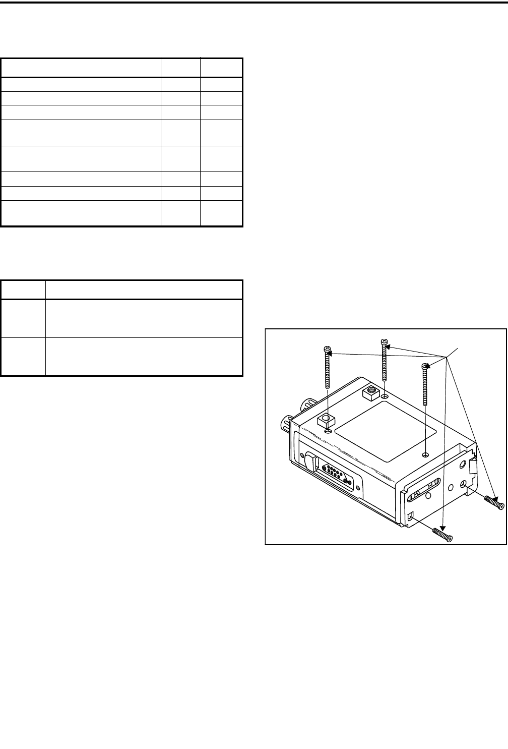
2. Remove the three screws in the back and two in the
bottom end that are indicated in Figure 1-1. Slide the
case off.
3. Removing the two screws in the end also allows the
front panel to be removed. Simply lift it outward if
desired. If you do not want to remove the front
panel, temporarily replace one of the end screws.
CAUTION
Excessive flexing of the ribbon cables may result in
broken traces.
Figure 1-1 Removing Case Screws
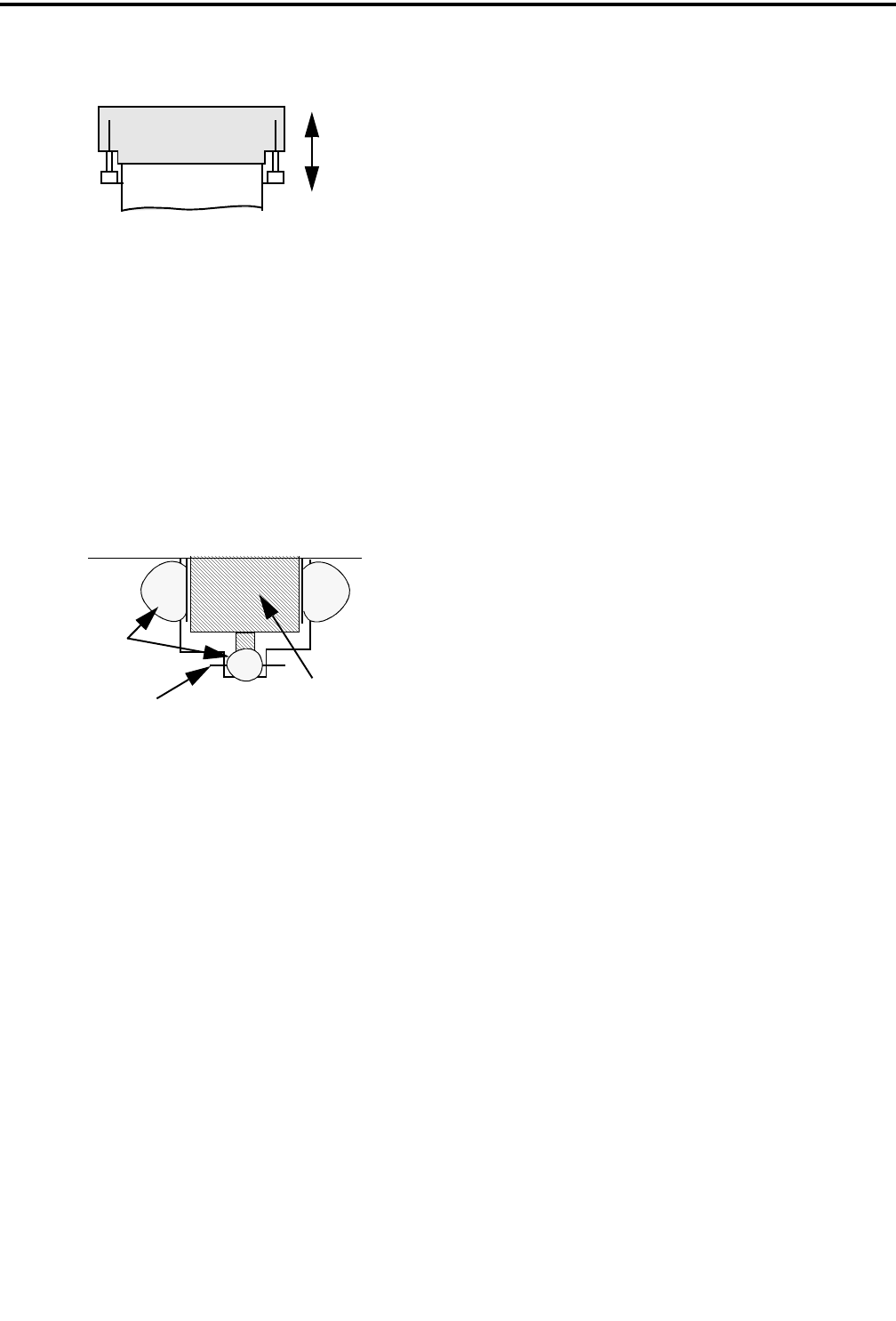
1.11.3 UNPLUGGING FLEX CABLES
The flex cable to the front panel and also the
accessory jack and PTT switch flex cables to the logic
board are inserted into a locking-type connector. To
release the cable so that it can be removed from the
connector, the locking tangs must be pulled out as
shown in the following illustration.
Table 1-2 Material Classification
Typical Hazard Group Class
Acetylene A I
Hydrogen B I
Ethylene, ethyl ether, cyclopropane C I
Gasoline, naphtha, butane, propane,
alcohol, acetone, benzol, natural gas DI
Metal dust including aluminum, mag-
nesium, and their alloys EII
Carbon black, coal, or coke dust F II
Flour, starch, or grain dusts G II
Ignitable fibers/flyings such as rayon
or cotton -III
Table 1-3 Area Classification
Division Area
1 An area where there is or could be an explosive
atmosphere most of the time in normal opera-
tion
2 An area where an explosive atmosphere exists
only as a result of a fault (something going
wrong)
REMOVE
THESE
SCREWS
GENERAL INFORMATION
1-7 November 1999
Part No. 001-7780-500
1.11.4 REMOVING RF UNIT
1. Remove the five screws attaching the shield to the
PC board.
2. Remove the two screws securing the RF power
module to the chassis. Then remove the four stand-
offs attaching the RF board to the chassis.
3. Unsolder the antenna connector from the PC board
by removing the solder at the locations shown in the
following illustration.
4. Remove the PC board by lifting it upward. The RF-
to-logic board connector under the IF board must
unplug, so some resistance may be encountered. Do
not pull on the IF or PLL board assemblies because
they can be easily damaged.
1.11.5 REMOVING LOGIC UNIT
1. Remove the top panel knobs. Then remove the
spanner nuts on the quick select and on-off/volume
switches. Remove the plastic top panel.
2. Unplug the flex cables from the front panel, acces-
sory connector, and PTT switch as described in
Section 1.11.3.
3. Unsolder the DC power flex circuit attached to the
logic unit near the accessory flex circuit connector.
4. Remove the four screws attaching the logic unit to
the chassis.
5. Remove the logic unit by carefully lifting it
outward.The RF-to-logic board connector under the
IF board must unplug, so some resistance may be
encountered. There is a pry hole (indicated by an
arrow) on the lower left edge of the PC board.
LOCK
UNLOCK
WIRE IN
PC BD ANTENNA
CONNECTOR
SOLDER

GENERAL INFORMATION
1-8
November 1999
Part No. 001-7780-500
7780 SPECIFICATIONS
The following are general specifications intended for use in testing and servicing the transceiver. For current advertised
specifications, refer to the 7780 product information sheet available from your E.F. Johnson sales representative. Specifica-
tions are subject to change without notice. GENERAL
Operating Mode SMARTNET/SmartZone (trunked) and conventional (non-trunked)
Frequency Range 806-824 MHz transmit (SMARTNET/SmartZone/conventional standard)
851-869 MHz transmit (conventional talk-around)
851-869 MHz receive
Zones Programmable Up to 16
Channels Programmable Up to 16 per zone (256 total)
Transmit/Receive Separation 45 MHz standard, 0 MHz conventional talk-around
Channel Spacing 12.5 kHz - 2.5 kHz maximum deviation
25 kHz - 5 kHz max deviation standard, 4 kHz NPSPAC
Frequency Stability (tx and rx) 1.5 PPM –22° to +140° F (–30° to +60° C)
Dimensions(withbatteryandcontrols) 6.5”Hx2.2”Wx1.2”D
166mmHx56mmWx30mmD
Weight (with battery) 18 oz. (515 g)
Power Source 7.5 VDC nickel metal-hydride (NiMH) battery pack, 1300 maH
Typical Battery Life (5-5-90) 7.5 hours (high power), 8.6 hours (low power)
Compliance FCC parts 15 and 90
Circuit Protection 3-ampere fuse
RECEIVER
Sensitivity 0.35 µV (12 dB SINAD)
Selectivity –65 dB at 25 kHz
Spurious and Image Rejection –60 dB at 25 kHz
Intermodulation –65 dB at 25 kHz
Audio Output Power Internal Speaker - 0.5 watt (16-ohm load)
External - 1.5 V rms (680-ohm load)
Audio Distortion Less than 5% at rated power (0.5 watt)
Audio Response +1, –3 dB at 6 dB per octave de-emphasis characteristic
Channel Spread 18 MHz
Current Drain Standby (squelched) - 92 mA maximum
Rated Audio Output - 300 mA maximum
TRANSMITTER
High RF Power Output
Standard Models 3.0 watts (standard mode)
2.5 watts (conventional talk-around mode)
Intrinsically Safe Models 2.0 watts at less than 1.55 A (standard mode)
1.8 watt at less than 1.60 A (talk-around mode)
Low RF Power Output 1.0 watt (all models and modes)
Spurious and Harmonic –60 dB at 25 kHz
FM Hum and Noise –40 dB at 25 kHz
Audio Distortion 5% maximum at 1 kHz
Audio Frequency Response +1, –3 dB from a 6 dB per octave pre-emphasis characteristic
Audio Modulation 11K0F3E, 16K0F3E, 14K0F3E
Channel Spread 18 MHz (no degradation); 63 MHz (talk-around)
Current Drain (maximum) Low Power - 1.3 ampere
High Power Standard Models -1.75 ampere (2.0 ampere talk-around)
Load Impedance 50 ohms
Duty Cycle (6-6-48 seconds) 5% (Transmit-Receive-Standby)
2-1 November 1999
Part No. 001-7780-500
TRANSCEIVER OPERATION
SECTION 2 TRANSCEIVER OPERATION
2.1 FEATURES
2.1.1 GENERAL FEATURES
•16 zones with home zone select
•16 channels per zone (256 channels total)
•Radio-wide scan
•Time-out timer
•LCD 8-character alphanumeric display with 12
status annunciators
2.1.2 CONVENTIONAL FEATURES
•Channel scan with three user programmable scan
lists
•Priority channel sampling
•Busy channel lockout (transmit disable on busy)
•Monitor mode
•Call Guard® (CTCSS/DCS) squelch control
•Penalty timer
•Conversation timer
•Repeater talk-around
•DTMF/ANI signaling
•User selectable power output
•Selectable channel display mode
2.1.3 SMARTNET™ II FEATURES
•Group, Enhanced Private Conversation™, Private
Conversation II™, and telephone calls
•Call Alert™ (paging)
•Emergency calls
•Messaging
•Priority monitor scanning
•Failsoft operation
•Dynamic regrouping
2.1.4 SMARTZONE® FEATURES
•Site trunking
•Site search
•Site lock/unlock
2.1.5 LIMITED/ENHANCED KEYPAD
FEATURES
Limited (3-key) and Enhanced (15-key) models
of this transceiver are available. Most features avail-
able with the enhanced keypad model are also avail-
able with the limited keypad model. The features not
available with the limited (3-key) model are as
follows:
•Since the DTMF keys are not available, it is not
possible to dial telephone numbers or manually
send DTMF tones. However, telephone calls can
still be placed using prestored numbers.
•With conventional standard scanning, only one scan
list is available and it is not user programmable.
•With SMARTNET/SmartZone operation, direct
entry of unit ID numbers is not available when
making private calls or sending pages. However,
these calls can still be made by recalling the ID from
a prestored list.
2.2 CONTROLS AND DISPLAY
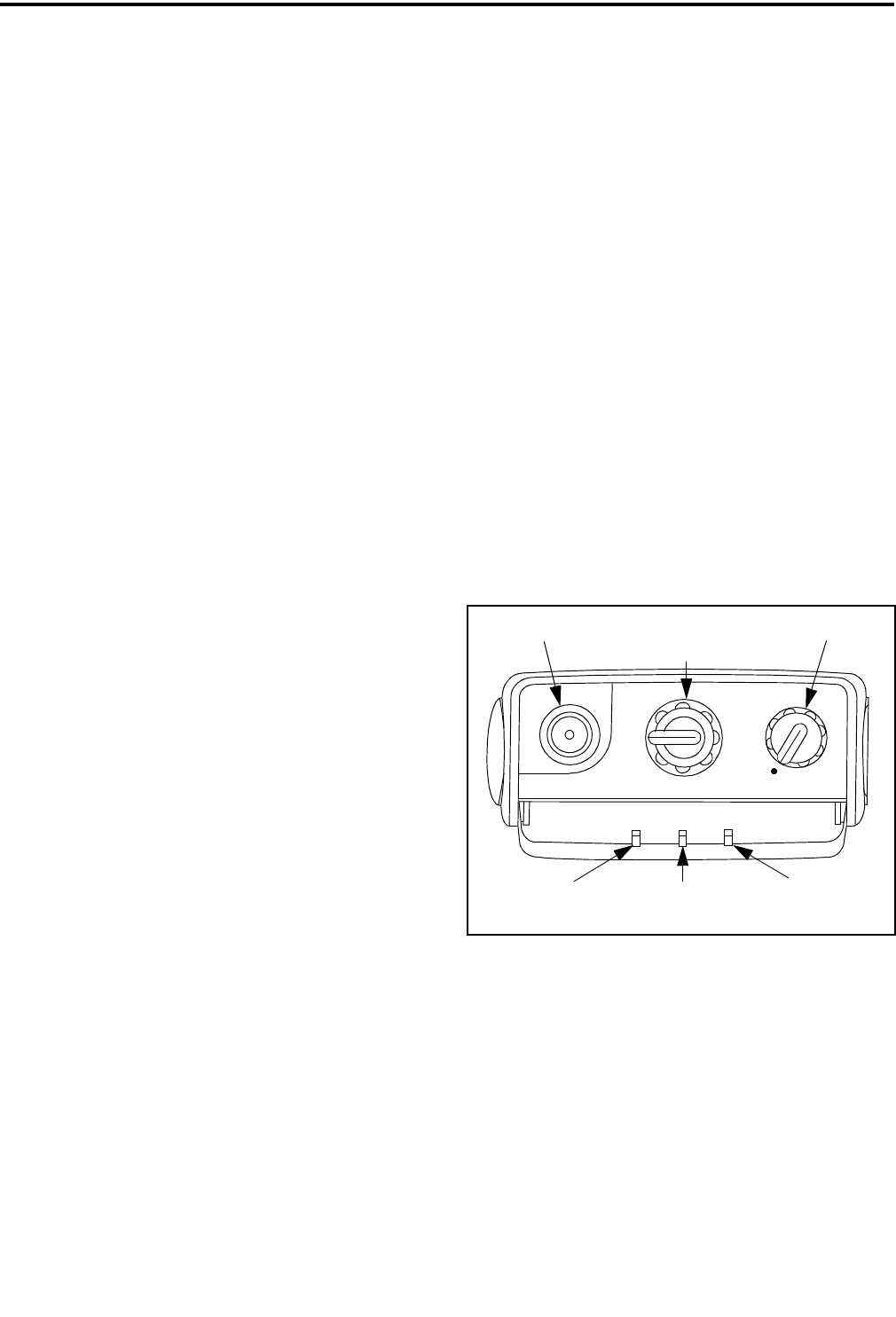
2.2.1 TOP PANEL CONTROLS
On-Off Volume - Turning this knob clockwise turns
power on and sets the volume level. Turning it coun-
terclockwise to the detent turns power off.
Channel Select Switch - Selectsupto16prepro-
grammed channels. The selected channel is also indi-
catedinthedisplay.
Antenna Jack - Connection point for the antenna.
BATT
RX
TX
OFF/VOL
6
7
8
5
4
3
2
1
12
1110 9
16
15
14
13
Transmitter
Keyed
Receive Signal
Detected
Low
Battery
On-Off/Volume
Antenna Jack
Channel Select Sw
TRANSCEIVER OPERATION
2-2
November 1999
Part No. 001-7780-500
Figure 2-1 Limited Keypad Model
2.2.2 TOP PANEL INDICATORS
TX Indicator (Red) - Indicates when the transmitter
is keyed.
RX Indicator (Green) - Indicates that the channel
may be busy because a carrier is being detected.
Low-Battery Indicator (Amber) -
Indicates that the battery charge is
getting low and recharging will
soon be required.
2.2.3 SIDE CONTROLS
AUX (Auxiliary) - This is a dealer
programmable switch that can con-
trol various functions (see Section
2.3.4). With the limited keypad
(3-key) version, it is also the CLR
key.
PTT (Push-To-Talk) - This switch
is pressed to key the transmitter.
The red TX indicator on the top
panel lights when the transmitter is
keyed.
Figure 2-2 Full Keypad Model
FCN (Function) - This is a dealer programmable
switch that can control various functions (see Section
2.3.4).
Battery Release Button - Pushing this spring-loaded
button upward releases the battery so that it can slide
off the radio for recharging or replacement. Turn
power off before removing the battery.
Accessory Connector (not shown) - This connector is
on the opposite side of the transceiver, and it is the
connection point for optional accessories such as a
speaker-microphone.
2.2.4 FRONT PANEL KEYS (LIMITED KEYPAD
MODEL)
The following keys are located on the front panel
shown in Figure 2-1:
F1, F2, F3 - Each of these keys can be dealer pro-
grammed to control a specific function (see Section
2.3.4). These keys are also used in menus to scroll left
( ), scroll right ( ), and for the Enter (ENT) func-
tion. The top key on the side (AUX) functions as a
CLR key in menus.
F2
F1 F3
ENT
F1
1
F3
ENT
CLR
F2
23
6
5
4
789
#
0
*
AUX
PTT
FCN
Battery Release
Button
TRANSCEIVER OPERATION
2-3 November 1999
Part No. 001-7780-500
Figure 2-3 Display
Low Battery
Monitor
Mode
Talk-Around
Mode
Radio-
Wide
Scan
In Scan
List
Scan
Enabled
Low Tx
Power Busy
Channel
Priority
Channel
Private
Call
Telephone
Call
Keypad
Locked
Keypad Prog.
Mode
Alphanumeric
Display
2.2.5 FRONT PANEL KEYS (FULL KEYPAD
MODEL)
The following keys are located on the front panel
shown in Figure 2-2:
0-9-These keys enter a number whenever number
entry is required.
F1 - This key is dealer programmable to control a
specific function (see Section 2.3.4).
F2 - This key is dealer programmable to control a
specific function (see Section 2.3.4). In addition, in
menus, it provides the Clear (CLR) function.
F3 - This key is dealer programmable to control a
specific function (see Section 2.3.4). In addition, in
menus, it provides the Enter (ENT) function.
-This key is dealer programmable to control a
specific function (see Section 2.3.4). In addition, in
menus, it provides the Scroll Left () function.
-This key is dealer programmable to control a
specific function (see Section 2.3.4). In addition, in
menus, it provides the Scroll Right () function.
2.2.6 DISPLAY
The following information is indicated by the
display shown in Figure 2-3:
Alphanumeric Display - This eight-character area of
the display indicates alphanumeric messages and
feature selection information.
S-Standard scanning is enabled (see Section 2.3.11).
Standard and radio wide scanning cannot be enabled at
thesametime.
- The current conventional channel is in the
standard scan list (see Section 2.3.11).
- Telephone (interconnect) mode is selected
with SMARTNET/SmartZone channels only (Section
2.5.6).
- Radio-wide scan is enabled (see Section
2.3.11).
- Repeater talk-around is enabled (see Section
2.4.9).
C-A SMARTNET/SmartZone private call is occur-
ring (see Sections 2.5.4 and 2.5.5).
- The conventional monitor mode is enabled (see
Section 2.4.4).
P-The selected conventional channel is a priority
channel (see Section 2.4.12).
LOW -Low transmit power is selected on a conven-
tional channel (see Section 2.4.10).
*
#

TRANSCEIVER OPERATION
2-4
November 1999
Part No. 001-7780-500
BUSY -A busy system or transmit channel is being
detected by the Busy Channel Lockout feature (see
Section 2.4.5).
- The battery needs recharging (see Section
2.3.6).
- The keypad has been locked by pressing the
Keypad Lock option switch (see Section 2.3.5).
2.3 GENERAL OPERATION
2.3.1 INTRODUCTION
This section (2.3) describes features available
with both trunked and conventional operation. For
information on features unique to conventional chan-
nels, refer to Section 2.4, and for information on
features unique to SMARTNET/SmartZone channels,
refer to Section 2.5.
2.3.2 TURNING POWER ON AND SETTING
VOLUME
Power is turned on and off by the On-Off/Volume
switch on the top panel. When power is initially turned
on, an alert tone sounds and the radio software version
is momentarily displayed. If a SMARTNET/Smart-
Zone channel is selected, the zone alias is then
displayed followed by the unit ID (see page 13). The
selected channel is then indicated.
To turn power off, turn the On-Off/Volume knob
counterclockwise until a click occurs. The display may
remain on for a few seconds after power is turned off.
It is recommended that power not be turned back on
again until the display is blank.
The relative volume level can be determined by
noting the position of the index on the On-Off/Volume
knob. To enable a reference tone for setting the
volume, proceed as follows:
•If key press tones are enabled (see Section 2.3.10),
a short tone sounds when front panel keys are
pressed.
•If a conventional channel is selected and the
Monitor option switch is programmed (see Section
2.4.4), pressing that switch unsquelches/squelches
the receiver and either voice or background noise is
heard. If a SMARTNET/SmartZone channel is
selected, the receiver cannot be manually
unsquelched.
2.3.3 BACKLIGHT
The backlight for the display and keypad can be
manually turned on by pressing the Backlight option
switch if it is available. It can also be dealer
programmed to automatically turn on when any key is
pressed. It then automatically turns off after the
programmed delay so that battery drain is minimized.
2.3.4 OPTION SWITCHES
The programmable option switches are as
follows, and the programmable functions are shown in
Table 2-1.
•F1, F2, F3
•,#(full keypad 15-key models only)
•AUX, FCN (on side)
If the radio is programmed with both conven-
tional and SMARTNET/SmartZone channels (see
Section 2.3.12), these option switches can control a
different set of functions for each channel type. For
example, the F1 switch could select Hi/Lo Power
when a conventional channel is selected and Private
Calls when a SMARTNET/SmartZone channel is
selected. If no option switch has been programmed to
control a particular function, that function may not be
available or may be in a fixed mode.
2.3.5 KEYPAD LOCK
If the Keypad Lock option switch has been
programmed, the keypad can be locked (disabled) to
prevent keys from being accidentally pressed. To lock
the keypad, press this switch and a locked keypad is
indicated by the icon in the display. To unlock the
keypad again, press and hold the Keypad Lock switch
until a tone sounds (approximately 1 second). The
keypad can also be disabled by programming. It is
then permanently disabled and cannot be re-enabled
by the user.
*

TRANSCEIVER OPERATION
2-5 November 1999
Part No. 001-7780-500
2.3.6 LOW BATTERY INDICATION
When the battery voltage falls below a preset
level, the icon appears in the display. This
icon stays on until power is turned off. In addition, the
following low battery indications may be programmed
to occur:
•The amber BATT indicator on the top panel lights.
•A beep sounds once per minute in the standby mode.
•A beep sounds each time the PTT switch is pressed.
The battery should be recharged as soon as prac-
tical after a low battery indication appears. Refer to
Section 5 for more battery information. There is also a
battery saver function that can be enabled by program-
ming. This function uses the RSSI level to determine
when the site is very near and then automatically
switches to the low transmit power output level.
2.3.7 CHANNEL AND ZONE SELECTION
Channel Select
To change the current channel, rotate the 16-posi-
tion channel selector knob on the top panel to the
desired position. With SMARTNET/SmartZone chan-
nels, the channel is always indicated by alias (name).
With conventional channels, the channel number or
frequency may also be displayed (see Section 2.4.2).
Zone Select
A zone is a group of up to any 16 conventional
and SMARTNET/SmartZone channels defined by
programming (see Section 1.2.4). Up to 16 zones can
be programmed for a total of 16 x 16 or 256 channels.
One use of zones may be to select groups of channels
programmed for operation in different geographical
areas or radio systems. Zones are selected as follows:
1. Press the Zone option switch and the alias (name) of
the current zone is flashed in the display.
2. Use the number keys to enter the desired zone
number or scroll through the available zones using
the and keys.
3. Once the desired zone is displayed, press the ENT
key or wait 4 seconds.
2.3.8 HOME ZONE
The radio can be programmed with a home zone.
Then when power is turned on, the radio can be
programmed so that either the home or last selected
zone is automatically selected.
If the Home Zone option switch is programmed,
itcanbeusedtoquicklyselectorchangethehome
zone. To select the home zone, momentarily press this
switch. Then to change the home zone to the currently
selected zone, press and hold this switch until a tone
sounds (approximately 1 second).
2.3.9 TIME-OUT TIMER
The time-out timer disables the transmitter if it is
keyed for longer than the programmed time. On each
Table 2-1 Option Switch Functions
Function Conv.
Mode
Smart-
Net
Mode
Smart-
Zone
Mode
See
Section
Backlight X X X 2.3.3
Call Alert X X 2.5.7
Call Response X X 2.5.4, 2.5.5
Displayed Information X 2.4.2
Emergency X X 2.5.10
High/Low Power X 2.4.10
Home Zone X X X 2.3.8
Keypad Lock X X X 2.3.5
Keypad Programming X 2.7
Message X X 2.5.8
Monitor X 2.4.4
Normal/Selective X 2.4.6
Phone X X 2.5.6
Priority X 2.4.12
Private Call X X 2.5.4, 2.5.5
Radio Wide Scan X X X 2.3.11
Repeater Talk-Around X 2.4.9
Scan X X X 2.3.11
Scan Edit X 2.4.11
Site Lock X 2.5.14
Site Search X 2.5.14
Status X X 2.5.9
Tones On-Off X X X 2.3.10
Zone X X X 2.3.7

TRANSCEIVER OPERATION
2-6
November 1999
Part No. 001-7780-500
channel it can be programmed for times from 15
seconds up to 3 minutes, 45 seconds or disabled (not
used). If the transmitter is keyed continuously for
longer than the programmed time, the transmitter is
disabled and an invalid condition tone sounds. Five
seconds before time-out occurs, an alert tone sounds to
indicate that time-out is approaching. The timer and
tone are reset by releasing the PTT switch.
One use of this feature is to prevent a channel
from being kept busy for an extended period by an
accidentally keyed transmitter. It can also prevent
possible transmitter damage caused by transmitting for
an excessively long period. Conventional channels can
also be programmed with the Penalty and Conversa-
tion timers that are described in Sections 2.4.7 and
2.4.8.
2.3.10 TONE ENABLE/DISABLE
The supervisory tones (see Section 2.6) can be
enabled and disabled by the Tones On-Off option
switch if it is programmed. When tones are enabled by
this switch, “TONE ON” is momentarily displayed
and a tone sounds. Conversely, when tones are
disabled, “TONE OFF” is displayed and no tone
sounds. If the Tones On-Off option switch is not
programmed, tones are fixed in the on or off mode by
programming.
2.3.11 SCANNING
Introduction
Scanning cycles through a list of channels, called
a “scan list”, checking each for messages. When a
message is detected that your transceiver is
programmed to receive, scanning stops and the
message is received. Shortly after the message is
complete, scanning resumes (unless it has been
disabled).
There are two basic scan modes: Standard and
Radio Wide. The Standard mode is unique to the type
of channel selected (conventional or SMARTNET/
SmartZone), and the Radio Wide mode is the same
regardless of the channel type selected. Only one of
these scan modes can be enabled at a time. Therefore,
if standard scanning is enabled while radio wide scan-
ning is occurring, radio wide scanning is automatically
disabled and vice versa. More information on these
modes follows.
Standard Scanning
Standard scanning monitors only channels that
are the same type as that currently selected. There-
fore, if a conventional channel is selected, only
conventional channels are scanned, and if a
SMARTNET channel is selected, only SMARTNET
channels are scanned. Standard scanning is turned on
andoffbytheScanoptionswitchasfollows.Ifthis
switch is not programmed, standard scanning is not
available.
•To turn standard scanning on, press the Scan option
switch. Scanning is enabled when the “S”iconis
indicated in the upper left corner of the display and
SCAN x (conventional) or SCAN ON
(SMARTNET/SmartZone) is briefly displayed. The
“x” is the number of the conventional scan list (1, 2,
or 3) that is selected. Refer to Section 2.4.11 for
more information.
•To turn scanning off, press the Scan option switch
again. The “S” icon is then no longer indicated and
“SCAN OFF” is briefly displayed.
•If the zone or channel is changed while scanning is
selected, scanning continues on the same or a
different scan list (see scan list information which
follows).
Radio Wide Scanning
Radio wide scanning monitors the channels in the
preprogrammed radio wide scan list (see information
whichfollows).Thislistmaycontainupto16chan-
nels of any type (conventional or SMARTNET/Smart-
Zone) assigned to any zone. Radio wide scanning is
turned on and off by the Radio Wide Scan option
switch as follows. If this switch is not programmed,
radio wide scanning is not available.
•To turn radio wide scanning on, press the Radio
Wide Scan option switch. The icon is then
displayed continuously and “RWS ON” is displayed
briefly.

TRANSCEIVER OPERATION
2-7 November 1999
Part No. 001-7780-500
•To turn radio wide scanning off, press the Radio
Wide Scan option switch again. The icon is
then no longer indicated and “RWS OFF” is
displayed briefly.
•If the zone or channel is changed while radio wide
scanning, radio wide scanning continues normally.
Scan Resume Delay
When a message is received or transmitted while
scanning, there is a programmable delay before scan-
ning resumes. The delay after receiving a call prevents
another message from being received before a
response can be made, and the delay after transmitting
a call ensures that a response is heard to your call
instead of another message occurring on some other
channel.
Standard Mode Scan List
NOTE: The selected channel is always scanned.
With conventional operation when using the full
keypad (15-key) model, up to three scan lists can be
programmed. The list that is scanned is selected by the
Scan option switch as described in Section 2.4.11.
Selecting another conventional channel does not
change the current scan list. In addition, the scan lists
are user programmable if the Scan Edit option switch
is programmed. With limited keypad (3-key) models,
only Scan List 1 can be scanned, and it is not user
programmable.
With SMARTNET/SmartZone operation, each
channel can be programmed so that one of up to three
different scan lists is automatically selected. Channels
can also be programmed so that scanning is automati-
cally disabled when they are selected. SMARTNET/
SmartZone scan lists are not user selectable or
programmable.
Radio Wide Mode Scan List
With radio wide scanning, there is only one
preprogrammed scan list available regardless of the
type of channel selected, and it is not user
programmable.
Determining Which Channels are in Scan List
Channels in the radio wide and standard
SMARTNET/SmartZone scan lists are not indicated.
With standard conventional scanning, the selected
channel is in the current scan list if the box icon
(around “S”) is indicated in the upper left corner of the
display.
Nuisance Channel Delete
With standard scanning, both conventional and
SMARTNET/SmartZone channels can be temporarily
deleted from the scan list. This feature is not available
with radio wide scanning. Proceed as follows:
NOTE: The selected channel and conventional priority
channels cannot be deleted from the scan list.
1. While receiving a message on the channel to be
deleted, press and hold the Scan option switch until
the alert tone sounds (about 1 second).
2. The channel is then deleted and scanning of the
remaining channels in the scan list resumes.
3. Deleted channels are added back into the scan list if
either of the following occur:
•Scanning is turned off and then on again using the
Scan switch.
•Transceiver power is turned off and then on again.
2.3.12 CONVENTIONAL AND SMARTNET/
SMARTZONE OPERATION
Introduction
Each selectable channel is programmable for
either conventional, SMARTNET, or SmartZone oper-
ation. For example, Zone 1/Channel 1 could be a
conventional channel, Zone 1/Channel 2 a
SMARTNET channel, and so on. More information on
these modes follows.
Conventional Operation
This is a non-trunked operating mode which
accesses independent radio channels (there is no auto-
matic access to several channels as with trunked oper-

TRANSCEIVER OPERATION
2-8
November 1999
Part No. 001-7780-500
ation). Monitoring before transmitting may not occur
automatically in this mode, so the channel may have to
be manually monitored before transmitting (see
Section 2.4.3). Selecting a conventional channel
selects a transmit and receive frequency and other
parameters such as Call Guard squelch coding.
SMARTNET/SmartZone Operation
This is a trunked operating mode that uses ID
codes to select which mobiles are being called and
which calls are received. Monitoring is performed
automatically and special messages and tones indicate
busy and out-of-range conditions. Enhanced features
include roaming (SmartZone only), telephone, private,
and emergency calls, Call Alert, and messaging. Oper-
ating features unique to SMARTNET/SmartZone
channels are described in Section 2.5.
This radio supports only the SMARTNET II
trunking protocol. It does not support the SMARTNET
I (also referred to as Type I) protocol. When a
SMARTNET or SmartZone channel is selected or the
radio is powered up on a SMARTNET/SmartZone
channel, it searches for a control channel and attempts
to register on the radio system. Once a control channel
is found, the alias (name) of the selected channel is
displayed. If a control channel could not be found
(because of an out of range condition or the system ID
is not correct, for example), “NO SYS” is displayed
and the radio continues to search for a control channel.
The control channel transmits and receives
system information to and from all radios registered on
the system. Therefore, once a control channel is found,
it is continuously monitored for incoming call infor-
mation and is used to make call requests. The radio
automatically changes to a traffic channel to place and
receive calls and then returns to the control channel
when the call is complete.
2.4 CONVENTIONAL FEATURES
2.4.1 INTRODUCTION
The following information describes features
unique to the conventional operating mode (described
briefly in Section 2.1.2). Refer to Section 2.3 for infor-
mation on features common to all operating modes,
andtoSection2.5forinformationonfeaturesunique
to the SMARTNET/SmartZone mode.
2.4.2 DISPLAY MODE SELECTION
If the Displayed Information option switch is
programmed, the display mode used to indicate
conventional channels can be user selected. Pressing
this switch cycles between the following modes. The
selected mode does not change when power is turned
off. If the Displayed Information option switch is not
programmed, the Alias mode is always used.
Alias - The preprogrammed alphanumeric tag for the
channel is displayed.
Number - The channel number from 1-16 is
displayed.
Frequency - The receive frequency of the selected
channel is displayed in megahertz.
2.4.3 MONITORING BEFORE TRANSMITTING
With conventional operation, channels are moni-
tored automatically or manually as follows:
Automatic Channel Monitoring
If the selected channel is programmed for the
Busy Channel Lockout feature, monitoring is
performed automatically. Refer to the description of
this feature in Section 2.4.5 for more information.
Manual Channel Monitoring
The automatic monitoring just described may not
be programmed or it may occasionally disable the
transmitter even if the channel is not in use. In this
case, the channel must be monitored manually as
follows:
Rx Indicator - With scanning disabled, note if the
green RX indicator on the top panel is on. If it is not,
the channel is not being used and the call can be
transmitted. If it is on, a carrier is being detected, so
the channel may be busy (see next paragraph).
Monitor Mode - There may be times when the busy
indication is displayed even though no one is using
the channel. Monitoring should then be performed
by disabling Call Guard squelch using the Normal/
Selective option switch as described in Section
2.4.6 or the monitor mode described next.

TRANSCEIVER OPERATION
2-9 November 1999
Part No. 001-7780-500
2.4.4 MONITOR MODE
The monitor mode temporarily disables squelch
control features (such as Call Guard squelch) so that
all messages are heard on the selected channel. It also
overrides the Busy Channel Lockout feature (see next
section) and temporarily halts scanning.
To monitor the selected transmit channel, select
the monitor mode by briefly pressing the Monitor
option switch (if available). The icon is displayed
and the receiver unsquelches (even if no carrier is
detected). To disable the monitor mode and return to
normal operation, press the Monitor switch a second
time.
To monitor the selected receive channel instead of
the transmit channel, press and hold the Monitor
switch until the alert tone sounds (approximately 1
second). This function may be useful, for example,
during weak signal conditions if intermittent
squelching makes a message difficult to understand.
2.4.5 BUSY CHANNEL LOCKOUT
The Busy Channel Lockout feature (also called
Transmit Disable On Busy) automatically disables the
transmitter if the channel is busy when the PTT switch
is pressed. When a busy condition is detected by this
feature, the transmitter is disabled, “BUSY” is indi-
cated in the lower part of the display, and a tone
similar to a standard telephone busy tone sounds until
the PTT switch is released. This feature is
programmed to operate in one of the following modes
on each channel:
Off - The transmitter keys even if the channel is busy.
Noise - The transmitter is disabled if any signal is
detected on the channel.
Tone - The transmitter is disabled if the detected
squelch coding is not correct.
If busy override is permitted by programming, it
is possible to transmit even when the transmitter is
disabled by this feature. Simply quickly release the
PTT switch and press it again.
2.4.6 CALL GUARD SQUELCH
General
Call Guard® squelch (also called CTCSS/DCS
signaling) can be programmed on conventional
channels. This feature eliminates distracting messages
intended for others using the channel by using a
subaudible tone or digital code to control the squelch.
This tone or code is unique to a user or talk group on
that channel. It is transmitted by the mobile placing a
call, and if Call Guard squelch is programmed in the
mobile receiving the call, it must detect the correct
tone or code to receive the call.
Call Guard Squelch Enable/Disable
To disable Call Guard (Selective) squelch so that
all messages on the selected or scanned channels are
heard, press the Normal/Selective option switch if
programmed. The receiver unsquelches only if a
carrier is detected. To re-enable Call Guard squelch,
press the Normal/Selective switch again.
When Call Guard squelch is disabled by this
switch, “SQ NORM” is flashed on the lower line of
the display, and when it is enabled, “SQ SLCT” is
flashed. The selected mode does not change when
other channels are selected or power is cycled. Call
Guard squelch can also be disabled by the monitor
mode described in Section 2.4.4.
Changing the Call Guard Code
If using the full keypad (15-key) model and the
ability to change Call Guard codes has been enabled
by programming, the transmit and receive codes from
one channel can be temporarily or permanently reas-
signed to all channels of the current zone. Proceed as
follows:
1. Using the number keys, enter the number of the
channel that is programmed with the code you want
to reassign to all channels (only channels 1-9 can be
selected). See Section 2.4.2 for information on how
to display channel numbers.
2. The display then briefly indicates “CODE x”, where
“x” is the key that was pressed. The codes assigned

TRANSCEIVER OPERATION
2-10
November 1999
Part No. 001-7780-500
to that channel are then reassigned to all the other
channels in the current zone. The reassignments
remain in effect even after power is cycled.
3. To restore all Call Guard codes in the current zone
totheoriginalsettings,pressthe“0”key.
2.4.7 PENALTY TIMER
A penalty timer may be programmed on conven-
tional channels to prevent transmissions for a period of
time after the time-out timer described in Section 2.3.9
disables the transmitter. The penalty timer starts when
the PTT switch is released after the transmitter has
been disabled. If the PTT switch is pressed during the
penalty time, the time-out indication occurs again. A
beep sounds when the penalty timer expires and the
transmitter can then be keyed.
2.4.8 CONVERSATION TIMER
A conversation timer can be programmed on
conventional channels to limit the total length of a
conversation rather than just the length of each trans-
mission as with the time-out timer. This timer is reset
when the time between transmissions exceeds the
penalty time just described. A warning tone sounds 5
seconds before the conversation timer expires. When it
expires, the transmitter is disabled and a warning tone
sounds. The transmitter remains disabled for the
length of the penalty time, and a beep sounds when it
can be keyed again.
2.4.9 REPEATER TALK-AROUND
Normally, all transmissions go through a repeater
which usually increases range. However, if out of
range of the repeater, you cannot talk to anyone else on
that channel even though the mobile you are calling
may be only a short distance away. To allow communi-
cation when this situation occurs, repeater talk-around
can be used to transmit on the receive frequency. This
allows direct communication with a mobile without
going through a repeater.
Repeater talk-around can be selected if the
Repeater Talk-Around option switch is programmed.
When talk-around is enabled by this switch, the
icon is displayed and “RTA ON” is flashed in the
display. Then when it is disabled by pressing this
switch again, that icon is no longer displayed and
“RTA OFF” is flashed. Changing channels or turning
power off does not change the selected talk-around
mode.
2.4.10 POWER OUTPUT SELECT
If the High/Low Power option switch is
programmed and power selection is permitted on the
current channel by programming, either high or low
transmitter power can be selected. Generally, the high
power setting transmits longer distances but uses more
battery power, and the opposite occurs with the low
power setting. When the low power is selected on the
current channel, “LOW” is indicated continuously
near the bottom of the display.
Pressing the High/Low Power switch toggles the
power setting. The new level is flashed in the display
when this switch is pressed as “HI POWER” or “LO
POWER”. If power selection is not permitted on the
channel, the fixed power level is flashed and no power
change occurs. Turning power off or changing chan-
nels does not change the power setting selected for a
channel.
2.4.11 CONVENTIONAL MODE SCANNING
General
The following information describes scanning
features unique to conventional operation. Scan opera-
tion common to all modes is described in Section
2.3.11, and scan operation unique to SMARTNET/
SmartZone operation is described in Section 2.5.12.
Selecting a Scan List
When standard scanning with full keypad (15-
key) models, one of up to three scan lists can be
selected. These lists can be user programmed as
described in the information which follows. With
limited keypad (3-key) models, only one scan list is
available and is not user programmable. However,
nuisance channels can still be temporarily deleted as
described in Section 2.3.11.
Proceed as follows to select a scan list with full
keypad models:

TRANSCEIVER OPERATION
2-11 November 1999
Part No. 001-7780-500
1. Press the Scan option switch to enable scanning.
The currently selected scan list is momentarily
indicated as “Scan x”, where “x” is the list number
(1-3).
2. To select one of the other lists, press the number key
corresponding to the desired list (1-3) and the
selected list is then momentarily displayed as “Scan
x”. The selected scan list is stored in memory and
does not change until this procedure is repeated.
Programming a Scan List
With full keypad (15-key) models, each of the
three scan lists is user programmable if the Scan Edit
option switch is programmed and user programming
of the list is allowed. Otherwise, the channels in these
lists are determined by dealer programming. User scan
list programming is not available with limited keypad
(3-key) models. Proceed as follows to program a scan
list:
1. Make sure all scanning is off (neither the standard
scan “S” icon or radio-wide scan icon is
displayed).
2. Press the Scan Edit option switch and then within 2
seconds press the number key corresponding to the
scan list you want to edit (1-3). If a list is not
selected within the allotted time, the last active
conventional standard scan list is automatically
selected. The selected list is indicated as “SCAN x”.
If user programming is disabled on a list, “NO
LIST” is momentarily displayed and it cannot be
edited.
3. Select the channel you want to add or delete using
the and keys. To change zones, press the F1
key and select the new zone.
4. If the selected channel is in the scan list, the box
around “S” is indicated in the upper left corner
of the display. To add the channel to the scan list,
press the “1” key, and to delete the channel, press the
“2” key.
NOTE: The priority channel cannot be deleted (see
Section 2.4.12).
5. To exit this mode and save the changes, press the
ENT or CLR key.
Transmitting in Scan Mode
Each conventional scan list can be programmed
for one of the following modes. These modes deter-
mine if priority sampling occurs and also the channel
on which transmissions occur while scanning. Refer to
the next section for more information.
No Priority - No priority channel sampling occurs
when the list is selected. The radio transmits on the
selected channel.
Priority/Tx Priority - Priority sampling occurs and
the priority channel is the one programmed in the
selected scan list. The radio transmits on the priority
channel.
Priority/Tx Selected - Priority sampling occurs and
the priority channel is the one programmed in the
selected scan list. The radio transmits on the selected
channel.
Priority on Selected - The priority channel is always
the selected channel. The radio transmits on the
selected channel.
Talkback - No priority sampling occurs. The radio
transmits on the channel of a call while scanning is
halted. Then once scanning resumes, it transmits on
the selected channel.
2.4.12 PRIORITY CHANNEL SAMPLING
General
The priority channel sampling feature ensures
that when standard scanning, messages on the priority
channel are not missed while listening to a message on
some other channel. The transceiver can be
programmed so that the priority channel is a fixed
channel associated with the current scan list, the
currently selected channel, or not used (see preceding
section). When the selected channel is a priority
channel, “P” is indicated in the upper right part of the
display.
Priority channel sampling occurs only with Stan-
dard conventional scanning. It does not occur with
Radio Wide scanning, when listening to any type of
SMARTNET/SmartZone call, or when transmitting. A
series of “ticks” may be heard when the priority

TRANSCEIVER OPERATION
2-12
November 1999
Part No. 001-7780-500
channel is sampled while listening to a message on
some other channel.
The priority sampling times are programmed by
the following parameters:
Lookback Time A - This time determines how often
the priority channel is checked for activity. Times of
0.25-4.00 seconds in 0.25-second steps can be
programmed.
Lookback Time B - This time determines how often
the priority channel is checked once an incorrect Call
Guard (CTCSS/DCS) code is detected. Since it takes
much longer to detect an incorrect Call Guard signal
than a carrier, this time should be relatively long to
prevent the interruptions from making a message diffi-
cult to understand. Times of 0.5-8.0 seconds can be
programmedin0.5-secondsteps.
Changing The Priority Channel
If a specific priority channel is associated with
the current scan list, it can be changed if the Priority
option switch is programmed. Proceed as follows:
1. Make sure all scanning is off (neither the standard
scan “S” icon nor radio-wide scan icon
displayed).
2. Select the channel that you want to be the priority
channel using the channel selector switch on the top
panel. If the channel is in a different zone, also select
the appropriate zone.
3. Press the Priority option switch and the “P”iconis
displayed to indicate that the selected channel is
now the priority channel.
2.4.13 STANDARD CONVENTIONAL CALLS
Standard conventional calls are calls to or from
other mobile units on the selected channel. The proper
coded Call Guard signaling (see Section 2.4.6) may
need to be transmitted for them to receive your call
and also for you to receive their calls. Proceed as
follows to place and receive these calls:
Placing a Standard Conventional Call
1. Turn power on and set the volume as described in
Section 2.3.2. Select the channel programmed for
the mobile you want to call (see Section 2.3.7).
2. Monitor the channel automatically or manually as
described in Section 2.4.3.
3. Press the PTT switch and the call proceeds as
follows:
•If the Busy Channel Lockout feature is
programmed on the channel, the transmitter is
automatically disabled if the channel is busy (see
Section 2.4.5).
•Otherwise, busy and out-of-range conditions are
not indicated and speaking can begin after moni-
toring the channel.
4. Press (and hold) the PTT switch to talk and release
it to listen.
Receiving a Standard Conventional Call
1. Select or scan the channel programmed for the call
you want to receive (refer to Sections 2.3.11 and
2.4.11 for more scanning information).
2. When the call is received, press the PTT switch to
talk and release it to listen. If scanning, you may
have to respond before scanning resumes to ensure
that the response occurs on the channel of the call.
2.4.14 DTMF/ANI SIGNALING
DTMF (Dual Tone Multi-Frequency) tones can
be generated manually or automatically for ANI
(Automatic Number Identification) and other
purposes. The following options may be enabled by
dealer programming for each conventional channel:
DTMF Keypad - With full keypad (15-key) models
only, pressing 0-9, , or # on the keypad while
holding the PTT switch transmits the corresponding
tone until the key is released.
Pre-Tx ANI - A preprogrammed ANI sequence is
automatically sent when you press the PTT switch.
*

TRANSCEIVER OPERATION
2-13 November 1999
Part No. 001-7780-500
Post-TX ANI - A preprogrammed ANI sequence is
automatically sent each time you release the PTT
switch.
Disabled - All DTMF signaling is disabled.
2.5 SMARTNET/SMARTZONE FEATURES
2.5.1 INTRODUCTION
The following information describes features
unique to the SMARTNET and SmartZone operating
modes described briefly in Section 2.3.12. Refer to
Section 2.3 for information on features common to all
operating modes, and to Section 2.4 for information on
features unique to the conventional mode.
2.5.2 VIEWING UNIT ID
Each radio in a SMARTNET system is identified
with a system ID and Unit ID. To display the Unit ID,
make sure that a SMARTNET channel is selected and
then turn power off and then on again. The software
version number, current zone, and Unit ID are then
displayed in sequence. The six-digit Unit ID is
displayed as IDxxxxxx.
2.5.3 STANDARD GROUP CALLS
Standard group calls are between you and another
mobile, group of mobiles, or a control station (a radio
at a fixed location). Most calls you make will probably
be this type.
Placing a Standard Group Call
1. Turn power on and set the volume as described in
Section 2.3.2. Select the channel programmed for
the talk group you want to call (see Section 2.3.7).
A regular or announcement talk group can be
selected.
2. Press the PTT switch and when the alert tone
sounds, begin talking. Other indications that may
occur are as follows:
•If the busy tone sounds and “BUSY” is displayed,
the system is busy. Release the PTT switch and
wait for the call back tone to sound. Then press
the PTT switch within 3 seconds and begin
talking.
•If the radio system cannot be accessed within 500
ms of pressing the PTT switch, a continuous tone
sounds until the system is accessed or the PTT
switch is released.
•If your unit ID is invalid, the call is being made to
an invalid group ID, or group calls are not
allowed, “INVALID ID” is displayed and an alert
tone sounds.
Receiving a Standard Call
Group calls are automatically received if a
SMARTNET/SmartZone channel is selected. The
display continues to indicate the selected channel alias
(name) when a call is received.
2.5.4 ENHANCED PRIVATE CONVERSATION
CALLS
General
Private calls allow you to place a call to a specific
mobile unit. Either the Enhanced Private Conversa-
tion™ or Private Conversation II™ modes may be
programmed depending on the capabilities of the radio
system. The Enhanced Private Conversation mode is
described in the following information, and the Private
Conversation II mode is described in Section 2.5.5.
The Private Call option switch is required to
place these calls, and either that switch or the Call
Response option switch is required to receive them.
Proceed as follows.
Placing an Enhanced Private Conversation Call
This call can be initiated by selecting the unit ID
from a call list (list entry) or by directly entering it
using the keypad (direct entry). Direct entry is avail-
able with full keypad (15-key) models only. Proceed
as follows:
List Entry Method (All Models)
1. With a SMARTNET/SmartZone channel selected,
momentarily press the Private Call option switch.
The private call mode is indicated by “C”inthe
upper part of the display. The tag (alias) of the last
ID called is displayed if it matches an ID in your call
list. Otherwise, the last ID called is displayed.

TRANSCEIVER OPERATION
2-14
November 1999
Part No. 001-7780-500
2. Enter the index of the desired ID if you know it or
scroll through the list using the and keys
until you find the desired ID. Press the CLR key to
cancel the call.
3. Press the PTT switch or the ENT key to initiate the
call. The display then indicates the alias of the desti-
nation radio. Proceed to the bulleted list following
the next method for conditions that may occur next.
Direct Entry Method (Full Keypad Models Only)
1. With a SMARTNET/SmartZone channel selected,
press and hold the Private Call option switch until a
tone sounds (approximately 1 second). The last ID
called is displayed, and the private call mode is indi-
cated by “C” in the upper part of the display.
2. Using the 0-9 keys, enter the 6-digit ID of the
mobile unit you are calling. Press the key to
erase the last digit entered or press the CLR key to
cancel the call.
3. Press the PTT switch or the ENT key to initiate the
call. If the entered ID is invalid, “INVALID” is
momentarily displayed and the call is not initiated.
If the entered ID is valid, the display indicates the
alias of the ID if it matches an ID in your call list.
Otherwise, the ID you entered continues to be
displayed. Any of the following conditions may
then occur:
•If the radio you are calling is on the air, telephone
type “ringing” is heard for 20 seconds or until the
called party answers.
•If the called party answers and the call is
successful, the person’s voice is heard and the call
is carried on the same as a group call. To end the
call at any time, press the CLR key.
•If the called party does not answer within 20
seconds, “NO ANSWR” is displayed and a
continuous tone sounds. End the call by pressing
the CLR key.
•If the called radio is not in service, no ringing is
heard, “NO ACK” is displayed, and a continuous
tone sounds. End the call by pressing the CLR
key.
•If neither your radio nor the radio being called is
authorized to make unit-to-unit calls, “REJECT”
is displayed and a continuous tone sounds. End
the call by pressing the CLR key.
•If the called party answers but the radio system is
busy, four low tones sound and “BUSY” and
“WAIT” are alternately displayed. When the
system is no longer busy, the called party auto-
matically responds.
•If an out-of-range condition exists or the radio
system is not in service, “LOST CALL” is
displayed and a continuous tone sounds. End the
call by pressing the CLR key.
Receiving an Enhanced Private Conversation Call
These calls are automatically received if a
SMARTNET/SmartZone channel is selected. Proceed
as follows:
1. When a call is received, a recurring unit call tone
(three beeps) sounds for up to 20 seconds, and
“CALL RCV” and the current channel alias are
alternately displayed.
2. To answer the call, press the Private Call option
switch and then the PTT switch and begin talking.
The private call mode is indicated by “C”inthe
upper part of the display. The alias of the incoming
call is displayed if the ID is in your call list. Other-
wise, the unit ID is displayed. NOTE: If the Private
Call option switch is not pressed before the PTT
switch, a group call is transmitted on the selected
group.
•To end the call when the conversation is complete
or at any other time, press the CLR key.
•If unit-to-unit (private) calls are not permitted
(Private Call switch not programmed), press the
Call Response option switch, if available, to
answer the call.
•If the call is not answered within 20 seconds, it is
automatically terminated.
•If the radio system is busy, four low tones sound
and “BUSY” and “WAIT” are alternately

TRANSCEIVER OPERATION
2-15 November 1999
Part No. 001-7780-500
displayed. When the system is no longer busy, the
call back tone (four beeps) is heard and your radio
automatically starts transmitting. Press the PTT
switchtocontinuethecall.
•To ignore an incoming call, press the CLR key or
wait 20 seconds until the recurring unit call tone
stops sounding. NOTE:IftheCLRkeyis
programmed for the Call function, it will not clear
the call.
2.5.5 PRIVATE CONVERSATION II CALLS
General
Private calls allow you to place a call to a specific
mobile unit. Either the Enhanced Private Conversa-
tion™ or Private Conversation II™ modes may be
programmed depending on the capabilities of the radio
system. Operation in the Enhanced Private Conversa-
tion mode was described in Section 2.5.4, and opera-
tion in the Private Conversation II mode is described
in the following information.
The Private Call option switch is required to
place these calls, and either that switch or the Call
Response option switch is required to receive them.
Proceed as follows.
Placing a Private Conversation II Call
This call can be initiated by selecting the unit ID
from a call list (list entry) or by directly entering it
using the keypad (direct entry). Direct entry is avail-
able with full keypad (15-key) models only. Proceed
as follows:
List Entry Method (All Models)
1. With a SMARTNET/SmartZone channel selected,
momentarily press the Private Call option switch.
The private call mode is indicated by “C”inthe
upper part of the display. The tag (alias) of the last
ID called is displayed if it matches an ID in your call
list. Otherwise, the last ID called is displayed.
2. Enter the index of the desired ID if you know it or
scroll through the list using the and keys
until you find the desired ID. Press the CLR key to
cancel the call.
3. Press the PTT switch to initiate the call. The display
then indicates the alias of the destination radio. Wait
approximately 1 second and then begin talking.
Proceed to the bulleted list which follows the next
method for conditions that may then occur.
Direct Entry Method (Full Keypad Models Only)
1. With a SMARTNET/SmartZone channel selected,
press and hold the Private Call option switch until a
tone sounds (approximately 1 second). The last ID
called is displayed and the private call mode is indi-
cated by “C” in the upper part of the display.
2. Using the 0-9 keys, enter the 6-digit ID of the unit
you are calling. Press the key to erase the last
digit entered or press the CLR key to cancel the call.
3. Press the PTT switch to initiate the call. If the
entered ID is invalid, “INVALID” is momentarily
displayed and the call is not initiated. If the entered
ID is valid, the display indicates the alias of the ID
if it matches an ID in your call list. Otherwise, the
ID you entered continues to be displayed. Wait
approximately 1 second and then begin talking. Any
of the following conditions may then occur.
•If the called party answers and the call is
successful, the person’s voice is heard and the call
iscarriedonthesameasagroupcall.Toendthe
call at any time, press the CLR key.
•If the radio system is busy, four low tones sound
and the “BUSY” and “WAIT” are alternately
displayed. When the system is no longer busy, the
call back tone (four beeps) is heard and a channel
is automatically acquired. Press the PTT switch to
continue the call.
Receiving a Private Conversation II Call
Unit-to-unit calls are automatically received if a
SMARTNET/SmartZone channel is selected. Proceed
as follows:
1. When a call is received, an alert tone sounds and the
caller’s voice is heard. While voice is heard, “C”is
indicated in the upper part of the display and “CALL
RCV” and the current channel alias are alternately
displayed.

TRANSCEIVER OPERATION
2-16
November 1999
Part No. 001-7780-500
2. To answer the call, press the Private Call option
switch and then the PTT switch and begin talking.
The private call mode is indicated by “C”inthe
upper part of the display. The alias of the incoming
call is displayed if the ID is in your call list. Other-
wise, the unit ID is displayed. NOTE: If the Private
Call option switch is not pressed before the PTT
switch, a group call is transmitted on the selected
group.
•To end the call when the conversation is complete
or at any other time, press the CLR key. If the call
is not answered within 20 seconds, it is automati-
cally terminated.
•If private calls are not permitted (Private Call
switch not programmed), press the Call Response
option switch, if available, to answer the call.
2.5.6 TELEPHONE CALLS
General
Telephone calls allow calls to be placed and
received over the public telephone system using the
transceiver. If the transceiver is programmed for tele-
phone calls (Phone option switch programmed), they
are placed and received as follows:
Placing a Telephone Call
Telephone calls can be placed by selecting the
number from a preprogrammed phone number list (list
entry) or by directly entering it using the keypad
(direct entry). Direct entry is available with full
keypad (15-key) models only. Proceed as follows:
List Entry Method (All Models)
1. With a SMARTNET/SmartZone channel selected,
momentarily press the Phone option switch. The
phone mode is indicated by the icon, and the
display indicates the alias of the last called tele-
phone number if it is in your phone number list.
Otherwise, the last called telephone number is
displayed.
2. Enter the index of the desired telephone number if
you know it or scroll through the list using the
and keys until you find the desired number.
Press the CLR key to cancel the call.
3. Press the PTT switch or the ENT key to initiate the
call. The display indicates “WAIT” while the
connection to the phone system is occurring. Once
connected, the normal dial tone is heard and the
alias of the number being called is displayed. The
radio then automatically dials the telephone number
and the normal ringing or busy tone is heard.
Proceed to the bulleted list which follows the next
method for conditions that may then occur.
Direct Entry Method (Full Keypad Models Only)
1. With a SMARTNET/SmartZone channel selected,
press and hold the Phone option switch until a tone
sounds (approximately 1 second). The last phone
number called is displayed, and the phone mode is
indicated by the icon.
2. Enter the number using the 0-9 and #keys. To dial
a character, press F1 and then the key. To
enter a pause (indicated by “P”), press the F1, ,
and then #keys. The number scrolls to the left in the
display so that the seven right-most digits are
always displayed. Numbers up to 16 digits
(including pauses) can be entered. Press the CLR
keytocancelthecall.
3. Press the PTT switch or the ENT key to initiate the
call. The display indicates “WAIT” while the
connection to the phone system is occurring. Once
connected, the normal dial tone is heard and the
alias of the number being called is displayed. The
radio then automatically dials the telephone number
and the normal ringing or busy tone is heard. Any of
the following conditions may then occur.
•After the called party answers, press the PTT
switch to talk and release it to listen. You cannot
talk and listen at the same time because the radio
cannot transmit and receive at the same time.
Each time the PTT switch is released, a tone is
heard by the other party that indicates when a
response can be made. To end the call when the
conversation is complete or at any other time,
press the CLR key.
•If enabled by dealer programming, a number can
be dialed during a call by simply holding down
the PTT switch and dialing the number.
**
*

TRANSCEIVER OPERATION
2-17 November 1999
Part No. 001-7780-500
•If an out-of-range condition exists or the radio
system is not in service, “LOST CALL” is
displayed and a continuous tone sounds. End the
call by pressing the CLR key.
•If you are not authorized to make telephone calls,
“REJECT” is displayed and a continuous tone
sounds. End the call by pressing the CLR key.
•If the radio system is busy, “BUSY” is displayed
and a busy tone sounds. The call automatically
proceeds when the radio system becomes avail-
able. If the call is ended before it proceeds, your
position in queue is lost.
Answering a Telephone Call
Telephone calls are automatically received if a
SMARTNET/SmartZone channel is selected. Proceed
as follows:
1. When a telephone call is received, “ringing” similar
to a standard telephone is heard. The display alter-
nately indicates “PHONE” and the current channel
alias.
2. To answer the call, press the Phone option switch
and the phone mode is indicated by the icon.
Press the PTT switch to talk and release it to listen.
3. To end the call when the conversation is complete or
at any other time, press the CLR key. Also press the
CLR key to ignore an incoming call and end it
without answering. NOTE: If the CLR key is
programmed for the Phone function, it will not clear
the call.
2.5.7 CALL ALERT
The Call Alert™ feature allows pages to be sent
and received. Proceed as follows:
Sending a Page
Pages can be placed by selecting the unit ID from
a preprogrammed list (list entry) or by directly
entering it using the keypad (direct entry). Direct entry
is available with full keypad (15-key) models only.
List Entry Method (All Models)
1. With a SMARTNET/SmartZone channel selected,
momentarily press the Call Alert option switch. The
tag (alias) of the last ID called is displayed if it
matches an ID in your call list. Otherwise, the last
ID called is displayed.
2. Enter the index of the desired ID if you know it or
scroll through the list using the and keys
until you find the desired ID. Press the CLR key to
cancel the call.
3. Press the PTT switch or the ENT keytosendthe
page. The display then indicates the alias of the
radio being paged. Proceed to the bulleted list which
follows the next method for conditions that may
then occur.
Direct Entry Method (Full Keypad Models Only)
1. With a SMARTNET/SmartZone channel selected,
press and hold the Call Alert option switch until a
tone sounds (approximately 1 second). The last ID
called or paged is displayed.
2. Using the 0-9 keys, enter the 6-digit ID of the unit
you are calling. Press the key to erase the last
digit entered or press the CLR key to cancel the
page.
3. Press the PTT switch or the ENT keytosendthe
page. If the entered ID is invalid, “INVALID” is
momentarily displayed and the page is not sent. If
the entered ID is valid, the display indicates the alias
of the ID if it matches an ID in your call list. Other-
wise, the ID you entered continues to be displayed.
The page is then sent and any of the following
conditions may then occur.
•If the radio you are paging is on the air and received
your page, a signaling success tone (six beeps)
sounds and the display momentarily indicates
“ACK RCVD”. The alias of the selected channel is
then displayed continuously.
•If the radio you are paging is not in service, a tone
sounds and “NO ACK” is displayed. Press the CLR
key to cancel the page.

TRANSCEIVER OPERATION
2-18
November 1999
Part No. 001-7780-500
Answering a Page
1. When a page is received, the display alternately
indicates “PAGE RCV” and the alias of the current
channel and a recurring received page tone sounds
(six beeps) sounds.
2. To clear and ignore the page, press the CLR key.
NOTE: If the CLR key is programmed for the
Private Call function, it will not clear the page.
3. Answering a page is the same as placing a private
call. Therefore, press the Private Call option switch
and follow the instructions for placing a private call
in Sections 2.5.4 or 2.5.5, whichever is applicable.
2.5.8 MESSAGING
The messaging feature allows preprogrammed
messages to be sent to your dispatcher. Up to 16
messages can be preprogrammed, and they are identi-
fied by a tag (alias). If a Message option switch is
programmed, messages are sent as follows:
1. Momentarily press the Message option switch. The
alias of the last message sent is displayed.
2. Enter the index of the desired message if you know
it or scroll through the list using the and
keys until you find the desired message. Press the
CLR key to cancel the message.
3. Press the PTT switch or the ENT keytosendthe
message. When the message is received and
acknowledged by the dispatcher, a signaling success
tone (six beeps) sounds and the display returns to the
normal channel indication. If there is no acknowl-
edgment after 6 seconds, a tone sounds and “NO
ACK” is displayed. Press the CLR keytoreturnto
normal operation.
2.5.9 SENDING STATUS CONDITIONS
The status feature allows the current status to be
sent to a dispatcher. Up to eight status conditions can
be preprogrammed, and they are identified by an alias
(name). If the Status option switch is programmed,
status conditions are sent as follows:
1. Momentarily press the Status option switch. The
alias of the last status sent is displayed.
2. To change the displayed status, enter the index of the
desired status if you know it or scroll through the list
using the and keys untilyou find thedesired
status. Press the CLR key to cancel this function.
3. Press the PTT switch or the ENT keytosendthe
status. When the message is received and acknowl-
edged by the dispatcher, a signaling success tone
(six beeps) sounds and the display returns to the
normal channel indication. If there is no acknowl-
edgment after 6 seconds, a tone sounds and “NO
ACK” is displayed. Press the CLR key to return to
normal operation.
2.5.10 EMERGENCY ALARM AND CALL
Introduction
Emergency Alarms and Calls are separate func-
tions that can be individually enabled or disabled on
each SMARTNET/SmartZone system. The Emergency
option switch is also required for these functions, and
it is always the lower button (FCN) on the side when it
is used. Emergency Alarms and Calls are transmitted
on the emergency talk group programmed on the
selected system.
Emergency Alarms
An emergency alarm is a special data transmis-
sion that alerts a dispatcher of an emergency situation.
Proceed as follows to activate an emergency alarm:
1. Select a SMARTNET/SmartZone channel that has
this feature enabled and then press the Emergency
option switch. The radio then begins automatically
transmitting an emergency alarm data message and
“EMERGNCY” is indicated in the display for 3
seconds.
2. When the emergency alarm is acknowledged, the
emergency acknowledge tone (two beeps) sounds.
Silent operation may also be programmed in which
case no tone sounds and there is no indication that
an acknowledgment occurred.
3. The radio continues to transmit this message until an
acknowledgment is received or the programmed
number of attempts have been made. To exit this
mode, power must be turned off and then on again.

TRANSCEIVER OPERATION
2-19 November 1999
Part No. 001-7780-500
Emergency Calls
An emergency call urgently requests access to a
voice channel. To place this call, proceed as follows:
1. Select a SMARTNET/SmartZone channel that has
this feature enabled and press the Emergency option
switch. The emergency mode is indicated when
“EMERGNCY” is indicated in the display for 3
seconds.
2. To place the emergency call, manually press the
PTT switch and begin speaking as with a standard
call. All group calls which follow are then emer-
gency calls (private, telephone, and call alert calls
are not allowed). If the channel is changed, the call
is made on the emergency talk group programmed
for the new channel.
3. To exit this mode, power must be turned off and then
on again.
2.5.11 FAILSOFT OPERATION
If a failure occurs in the SMARTNET/Smart-
Zone system so that it cannot be used, the transceiver
automatically enters the failsoft mode. When this
mode is selected, the display alternately indicates
“FAILSOFT” and the alias of the selected channel.
When in the failsoft mode, operation is in the
conventional mode on a preprogrammed failsoft
channel. If a transmission is attempted before a failsoft
channel is located, a continuous tone sounds until the
PTT switch is released. When the radio system returns
to normal operation, this condition is automatically
detected and normal operation resumes.
2.5.12 SMARTNET/SMARTZONE SCANNING
Scanning on a SMARTNET/Smartzone channel
is similar to the standard scanning described in Section
2.3.11.Eachchannelcanbeprogrammedwitha
different scan list that includes up to 16 channels, one
of which can be a priority channel.
Scanning is enabled/disabled by the Scan option
switch. In addition, channels can be programmed so
that scanning automatically starts whenever the
channel is selected. Scanning is temporarily disabled
and “S” turns off if a channel is selected that has scan-
ning disabled. Then when a channel is selected again
that permits scanning, it is automatically re-enabled.
In addition to calls on channels in the scan list,
pages, private calls, and telephone calls are received
while scanning. Messages on the priority channel are
received while listening to lower priority messages.
However, private and telephone calls are not inter-
rupted by calls on the priority channel.
2.5.13 DYNAMIC REGROUPING
The dynamic regrouping feature allows a
dispatcher to switch users to a dynamically defined
channel to receive an important message. Dynamic
regrouping operates as follows:
1. When this command is received, the alternating
dynamic regrouping tone sounds, the transceiver
automatically changes to the regrouping channel,
and the display alternately indicates “REGROUP”
and the alias of the selected channel. All transmit-
ting and receiving then occurs on this channel.
2. To reset all talk and announcement groups to normal
so that only the designated regrouping channel is on
the dynamic group, manually select the designated
regrouping channel if you know it. If this channel is
not selected or there is no designated regrouping
channel, all transmissions occur on the dynamically
assigned group regardless of which channel is
selected, and the regrouping tone sounds each time
the PTT switch is pressed.
3. When regrouping is canceled by the dispatcher,
transceiver operation returns to normal.
2.5.14 SMARTZONE FEATURES
Introduction
As described in Section 2.3.12, the SmartZone®
mode provides wide area coverage by allowing
roaming between SMARTNET and conventional sites.
SmartZone operation is the same as SMARTNET with
the following additional features:
Determining Current Site
To determine the current radio site, momentarily
press the Site Search option switch (if programmed). If

TRANSCEIVER OPERATION
2-20
November 1999
Part No. 001-7780-500
currently registered on a site, “SITE x” is displayed,
where“x”isthesitenumber.Ifthesiteislocked(see
following), “LOCK x” is displayed instead. The
display then indicates the RSSI (Receive Signal
Strength Indicator) value of the current site as “RSSI
x” and then returns to displaying the channel alias.
Searching For a New Site
To display the RSSI level of the current site, press
the Site Search option switch (if programmed). The
current site number is then displayed as “SITE x”
followed by the RSSI level as “RSSI x”. If the Site
Search option switch is not pressed again, this mode is
automatically exited and the normal channel informa-
tion again displayed.
To scroll through the other programmed sites,
repeatedly press the Site Search option switch while
“SITE x” or “RSSI x” is displayed. Each time it is
pressed, the information for the next site is displayed.
To select the displayed site, simply do not press the
switch again and that site is selected when the normal
channel display returns. If site lock is on when site
search is entered (see following), the radio will be
locked on the new site when this function is exited.
Locking/Unlocking a Site
It is sometimes desirable to stay on the current
site regardless of signal level. To lock the radio on the
current site so that it does not search for another, press
the Site Lock option switch (if programmed). The
display then momentarily indicates “LOCK x” to indi-
cate that the current site is locked (“x” is the current
site number). To unlock the site, press the Lock switch
again and “UNLOCK” is momentarily displayed.
When locked on a site, it is still possible to search
for a different site using the site search function
described in the preceding section. When a new site is
found, the radio is then locked on that site.
2.6 SUPERVISORY TONES
Single Beep (Alert Tone)
•Power was turned on and a successful power-up
sequence occurred (Section 2.3.2).
•The time-out timer is about to expire or the penalty
timer has expired (Sections 2.3.9 and 2.4.7).
•The conversation timer is about to expire (Section
2.4.8).
•The system received your page but the pagedmobile
is not on the air (Section 2.5.7).
•Telephone interconnect is not operational (Section
2.5.6).
Continuous Tone (Invalid or No Acknowledge
Condition)
•A transmission is being attempted on an unpro-
grammed channel or a conventional channel
programmed as receive-only.
•The transmitter is disabled by the busy channel
lockout feature (Section 2.4.5).
•The transmitter has been disabled by the time-out
timer feature (Section 2.3.9).
•The transmitter has been disabled by the conversa-
tion timer (Section 2.4.8).
•An out-of-range condition exists (SMARTNET/
SmartZone only).
•A transmission is being attempted before the penalty
timer has expired (Section 2.4.7).
•Dynamic regrouping has been exited but the
dynamic regrouping channel is still selected
(Section 2.5.13).
•The paged mobile did not acknowledge the page
(Section 2.5.7).
•The message that was sent has not been acknowl-
edged (Section 2.5.8).
•The status condition that was sent has not been
acknowledged (Section 2.5.9).
Single Short Medium-Pitch Tone
•A valid key has been pressed.
Single Short Low-Pitch Tone
•An invalid key has been pressed.
Six Beeps (Recurring)
•The page was received (Section 2.5.7).
Three Beeps (Recurring)
•A unit-to-unit call was received (Section 2.5.4).
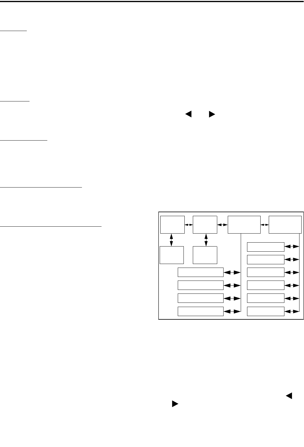
TRANSCEIVER OPERATION
2-21 November 1999
Part No. 001-7780-500
Six Beeps
•The paged radio received the page and acknowl-
edged it (Section 2.5.7).
•The message that was sent has been received and
acknowledged (Section 2.5.8).
•The status condition that was sent has been received
and acknowledged (Section 2.5.9).
Two Beeps
•The emergency alarm condition was acknowledged
(Section 2.5.10).
Gurgle-Like Tone
•Dynamic regrouping has occurred (Section 2.5.13).
•Dynamic regrouping has occurred but the
regrouping channel is not selected (Section 2.5.13).
Four Low Tones (Busy Signal)
•The radio system is busy or a busy condition exists
when making a telephone call.
Four Alternating High and Low Tones
•A channel is available after a busy condition
occurred (SMARTNET/SmartZone only).
2.7 KEYPAD PROGRAMMING
2.7.1 INTRODUCTION
NOTE: Keypad programming is available with full
keypad (15-key) models only.
Keypad programming is available if the Keypad
Programming option switch is programmed. It is then
selected by simply pressing this switch (no password
is required). Keypad programming allows conven-
tional channel parameters such as the transmit and
receive frequency and Call Guard squelch code to be
changed. In addition, it allows several conventional
mode timers to be changed. It cannot be used to repro-
gram disabled channels or SMARTNET/SmartZone
channels.
2.7.2 MENU DESCRIPTION
A menu is used to select parameters to be
changed in the keypad programming mode. When the
Keypad Programming mode is selected by pressing the
option switch, the “P”and“
G” icons are displayed
(see Figure 2-3) along with the first menu parameter
“ZONE CHG”.
The four main menu parameters are listed below,
and descriptions are located in the indicated section.
Press the and keys to display the desired
parameter and then press the ENT key to select it.
Pressing the CLR key in any of the four main menus
exits the keypad programming mode. Pressing it in the
other menus returns to the previous menu. A flowchart
showing the keypad programming mode menu struc-
ture is located in Figure 2-4.
•ZONE CHG (2.7.3)
•CHAN CHG (2.7.4)
•SYS PRM (2.7.5)
•CHAN PRM (2.7.6)
Figure 2-4 Keypad Programming Menu
Flowchart
2.7.3 ZONE CHANGE PARAMETER
The “ZONE CHG” menu parameter selects the
zone containing the conventional channel to be repro-
grammed. It does not change the zone selected for
normal operation. Enter the zone number or scroll
through the programmed zones by pressing the
and keys. When the desired zone is displayed,
select it by pressing the ENT key.
Zone Channel
Change
Change
System
Parameters
Channel
Parameters
Select
Zone
Select
Channel
Scan Hold Timer
Time-Out Timer
Penalty Timer
Conver. Timer
Rx Freq
Tx Freq
Rx CG Code
Tx CG Code
Tx Power
TOT On-Off

TRANSCEIVER OPERATION
2-22
November 1999
Part No. 001-7780-500
2.7.4 CHANNEL CHANGE PARAMETER
The “CHAN CHG” menu parameter selects the
conventional channel to be reprogrammed. Disabled or
SMARTNET/SmartZone channels cannot be selected.
This does not change the channel selected for normal
operation.
Enter the channel number or scroll through the
programmed channels by pressing the and
keys. When the desired channel is displayed, select it
by pressing the ENT key.
2.7.5 SYSTEM PARAMETERS
The “SYS PRM” menu parameter selects the
conventional mode timer to be reprogrammed (see
following). Press the and keys to display the
desired timer and then press the ENT keytoselectit.
SCAN TMR - Selects the Scan Hold timer. Press
the and keys to decrement/increment the
timer in 0.5-second steps, and press the “0” key to
disable the timer (set it to 0 seconds). When the
desired value is displayed, store it by pressing the
ENT key.
TX TMR - Selects the transmit time-out timer.
Press the and keys to decrement/increment
the timer in 15-second steps, and press the “0” key
to disable the timer (set it to 0 seconds). When the
desired value is displayed, press the ENT key to
store it.
PEN TMR - Selects the penalty timer. Press the
and keys to decrement/increment the timer
in 15-second steps, and press the “0” key to disable
the timer (set it to 0 seconds). When the desired
value is displayed, store it by pressing the ENT
key.
CONV TMR - Selects the conversation timer.
Press the and keys to decrement/increment
the timer in 30-second steps, and press the “0” key
to disable the timer (set it to 0 seconds). When the
desired value is displayed, store it by pressing the
ENT key.
2.7.6 CHANNEL PARAMETERS
The “CHAN PRM” menu parameter selects the
conventional channel parameter to be reprogrammed
(see following). Press the and keys to display
the desired parameter and then press the ENT key to
select it.
RX FREQ - Selects the receive channel frequency.
Press the and keys to move the cursor left
and right, and press the 0-9 keys to enter a digit.
When the desired frequency is displayed, store it
by pressing the ENT key.
TX FREQ - Same as RX FREQ above.
RX CODE - Selects the receive Call Guard
(CTCSS/DCS) code. Press the “0” key to display
the first available code, and press it again to toggle
between types (CTCSS and DCS). Press the
and keys to scroll through the available codes.
When the desired code is displayed, store it by
pressing the ENT key.
TX CODE - Same as RX CODE above.
TX POWER - Selects the desired power output
level. Press the and keys to scroll through
the following choices. When the desired setting is
displayed, store it by pressing the ENT key.
•POWER HI - High transmit power
•POWERLO-Lowtransmitpower
•POWER SW - Switchable power selectable by
the High/Low power switch. This choice is not
available if that switch is not programmed.
TX TMR - Enables or disables the time-out timer
on the current channel. Press the and keys
to toggle between the on and off mode, and when
the desired setting is displayed, store it by pressing
the ENT key.
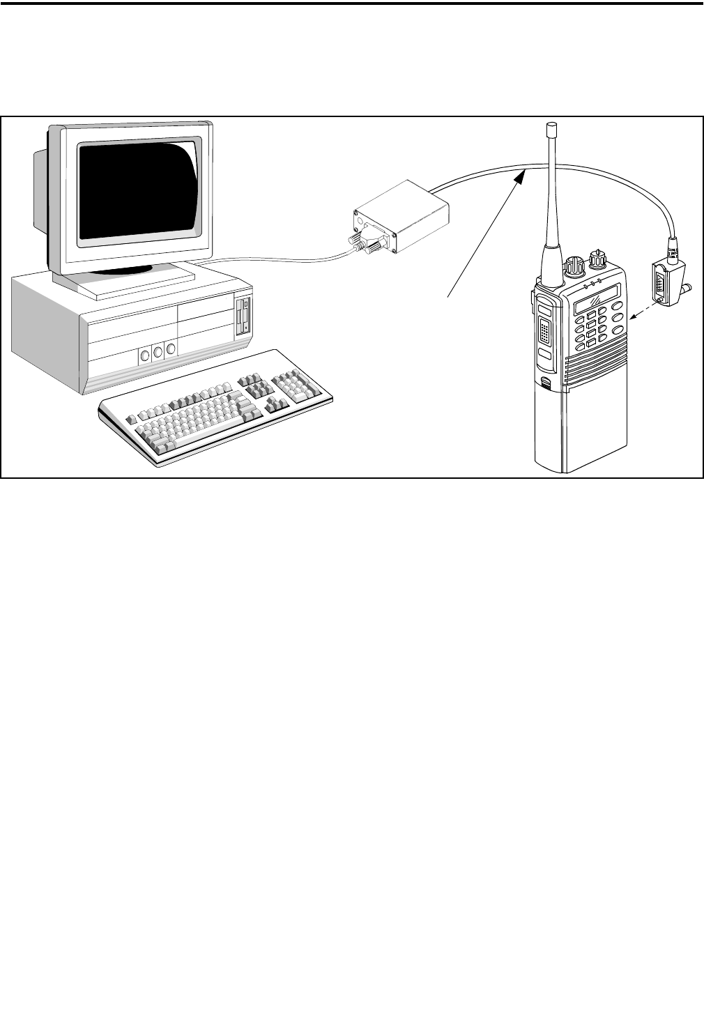
3-1 November 1999
Part No. 001-7780-500
TRANSCEIVER PROGRAMMING
SECTION 3 TRANSCEIVER PROGRAMMING
Figure 3-1 Programming Setup
Remote Programming Interface (RPI)
Part No. 023-9800-000
RPI-Transceiver
Programming Cable
Part No. 597-2002-123
3.1 GENERAL
3.1.1 PROGRAMMING SETUP
The following items are required to program the
transceiver and control unit. The part numbers of this
equipment are shown in Table 1-1 in Section 1. The
programming set-up is shown above.
•IBM® PC or compatible personal computer
•Remote Prog. Interface (RPI) P.N. 023-9800-000
•Cables from the RPI to the computer and
transceiver
•EFJohnson PCTrunk programming software.
3.1.2 COMPUTER DESCRIPTION
The computer used to run this program should
meet the following minimum requirements:
•Windows® 3.1, 95/98, or NT 3.51
•Intel® 486 processor or equivalent
•At least 4 MB of RAM
•A hard disk drive with at least 5 MB of free space
•An available serial port
NOTE: With the descriptions which follow, it is
assumed that you have a basic understanding of how
to use your Windows-based operating system. If you
are not familiar with some of the Windows functions
described, refer to your Help Screens and manuals
included with your Windows software.
3.1.3 PCTRUNK SOFTWARE INSTALLATION
The PCTrunk software is supplied on two 3-1/2”
diskettes. Install this software as follows:
1. Make sure that there are no other Windows applica-
tions open during this installation procedure. Also,
make sure that the computer meets the minimum
requirements listed in the preceding section.
2. Insert PCTrunk Disk 1 in the disk drive of your
computer.
3. Windows 3.1 or NT - In the Program Manager,
double click the SETUP.EXE file on PCTrunk Disk
1 or click this file name and select File > Run.

TRANSCEIVER PROGRAMMING
3-2
November 1999
Part No. 001-7780-500
Windows 95/98 - Select Start > Settings > Control
Panel and double click “Add/Remove Programs”.
Then click Install and Next. When SETUP.EXE is
automatically located on the floppy drive, click
Next, select the location for the start-up icon, and
enter the name you want to call the program.
4. Follow the instructions displayed by the setup
program. The default directory for the program is
\Program Files\PCTrunk. If you wish to use some
other directory, click Browse and select it or type the
name.
3.1.4 CONNECTING RPI TO COMPUTER AND
TRANSCEIVER
RPI Information
The RPI provides the required interface between
the computer and transceiver. It converts the RS-232
logic levels from the computer to the 5V logic levels
required by the transceiver microprocessor and vice
versa.
The current RPI available for programming trans-
ceivers of this type is Part No. 023-9800-000. Earlier
RPI’s, such as 023-9750-000 and 023-5810-000 can
also be used. However, the -9800- RPI is the only one
that has the speaker and microphone audio jacks
required to perform the alignment described in Section
6. In addition, it is the only RPI that can be used to
Flash program the transceiver to update the operating
software.
Cable Information
The cables from the RPI to the computer and
transceiver are not included with the RPI. The -9800-
RPI has a female DB9 connector for the computer
connection. Since most computer serial ports have a
male DB9 or DB25 connector, a male DB9 to female
DB9 or DB25 is usually required. This is a standard
cable available at most computer supply stores. A suit-
able cable is also listed in Table 1-1.
The cable from the RPI to the transceiver
connects from the RPI to the accessory connector of
the transceiver. A schematic diagram of this cable is
shown in Figure 3-2. The -122 version of this cable
can also be used because the extra wire connected to
pin 8 is not required with this radio.
Figure 3-2 RPI -Transceiver Cable Schematic
3.1.5 STARTING AND EXITING
To Start PCTrunk From Windows 3.1
In the Program Manager, open the PCTrunk
group window. Then double-click the PCTrunk icon.
To Start PCTrunk From Windows 95/98
Click the Start button and select the PCTrunk
group. Then double-click the PCTrunk icon.
To Exit PCTrunk:
SelectFile>ExitorpressALT+F4.
3.1.6 PROGRAMMING FILE TYPES
Programming data is stored in a disk file that can
be saved, read, copied, and deleted (see Section 3.3.1).
The file that is stored for each programming session
has the .DAT extension.
3.1.7 HELP FILES
To display help information on the current screen,
clickHelpinthemenubarorpressF1.
3.1.8 SCREEN TYPES
The following types of screens are displayed:
Radio-Wide - These screens program parameters that
are the same for all systems and channels. Separate
screens are displayed for General, Conventional,
SMARTNET/SmartZone, and Portable Options
parameters. Refer to Section 3.4 for more information
on these screens.
Modular
Connector
Orange
Black
Green
Yellow
Blue
White
Brown
Red
Pin A Pin B
PROGRAMMING CABLE
Part No. 597-2002-122/-123
RxD
Gnd
Mic Audio
Reset [1]
PTT
Vcc
Speaker
TxD
9
7
5
3
1
8
6
4
2
4
6
2
8
1
5
9
3
A
1
2
3
4
5
6
B
/Flash
[1] Pin 8 is connected on -123 cable only
To
RPI
To Radio
Accessory
Connector
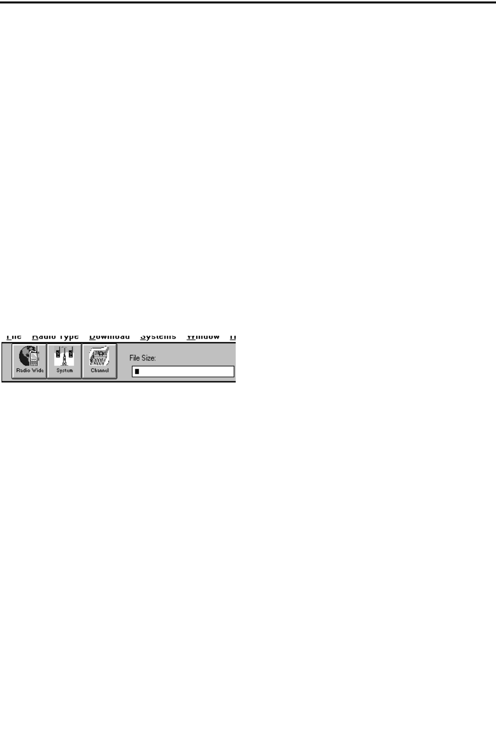
TRANSCEIVER PROGRAMMING
3-3 November 1999
Part No. 001-7780-500
System - These screens program the parameters that
are unique to the displayed Conventional,
SMARTNET, or SmartZone system. The system to be
edited is selected as described in Section 3.1.10.
Channel - This screen programs unique channel
parameters and assigns channels to each zone. The
specific parameters indicated in this screen are deter-
mined by the type of system selected in the “Type”
box (Conventional, SMARTNET, SmartZone).
The preceding screens are displayed in cascade
style or they can be minimized or resized as desired.
To cascade the active screens, select Window >
Cascade from the menu bar (see Section 3.3.6). To pop
a screen to the front, click the applicable button shown
in the following illustration or select it in the Window
menu. For example, if the Channel screen is displayed
and you want to quickly pop the Radio-Wide screen to
the front, click the Radio-Wide button. These buttons
canbedisplayedandhiddenbyclickingWindow>
Toolbar.
Screen Pop-Up Buttons and File Size
Indicator
3.1.9 FILE SIZE INDICATION
The maximum number of channels that can be
programmed may be limited by the available memory
space in the radio as described in Section 1.2.4. A
running indication of the amount of memory used by
the current data if it was downloaded to the radio is
displayed by a bar graph in the toolbar as shown
above. When the bar reaches the right end, the avail-
able memory is full and some channels may need to be
deleted if more information remains to be
programmed.
3.1.10 CREATING AND DISPLAYING
SYSTEMS
To create a new SMARTNET or SmartZone
system, select Systems > Add Systems and then the
desired system type from the menu bar (see Section
3.3.6). This menu is also used to delete a system. Only
one conventional system can be set up, and it is auto-
matically created when a programming file is opened
as described in Section 3.1.6. Therefore, there is no
option to add a conventional system.
Only one system can be displayed at a time.
Therefore, to edit information in one of the systems,
display that system by selecting Window in the menu
bar and then the system to be edited. Systems are iden-
tified by number and type. However, in the Channel
screen, channels or talk groups from any programmed
system can be set up. Therefore, it does not matter
which system is selected when programming channel
information.
3.2 PROGRAMMING PROCEDURE
The following is a general procedure you can use
to program a transceiver.
3.2.1 PRELIMINARY
1. Select a programming file as follows:
Create a New File - To start with a new file
containing default parameters, select File > New
and then the frequency band of the radio (VHF/
UHF/800 MHz).
Open An Existing File - To open an existing file
stored on disk, select File > Open and then the file
to be opened.
Upload a File From a Radio - To transfer a file
from a radio to the computer to edit or use as a
basis to program another radio, connect the radio to
the computer as described in Section 3.1.4. Then
turn the radio on and select Upload from the menu
bar.
2. Before or after creating the programming file, be
sure the correct type (77xx portable) is selected by
the Radio Type menu (see Section 3.3.2).
3. A conventional system is automatically set up when
a new programming file is created. If SMARTNET
or SmartZone systems are also to be programmed,
set up at least one of that type as described in
Section 3.1.10.
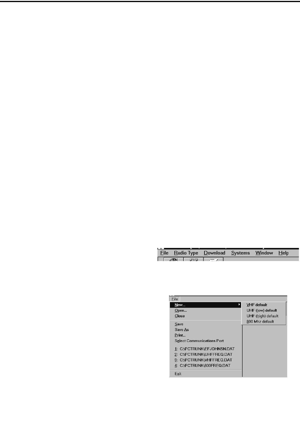
TRANSCEIVER PROGRAMMING
3-4
November 1999
Part No. 001-7780-500
3.2.2 PROGRAMMING RADIO WIDE
PARAMETERS
1. To display the Radio Wide screens, click the Radio
Wide button or select Window > Radio Wide
Parameters in the menu bar (see Section 3.1.8).
2. Program the applicable information in these screens
as described in Section 3.4.
3.2.3 PROGRAMMING CONVENTIONAL
CHANNELS
NOTE: If no conventional channels are programmed,
skip this section.
1. Make sure the conventional system is displayed by
selecting Window > Conventional in the menu bar.
2. If required, display the Conventional System
programming screens by clicking the System button
or selecting Window > Conventional System (see
Section 3.1.8).
3. Program the conventional systems and channels as
described in Section 3.5.
3.2.4 PROGRAMMING SMARTNET AND
SMARTZONE SYSTEMS
NOTE: If no SMARTNET or SmartZone systems are
programmed, skip this section.
1. Make sure the desired SMARTNET or SmartZone
system is displayed by selecting Window >
SMARTNET/SmartZone in the menu bar.
2. If required, display the programming screens for
that system by clicking the System button or
selecting Window > SMARTNET/SmartZone
System (see Section 3.1.8).
3. Program the SMARTNET/SmartZone system and
talk groups as described in Section 3.6.
4. To program additional SMARTNET/SmartZone
systems, add a new system as described in Section
3.1.10 and repeat Section 3.6.
3.2.5 PROGRAMMING RADIO
(DOWNLOADING FILE)
When all the required programming information
has been entered in the various programming screens,
the information can be programmed (downloaded) into
the radio. When downloading a file, be sure that all
connections between the computer and radio are
secure, the radio is turned on, and the proper serial
port is selected (see Section 3.3.1). Then proceed as
follows:
1. Select Download from the menu bar and then the
file type to be transferred (programming or
scrambling).
•If no file is currently loaded, a dialog box appears
to select the desired file.
•If a file is already loaded when Download is
selected, the current file is transferred to the radio.
2. Repeat for the other file type (if required).
NOTE: The information which follows (Sections 3.3-
3.6) provides detailed descriptions of the parameters
that are displayed in the various PCTrunk screens.
3.3 MENU COMMANDS
Menu Bar
3.3.1 FILE MENU
New - Creates a programming file with default param-
eters for the selected frequency range.
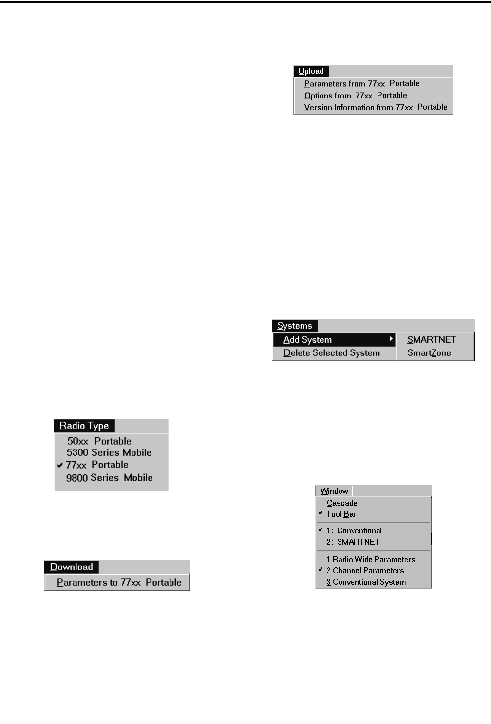
TRANSCEIVER PROGRAMMING
3-5 November 1999
Part No. 001-7780-500
Open - Opens a programming file that was previously
saved to disk. If a modified file is currently open, you
are asked if that file should be saved before the new
file is opened.
Close - Closes the current file. If the file has been
modified and the changes have not been saved, you are
asked if the changes should be saved before closing.
Save - Saves the current file to disk using the current
file name.
Save As - Same as “Save” except you are prompted to
enter a new file name if desired.
Print - Prints the information in the current file.
Select Communications Port - Displays the Commu-
nications Port dialog box which is used to select the
serial port that is used to connect the transceiver to the
computer (see Section 3.1.4).
Exit - Closes the PCTrunk program. If the current file
has been modified and the changes have not been
saved, you are asked if the changes should be saved
before closing.
3.3.2 RADIO TYPE MENU
The Radio Type menu show above selects the
radio type (77xx Portable) being programmed.
3.3.3 DOWNLOAD MENU
Parameterto77xxPortable-Transfers the current
programming file to the radio connected to the
computer.
3.3.4 UPLOAD MENU
The Upload Menu is displayed only in the
opening screen before a programming file is created.
The following options are displayed:
Parameters from 77xx Portable - Transfers the
programming data from a radio to the PCTrunk
program. This data can then be viewed, edited, or
saved to a disk file as desired.
Version Information from 77xx Portable - Displays
the software version number and serial number of the
connected radio.
3.3.5 SYSTEMS MENU
The Systems Menu is used to create new
SMARTNET and SmartZone systems. It is also used
to delete current systems. Conventional systems
cannot be added because only one can be created.
Refer to Section 3.1.8 for more information.
3.3.6 WINDOW MENU
The Window Menu is used to select the system to
be edited. It can also be used to pop one of the screens
to the front. See Section 3.1.8 for more information.
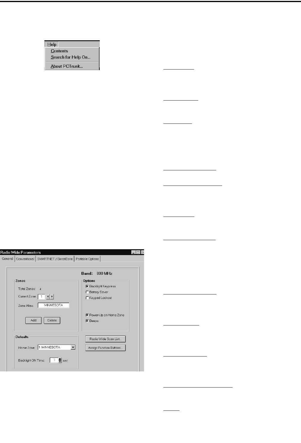
TRANSCEIVER PROGRAMMING
3-6
November 1999
Part No. 001-7780-500
3.3.7 HELP MENU
Contents - Displays the help system table of contents.
Search For Help On - Displays the search dialog box
that allows searching for a help topic by keyword.
About PCTrunk - Displays the software version
number of PCTrunk and the address of the E.F.
Johnson Company.
3.4 RADIO-WIDE PARAMETER SCREENS
3.4.1 INTRODUCTION
The radio-wide screens program the parameters
that are the same for all systems, channels, and zones.
Separate screens are used for General, Conventional,
SMARTNET/SmartZone, and Portable Options
parameters. Refer to the information which follows.
3.4.2 RADIO-WIDE GENERAL SCREEN
Band
Displays the operating band selected by the Radio
Type Menu (see Section 3.3.2). The selected oper-
ating band must match that of the radio being
programmed. Currently, only 800 MHz 77xx models
are available.
Zones
Total Zones - The total number of zones currently set
up. The maximum number allowed is 16. Zones are
added by clicking the Add button (see following).
Current Zone - Indicates the currently selected zone.
To select another zone, click the up/down arrows.
Zone Alias - Edits the unique alpha identification for
the displayed zone.Up to 8 characters can be entered.
The zone alias is briefly displayed whenever a new
zone is selected. Refer to Section 1.2.4 for more
information on zones.
Add (Zones) Button - Adds another zone.
Delete (Zones) Button - Deletes the last zone added.
Defaults
Home Zone - Selects the zone that is selected by the
Home Zone option switch if programmed.
Backlight On Time - Selects the length of time that
the backlight stays on after any key or the Backlight
option switch is pressed (see “Options” which fol-
lows and Section 2.3.3).
Options
Backlight Key Press - If checked, the backlight turns
on for the “Backlight On Time” above whenever any
front panel key is pressed (see Section 2.3.3).
Battery Saver - If checked, low transmit power is
automatically selected when the RSSI level indicates
that the site is nearby (see Section 2.3.6).
Keypad Lockout - If checked, all front panel keys are
disabled and are not available to the user (see Section
2.3.5).
Power-Up On Home Zone - If checked, the home
zone is always selected at power-up.
Beeps - If checked, all tones are enabled. Otherwise,
no tones sound (see Section 2.3.10).
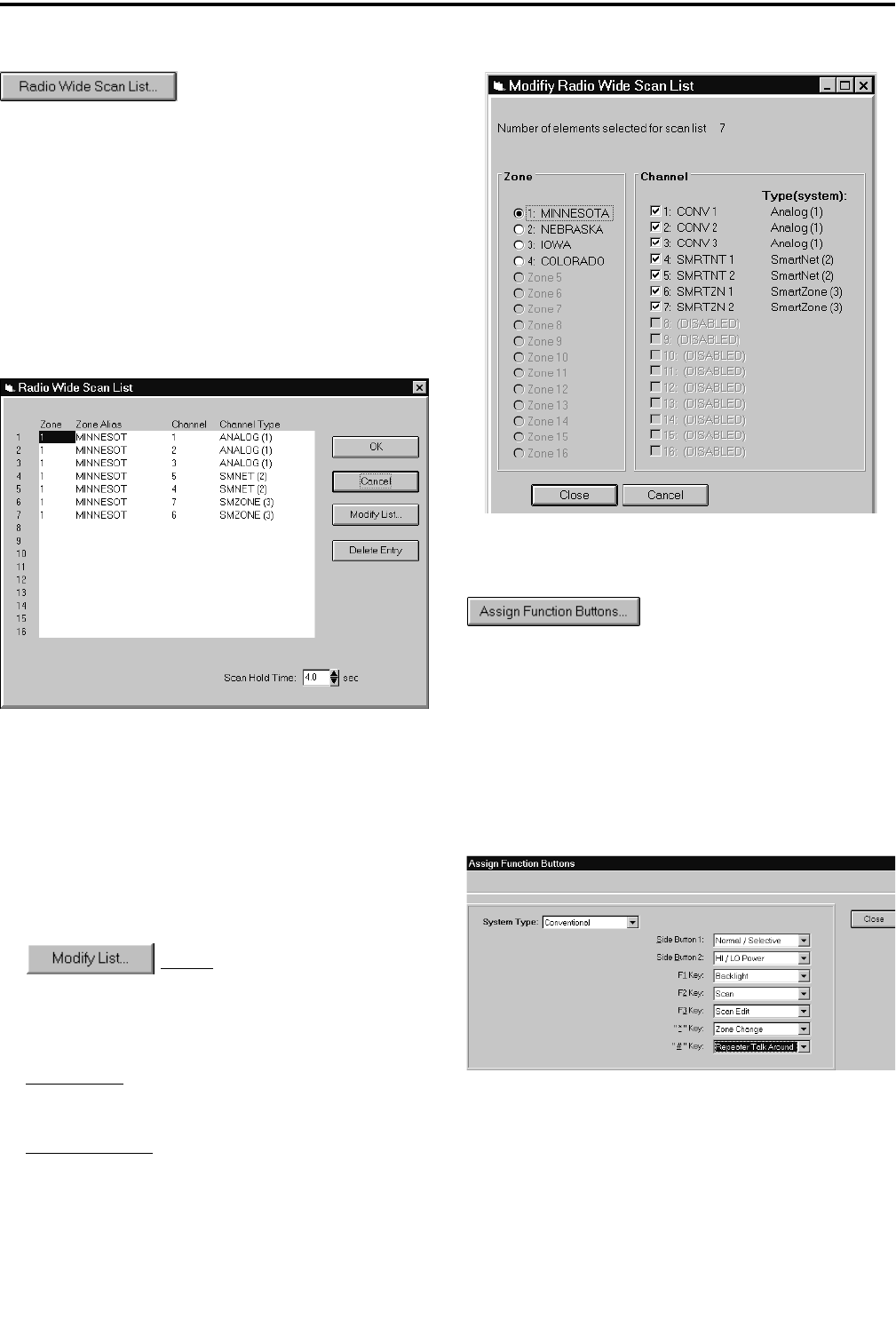
TRANSCEIVER PROGRAMMING
3-7 November 1999
Part No. 001-7780-500
Radio Wide Scan List
NOTE: The radio-wide scan list cannot be pro-
grammed until all channels to be included have been
set up as described in the Conventional and SMART-
NET/SmartZone sections (3.5 and 3.6, respectively).
Clicking the Radio Wide Scan List button in the
General screen displays the following screen which
programs the radio-wide scan list described in Section
2.3.11. The buttons and other parameters in this screen
are as follows:
Radio-Wide Scan List Screen
Button - Displays the following
screen that selects the channels in each Zone and
System that are in this scan list. Select each Zone
and then the channels to be included from that zone.
Delete Entry - Deletes the selected channel from the
scan list.
Scan Hold Time - This programs the delay that
occurs before radio-wide scanning resumes after a
message is no longer being received. Times of 0 -
7.5 seconds can be programmed (see Section
2.3.11).
Modify List Screen
Assign Function Buttons
Clicking the “Assign Functions Buttons” Button
in the General screen displays the following screen
which programs the option switches. Two are located
on the side panel and three or five on the front panel as
described in Section 2.3.4. These option switches can
be programmed with a different set of functions for
each operating mode (conventional and SMARTNET/
SmartZone).
Assign Function Buttons Screen
Program the option switches as follows:
1. In the System Type pull-down menu, select the
mode to be programmed (either conventional or
SMARTNET/SmartZone).
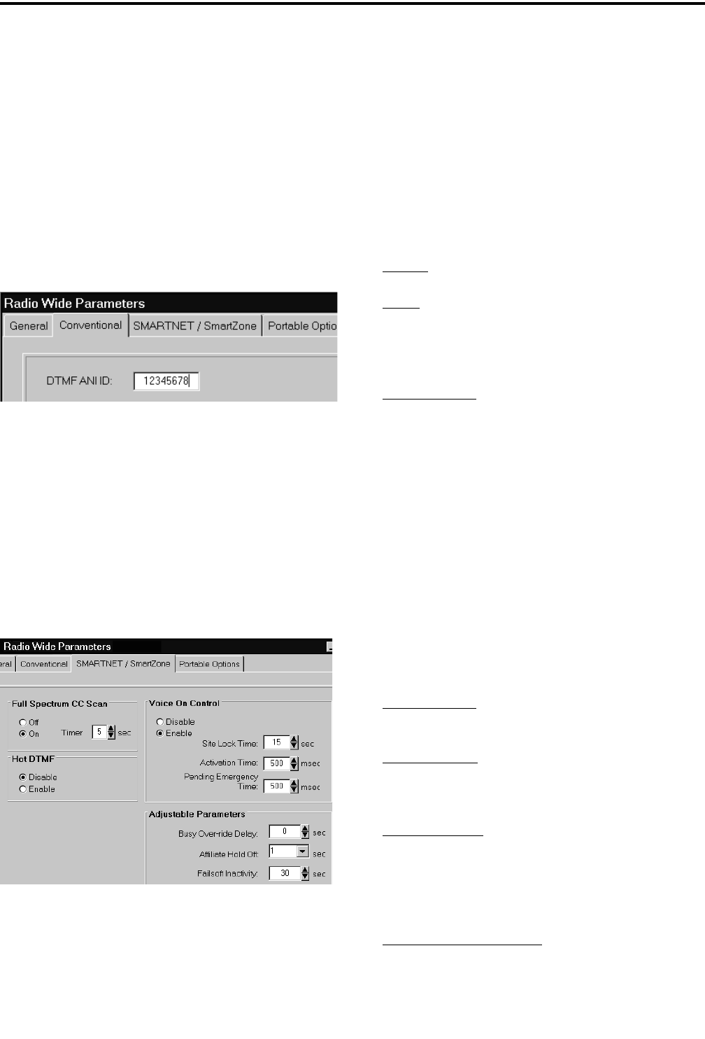
TRANSCEIVER PROGRAMMING
3-8
November 1999
Part No. 001-7780-500
2. To program a switch, click the arrow to display the
pull-down menu and then select the desired function
from that menu. NOTE: Side Button 1 is the top
(AUX) button and Side Button 2 is the bottom (FCN)
button. Also, the * and # keys are not available with
limited keypad (3-key) models.
3. Repeat for all switches and modes to be
programmed and then exit this screen by clicking
the Close button.
3.4.3 RADIO-WIDE CONVENTIONAL SCREEN
The radio-wide conventional screen is shown
above, and it is used to program the DTMF ANI ID.
This ID is used on channels programmed for pre- or
post-transmit ANI (see Section 3.5.4) and consists of
eight digits from 0-9.
3.4.4 RADIO-WIDE SMARTNET/SMARTZONE
SCREEN
The radio-wide SMARTNET/SmartZone screen
is shown above, and is used to program the following
parameters:
Full Spectrum CC Scan
In a SmartZone system, if all potential control
channel frequencies have been searched, the radio
enters a channel-by-channel search across the full
spectrum that the radio covers. The timer sets the time
it performs this scan before it checks the expected
frequencies again. After it checks these frequencies, it
returns to full spectrum scanning. This cycle repeats
until a control channel is found.
On-Off - Enables or disables full spectrum scan.
Timer - Sets the time that full spectrum scanning
occurs as just described.
Hot DTMF
Enable/Disable - When enabled, allows the user to
send DTMF tones while transmitting. When dis-
abled, pressing numeric keys (0-9, , #) while
transmitting has no affect.
Voice On Control
With SmartZone operation, some remote sites are
designated Voice On Control sites. In these sites, if all
available traffic channels are occupied, control chan-
nels become traffic channels when additional traffic
channels are requested. The Voice On Control parame-
ters determine how the radio reacts to various situa-
tions that may occur. For example, when a conversa-
tion is complete, the radio may look for a control
channel that has become a traffic channel.
Enable/Disable - Determines if the voice on control
parameters are active.
Site Lock Time - This is the amount of time a radio
remains on the Voice On Control site before looking
for another site.
Activation Time - This is the amount of time the
radio waits when the control channel comes back
from Voice On Control before it transmits any pend-
ing ISWs. This prevents all radios on a Voice On
Control site from submitting ISWs at the same time.
Pending Emergency Time - This is the amount of
time the radio waits to submit an Emergency ISW
*
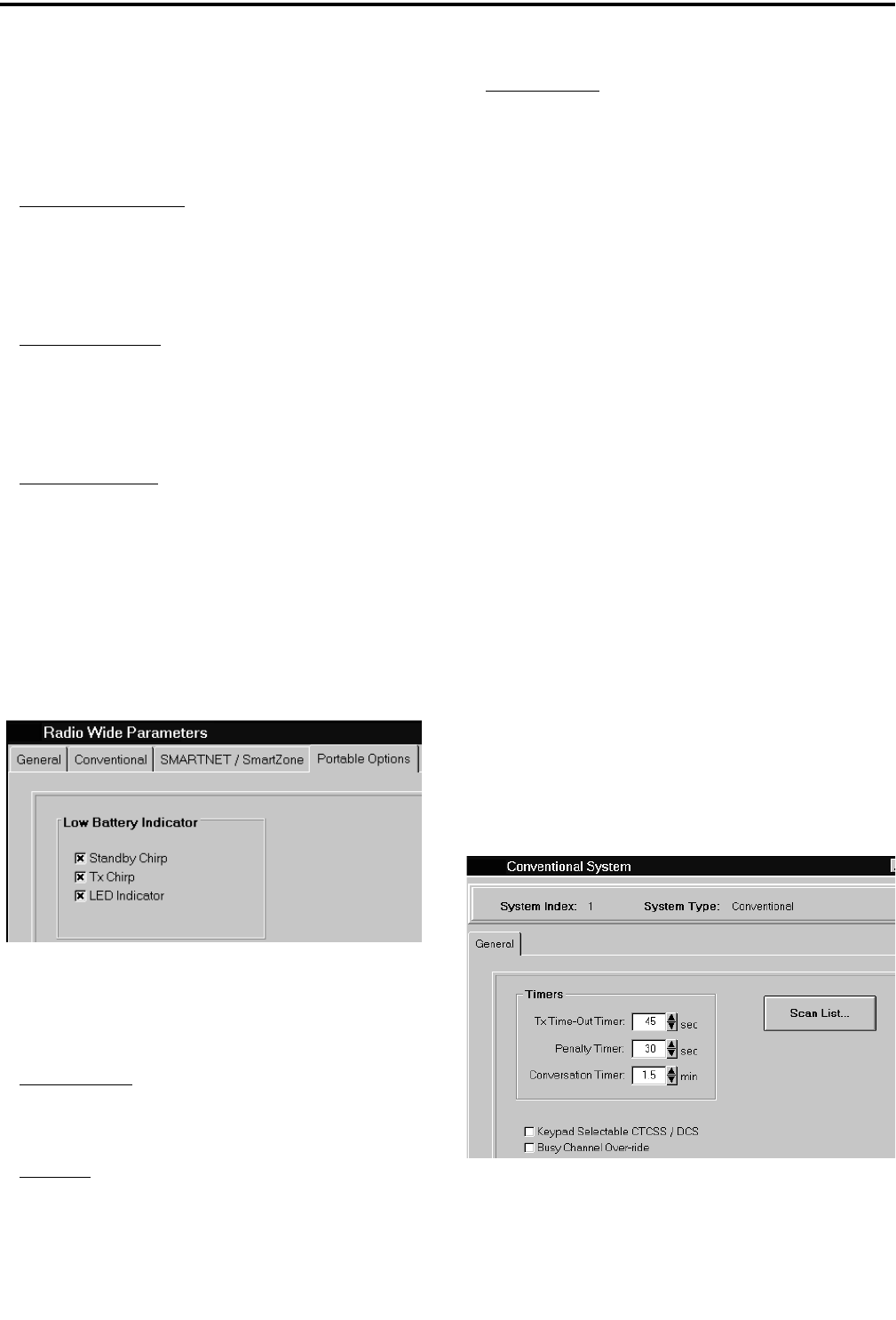
TRANSCEIVER PROGRAMMING
3-9 November 1999
Part No. 001-7780-500
after the control channel returns from the Voice On
Control mode.
Adjustable Parameters
Busy Override Delay - With SmartZone operation,
this is the amount of time a user must press the PTT
switch to override a SmartZone busy that occurs
because some member of the talk group is present at
a site where there are no traffic channels available.
Affiliate Hold Off - With SmartZone operation, this
is the delay time that occurs after acquiring the con-
trol channel before it sends an affiliation ISW. This
prevents all radios on the system from sending affil-
iation ISWs at the same time.
Failsoft Inactivity - Programs failsoft operation (see
Section 2.5.11). If the radio remains inactive (no
receive or transmit activity on channel) while operat-
ing in the failsoft mode for the programmed time, the
radio momentarily leaves the failsoft mode and
attempts to find a control channel. If “0” is pro-
grammed, the radio does not leave the failsoft mode.
3.4.5 RADIO-WIDE PORTABLE OPTIONS
SCREEN
The radio-wide Mobile Options screen is shown
above, and is used to program the following
parameters (see Section 2.3.6):
Standby Chirp - Selects if a beep sounds every
minute while a low battery condition is being
detected.
Tx Chirp - Selects if a beep sounds every time the
PTT switch is pressed while a low battery condition
is being detected.
LED Indicator - Selects if the top panel BAT LED
indicates a low battery condition.
3.5 PROGRAMMING CONVENTIONAL
SYSTEMS AND CHANNELS
3.5.1 INTRODUCTION
The following information describes how
conventional channels are programmed. Conventional
systems do not need to be set up because only one can
be programmed, and it is automatically set up when
the programming file is selected as described in
Section 3.1.6. Up to 256 conventional channels can be
programmed (if no SMARTNET/SmartZone systems
are programmed). Refer to Section 1.2.4 for more
information on systems and channels.
The following is the recommended procedure for
programming conventional channels:
1. Program the radio-wide information as described in
Section 3.4.
2. If other types of systems are programmed, make
sure the conventional system is selected by selecting
Window > Conventional in the menu bar.
3. Program the conventional system information and
then the channel information as follows.
3.5.2 CONVENTIONAL SYSTEM GENERAL
SCREEN
The conventional system General screen is shown
above, and it programs the following parameters:
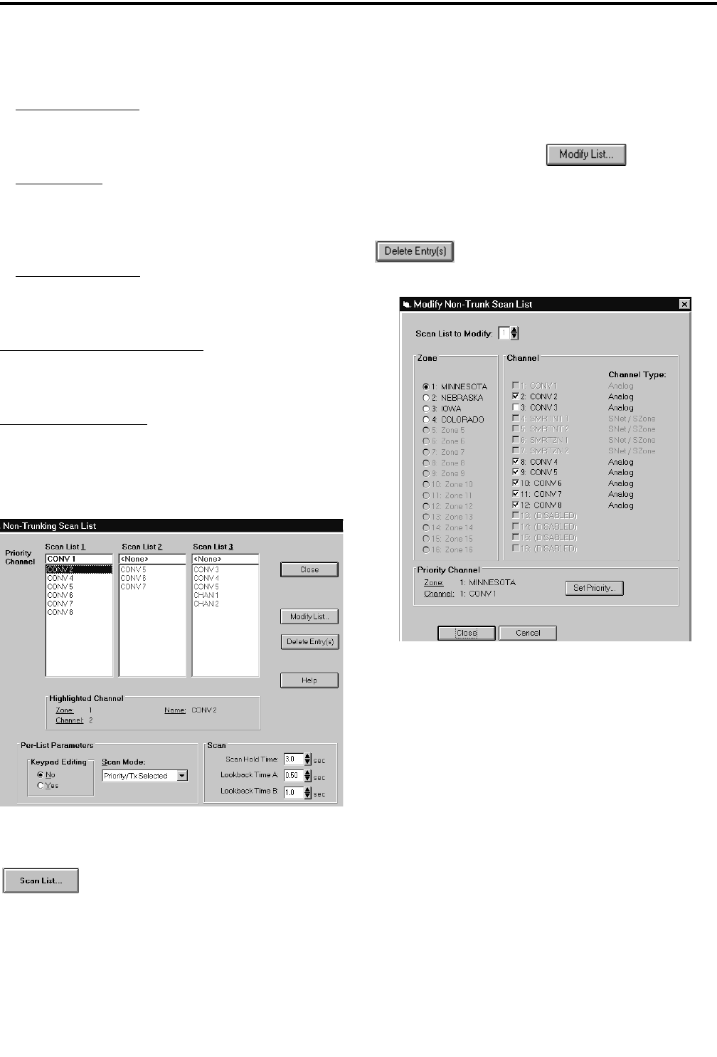
TRANSCEIVER PROGRAMMING
3-10
November 1999
Part No. 001-7780-500
Timers
Tx Time-Out Timer - This timer limits the length of
transmissions (Section 2.3.9). Times up to 3 minutes,
45 seconds in 15-second steps can be programmed.
Penalty Timer - This timer disables transmitting after
the time-out timer expires (Section 2.4.7). Times up
to 3 minutes, 45 seconds in 15-second steps can be
programmed.
Conversation Timer - This timer limits the total
length of a conversation (Section 2.4.8). Times up to
7.5 minutes in 0.5-minute steps can be programmed.
Keypad Selectable CTCSS/DCS - Selects if CTCSS/
DCS (Call Guard) squelch codes can be reassigned
using the keypad (see Section 2.4.6).
Busy Channel Override - Selects if the busy channel
lockout feature can be overridden by quickly releasing
and then pressing the PTT switch (see Section 2.4.5).
Conventional System Scan List Screen
Scan List Button
Clicking the Scan List button displays the
preceding screen which is used to program the conven-
tional scan lists described in Section 2.4.11. Only Scan
List 1 is available with limited keypad (3-key) models.
NOTE: The conventional scan lists cannot be
programmed until all the conventional channels are
programmed. Therefore, first program the channels as
described in Sections 3.5.3 and 3.5.4.
To modify a list, click and the
screen which follows is displayed. Select the desired
scan list in the box on the top and then select the zone
and the channels from that zone to be included. Repeat
for each zone. Do this for each list programmed. The
button deletes the selected channel(s)
from the scan list.
Conventional System Modify Scan List Screen
The following parameters are programmed in the
Conventional System Scan List Screen on the left.
Keypad Editing
This function selects if the user is allowed to edit
the scan list. This requires the Scan Edit option switch
as described in Section 2.4.11. User editing can be
enabled and disabled on each scan list.
Scan Mode
Sets the channel on which transmissions occur
when the PTT switch is pressed while scanning. A
different mode can be programmed for each scan list.
In addition, it selects if priority sampling is used and

TRANSCEIVER PROGRAMMING
3-11 November 1999
Part No. 001-7780-500
also the type of priority channel (see the “Priority
Channel” description which follows). The following
modes are available:
No Priority - Priority sampling does not occur (all
channels are scanned in sequence). The radio trans-
mits on the selected channel.
Priority/Tx Priority - Priority sampling occurs
and the priority channel is the one programmed in
the selected scan list. The radio transmits on the
priority channel.
Priority/Tx Selected - Priority sampling occurs
and the priority channel is the one programmed in
the selected scan list. The radio transmits on the
selected channel.
Priority on Sel Chan - The priority channel is
always the selected channel (even if the scan list is
programmed with a priority channel). The radio
transmits on the selected channel.
Talkback Scan - No priority sampling occurs
(even if the scan list is programmed with a priority
channel). The radio transmits on the channel of a
call while scanning is halted. Then when scanning
resumes, it transmits on the selected channel.
Scan Timers
Scan Hold Time - Sets the delay that occurs before
scanning resumes after a signal is no longer
received (see Section 2.3.11).
Lookback Time A - This time determines how
often the priority channel is checked for activity.
Times of 0.25-4.00 seconds in 0.25-second steps
can be programmed.
Lookback Time B - This time determines how
often the priority channel is checked once an incor-
rect Call Guard (CTCSS/DCS) code is detected.
Since it takes much longer to detect an incorrect
Call Guard signal than a carrier, this time should be
relatively long to prevent the interruptions from
making a message difficult to understand. Times of
0.5-8.0secondscanbeprogrammedin0.5-second
steps.
Priority Channel Selection
The Scan Mode parameter in the preceding
Conventional System Scan List screen selects if
priority channel sampling is enabled on the selected
scan list. It also selects the type of priority channel
(either fixed or the selected) if applicable.
If the “Priority/Tx Priority” or “Priority/Selected”
mode is programmed, fixed priority channel sampling
is selected. The fixed priority channel must then be
chosen for the scan list. To do this, click the
button in the preceding Modify Scan List
screen and then select the desired zone/channel. Refer
to Section 2.4.12 for more information on priority
channel sampling.
3.5.3 SETTING UP CONVENTIONAL
CHANNELS
The conventional Channel screen shown in
Figure 3-3 which follows is displayed when a conven-
tional channel is selected. This screen programs
unique channel parameters and also assigns channels
to the selectable zones displayed by the transceiver.
The general procedure for setting up a conven-
tional channel is as follows. Refer to the descriptions
which follow this procedure for information on the
parameters in the channel screens.
1. Make sure that the desired zone is selected in the
Zone box.
2. Select the channel number in the Channels Index
box which is to be programmed with the channel. If
the channel number display mode is selected (see
Section 2.4.2), this will be the number displayed
when the channel is selected.
3. To assign a conventional channel, select “Conven-
tional” as the channel type.
4. Click the Modify button to display the screen which
enables that channel and programs the alias (tag)
and transmit and receive frequencies. Then program
the other parameters in the main part of the screen.
Refer to the next section for more information.
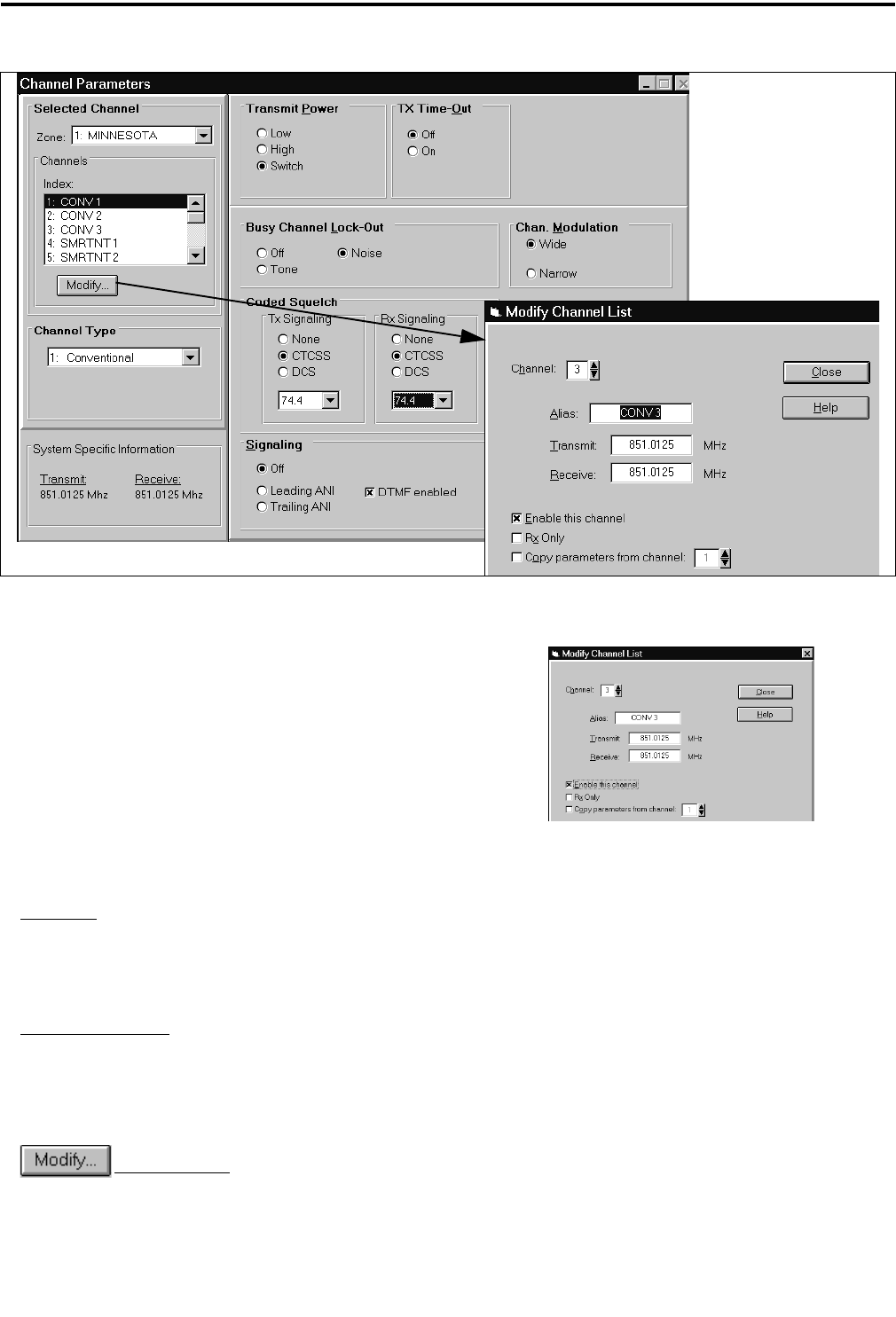
TRANSCEIVER PROGRAMMING
3-12
November 1999
Part No. 001-7780-500
Figure 3-3 Conventional Channel Screen
3.5.4 CONVENTIONAL CHANNEL SCREEN
PARAMETERS
The following parameters are programmed in the
conventional channel screen shown in Figure 3-3.
Selected Channel
Zone Box - Clicking the arrow to the right of this box
displays the available zones. Click on a zone to select
it. Zones and zone aliases are set up on the Radio-
Wide General screen described in Section 3.4.2.
Channel Index Box - Displays the available channels
in the selected zone. The channel type is selected by
the Channel Type box below it.
Modify Button - Displays the screen that
follows which enables the channel (makes it select-
able) and programs the alias (tag) and transmit and
receive frequencies.
The parameters in this screen are as follows:
Channel - Selects the channel to be edited.
Alias - Programs the identification that is displayed
when the channel is selected. Up to 8
characters can be programmed.
Transmit - Programs the transmit frequency of the
channel.
Receive - Programs the receive frequency of the
channel.
Enable This Channel - The box must be checked for
the channel to be selectable.
Rx Only - The box is checked if the channel is
receive-only (transmitter disabled).
Copy Parameters From Channel - If another channel
is selected, the parameters from that chan-
nel are copied to the new channel.

TRANSCEIVER PROGRAMMING
3-13 November 1999
Part No. 001-7780-500
NOTE: Channel numbers not assigned must be
programmed for conventional operation and then not
enabled in the above screen because SMARTNET/
SmartZone channels cannot be disabled.
Channel Type
Channel Type Box - Selects the specific system from
which the channel is selected. All programmed sys-
tems are displayed by number and type (conven-
tional, SMARTNET, SmartZone). When a different
channel type is selected, the screen for that type of
channel is automatically displayed.
System Specific Information - With conventional
systems, indicates the frequency of the selected
channel without having to select the Modify box.
Transmit Power
Fixes the transmit power on the channel for the
high or low level or allows it to be switch selectable
(the Hi/Lo Power option switch is then required).
Refer to Section 2.4.10 for more information.
Tx Time-Out
Enables or disables the time-out timer on the
channel. The time-out timer time is programmed in the
conventional system General screen (Section 3.5.2).
Busy Channel Lockout
Off = disabled, Noise = transmit disallowed if
carrier is detected, Tone = transmit allowed with
carrier detected only if correct Call Guard (CTCSS/
DCS)codeisdetected.
Coded Squelch
This sets the transmit and receive Call Guard
(CTCSS/DCS) coding, if any, used on the channel. If
“None” is selected, no code is transmitted and carrier-
controlled squelch is used when receiving (Section
2.4.6). The standard Call Guard tones and codes are
listed in Table 3-1 on page 3-22.
Signaling
Off - No ANI signaling is used.
Leading ANI - A DTMF-coded ID is sent at the
beginning of each transmission. This ID is set in the
radio-wide conventional screen (Section 3.4.3).
Trailing ANI - A DTMF-coded ID is sent at the end
of each transmission.
DTMF Enabled - With full keypad (15-key) models,
allows manual dialing of numbers using the DTMF
keypad.
Channel Modulation
This selects if the channel modulation is wide-
band (5 kHz) or narrowband (2.5 kHz).
3.6 PROGRAMMING SMARTNET/SMARTZONE
SYSTEMS AND CHANNELS
3.6.1 INTRODUCTION
To program SMARTNET and SmartZone
systems and channels, proceed as follows:
1. Program the SMARTNET/SmartZone radio-wide
information as described in Section 3.4.
2. To create a new SMARTNET/SmartZone system,
select the Systems > Add Systems in the menu bar
(see Section 3.1.10). Up to sixteen systems of any
type can be programmed as described in Section
1.2.4.
3. Program the SMARTNET/SmartZone system infor-
mation as described starting in the next section.
Make sure the desired SMARTNET or SmartZone
system is displayed by selecting it in the Window
menu in the menu bar. Then program the channels as
described starting in Section 3.6.8.
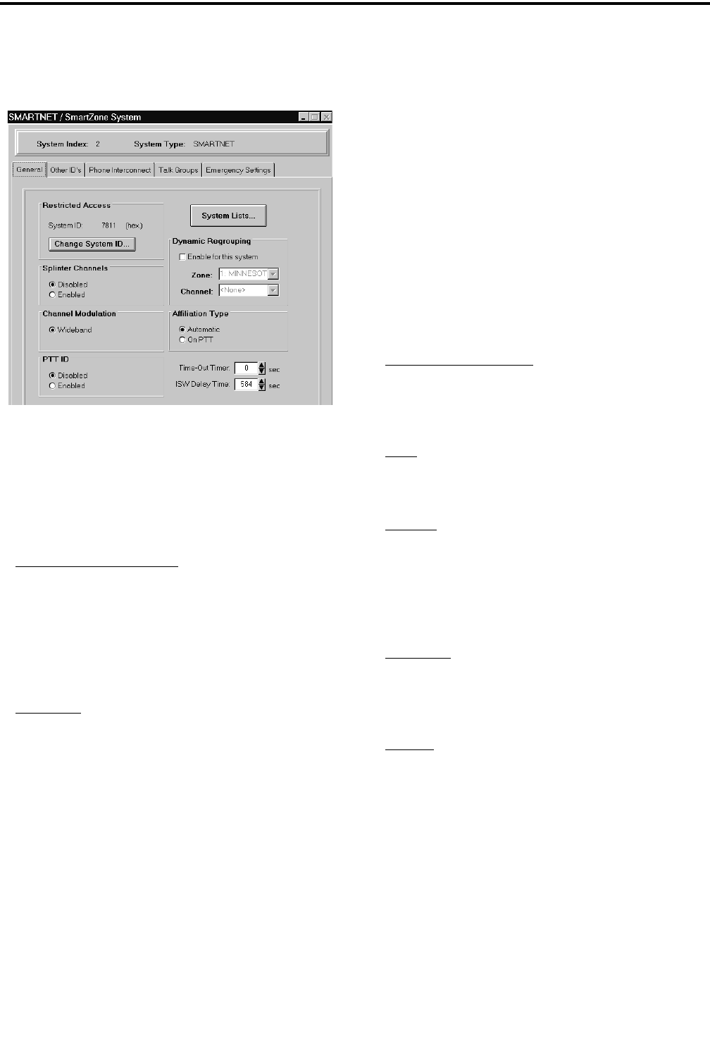
TRANSCEIVER PROGRAMMING
3-14
November 1999
Part No. 001-7780-500
3.6.2 SMARTNET/SMARTZONE SYSTEM
GENERAL SCREEN
The SMARTNET/SmartZone System General
screen is shown above, and it programs the following
parameters:
Restricted Access
Change System ID Button - Displays the Change
System ID screen which is used to enter the system
ID of the system. This ID is entered as a hexadecimal
number from 0-9 and A-F. Valid numbers are from
0001-FFFF. The system ID corresponding to the
desired ID must also be located in the “key” subdi-
rectory of the program file.
System ID - Read-only field which shows the ID of
the system currently being edited.
Splinter Channels
When splinter channels are enabled, the receive
and transmit frequencies are 12.5 kHz lower than the
normal frequencies. Splinter channels are used only as
required in the Mexico and Canada border areas for
frequencies between 806 and 820.975 MHz.
Channel Modulation
When “Wideband” is enabled, the radio operates
with a 4 kHz maximum deviation between 821.000
and 824.975 MHz and 5 kHz maximum deviation for
all other frequencies. When it is disabled, deviation is
5 kHz with all frequencies.
PTT ID
Enables or disables the PTT ID.
System Lists Button
This button displays the screens used to program
the various lists that are unique for each SMARTNET/
SmartZone system. Refer to Section 3.6.7 for more
information on these lists.
Dynamic Regrouping
Enable For This System - When this box is checked,
a dynamic regrouping channel is enabled. This is a
SMARTNET channel which has the corresponding
talk group dynamically set by the dispatcher.
Zone - The physical zone containing the dynamic
regrouping channel. The value is selected on the
Channel Parameters screen.
Channel - The physical channel used for dynamic
regrouping. The value is selected on the Channel
Parameters screen.
Affiliation Type
Automatic - The radio immediately affiliates with the
central controller as soon as it is turned on and auto-
matically re-affiliates each time the talk group is
changed.
On PTT - The radio affiliates with the central control-
ler only when the PTT switch is pressed.
Time-Out Timer
Programs the time-out timer setting for the
system. It can be programmed for 0 min, 15 sec up to
3 min, 45 sec or it can be disabled (see Section 2.3.9).
ISW Delay Time
Increasing or decreasing this value changes the
transmission timing of ISWs relative to the reception
of OSWs.
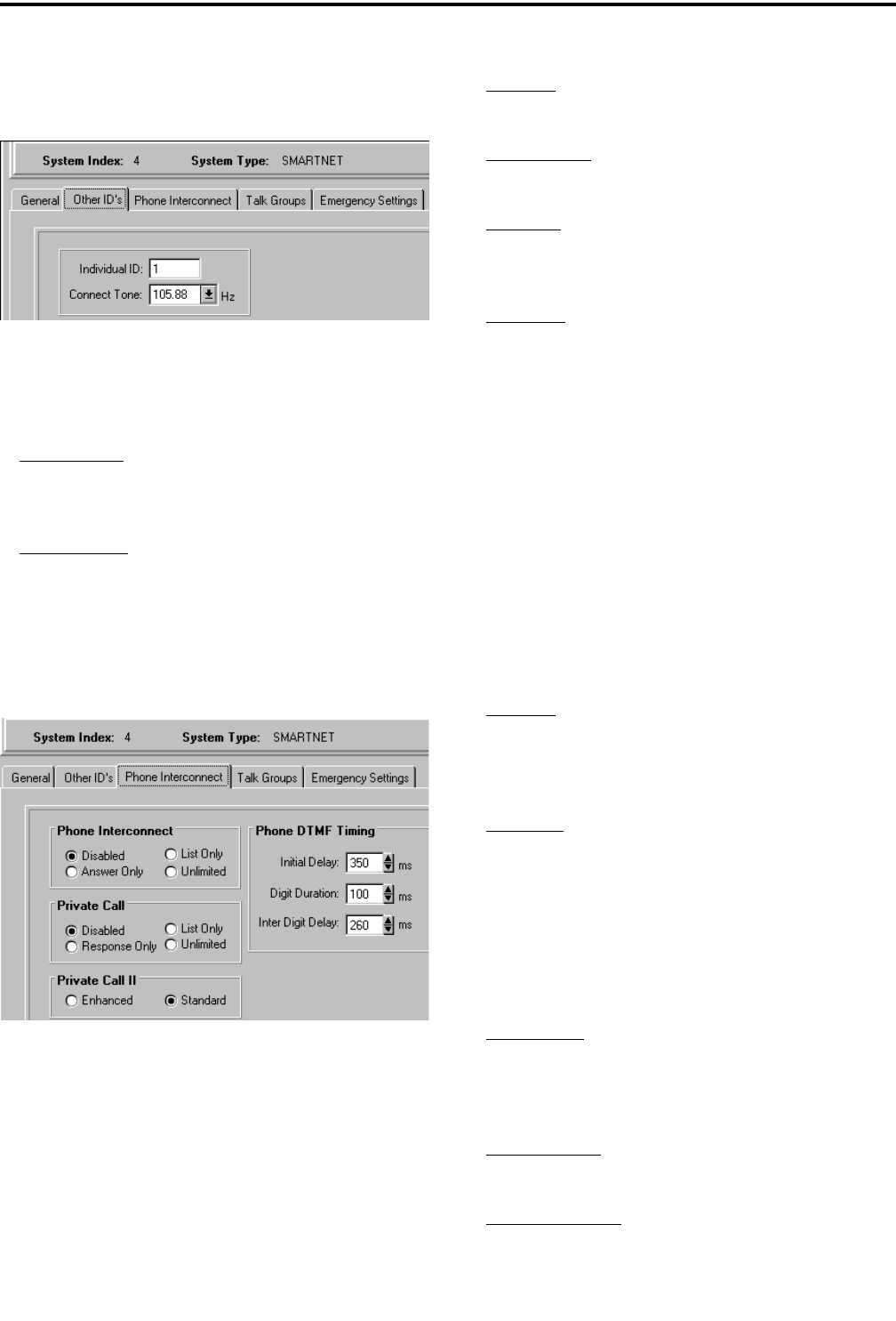
TRANSCEIVER PROGRAMMING
3-15 November 1999
Part No. 001-7780-500
3.6.3 SMARTNET/SMARTZONE SYSTEM
OTHER ID’S SCREEN
The SMARTNET/SmartZone Other ID’s screen
is shown above, and it programs the following
parameters.
Individual ID - Uniquely identifies the radio on a par-
ticular system. Each radio must have a different Unit
ID. Valid Unit IDs are from 1-49152.
Connect Tone - The tone expected by the controller
on the traffic channel to verify that a subscriber trans-
mission is occurring. This tone should be set the
same as it is in the controller.
3.6.4 SMARTNET/SMARTZONE SYSTEM
PHONE INTERCONNECT SCREEN
The SMARTNET/SmartZone Phone Intercon-
nect screen is shown above, and the parameters it
programs are as follows:
Phone Interconnect
Refer to Section 2.5.6 for more information on
telephone calls.
Disabled - Telephone calls cannot be placed or
received.
Answer Only - Telephone calls can be received but
not placed.
List Only - Telephone calls can be placed and
received, and numbers can be recalled from memory
only.
Unlimited - Telephone calls can be placed and
received, and numbers can be recalled from memory
or dialed using the front panel keypad (full keypad
15-key models only).
Private Call
Same as above, but for private (unit-to-unit) calls.
Refer to Sections 2.5.4 and 2.5.5 for more information.
Private Call II
Programs either standard (Private Conversation
II™) or enhanced (Enhanced Private Conversation™)
private calls as follows:
Standard - The user does not receive any feedback
when the called radio is not active in the system.
Only a “No Answer” is received if the called radio
does not answer.
Enhanced - When a call is placed, the system tells the
user if the called radio is currently active in the sys-
tem and within range. Thecalling radio displays “NO
ACK” if the called radio is not active in the system
and “NO ANSWR” if it is active but does not answer.
Phone DTMF Timing
Initial Delay - Delay from 50-500 milliseconds from
when a traffic channel is granted for phone intercon-
nect to the start of the dialing out of the phone
number.
Digit Duration - Duration from 50-500 milliseconds
of each phone number digit.
Inter-Digit Delay - Delay from 50-500 milliseconds
between each digit of a phone number.
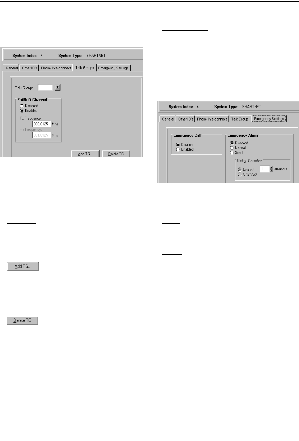
TRANSCEIVER PROGRAMMING
3-16
November 1999
Part No. 001-7780-500
3.6.5 SMARTNET/SMARTZONE SYSTEM
TALK GROUPS SCREEN
The SMARTNET/SmartZone Talk Groups screen
is used to set up SMARTNET/SmartZone talk groups
and program unique talk group information. This
screen is shown above, and the parameters it programs
are as follows:
Talk Group - Selects the talk group to program. This
is the actual ID of the talk group. Talk groups are
added or deleted by clicking the Add TG or Delete
TG button (see following). Talk groups are assigned
to channels on the channel screen (see Section 3.6.9).
- Clicking this button displays a dialog
box that adds a new talk group. The alias (alphatag)
of up to 8 characters is entered, and the new group is
then added after the others that are already set up.
Each SMARTNET/SmartZone system can be pro-
grammed with up to 256 talk groups.
- Clicking this button deletes the cur-
rently selected talk group (the one displayed in the
“Talk Group” box).
Failsoft Channel
Enable - Enables a failsoft channel on the talk group
if a controller failure occurs (see Section 2.5.11).
Disable - The failsoft mode is not entered if the
controller fails.
Tx/Rx Frequency - Programs the failsoft channel
frequency if “Enabled” is checked.
3.6.6 SMARTNET/SMARTZONE SYSTEM
EMERGENCY SETTINGS SCREEN
The SMARTNET/SmartZone Emergency
Settings screen and the parameters it programs are as
follows:
Emergency Call
Enable - When the Emergency option switch and
then the PTT switch are pressed, an emergency group
call is transmitted.
Disable - An emergency group call is not authorized.
Emergency Alarm
Disabled -No emergency signal is sent when the user
presses the Emergency option switch.
Normal - When the user presses the Emergency
option switch, an emergency signal is sent to the dis-
patcher. Audio and visual feedback is provided by
the radio.
Silent - Same as “Normal” except no audio or visual
feedback is provided.
Retry Counter - When “Unlimited” is selected, an
emergency call is repeated until acknowledged or
canceled. When “Limited” is checked, calls are
attempted only the specified number of times.
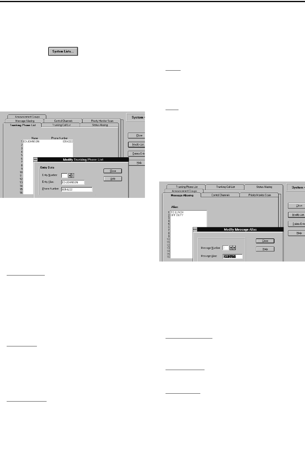
TRANSCEIVER PROGRAMMING
3-17 November 1999
Part No. 001-7780-500
3.6.7 SMARTNET/SMARTZONE SYSTEM
LISTS SCREENS
Clicking the button in the General
screen described in Section 3.6.2 displays the screens
used to program the various lists that are unique for
each SMARTNET/SmartZone system. These screens
are as follows:
Trunking Phone List Screen
This screen programs the phone number list if
used (see Section 2.5.6). To edit this list, click the
Trunking Phone List tab and then the “Modify List”
button on the right side of the screen. The following
information is then programmed in the dialog box that
is displayed:
Entry Number - This box selects the entry to be
edited. The scroll bars to the right of this box select
the desired entry. A phone list can contain up to 16
entries. Selecting a new entry number automatically
validates and stores the current entry. If the current
entry contains an invalid field (for example, too
many digits in the phone number), the entry number
does not change and the invalid field is highlighted.
Entry Alias - Up to 8 characters can be entered to
identify the phone number. This identification is dis-
played when phone numbers are selected by the user
from the list. Only uppercase letters can be entered,
so lowercase letters are automatically converted to
uppercase by the program.
Phone Number - This is the number dialed when the
location is selected. Characters that can be entered
include 0-9, #, (,), and P (a “P” programs a pause).
The maximum number of digits excluding (,) and
spaces is 16, and the maximum including (,) and
spacesis24.
Close - Clicking this button verifies the current entry,
stores it, and then closes the dialog box. If the current
entry contains an invalid field, the dialog box does
not close and the invalid field is highlighted.
Help - Accesses the Help screen. Help can also be
selected at any time by pressing the F1 key.
Message Aliasing Screen
This screen associates an alias (name) with each
message number (see Section 2.5.8). To edit this list,
click the Message Aliasing tab and then the “Modify
List” button on the right side. The following informa-
tion is then programmed in the dialog box that is
displayed:
Message Number - This box selects the message to
be edited. The scroll bars to the right of this box
select the desired message number.
Message Alias - Programs the alias which can be up
to any 8 alphanumeric characters.
Close Button - Validates the entry and closes the dia-
log box. The entry is also validated when another
message number is selected.

TRANSCEIVER PROGRAMMING
3-18
November 1999
Part No. 001-7780-500
Announcement Groups Screen
This screen programs the announcement groups
that are used to communicate with several talk groups
simultaneously. There can be up to 3 announcement
groups per system, and each announcement group can
have up to 15 talk groups.
To create an announcement group, click the “Add
AG” button and the “Add TGs to the AG” screen
shown above is displayed. Enter the announcement
group ID, click the talk groups to select/de-select those
that are to be included, and then create the announce-
ment group by clicking the “Create AG” button. To
delete the current announcement group, click the
“Delete AG” button.
To edit an announcement group, click the
“Modify List” button on the right and the preceding
screen is displayed. Select the announcement group to
be edited from a pull-down menu selecting by clicking
the “AG” arrow. Then click the talk groups to select/
de-select them and then click the “Update List” button
to make the changes.
Control Channels Screen
This screen allows the system manager to view
and edit the control channels. Each SMARTNET
system can have up to four control channels, and each
SmartZone system can have up to 32 control channels.
Only one control channel is active at a time.
To edit this list, click the Control Channels tab
and then the “Modify List” button on the right side.
The following information is then programmed in the
dialog box that is displayed:
Control Channel - Selects the control channel to be
edited. To add a new channel, click the “New Entry”
button.
Frequency - The transmit and receive frequency of
the control channel. These are the mobile frequen-
cies, not the repeater frequencies. Only multiples of
5kHzand6.25kHzarevalid.With800MHzfre-
quencies, a receive frequency 45 MHz above the
transmit frequency is automatically entered.
New Entry Button - Click this button to display the
dialog box used to add another control channel.
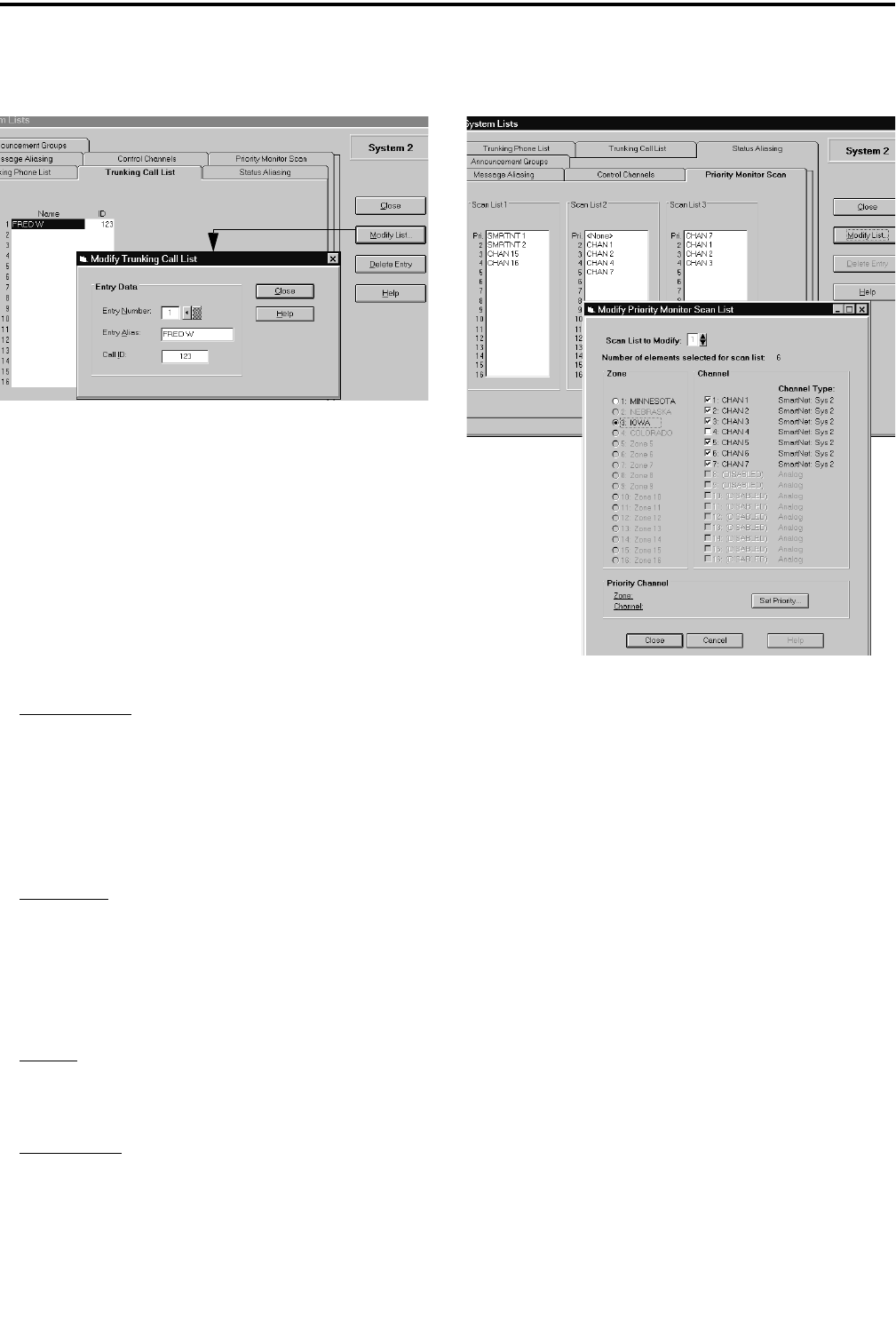
TRANSCEIVER PROGRAMMING
3-19 November 1999
Part No. 001-7780-500
Trunking Call List Screen
This screen is shown above, and it allows the list
of IDs used for private calls to be programmed. A
maximum of 16 IDs can be programmed (see Sections
2.5.4 and 2.5.5).
To edit this list, click the Trunking Call List tab
and then the “Modify List” button on the right side.
This following information is then programmed in the
dialog box that is displayed:
Entry Number - This box selects the entry to be
edited. The scroll bars to the right of this box select
the desired entry. A private call list can contain up to
16 entries. Selecting a new entry number automati-
cally validates and stores the current entry. If the cur-
rent entry contains an invalid field, the entry number
does not change and the invalid field is highlighted.
Entry Alias - Up to 8 characters can be entered to
identify the user being called. This identification is
displayed when the mobile to be called is selected by
the user from the list. Only uppercase letters can be
entered, so lowercase letters are automatically con-
verted to uppercase by the program.
Call ID - This is the ID of the radio being called.
Valid entries are 1-65535. A “0” is detected as no
entry.
Close Button - Verifies the current entry, stores it,
and then closes the dialog box. If the current entry
contains an invalid field, the dialog box does not
close and the invalid field is highlighted.
Priority Monitor Scan Screen
This screen programs up to three Priority Monitor
scan lists that are allowed. Each scan list can contain
up to 15 channels plus a priority channel (see Section
2.5.12). These channels must be from the same
SMARTNET/SmartZone system. Channels set up for
other systems are not allowed.
To edit a list, click the Priority Monitor Scan tab
and then click the “Modify List” button on the right
side. A screen similar to the bottom screen shown
above is then displayed to select the channels to be
included in that scan list. Select channels as follows:
1. Selectthescanlisttobeeditedbyclickingthescroll
bars next to the “Scan List To Modify” box.
2. Select the first zone with channels to be included
and select the desired channels. Repeat for the other
zones.
3. To select the priority channel, click the Set Priority
button. Then select the desired Zone/Channel or
“None” if no priority channel is to be scanned.
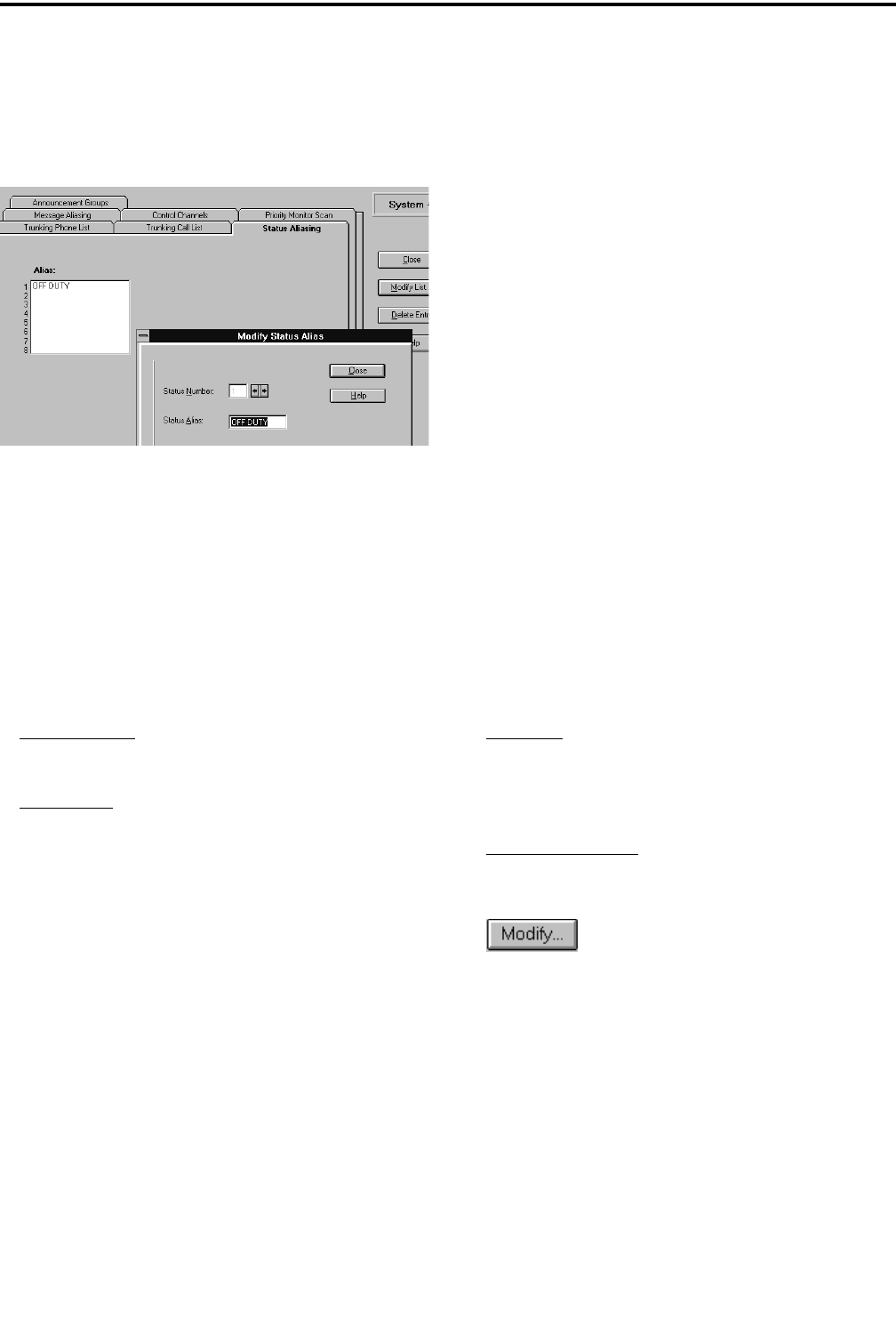
TRANSCEIVER PROGRAMMING
3-20
November 1999
Part No. 001-7780-500
4. Repeat the preceding steps for the other scan lists if
applicable.
Status Aliasing Screen
This screen is shown above, and it programs the
alias for each of up to eight status conditions that can
be sent. The meaning of each status number is defined
by the system manager. Refer to Section 2.5.9 for
more information.
To edit this list, click the Status Aliasing tab and
then the “Modify List” button on the right side. The
following information is then programmed in the
dialog box that is displayed:
Status Number -Thescrollbarstotherightofthis
box select the status number that is to be edited.
Status Alias - Programs up to 8 characters that iden-
tify the status. This identification is displayed when
the user selects a status condition.
3.6.8 SETTING UP SMARTNET/SMART-
ZONE CHANNELS
The SMARTNET/SmartZone Channel screen
shown in Figure 3-4 is displayed when the
SMARTNET or SmartZone channel type is selected.
This screen programs unique channel parameters and
also assigns channels to the selectable zones displayed
by the transceiver.
The general procedure for setting up a
SMARTNET/SmartZone channel is as follows. Refer
to the descriptions which follow this procedure for
information on SMARTNET/SmartZone Channel
screen parameters.
1. Make sure that the desired zone is selected in the
Zone box.
2. Select the channel number in the Channels Index
box which is to be programmed with the channel.
3. To set up a SMARTNET channel, select
“SMARTNET” as the channel type, and to set up a
SmartZone channel, select “SmartZone”.
4. Click the Modify button to display the dialog box
shown in the lower part of Figure 3-4. This box
programs the alias (tag) that is displayed when it is
selected.
5. Program the other parameters in the main part of the
screen (see information which follows).
3.6.9 SMARTNET/SMARTZONE CHANNEL
SCREEN PARAMETERS
The following parameters are programmed in the
SMARTNET/SmartZone channel screen shown in
Figure 3-4.
Selected Channel
Zone Box - Clicking the arrow to the right of this box
displays the available zones. Click on a zone to select
it. Zones and zone aliases are set up on the Radio-
Wide General screen described in Section 3.4.2.
Channel Index Box - Displays the channels in the
selected zone. The channel type is selected by the
Channel Type box below it.
- Displays the screen shown in the lower
part of Figure 3-4. The parameters programmed in
this screen are as follows:
Channel - Selects the channel to be edited.
Alias - Programs the identification that is displayed
when the channel is selected. Up to 8
characters can be programmed.
Transmit - Not programmable because the transmit
frequency is dynamically assigned over the
air (“Trunked” is always displayed).
Receive - Dynamically assigned like the transmit
frequency.

TRANSCEIVER PROGRAMMING
3-21 November 1999
Part No. 001-7780-500
Figure 3-4 SMARTNET/SmartZone Channel Screen
Enable This Channel - Not used because SMART-
NET/SmartZone channels are always
enabled if set up. To disable a channel so
that it is not selectable, choose the conven-
tional type and do not check this box.
Copy Parameters From Channel - If another channel
is selected in the box, the parameters from
that channel are copied to the new channel.
Channel Type
Channel Type Box - Selects the specific system from
which the channel is selected. All programmed
systems are displayed by number and type (conven-
tional, SMARTNET, SmartZone). When a different
channel type is selected, the screen for that type of
channel is automatically displayed.
Other Screen Parameters
System Specific Information - With SMARTNET/
SmartZone systems, indicates the system ID
programmed on the system General screen (see
Section 3.6.2).
Talk Group - Selects the talk group selected by that
channel. Talk groups are programmed in the Talk
Group screen described in Section 3.6.5.
Announcement Group - Selects one of up to three
announcement groups selected by the channel. Refer
to “Announcement Group Screen” in Section 3.6.7
for more information.
Emergency Group - Selects the talk group used for
emergency calls.

TRANSCEIVER PROGRAMMING
3-22
November 1999
Part No. 001-7780-500
Talk Permit Tone - When enabled, a short tone
sounds after a request for a group call has been
approved by the main controller. This indicates that
speaking can begin. When disabled, no audio feed-
back is used to indicate when speaking can begin.
System Scan - Selects the Priority Monitor Scan list
selected by the channel (see “Priority Monitor Scan
Screen” description in Section 3.6.7). If “No Scan
List” is programmed, scanning is not selectable on
that channel.
Auto Scan - When enabled and a channel is selected,
the radio automatically begins scanning the scan list
associated with that channel. When disabled, scan-
ning can only be started manually by the Scan option
switch.
Table 3-1 Call Guard (CTCSS/DCS) Codes and Tones
Recommended Tone Call Guard Codes
Code Freq Code Freq Code Freq Code Freq Code Freq
01 67.0 10 94.8 19 127.3 28 173.8 38* 250.3
02 71.9 11** 97.4 20 131.8 29 179.9 39** 69.3
03 74.4 12 100.0 21 136.5 30 186.2 40** 206.5
04 77.0 13 103.5 22 141.3 31 192.8 41** 229.1
05 79.7 14 107.2 23 146.2 32 203.5 42** 254.1
06 82.5 15 110.9 24 151.4 33 210.7
07 85.4 16 114.8 25 156.7 34* 218.1
08 88.5 17 118.8 26 162.2 35* 225.7
09 91.5 18 123.0 27 167.9 37* 241.8
* These tones normally are not used because of their close proximity to the voice frequencies
** This tone is normally not used because it may cause interference with adjacent tones.
Recommended Digital Call Guard Codes
023 065 131 172 261 346 431 532 654 743
025 071 132 174 263 351 432 546 662 754
026 072 134 205 265 364 445 565 664
031 073 143 223 271 365 464 606 703
032 074 152 226 306 371 465 612 712
043 114 155 243 311 411 466 624 723
047 115 156 244 315 412 503 627 731
051 116 162 245 331 413 506 631 732
054 125 165 251 343 423 516 632 734
1 851.0125 806.0125
2 851.0375 806.0375
3 851.0625 806.0625
4 851.0875 806.0875
5 851.1125 806.1125
6 851.1375 806.1375
7 851.1625 806.1625
8 851.1875 806.1875
9 851.2125 806.2125
10 851.2375 806.2375
11 851.2625 806.2625
12 851.2875 806.2875
13 851.3125 806.3125
14 851.3375 806.3375
15 851.3625 806.3625
16 851.3875 806.3875
17 851.4125 806.4125
18 851.4375 806.4375
19 851.4625 806.4625
20 851.4875 806.4875
21 851.5125 806.5125
22 851.5375 806.5375
23 851.5625 806.5625
24 851.5875 806.5875
FCCChan.
No. Mobile Rx
Freq. Mobile Tx
Freq FCCChan.
No. Mobile Rx
Freq. Mobile Tx
Freq FCCChan.
No. Mobile Rx
Freq Mobile Tx
Freq
800 MHz Channels

TRANSCEIVER PROGRAMMING
3-23 November 1999
Part No. 001-7780-500
25 851.6125 806.6125
26 851.6375 806.6375
27 851.6625 806.6625
28 851.6875 806.6875
29 851.7125 806.7125
30 851.7375 806.7375
31 851.7625 806.7625
32 851.7875 806.7875
33 851.8125 806.8125
34 851.8375 806.8375
35 851.8625 806.8625
36 851.8875 806.8875
37 851.9125 806.9125
38 851.9375 806.9375
39 851.9625 806.9625
40 851.9875 806.9875
41 852.0125 807.0125
42 852.0375 807.0375
43 852.0625 807.0625
44 852.0875 807.0875
45 852.1125 807.1125
46 852.1375 807.1375
47 852.1625 807.1625
48 852.1875 807.1875
49 852.2125 807.2125
50 852.2375 807.2375
51 852.2625 807.2625
52 852.2875 807.2875
53 852.3125 807.3125
54 852.3375 807.3375
55 852.3625 807.3625
56 852.3875 807.3875
57 852.4125 807.4125
58 852.4375 807.4375
59 852.4625 807.4625
60 852.4875 807.4875
61 852.5125 807.5125
62 852.5375 807.5375
63 852.5625 807.5625
64 852.5875 807.5875
65 852.6125 807.6125
66 852.6375 807.6375
67 852.6625 807.6625
68 852.6875 807.6875
69 852.7125 807.7125
70 852.7375 807.7375
71 852.7625 807.7625
72 852.7875 807.7875
73 852.8125 807.8125
74 852.8375 807.8375
75 852.8625 807.8625
76 852.8875 807.8875
77 852.9125 807.9125
78 852.9375 807.9375
79 852.9625 807.9625
80 852.9875 807.9875
81 853.0125 808.0125
82 853.0375 808.0375
83 853.0625 808.0625
84 853.0875 808.0875
85 853.1125 808.1125
86 853.1375 808.1375
87 853.1625 808.1625
88 853.1875 808.1875
89 853.2125 808.2125
90 853.2375 808.2375
91 853.2625 808.2625
92 853.2875 808.2875
93 853.3125 808.3125
94 853.3375 808.3375
95 853.3625 808.3625
96 853.3875 808.3875
97 853.4125 808.4125
98 853.4375 808.4375
99 853.4625 808.4625
100 853.4875 808.4875
101 853.5125 808.5125
102 853.5375 808.5375
103 853.5625 808.5625
104 853.5875 808.5875
105 853.6125 808.6125
106 853.6375 808.6375
107 853.6625 808.6625
108 853.6875 808.6875
109 853.7125 808.7125
110 853.7375 808.7375
111 853.7625 808.7625
112 853.7875 808.7875
113 853.8125 808.8125
114 853.8375 808.8375
115 853.8625 808.8625
116 853.8875 808.8875
117 853.9125 808.9125
118 853.9375 808.9375
119 853.9625 808.9625
120 853.9875 808.9875
121 854.0125 809.0125
122 854.0375 809.0375
123 854.0625 809.0625
124 854.0875 809.0875
125 854.1125 809.1125
126 854.1375 809.1375
127 854.1625 809.1625
128 854.1875 809.1875
129 854.2125 809.2125
130 854.2375 809.2375
131 854.2625 809.2625
132 854.2875 809.2875
133 854.3125 809.3125
134 854.3375 809.3375
135 854.3625 809.3625
136 854.3875 809.3875
137 854.4125 809.4125
138 854.4375 809.4375
139 854.4625 809.4625
140 854.4875 809.4875
141 854.5125 809.5125
142 854.5375 809.5375
143 854.5625 809.5625
144 854.5875 809.5875
145 854.6125 809.6125
146 854.6375 809.6375
147 854.6625 809.6625
148 854.6875 809.6875
149 854.7125 809.7125
150 854.7375 809.7375
151 854.7625 809.7625
152 854.7875 809.7875
153 854.8125 809.8125
154 854.8375 809.8375
155 854.8625 809.8625
156 854.8875 809.8875
157 854.9125 809.9125
158 854.9375 809.9375
159 854.9625 809.9625
160 854.9875 809.9875
161 855.0125 810.0125
162 855.0375 810.0375
163 855.0625 810.0625
164 855.0875 810.0875
165 855.1125 810.1125
166 855.1375 810.1375
167 855.1625 810.1625
168 855.1875 810.1875
169 855.2125 810.2125
170 855.2375 810.2375
171 855.2625 810.2625
172 855.2875 810.2875
173 855.3125 810.3125
174 855.3375 810.3375
FCCChan.
No. Mobile Rx
Freq. Mobile Tx
Freq FCCChan.
No. Mobile Rx
Freq. Mobile Tx
Freq FCCChan.
No. Mobile Rx
Freq Mobile Tx
Freq
800 MHz Channels

TRANSCEIVER PROGRAMMING
3-24
November 1999
Part No. 001-7780-500
175 855.3625 810.3625
176 855.3875 810.3875
177 855.4125 810.4125
178 855.4375 810.4375
179 855.4625 810.4625
180 855.4875 810.4875
181 855.5125 810.5125
182 855.5375 810.5375
183 855.5625 810.5625
184 855.5875 810.5875
185 855.6125 810.6125
186 855.6375 810.6375
187 855.6625 810.6625
188 855.6875 810.6875
189 855.7125 810.7125
190 855.7375 810.7375
191 855.7625 810.7625
192 855.7875 810.7875
193 855.8125 810.8125
194 855.8375 810.8375
195 855.8625 810.8625
196 855.8875 810.8875
197 855.9125 810.9125
198 855.9375 810.9375
199 855.9625 810.9625
200 855.9875 810.9875
201 856.0125 811.0125
202 856.0375 811.0375
203 856.0625 811.0625
204 856.0875 811.0875
205 856.1125 811.1125
206 856.1375 811.1375
207 856.1625 811.1625
208 856.1875 811.1875
209 856.2125 811.2125
210 856.2375 811.2375
211 856.2625 811.2625
212 856.2875 811.2875
213 856.3125 811.3125
214 856.3375 811.3375
215 856.3625 811.3625
216 856.3875 811.3875
217 856.4125 811.4125
218 856.4375 811.4375
219 856.4625 811.4625
220 856.4875 811.4875
221 856.5125 811.5125
222 856.5375 811.5375
223 856.5625 811.5625
224 856.5875 811.5875
225 856.6125 811.6125
226 856.6375 811.6375
227 856.6625 811.6625
228 856.6875 811.6875
229 856.7125 811.7125
230 856.7375 811.7375
231 856.7625 811.7625
232 856.7875 811.7875
233 856.8125 811.8125
234 856.8375 811.8375
235 856.8625 811.8625
236 856.8875 811.8875
237 856.9125 811.9125
238 856.9375 811.9375
239 856.9625 811.9625
240 856.9875 811.9875
241 857.0125 812.0125
242 857.0375 812.0375
243 857.0625 812.0625
244 857.0875 812.0875
245 857.1125 812.1125
246 857.1375 812.1375
247 857.1625 812.1625
248 857.1875 812.1875
249 857.2125 812.2125
250 857.2375 812.2375
251 857.2625 812.2625
252 857.2875 812.2875
253 857.3125 812.3125
254 857.3375 812.3375
255 857.3625 812.3625
256 857.3875 812.3875
257 857.4125 812.4125
258 857.4375 812.4375
259 857.4625 812.4625
260 857.4875 812.4875
261 857.5125 812.5125
262 857.5375 812.5375
263 857.5625 812.5625
264 857.5875 812.5875
265 857.6125 812.6125
266 857.6375 812.6375
267 857.6625 812.6625
268 857.6875 812.6875
269 857.7125 812.7125
270 857.7375 812.7375
271 857.7625 812.7625
272 857.7875 812.7875
273 857.8125 812.8125
274 857.8375 812.8375
275 857.8625 812.8625
276 857.8875 812.8875
277 857.9125 812.9125
278 857.9375 812.9375
279 857.9625 812.9625
280 857.9875 812.9875
281 858.0125 813.0125
282 858.0375 813.0375
283 858.0625 813.0625
284 858.0875 813.0875
285 858.1125 813.1125
286 858.1375 813.1375
287 858.1625 813.1625
288 858.1875 813.1875
289 858.2125 813.2125
290 858.2375 813.2375
291 858.2625 813.2625
292 858.2875 813.2875
293 858.3125 813.3125
294 858.3375 813.3375
295 858.3625 813.3625
296 858.3875 813.3875
297 858.4125 813.4125
298 858.4375 813.4375
299 858.4625 813.4625
300 858.4875 813.4875
301 858.5125 813.5125
302 858.5375 813.5375
303 858.5625 813.5625
304 858.5875 813.5875
305 858.6125 813.6125
306 858.6375 813.6375
307 858.6625 813.6625
308 858.6875 813.6875
309 858.7125 813.7125
310 858.7375 813.7375
311 858.7625 813.7625
312 858.7875 813.7875
313 858.8125 813.8125
314 858.8375 813.8375
315 858.8625 813.8625
316 858.8875 813.8875
317 858.9125 813.9125
318 858.9375 813.9375
319 858.9625 813.9625
320 858.9875 813.9875
321 859.0125 814.0125
322 859.0375 814.0375
323 859.0625 814.0625
324 859.0875 814.0875
FCCChan.
No. Mobile Rx
Freq. Mobile Tx
Freq FCCChan.
No. Mobile Rx
Freq. Mobile Tx
Freq FCCChan.
No. Mobile Rx
Freq Mobile Tx
Freq
800 MHz Channels

TRANSCEIVER PROGRAMMING
3-25 November 1999
Part No. 001-7780-500
325 859.1125 814.1125
326 859.1375 814.1375
327 859.1625 814.1625
328 859.1875 814.1875
329 859.2125 814.2125
330 859.2375 814.2375
331 859.2625 814.2625
332 859.2875 814.2875
333 859.3125 814.3125
334 859.3375 814.3375
335 859.3625 814.3625
336 859.3875 814.3875
337 859.4125 814.4125
338 859.4375 814.4375
339 859.4625 814.4625
340 859.4875 814.4875
341 859.5125 814.5125
342 859.5375 814.5375
343 859.5625 814.5625
344 859.5875 814.5875
345 859.6125 814.6125
346 859.6375 814.6375
347 859.6625 814.6625
348 859.6875 814.6875
349 859.7125 814.7125
350 859.7375 814.7375
351 859.7625 814.7625
352 859.7875 814.7875
353 859.8125 814.8125
354 859.8375 814.8375
355 859.8625 814.8625
356 859.8875 814.8875
357 859.9125 814.9125
358 859.9375 814.9375
359 859.9625 814.9625
360 859.9875 814.9875
361 860.0125 815.0125
362 860.0375 815.0375
363 860.0625 815.0625
364 860.0875 815.0875
365 860.1125 815.1125
366 860.1375 815.1375
367 860.1625 815.1625
368 860.1875 815.1875
369 860.2125 815.2125
370 860.2375 815.2375
371 860.2625 815.2625
372 860.2875 815.2875
373 860.3125 815.3125
374 860.3375 815.3375
375 860.3625 815.3625
376 860.3875 815.3875
377 860.4125 815.4125
378 860.4375 815.4375
379 860.4625 815.4625
380 860.4875 815.4875
381 860.5125 815.5125
382 860.5375 815.5375
383 860.5625 815.5625
384 860.5875 815.5875
385 860.6125 815.6125
386 860.6375 815.6375
387 860.6625 815.6625
388 860.6875 815.6875
389 860.7125 815.7125
390 860.7375 815.7375
391 860.7625 815.7625
392 860.7875 815.7875
393 860.8125 815.8125
394 860.8375 815.8375
395 860.8625 815.8625
396 860.8875 815.8875
397 860.9125 815.9125
398 860.9375 815.9375
399 860.9625 815.9625
400 860.9875 815.9875
401 861.0125 816.0125
402 861.0375 816.0375
403 861.0625 816.0625
404 861.0875 816.0875
405 861.1125 816.1125
406 861.1375 816.1375
407 861.1625 816.1625
408 861.1875 816.1875
409 861.2125 816.2125
410 861.2375 816.2375
411 861.2625 816.2625
412 861.2875 816.2875
413 861.3125 816.3125
414 861.3375 816.3375
415 861.3625 816.3625
416 861.3875 816.3875
417 861.4125 816.4125
418 861.4375 816.4375
419 861.4625 816.4625
420 861.4875 816.4875
421 861.5125 816.5125
422 861.5375 816.5375
423 861.5625 816.5625
424 861.5875 816.5875
425 861.6125 816.6125
426 861.6375 816.6375
427 861.6625 816.6625
428 861.6875 816.6875
429 861.7125 816.7125
430 861.7375 816.7375
431 861.7625 816.7625
432 861.7875 816.7875
433 861.8125 816.8125
434 861.8375 816.8375
435 861.8625 816.8625
436 861.8875 816.8875
437 861.9125 816.9125
438 861.9375 816.9375
439 861.9625 816.9625
440 861.9875 816.9875
441 862.0125 817.0125
442 862.0375 817.0375
443 862.0625 817.0625
444 862.0875 817.0875
445 862.1125 817.1125
446 862.1375 817.1375
447 862.1625 817.1625
448 862.1875 817.1875
449 862.2125 817.2125
450 862.2375 817.2375
451 862.2625 817.2625
452 862.2875 817.2875
453 862.3125 817.3125
454 862.3375 817.3375
455 862.3625 817.3625
456 862.3875 817.3875
457 862.4125 817.4125
458 862.4375 817.4375
459 862.4625 817.4625
460 862.4875 817.4875
461 862.5125 817.5125
462 862.5375 817.5375
463 862.5625 817.5625
464 862.5875 817.5875
465 862.6125 817.6125
466 862.6375 817.6375
467 862.6625 817.6625
468 862.6875 817.6875
469 862.7125 817.7125
470 862.7375 817.7375
471 862.7625 817.7625
472 862.7875 817.7875
473 862.8125 817.8125
474 862.8375 817.8375
FCCChan.
No. Mobile Rx
Freq. Mobile Tx
Freq FCCChan.
No. Mobile Rx
Freq. Mobile Tx
Freq FCCChan.
No. Mobile Rx
Freq Mobile Tx
Freq
800 MHz Channels

TRANSCEIVER PROGRAMMING
3-26
November 1999
Part No. 001-7780-500
475 862.8625 817.8625
476 862.8875 817.8875
477 862.9125 817.9125
478 862.9375 817.9375
479 862.9625 817.9625
480 862.9875 817.9875
481 863.0125 818.0125
482 863.0375 818.0375
483 863.0625 818.0625
484 863.0875 818.0875
485 863.1125 818.1125
486 863.1375 818.1375
487 863.1625 818.1625
488 863.1875 818.1875
489 863.2125 818.2125
490 863.2375 818.2375
491 863.2625 818.2625
492 863.2875 818.2875
493 863.3125 818.3125
494 863.3375 818.3375
495 863.3625 818.3625
496 863.3875 818.3875
497 863.4125 818.4125
498 863.4375 818.4375
499 863.4625 818.4625
500 863.4875 818.4875
501 863.5125 818.5125
502 863.5375 818.5375
503 863.5625 818.5625
504 863.5875 818.5875
505 863.6125 818.6125
506 863.6375 818.6375
507 863.6625 818.6625
508 863.6875 818.6875
509 863.7125 818.7125
510 863.7375 818.7375
511 863.7625 818.7625
512 863.7875 818.7875
513 863.8125 818.8125
514 863.8375 818.8375
515 863.8625 818.8625
516 863.8875 818.8875
517 863.9125 818.9125
518 863.9375 818.9375
519 863.9625 818.9625
520 863.9875 818.9875
521 864.0125 819.0125
522 864.0375 819.0375
523 864.0625 819.0625
524 864.0875 819.0875
525 864.1125 819.1125
526 864.1375 819.1375
527 864.1625 819.1625
528 864.1875 819.1875
529 864.2125 819.2125
530 864.2375 819.2375
531 864.2625 819.2625
532 864.2875 819.2875
533 864.3125 819.3125
534 864.3375 819.3375
535 864.3625 819.3625
536 864.3875 819.3875
537 864.4125 819.4125
538 864.4375 819.4375
539 864.4625 819.4625
540 864.4875 819.4875
541 864.5125 819.5125
542 864.5375 819.5375
543 864.5625 819.5625
544 864.5875 819.5875
545 864.6125 819.6125
546 864.6375 819.6375
547 864.6625 819.6625
548 864.6875 819.6875
549 864.7125 819.7125
550 864.7375 819.7375
551 864.7625 819.7625
552 864.7875 819.7875
553 864.8125 819.8125
554 864.8375 819.8375
555 864.8625 819.8625
556 864.8875 819.8875
557 864.9125 819.9125
558 864.9375 819.9375
559 864.9625 819.9625
560 864.9875 819.9875
561 865.0125 820.0125
562 865.0375 820.0375
563 865.0625 820.0625
564 865.0875 820.0875
565 865.1125 820.1125
566 865.1375 820.1375
567 865.1625 820.1625
568 865.1875 820.1875
569 865.2125 820.2125
570 865.2375 820.2375
571 865.2625 820.2625
572 865.2875 820.2875
573 865.3125 820.3125
574 865.3375 820.3375
575 865.3625 820.3625
576 865.3875 820.3875
577 865.4125 820.4125
578 865.4375 820.4375
579 865.4625 820.4625
580 865.4875 820.4875
581 865.5125 820.5125
582 865.5375 820.5375
583 865.5625 820.5625
584 865.5875 820.5875
585 865.6125 820.6125
586 865.6375 820.6375
587 865.6625 820.6625
588 865.6875 820.6875
589 865.7125 820.7125
590 865.7375 820.7375
591 865.7625 820.7625
592 865.7875 820.7875
593 865.8125 820.8125
594 865.8375 820.8375
595 865.8625 820.8625
596 865.8875 820.8875
597 865.9125 820.9125
598 865.9375 820.9375
599 865.9625 820.9625
600 865.9875 820.9875
- 866.0000 821.0000
601 866.0125 821.0125
- 866.0250 821.0250
602 866.0375 821.0375
603 866.0500 821.0500
604 866.0625 821.0625
605 866.0750 821.0750
606 866.0875 821.0875
607 866.1000 821.1000
608 866.1125 821.1125
609 866.1250 821.1250
610 866.1375 821.1375
611 866.1500 821.1500
612 866.1625 821.1625
613 866.1750 821.1750
614 866.1875 821.1875
615 866.2000 821.2000
616 866.2125 821.2125
617 866.2250 821.2250
618 866.2375 821.2375
619 866.2500 821.2500
620 866.2625 821.2625
621 866.2750 821.2750
622 866.2875 821.2875
FCCChan.
No. Mobile Rx
Freq. Mobile Tx
Freq FCCChan.
No. Mobile Rx
Freq. Mobile Tx
Freq FCCChan.
No. Mobile Rx
Freq Mobile Tx
Freq
800 MHz Channels

TRANSCEIVER PROGRAMMING
3-27 November 1999
Part No. 001-7780-500
623 866.3000 821.3000
624 866.3125 821.3125
625 866.3250 821.3250
626 866.3375 821.3375
627 866.3500 821.3500
628 866.3625 821.3625
629 866.3750 821.3750
630 866.3875 821.3875
631 866.4000 821.4000
632 866.4125 821.4125
633 866.4250 821.4250
634 866.4375 821.4375
635 866.4500 821.4500
636 866.4625 821.4625
637 866.4750 821.4750
638 866.4875 821.4875
- 866.5000 821.5000
639 866.5125 821.5125
- 866.5250 821.5250
640 866.5375 821.5375
641 866.5500 821.5500
642 866.5625 821.5625
643 866.5750 821.5750
644 866.5875 821.5875
645 866.6000 821.6000
646 866.6125 821.6125
647 866.6250 821.6250
648 866.6375 821.6375
649 866.6500 821.6500
650 866.6625 821.6625
651 866.6750 821.6750
652 866.6875 821.6875
653 866.7000 821.7000
654 866.7125 821.7125
655 866.7250 821.7250
656 866.7375 821.7375
657 866.7500 821.7500
658 866.7625 821.7625
659 866.7750 821.7750
660 866.7875 821.7875
661 866.8000 821.8000
662 866.8125 821.8125
663 866.8250 821.8250
664 866.8375 821.8375
665 866.8500 821.8500
666 866.8625 821.8625
667 866.8750 821.8750
668 866.8875 821.8875
669 866.9000 821.9000
670 866.9125 821.9125
671 866.9250 821.9250
672 866.9375 821.9375
673 866.9500 821.9500
674 866.9625 821.9625
675 866.9750 821.9750
676 866.9875 821.9875
- 867.0000 822.0000
677 867.0125 822.0125
- 867.0250 822.0250
678 867.0375 822.0375
679 867.0500 822.0500
680 867.0625 822.0625
681 867.0750 822.0750
682 867.0875 822.0875
683 867.1000 822.1000
684 867.1125 822.1125
685 867.1250 822.1250
686 867.1375 822.1375
687 867.1500 822.1500
688 867.1625 822.1625
689 867.1750 822.1750
690 867.1875 822.1875
691 867.2000 822.2000
692 867.2125 822.2125
693 867.2250 822.2250
694 867.2375 822.2375
695 867.2500 822.2500
696 867.2625 822.2625
697 867.2750 822.2750
698 867.2875 822.2875
699 867.3000 822.3000
700 867.3125 822.3125
701 867.3250 822.3250
702 867.3375 822.3375
703 867.3500 822.3500
704 867.3625 822.3625
705 867.3750 822.3750
706 867.3875 822.3875
707 867.4000 822.4000
708 867.4125 822.4125
709 867.4250 822.4250
710 867.4375 822.4375
711 867.4500 822.4500
712 867.4625 822.4625
713 867.4750 822.4750
714 867.4875 822.4875
- 867.5000 822.5000
715 867.5125 822.5125
- 867.5250 822.5250
716 867.5375 822.5375
717 867.5500 822.5500
718 867.5625 822.5625
719 867.5750 822.5750
720 867.5875 822.5875
721 867.6000 822.6000
722 867.6125 822.6125
723 867.6250 822.6250
724 867.6375 822.6375
725 867.6500 822.6500
726 867.6625 822.6625
727 867.6750 822.6750
728 867.6875 822.6875
729 867.7000 822.7000
730 867.7125 822.7125
731 867.7250 822.7250
732 867.7375 822.7375
733 867.7500 822.7500
734 867.7625 822.7625
735 867.7750 822.7750
736 867.7875 822.7875
737 867.8000 822.8000
738 867.8125 822.8125
739 867.8250 822.8250
740 867.8375 822.8375
741 867.8500 822.8500
742 867.8625 822.8625
743 867.8750 822.8750
744 867.8875 822.8875
745 867.9000 822.9000
746 867.9125 822.9125
747 867.9250 822.9250
748 867.9375 822.9375
749 867.9500 822.9500
750 867.9625 822.9625
751 867.9750 822.9750
752 867.9875 822.9875
- 868.0000 823.0000
753 868.0125 823.0125
- 868.0250 823.0250
754 868.0375 823.0375
755 868.0500 823.0500
756 868.0625 823.0625
757 868.0750 823.0750
758 868.0875 823.0875
759 868.1000 823.1000
760 868.1125 823.1125
761 868.1250 823.1250
762 868.1375 823.1375
763 868.1500 823.1500
764 868.1625 823.1625
FCCChan.
No. Mobile Rx
Freq. Mobile Tx
Freq FCCChan.
No. Mobile Rx
Freq. Mobile Tx
Freq FCCChan.
No. Mobile Rx
Freq Mobile Tx
Freq
800 MHz Channels

TRANSCEIVER PROGRAMMING
3-28
November 1999
Part No. 001-7780-500
765 868.1750 823.1750
766 868.1875 823.1875
767 868.2000 823.2000
768 868.2125 823.2125
769 868.2250 823.2250
770 868.2375 823.2375
771 868.2500 823.2500
772 868.2625 823.2625
773 868.2750 823.2750
774 868.2875 823.2875
775 868.3000 823.3000
776 868.3125 823.3125
777 868.3250 823.3250
778 868.3375 823.3375
779 868.3500 823.3500
780 868.3625 823.3625
781 868.3750 823.3750
782 868.3875 823.3875
783 868.4000 823.4000
784 868.4125 823.4125
785 868.4250 823.4250
786 868.4375 823.4375
787 868.4500 823.4500
788 868.4625 823.4625
789 868.4750 823.4750
790 868.4875 823.4875
791 868.5000 823.5000
792 868.5125 823.5125
793 868.5250 823.5250
794 868.5375 823.5375
795 868.5500 823.5500
796 868.5625 823.5625
797 868.5750 823.5750
798 868.5875 823.5875
799 868.6000 823.6000
800 868.6125 823.6125
801 868.6250 823.6250
802 868.6375 823.6375
803 868.6500 823.6500
804 868.6625 823.6625
805 868.6750 823.6750
806 868.6875 823.6875
807 868.7000 823.7000
808 868.7125 823.7125
809 868.7250 823.7250
810 868.7375 823.7375
811 868.7500 823.7500
812 868.7625 823.7625
813 868.7750 823.7750
814 868.7875 823.7875
815 868.8000 823.8000
816 868.8125 823.8125
817 868.8250 823.8250
818 868.8375 823.8375
819 868.8500 823.8500
820 868.8625 823.8625
821 868.8750 823.8750
822 868.8875 823.8875
823 868.9000 823.9000
824 868.9125 823.9125
825 868.9250 823.9250
826 868.9375 823.9375
827 868.9500 823.9500
828 868.9625 823.9625
829 868.9750 823.9750
830 868.9875 823.9875
- 869.0000 824.0000
- 869.0125 824.0125
- 869.0250 824.0250
- 869.0375 824.0375
- 869.0500 824.0500
- 869.0625 824.0625
- 869.0750 824.0750
- 869.0875 824.0875
- 869.1000 824.1000
- 869.1125 824.1125
- 869.1250 824.1250
- 869.1375 824.1375
- 869.1500 824.1500
- 869.1625 824.1625
- 869.1750 824.1750
- 869.1875 824.1875
- 869.2000 824.2000
- 869.2125 824.2125
- 869.2250 824.2250
- 869.2375 824.2375
- 869.2500 824.2500
- 869.2625 824.2625
- 869.2750 824.2750
- 869.2875 824.2875
- 869.3000 824.3000
- 869.3125 824.3125
- 869.3250 824.3250
- 869.3375 824.3375
- 869.3500 824.3500
- 869.3625 824.3625
- 869.3750 824.3750
- 869.3875 824.3875
- 869.4000 824.4000
- 869.4125 824.4125
- 869.4250 824.4250
- 869.4375 824.4375
- 869.4500 824.4500
- 869.4625 824.4625
- 869.4750 824.4750
- 869.4875 824.4875
- 869.5000 824.5000
- 869.5125 824.5125
- 869.5250 824.5250
- 869.5375 824.5375
- 869.5500 824.5500
- 869.5625 824.5625
- 869.5750 824.5750
- 869.5875 824.5875
- 869.6000 824.6000
- 869.6125 824.6125
- 869.6250 824.6250
- 869.6375 824.6375
- 869.6500 824.6500
- 869.6625 824.6625
- 869.6750 824.6750
- 869.6875 824.6875
- 869.7000 824.7000
- 869.7125 824.7125
- 869.7250 824.7250
- 869.7375 824.7375
- 869.7500 824.7500
- 869.7625 824.7625
- 869.7750 824.7750
- 869.7875 824.7875
- 869.8000 824.8000
- 869.8125 824.8125
- 869.8250 824.8250
- 869.8375 824.8375
- 869.8500 824.8500
- 869.8625 824.8625
- 869.8750 824.8750
- 869.8875 824.8875
- 869.9000 824.9000
- 869.9125 824.9125
- 869.9250 824.9250
- 869.9375 824.9375
- 869.9500 824.9500
- 869.9625 824.9625
- 869.9750 824.9750
- 869.9875 824.9875
FCCChan.
No. Mobile Rx
Freq. Mobile Tx
Freq FCCChan.
No. Mobile Rx
Freq. Mobile Tx
Freq FCCChan.
No. Mobile Rx
Freq Mobile Tx
Freq
800 MHz Channels

4-1 November 1999
Part No. 001-7780-500
CIRCUIT DESCRIPTION
SECTION 4 CIRCUIT DESCRIPTION
127($EORFNGLDJUDPRIWKH5)DQGORJLFXQLWVLV
ORFDWHGRQSDJH
4.1 POWER SWITCHING AND REGULATION
4.1.1 POWER SWITCHING
8QVZLWFKHGEDWWHU\YROWDJHLVDSSOLHGWRWKH
SRZHUDPSOLILHUPRGXOHDQGSRZHUFRQWUROFLUFXLWLQ
WKH5)XQLW2WKHUZLVHDOOSRZHULVVZLWFKHGE\
3FKDQQHO026)(7V4DQG4LQWKHORJLF
XQLW7KH/9&&VXSSO\LVSURGXFHGE\4DQGWKH
9&&VXSSO\LVSURGXFHGE\4:KHQWKHRQRII
VZLWFKLVWXUQHGRQWKHRXWSXWRIVZLWFKLQJWUDQVLVWRU
4JRHVORZZKLFKWXUQV4DQG4RQ7KLV
DSSOLHVVZLWFKHGYROWVWRYROWUHJXODWRUV,&
DQG,&WKHDXGLRDPSOLILHUVWDJHVDQGRWKHUSDUWV
RIWKHWUDQVFHLYHU
:KHQWKHSRZHUVZLWFKLVWXUQHGRIIWKHEDVHRI
4LVSXOOHGORZE\5ZKLFKWXUQV4RIIDQG
WKHFROOHFWRUJRHVKLJK+RZHYHUEHFDXVHRIGLRGH
'4DQG4GRQRWWXUQRIIXQWLO&
FKDUJHVWKURXJK57KLVSURYLGHVDVOLJKWWXUQRII
GHOD\WRJLYHWKHPLFURSURFHVVRUWLPHWRWDNHRYHU
SRZHURIIFRQWURO7KHPLFURSURFHVVRULPPHGLDWHO\
GHWHFWVSRZHUWXUQRIIE\PRQLWRULQJWKH2))5(4,
VLJQDORQSLQ,WWKHQFKDQJHVWKH2))5(4RXWSXW
RQSLQWRDKLJKOHYHOZKLFKWXUQV4DJDLQRQ
XQWLOFXUUHQWVHWWLQJVKDYHEHHQVDYHGWRPHPRU\DQG
RWKHUUHTXLUHGSRZHUGRZQIXQFWLRQVKDYHEHHQ
SHUIRUPHG
4.1.2 5-VOLT REGULATORS (IC401, IC402)
5HJXODWRU,&LQWKHORJLFXQLWSURYLGHVWKH
/9ORJLFVXSSO\DQGUHJXODWRU,&SURYLGHV
WKH9VXSSO\7KH9VXSSO\LVLQWXUQVZLWFKHG
E\44WRSURYLGHWKH5979DQG6
VXSSOLHV7KHVHWUDQVLVWRUVDUHFRQWUROOHGE\VLJQDOV
IURPWKHPLFURSURFHVVRU
7KHORZEDWWHU\GHWHFWVLJQDOLVSURYLGHGE\D
YROWDJHGLYLGHUIRUPHGE\5DQG57KHVH
UHVLVWRUVGLYLGHGRZQWKH99FFVXSSO\WRSURGXFH
WKH%$7,1VLJQDOWKDWLVDSSOLHGWRSLQRIWKH
PLFURSURFHVVRU
4.2 SYNTHESIZER DESCRIPTION
4.2.1 INTRODUCTION
7KHV\QWKHVL]HURXWSXWVLJQDOLVSURGXFHGE\D
9&29ROWDJH&RQWUROOHG2VFLOODWRULQWKH5)XQLW
7KH9&2IUHTXHQF\LVFRQWUROOHGE\D'&YROWDJH
SURGXFHGE\WKHSKDVHGHWHFWRULQV\QWKHVL]HUFKLS
,&7KHSKDVHGHWHFWRUVHQVHVWKHSKDVHDQG
IUHTXHQF\RIWKHWZRLQSXWVLJQDOV2QHVLJQDOLVWKH
UHIHUHQFHIUHTXHQF\IURP7&;2;DQGWKHRWKHULV
IURPWKH9&2,IWKHVHVLJQDOVDUHQRWWKHVDPH
IUHTXHQF\WKHSKDVHGHWHFWRUFKDQJHVWKH9&2
FRQWUROYROWDJHZKLFKFKDQJHVWKH9&2IUHTXHQF\
XQWLOERWKVLJQDOVDUHV\QFKURQL]HG7KH9&2LVWKHQ
³ORFNHG´RQIUHTXHQF\
&KDQQHOVDUHVHOHFWHGE\SURJUDPPLQJWKH
FRXQWHUVLQ,&WRGLYLGHE\GLIIHUHQWQXPEHUV7KLV
SURJUDPPLQJGDWDFRPHVIURPWKHPLFURSURFHVVRURQ
WKHORJLFERDUG7KHIUHTXHQF\VWDELOLW\RIWKHV\QWKH
VL]HULQERWKWKHUHFHLYHDQGWUDQVPLWPRGHVLVGHWHU
PLQHGE\WKHVWDELOLW\RI7&;2;7KHVWDELOLW\RI
WKLVGHYLFHLV330IURP±WR)±WR
&7KH9&2RXWSXWVLJQDOLVEXIIHUHGDQGWKHQ
IHGWRWKHUHFHLYHUDVWKHILUVWLQMHFWLRQVLJQDODQGWR
WKHWUDQVPLWWHUDVWKHWUDQVPLWVLJQDO
4.2.2 VCO (IC3), BUFFERS (Q10-Q12)
6XSSO\YROWDJHWR9&2,&LVIURP&39UHJX
ODWRU,&DQGDFWLYHILOWHU4RQWKH,)ERDUG4
IXQFWLRQVDVDFDSDFLWDQFHPXOWLSOLHUWRSURYLGH
ILOWHULQJRIWKHYROWVXSSO\WRWKH9&25DQG]HQHU
GLRGH'SURYLGHELDVDQG&SURYLGHVWKHFDSDFL
WDQFHWKDWLVPXOWLSOLHG,IDQRLVHSXOVHRURWKHU
YROWDJHFKDQJHDSSHDUVRQWKHFROOHFWRUWKHEDVH
YROWDJHGRHVQRWFKDQJHEHFDXVHRI&DQG'7KHUH
IRUHLWGRHVQRWDSSHDURQWKHHPLWWHU
7KH9&2FRQWUROYROWDJHLVDSSOLHGWRSLQRI
,&DQGWKHWUDQVPLWDXGLRGDWDPRGXODWLRQVLJQDOLV
DSSOLHGWRSLQ7KHPRGXODWLRQVLJQDOLVDOVRDSSOLHG
WRWKH7&;2DVGHVFULEHGLQWKHQH[WVHFWLRQ7KH
RXWSXWVLJQDORIWKH9&2RQSLQLVDSSOLHGWRD
7VSOLWWHUIRUPHGE\557KLVQHWZRUNURXWHVWKH
9&2VLJQDOWREXIIHUDPSOLILHUV44DQGDOVRWR
47KHVHVWDJHVSURYLGHDPSOLILFDWLRQDQGLVRODWH

CIRCUIT DESCRIPTION
4-2
November 1999
Part No. 001-7780-500
the VCO from the receiver and transmitter and the
counters in synthesizer IC1.
A switching circuit on the output of Q10 routes
the VCO signal to the receiver in the receive mode and
the transmitter in the transmit mode. In the receive
mode, the R5V receive supply is applied to R12 and
current flows through R12, D7A, and R51. Since D7A
is forward biased, it presents a low impedance path to
first mixer Q2 in the receiver. D7C is then reverse
biased, so there is a high impedance path to the
transmitter.
The5VreceivesupplyisalsoappliedtoR78and
current flows through R78, D7B, and R79. This results
in less reverse bias and therefore charge on D7C to
permit faster switching. In the transmit mode, the 5V
receive supply is no longer present, so both D7A and
D7B are reverse biased. D7C is forward biased by the
current path through R50 and R51.
4.2.3 VCO AND TCXO MODULATION
Both the VCO and TCXO are modulated in order
to achieve the required frequency response. If only the
VCO was modulated, the phase detector in IC1 would
sense the frequency change and increase or decrease
the VCO control voltage to counteract the change
(especially at the lower audio frequencies).
Conversely, if only the TCXO was modulated, the
VCO frequency would not change fast enough (espe-
cially at the higher audio frequencies).
However, by modulating both the VCO and
TCXO, the two phase detector inputs remain in phase
and no frequency shift is sensed. This produces a rela-
tively flat audio response. Potentiometer B4 in IC209
is used to balance these signals and potentiometers B1
andB3areusedtosetthedataandaudiodeviation
level. IC4 is an amplifier, and R73 sets the frequency
of the TCXO by adjusting the DC bias of IC4.
4.2.4 SYNTHESIZER CHIP (IC1)
Synthesizer chip IC1 contains a prescaler, A, N,
and reference counters, and a phase detector. Chan-
nels are selected by programming the A, N, and refer-
ence counters to divide by a certain number. This
programming is performed by the microprocessor via
the serial data bus which consists of lines PLLSK,
PLLSO, and PLLST (pins 9-11 of IC1).
The divide numbers are chosen so that when the
VCO is operating at the correct frequency, the VCO-
derived input to the phase detector is the same
frequency as the TCXO-derived input. The TCXO-
derived input is produced by the reference counter in
IC1. This counter divides the 14.925 MHz TCXO
frequency by 2388 to produce a 6.25 kHz input to the
phase detector. Using a 6.25 kHz reference frequency
allows channels to be changed in 6.25 kHz steps.
The VCO-derived input is produced by dividing
the VCO frequency using the prescaler and N counter
in IC1. The divide number of the prescaler is
controlled by the output signal from the A counter.
The A and N counters function as follows:
Both the A and N counters begin counting down
from the programmed number. When the A counter
reaches zero, it halts until the N counter reaches zero.
Both counters then reset and the cycle repeats. The A
counter is always programmed with a smaller number
than the N counter. When the A counter is counting
down, the control output to the prescaler causes the
prescaler to divide by 129. Then when the A counter is
halted, the control output changes states and the pres-
caler divides by 128.
4.2.5 LOCK DETECT (Q13)
When the synthesizer is locked on frequency, the
LD (Lock Detect) output of IC1 (pin 7) is a high
signal. This turns lock detect transistor Q13 off and the
ULOCK signal fed to the microprocessor is low. When
an unlocked condition is indicated, low-going pulses
appear on pin 7. Q13 then turns on and the ULOCK
signal goes high. The transceiver is then disabled by
the logic and an error condition is indicated in the
display.
4.2.6 CHARGE PUMP (Q1, Q2), LOOP FILTER
The charge pump circuit consisting of Q1 and Q2
charges and discharges C4 and C5 in the loop filter to
produce the VCO control voltage. Supply voltage to
Q1 is provided by CPV regulator IC2 on the IF board.
Pulses which control the charge pump are output
by synthesizer IC1 on pins 15 and 16. When the VCO
is on the correct frequency, both phase detector
outputs are in phase. Pin 15 is then high and pin 16 is
low which turns both Q1 and Q2 off. Then if the VCO
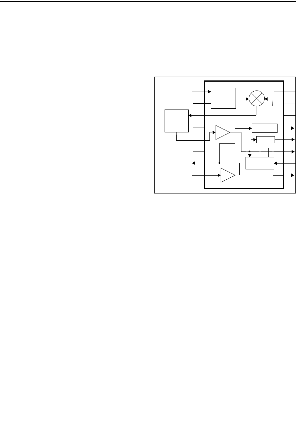
CIRCUIT DESCRIPTION
4-3 November 1999
Part No. 001-7780-500
frequency is low, the VCO-derived input to the phase
detector is lower than the TCXO-derived input (or the
phase lags the TCXO-derived input). Pin 15 of IC1
then pulses low and turns Q1 on. This charges the loop
filter capacitors which increases the VCO control
voltage. The VCO frequency then increases until the
phase detector inputs are again the same frequency and
phase. If the VCO frequency is too high, pin 16 pulses
high which discharges the loop filter capacitors.
The loop filter is formed by R7-R9 and C4/C5.
This is a low-pass filter which controls synthesizer
stability and lock-up time and suppresses the 6.25 kHz
reference frequency.
4.3 RECEIVER CIRCUIT DESCRIPTION
NOTE: A block diagram of the RF and logic units is
located on page 8-3.
4.3.1 RF AMPLIFIER (Q1), FIRST MIXER (Q2)
The receive signal from the antenna is fed
through low-pass filter FI7 and the antenna switch (see
Section 4.4.2) to bandpass filter FI1. This filter attenu-
ates the image and other unwanted frequencies and
also prevents the injection signal from being fed out to
the antenna.
The signal is then fed to RF amplifier Q1. Imped-
ance matching with FI1 is provided by L32, C4, C138,
and R104. The RF amplifier is used to recover filter
losses and improve the sensitivity of the receiver. The
output of Q1 is fed to FI2 which is a bandpass filter
similar to FI1. Impedance matching is provided by L5
and C7.
From FI2 the signal is fed to gate 1 of first mixer
Q2.Thisisadual-gateMOSFETdevicewhichmixes
the receive frequency with the first injection frequency
to produce a first IF of 45.225 MHz (low-side injec-
tion is used). The injection frequency is from the
synthesizer, and it is fed through a low-pass filter
consisting of C22-C24 and L12. This filter attenuates
harmonic frequencies present in the injection signal. A
3-dB pad consisting of R9-R11 provides the required
input level to the mixer, and L11 and C12 provide
matching.
Impedance matching on the input of Q2 is
provided by C11, L6-L8, and L33. Likewise, imped-
ance matching on the output is provided by C15, L9,
L10, C18, C19, and R99. The first IF signal is then fed
to four-pole crystal filter FI3. This filter attenuates
wideband noise, adjacent channels, frequencies
resulting from intermodulation, and other frequencies
close to the receive channel.
Figure 4-1 Limiter/Mixer/Detector IC3
4.3.2 IF AMPLIFIER (Q2), LIMITER/DETECTOR
(IC3)
From crystal filter FI3, the IF signal is fed to IF
amplifier Q2 on the IF board. This stage provides the
required input level to the next stage. The signal is
then fed to limiter/detector IC3. This device contains
second mixer and oscillator, limiter, detector, squelch,
and RSSI stages (see Figure 4-1).
The IF signal is fed in on pin 16 which is the
input of an internal mixer.The 45.225 MHz first IF
signal is mixed with the 44.775 MHz second injection
signal to produce a second IF of 450 kHz. The 44.775
injection signal is produced by multiplying the TCXO
frequency by three. This multiplication is performed
by Q18 and other components.
The 450 kHz second IF is fed out of IC3 on pin 3
and applied to ceramic filters FI6, FI5, and FI4. These
filters are used to attenuate wideband noise. A
switching network consisting of D13-D16 routes the
IF signal through all three filters with narrow band and
NPSPAC operation, and through only FI4 with wide-
band operation. This switching network is controlled
by WIDE and NAR signals from Q19-Q21. The W/N
44.775 MHz
2nd Injection 1
2
3
4
5
6
7
8
16
15
14
13
12
11
10
9
Oscillator
Mixer
Limiter-Amp
Quad.
45.225
450 kHz 2nd IF MHz
1st IF
44.775
MHz
FI4, FI5,
Ceramic Filters
FI6
Audio
RSSI
Noise Det
Amp Out
IF
Out
Detector

CIRCUIT DESCRIPTION
4-4
November 1999
Part No. 001-7780-500
input signal to these transistors is high for narrow
band channels. Therefore, with narrow band chan-
nels, D14/D16 are forward biased and D13/D15
reverse biased and vice versa for wideband channels.
The450kHzsignalfromthesefiltersisthenfed
backintoIC3onpin5andappliedtoalimiter-
amplifier stage. From the limiter the signal is fed to
the quadrature detector. An external phase-shift
network connected to pins 10 and 11 shifts the phase
of one of the detector inputs by 90° at 450 kHz (the
other inputs are unshifted in phase). This network
consists of C17 and ceramic discriminator X1. The
detector is adjusted for wide and narrow band chan-
nels by Q3, R8, and C16. The detected audio signal is
then amplified and fed out of IC3 on pin 9.
4.3.3 SQUELCH CIRCUIT (IC4A/B, IC5A)
The audio output signal on pin 9 of IC3 contains
audio and also high-frequency noise. This signal is fed
to the receive audio and data processing circuits on the
logic board (Section 4.6.1) and also to the squelch
circuit. The amount of noise in this signal tends to be
inversely proportional to signal strength (the higher
the noise level, the lower the signal strength and vice
versa). Therefore, it can be used for squelch control.
A bandpass filter that passes only noise frequen-
cies occurring above the audio band is formed by an
op amp in IC3 and external components. The input to
this filter is pin 8 and frequency determining compo-
nents (R17-R19, C20, C21) are connected to pin 7.
Other components on the input such as Q4 provide
frequency and wide/narrow band compensation, and
thermistors R14/R26 provide temperature compensa-
tion. The input audio/noise level is adjusted by R13.
The detected noise output on pin 13 of IC3 is applied
to pin 32 of the microprocessor in the logic unit.
4.4 TRANSMITTER DESCRIPTION
NOTE: A block diagram of the RF and logic units is
located on page 8-3.
4.4.1 AMPLIFIER (Q9), DRIVER (Q8)
In the transmit mode, the VCO output signal is
the transmit frequency. It is switched to the transmitter
by the switching circuit consisting of D7 and other
components (see Section 4.2.2) and applied to ampli-
fier Q9. Power to this stage and also Q8 is the 7.5-volt
battery supply switched by Q16 and Q17. This switch
is controlled by the switched T5V supply. Therefore,
when the transmit mode is selected, the TX5V supply
goes high which causes the output of Q17 to go low
and turn switch Q16 on.
The output signal from Q9 is fed to driver Q8
which provides additional amplification. Impedance
matching with IC1 is provided by L15, C62, and a
resistive pad consisting of R41-R43. Power amplifier
module IC1 provides up to 3 watts of RF power at the
antenna jack. It contains three internal amplifier
stages, each of which has a separate supply voltage
(VCC1-VCC3). The supply voltage to the first stage
(VCC1) is from the power control circuit, and the
supply voltage to the last two stages (VCC2/VCC3) is
the unswitched battery supply.
4.4.2 ANTENNA SWITCH AND LOW-PASS
FILTER
The antenna is switched between the receiver and
transmitter by an antenna switch consisting of D11,
D1-D3, and several other components. In the transmit
mode, the TMUT input on pin 2 of Q7 is high. The
T5V supply on pin 4 then appears on pin 3 and current
flows through R20, L14, D11, D3, and L1/D1 and
L2/D2. Since D11 and D3 are forward biased, the
transmit signal has a low impedance path to the
antenna.
L14/C31, L1/C2/D1, and L2/D2/C17 each form
discrete quarter-wave line that is AC grounded at one
end. When one end of a quarter-wave line is AC
grounded, the other end presents a high impedance to
the quarter-wave frequency. Therefore, L14/C31
isolate the 5-volt battery supply from transmitter RF,
and the other two circuits isolate the receiver. In the
receive mode, D11 and D1-D3 are no longer forward
biased. Therefore, the receive signal has a high-
impedance path into the transmitter and a low-imped-
ance path into the receiver. From the antenna switch
the transmit signal is fed to low-pass filter FI7. This
filter attenuates harmonic frequencies occurring above
the transmit band.

CIRCUIT DESCRIPTION
4-5 November 1999
Part No. 001-7780-500
4.4.3 POWER CONTROL (IC2A/B)
The power output circuit maintains a steady
power output level by controlling the supply voltage to
the first stage in power module IC1 (VCC1). The
output power is monitored using a directional coupler
consisting of L34, L13, C33, C35, D4, D5, and several
other components. Reflected (reverse) power is
detected by L13/D5, and forward power is detected by
L12/D4. These couplers produce a DC voltage that is
proportional to the reverse or forward power.
The forward power signal is amplified by IC2A
and is combined with the reverse power signal on pin
6 of IC2B. If there is no reverse power being detected,
IC2B amplifies only the difference between the
forward power signal on pin 6 and the reference
voltage on pin 5. This reference voltage controls the
power output, and it is set by the control logic through
potentiometer 2 in IC209 in the logic unit.
As forward or reverse power increases, the output
voltage on pin 7 decreases. Q5 and Q6 then turn off
more which decreases the supply voltage applied to
VCC1 of IC1. Power then decreases to maintain a
stable output. The opposite occurs if forward or
reverse power decrease. The power decrease resulting
from an increase in reverse power prevents transmitter
damage which may result if excessive power is
reflected back into the transmitter. This may occur, for
example, if the transmitter is keyed with a defective
antenna.
4.5 CONTROL LOGIC AND DISPLAY
NOTE: A block diagram of the RF and logic units is
located on page 8-3.
4.5.1 CONTROL LOGIC
The digital control logic is based on 8-bit CMOS
microprocessor IC306. The operating speed is set by
9.8304 MHz crystal X2. A clock shift signal applied
through D301. This signal goes high to shift the clock
frequency slightly when the second harmonic inter-
feres with the receive signal.
A serial data bus formed by MSI, MSO, and
MSCK (pins 49-51) is used to transfer data to and
from two external devices. They are 16K x 8
EEPROM IC304 and DTMF encoder IC303. Another
serial port formed by XTXD and XRXD is used to
transfer programming data to and from an external
computer. This port is fed out of the transceiver on
pins 6 and 7 of the accessory connector. Descriptions
of the IC306 pins are located in Table 4-1.
4.5.2 DISPLAY ASSEMBLY DESCRIPTION
IC1 on the display board is an intelligent LCD
display controller/driver. It communicates with the
microprocessor on the logic board over a serial bus
consisting of MSCK (serial clock) and MSO (serial
data), and DISST (display strobe) signals. IC1 is set
for 1/3 bias and 1/5 duty cycle and drives an 8-char-
acter, 14-segment display at a 98 Hz frame frequency.
The LCD display (DS6) has 127 segments that are
driven by a 34-segment signal with 4 common lines.
4.6 RECEIVE AUDIO PROCESSING
4.6.1 BANDPASS FILTER (IC101)
The receive audio and data signal from the IF
module in the RF unit is called DET. It is applied to
IC101 in the receive audio circuit, IC102 in the receive
data circuit, and IC110 in the SMARTNET data
circuit. The receive audio circuit operates as follows,
and the other circuits are described in later sections.
The DET signal is applied to IC101 which is a
bandpass filter which passes frequencies from 300-
3000 Hz. This attenuates Call Guard (CTCSS/DCS)
signaling and high-frequency harmonics. This filter
also provides de-emphasis of the audio signal.
On the input of IC101, pin 1 of Q110 is low in the
wideband mode and high in the narrow band mode.
Therefore, R102 is grounded in the wideband mode to
lower the input level to IC101. This maintains a
constant audio output level since the higher deviation
in the wideband mode results in a higher input level.
Also on the input of IC101, the NPSPAC line control-
ling Q111 is high when a NPSPAC channel is selected
and low at other times. This grounds R167 in the
NPSPAC mode to lower the input level since NPSPAC
channel deviation is higher than narrow band
deviation.

CIRCUIT DESCRIPTION
4-6
November 1999
Part No. 001-7780-500
Table 4-1 Microprocessor IC306 Pin Descriptions
Pin
Name Port Name Input or
Output Description Active High
or Low
1 RES Input Reset pulse input -
2 XTAL Input System clock connection terminal -
3 EXTAL Input System clock connection terminal -
4 FWE Input Not used -
5 MDI Input Flash ROM data import control (L=load) Low
6MDO -Notused -
7 NMI - Not used (external pull-up) -
8STBY -Notused -
9 VCC - Supply voltage -
10 CSHIFT Output Clock shift control (H=shift) High
11 - - Not used -
12 INTS I/O - -
13 RxD - Not used (external pull-up) -
14 TxD - Not used (external pull-up) -
15 VSS - Ground -
16 DTMFSO Output Segment data for LCD driver -
17 EXTDC Input Option signal input -
18 DTMFCK Output Clock signal for LDC driver -
19 - - - -
20 FCN Input FCN button switch Low
21 AUX Input AUX button switch Low
22 DPOTST Output Digi-pot strobe signal -
23 OFFREQI Input Main voltage supply switch Low
24 QSELOI Input Channel select switch input -
25 - - - -
26 SN_RX Input SMARTNET receive data input -
27 TXDATA Output Subaudible tone/main audio signal out -
28 RXDATA Input Receive data input -
29 BWC Output Transmit/receive data filter bandwidth signal output High
30 KEYR3 Input Key matrix scan in -
31 KeyR2 Input Key matrix scan in -
32 NOISE Input Noise pulse input/squelch control -
33 MMUTE Output Mutes microphone audio signal (L=mute) Low
34 TXPREC Output Subaudible signaling tone/damp signal output -
35 TEST Output Bypass transmit data filter (H=Normal/no bypass) High
36 L5V - Supply voltage -
37 L5V - Supply voltage -
38 BATIN Input Low battery voltage detection -
39 RSSI Input RSSI (Receive Signal Strength Indicator) -
40 - - - -
41 - - - -
42 - - - -
43 - - - -
44 - - - -
45 - - - -
46 VSS - Ground -

CIRCUIT DESCRIPTION
4-7 November 1999
Part No. 001-7780-500
.(<5 ,QSXW .H\PDWUL[VFDQ
.(<5 ,QSXW .H\PDWUL[VFDQ
062 2XWSXW 6HULDOGDWDRXWSXW
06, ,QSXW 6HULDOGDWDLQSXW
06&. 2XWSXW 6HULDOGDWDFORFN
5& 2XWSXW 59VXSSO\FRQWUROVLJQDO +LJK
%((3 2XWSXW $XGLREHHSWRQH
7& 2XWSXW 79VXSSO\FRQWUROVLJQDO +LJK
7087 2XWSXW $XWRPDWLF3RZHU&RQWURO$3&FLUFXLWFRQWUROVLJQDO +LJK
1363$& 2XWSXW &RQWUROV1363$&FKDQQHODXGLROHYHO+ 1363$&FKDQQHO +LJK
/9 6XSSO\YROWDJH
8/2&. ,QSXW 3//XQORFNHGVLJQDO+ XQORFNHG +LJK
7$ 2XWSXW 7DONDURXQGPRGHFRQWUROVLJQDO/ WDONDURXQG /RZ
3//67 2XWSXW 3//VWUREH
3//62 2XWSXW 3//GDWD
3//6. 2XWSXW 3//FORFN
:1 2XWSXW :LGHQDUURZEDQGVZLWFKLQJ+ QDUURZEDQG +LJK
37 2XWSXW &RPSDQGHUFRQWUROVLJQDO/ DFWLYH /RZ
',667 2XWSXW /&'GULYHUFKLSHQDEOHVLJQDO
',6(1 2XWSXW /&'GULYHUFKLSHQDEOHVLJQDO
966 *URXQG
966 *URXQG
2))54 2XWSXW 3RZHURIIFRQWUROVLJQDO+ KROGSRZHURQ /RZ
.(<6 2XWSXW .H\SDGPDWUL[VFDQ
.(<6 2XWSXW .H\SDGPDWUL[VFDQ
.(<6 2XWSXW .H\SDGPDWUL[VFDQ
.(<6 2XWSXW .H\SDGPDWUL[VFDQ
&/5&2'( 2XWSXW 2SWLRQDOHQFU\SWLRQFRQWUROVLJQDO /RZ
237% 2XWSXW 2SWLRQVLJQDO /RZ
%$7/(' 2XWSXW %$7/('FRQWUROVLJQDO/ /('RQ /RZ
%./(' 2XWSXW /&'EDFNOLJKWFRQWUROVLJQDO/ EDFNOLJKWRQ /RZ
'70)07 2XWSXW '70)PXWHFRQWUROVLJQDO/ PXWH /RZ
5087 2XWSXW 5HFHLYHDXGLRPXWHFRQWUROVLJQDO/ UHFHLYHDXGLRPXWH /RZ
$087 2XWSXW $XGLRDPSOLILHUVXSSO\YROWDJHFRQWURO+ HQDEOHG +LJK
46(/ ,QSXW &KDQQHOVHOHFWVZLWFKVLJQDO
46(/ ,QSXW &KDQQHOVHOHFWVZLWFKVLJQDO
46(/ ,QSXW &KDQQHOVHOHFWVZLWFKVLJQDO
46(/ ,QSXW &KDQQHOVHOHFWVZLWFKVLJQDO
%6</(' 2XWSXW %86</('FRQWUROVLJQDO/ /('RQ /RZ
7;/(' 2XWSXW 7;/('FRQWUROVLJQDO//('RQ /RZ
966 *URXQG
Table 4-1 Microprocessor IC306 Pin Descriptions (Continued)
3LQ
1DPH 3RUW1DPH ,QSXWRU
2XWSXW 'HVFULSWLRQ $FWLYH+LJK
RU/RZ

CIRCUIT DESCRIPTION
4-8
November 1999
Part No. 001-7780-500
93 S5C Output RF 5C supply control signal High
94 - - - -
95 SN_TR Output SMARTNET circuit control signal (H=SMARTNET Tx Data) High
96 EEPCS Output EEPROM chip select signal -
97 XTXD Output Programming data out -
98 XRXD Input Programming data in -
99 PTTIN Input PTT switch Low
100 - - - -
Table 4-1 Microprocessor IC306 Pin Descriptions (Continued)
Pin
Name Port Name Input or
Output Description Active High
or Low
4.6.2 EXPANDER (IC208)
From this filter the signal is fed to pin 7 of the
expander in IC208. When companding is enabled by a
low input on the PT input of IC208, this stage provides
1:2 expansion of the audio signal to remove the 2:1
compression that occurred when it was transmitted.
This compression and then expansion reduces the
amount of noise present in the audio signal. When the
PT input is high, companding is disabled and the
signal if fed through IC208 without expansion. NOTE:
Companding is not currently used with this radio.
The audio signal is fed out of IC208 on pin 15
and then fed to audio mute gate IC103. This gate is
controlled by the RMUTE output (pin 84) of the
microprocessor. The audio is also muted by the audio
amplifier as described in the information which
follows.
4.6.3 AUDIO AMPLIFIER (IC104-IC106)
From gate IC103, the audio signal is fed to
volume control R117 which sets the input level to the
audio amplifiers. Also applied at this point are the
DTMF and beep tones. Muting of the DTMF tones is
provided by Q101 which is controlled by the
DTMFMT output (pin 82) of the microprocessor. The
beep tones are synthesized by the BEEP output (pin
53) of the microprocessor.
The input level to the audio amplifiers is also
controlled by Q112 which lowers the input level by
grounding R168. Both the NPSPAC and W/B (wide/
narrow band) lines control Q112. Resistor R168 is
grounded only in the narrow band/non-NPSPAC mode
(see preceding information for line levels).
With normal operation when the internal speaker
is used, IC105 and IC106 provide the required amplifi-
cation. However, when an external speaker-micro-
phone is connected to pin 1 of the accessory jack (a
load of approximately 1k ohm or less), Q102 and
Q105 turn on and Q109 turns off. This disables IC105
and IC106, and enables IC104.
The supply voltage to all three audio amplifier
stages is controlled by Q106 and Q107. When the
audio is muted such as when no tones are sounding or
no message is being received, the AMUT output of the
microprocessor (pin 85) is low. This turns off both
Q106 and Q107 and removes supply voltage from the
audio amplifiers. This helps conserve battery power.
The receive audio signal is also muted by gate IC103
as previously described.
4.7 RECEIVE AND TRANSMIT DATA
PROCESSING
4.7.1 RECEIVE DATA FILTER/DETECTOR
(IC102A/B, IC107A/B)
The receive data (and audio) signal (DET) from
the IF board is also routed to the receive data filter
formed by IC102B and IC102A. This is a low-pass
filter which attenuates voice and other harmonic
frequencies above the data band.
The passband of this filter is controlled by the
BWC signal applied to Q103. When digital Call Guard
data or a low-frequency Call Guard tone is being
detected, the BWC signal is high which turns on
Q103. The cut-off frequency of the filter is then
approximately 150 Hz. Then when a high-frequency
Call Guard tone is received, Q103 turns off and the

CIRCUIT DESCRIPTION
4-9 November 1999
Part No. 001-7780-500
cut-off frequency is approximately 190 Hz. Q103
lowers the cut-off frequency of the filter by switching
additional capacitance into the filter.
From the filter the data signal is applied to a DC
restoration circuit formed by IC107B and IC107A.
This circuit converts the data signal from AC floating
at half supply to a digital signal at 0- and 5-volt levels
that can be read by the microprocessor. IC107B is a
standard noninverting amplifier with a gain of approx-
imately 5.6 set by R139 and R140 (R140 is AC
grounded by C129). Diodes D101 and D102 charge
and discharge C129 to establish a DC reference on
pins 2 and 6 of IC107 that is the average of the posi-
tive and negative going alternations of the data signal.
The amplified data signal is applied to pin 3 of
IC107A. When this level rises above the reference
level on pin 2, the output on pin 1 goes high (5 volts).
Conversely, when the data signal falls below the refer-
ence level, the output goes low (0 volts). In the
transmit mode, Q104 is turned on which effectively
grounds pin 3 of IC107A and forces the output on
pin 1 low.
4.7.2 TRANSMIT DATA FILTER (IC206B/
IC206A)
Thetransmitdatasignalisproducedbythe
TXDATA and TXPREC outputs of the micropro-
cessor (pins 27 and 34, see Table 4-1). A pseudo sine
wave is produced by the four voltage levels that can be
produced by these outputs. This signal is fed to a
transmit data filter formed by IC206B and IC206A.
This filter is the same as receive data filter IC102B
and IC102A described in the preceding section. This
filter attenuates harmonics present in the waveform
produced by the microprocessor.
The output and input of the data filter is fed to
gate IC203. This gate is used to bypass the transmit
data circuit during alignment so that a wide range of
harmonic frequencies are passed for use in setting
modulation balance. The control signal to this gate is
the TEST signal from pin 35 of the microprocessor.
This signal is low when the transmit data filter is
bypassed.
Thesignalisthenroutedtopin7orgateIC210
which selects either it or the SMARTNET data signal
from IC113B. The data output signal on IC210, pin 1
is then applied to pin 24 of IC209 which is the input to
one of the digitally controlled potentiometers in that
device. The data modulation level is set during align-
ment and controlled by the logic. The output on pins
22 and 23 is then fed to IC201 where it is combined
with the transmit audio signal (see Section 4.8.3).
4.8 TRANSMIT AUDIO PROCESSING
4.8.1 GATE (IC204), HIGH-PASS FILTER
(IC202)
The microphone audio signal is applied to pin 2
of one of the gates in IC204. This signal may come
from the internal microphone or an external micro-
phone connected to pin 8 of the accessory connector.
This gate is controlled by the MMUTE signal from pin
33 or the microprocessor. When this signal is low, the
microphone audio signal is muted.
The transmit DTMF tone is applied to pin 6 of
IC204 which is the input of the other gate in that
device. This gate is controlled by the DTMFMT signal
from pin 82 of the microprocessor, and when that
signal is low, the DTMF tone is muted.
The transmit audio and DTMF signals are then
combined and applied to pin 3 of compandor IC208.
When companding is enabled by a low input on the PT
input of IC208, this stage provides 2:1 compression of
the audio signal. This compression and then re-expan-
sion when it is received reduces the amount of noise
present in the audio signal. When the PT input of
IC208 is high, companding is disabled and the signal
is fed through IC208 without compression. NOTE:
Companding is not currently used with this radio.
The transmit audio/DTMF signal is fed out of
IC208 on pin 2 and applied to a high-pass filter formed
by IC202A. This filter has a –3 dB cutoff frequency of
approximately 300 Hz to attenuate frequencies that
could cause interference with the Call Guard signals.*
4.8.2 LIMITER (IC202B)
Pre-emphasis of the DTMF tone or microphone
audio signals is provided by C205/ R211. IC202B is
an amplifier functioning as a limiter (limiting occurs
when it saturates). Limiting prevents overmodulation

CIRCUIT DESCRIPTION
4-10
November 1999
Part No. 001-7780-500
caused by high input levels from the internal or
external microphone. The bias voltage to this stage
and also to IC201A is produced by voltage divider
R208/R207.
4.8.3 LOW-PASS FILTER (IC205A/B)
IC205A and IC205B form a low-pass splatter
filter which attenuates frequencies above approxi-
mately 3 kHz. This prevents adjacent channel interfer-
ence caused by the harmonic frequencies which result
from amplitude limiting.
The output signal from this filter is applied to
IC209 which contains four logic-controlled potentio-
meters. The transmit audio signal is applied to potenti-
ometer3onpin20andfedoutonpin19whichisthe
wiper of that potentiometer. The potentiometers in this
device are adjusted by the control logic via the serial
data bus (MSCK/MSO). The transmit audio/DTMF
level is set when the transceiver is aligned.
The transmit audio/DTMF signal is then fed to
IC201 where it is combined with the transmit data/
SMARTNET data signal if applicable. The output
signal on pin 4 of IC201 is then fed to the VCO in the
RFunitandalsotopins7and8ofIC209.Thesignal
fed to the RF unit (MOD) modulates the VCO, and the
signal fed to IC209 is level adjusted and fed out on pin
6 and applied to the RF unit where it modulates the
TCXO. The potentiometer is set by the logic during
alignment, and is used to balance the VCO and TCXO
modulation signals.
4.9 SMARTNET DATA PROCESSING
Both the transmit and receive SMARTNET/
SmartZone data signals are applied to a filter formed
by IC112A/B and IC113B. Switching of these signals
is provided by gate IC110 which is controlled by the
SN_TR signal from pin 95 of the microprocessor.
When this signal is high, the transmit data signal on
pin6isselectedisroutedtothefilter,andwhenitis
low the receive data signal on pin 7 is routed to the
filter.
IC112B, IC112A, and IC113B form a 1800 Hz
low-pass filter which attenuates unwanted frequencies
above the SMARTNET/SmartZone data band. The
output of this filter on U113B, pin 7 is then fed to
IC114A/B which provide DC restoration when data is
being received. The signal is also fed to gate IC210 in
the transmit data circuit to be transmitted when
applicable.
The DC restoration circuit formed by IC114A/B
and IC113A is similar to the receive data circuit
described in Section 4.7.1. It converts the data signal
from AC floating at half supply to DC levels of 0 and
5 volts that can be detected by the microprocessor.
Diodes D104 and D105 charge and discharge C158
andC157toestablishaDCreferenceonpin2of
comparator IC113A that is the average of the positive
and negative going alternations. Q106 turns on in the
transmit mode which grounds pin 2 and disables this
circuit.
In the transmit mode, gate IC210 selects either
the SMARTNET data signal or the Call Guard data
signal. It is controlled by the same SN_TR signal that
controls IC110. The output signal on pin 1 is then
applied to potentiometer 1 in IC209. Refer to Section
4.7.2 for more information on this circuit.

5-1 November 1999
Part No. 001-7780-500
BATTERY PACK AND CHARGER INFORMATION
SECTION 5 BATTERY PACK AND CHARGER INFORMATION
5.1 BATTERY PACK
CAUTION
Dispose of these batteries in accordance with local reg-
ulations. Do notdispose in a land fill. Do not incinerate
because an explosion may result.
5.1.1 GENERAL
Standard 1400 mAH Battery Pack, Part Number
587-8150-135, contains six size AA nickel metal-
hydride (Ni-MH) batteries connected in series. Also
inside the pack are a diode, thermistor, and thermal
circuit breaker. The diode protects against reverse
polarity when charging and also prevents discharge of
the battery through the charger. The thermistor is used
by the rapid charger to sense battery temperature.
Intrinsically Safe 1400 mAH Battery Pack, Part
Number 587-8150-136, is similar to the standard pack
except that it has a thermal fuse and series resistors
connected to the negative terminal of the battery. This
resistor limits current if a short circuit occurs.
The battery pack is a sealed unit that is not
intended to be serviced. If the pack fails to hold a
charge or is defective for some other reason, it must be
replaced with a new unit. The batteries in this pack
have a nominal capacity of 1400 mAH. Typical oper-
atingtimebeforerechargeisasfollows.Thisassumes
that the transceiver is in the standby mode (receive,
audio squelched) 90% of the time, the receive mode
(receive, rated audio out) 5% of the time, and the
transmit mode 5% of the time.
5.1.2 BATTERY CARE
With proper care, a battery pack should provide
many months of service. Some causes of shortened
battery life are as follows:
•Repeated deep discharge. Recharging should take
place soon after the low battery indication appears.
This indication appears when the battery pack
voltage drops to 6.3 volts which is approximately
1 volt per cell. Do not regularly continue operating
the transceiver until it is completely nonfunctional.
•Regularly recharging a battery after only light use.
This may result in shortened operating time. If this
has caused shortened operating time, it may be
possible to restore it to normal by performing three
complete discharge/charge cycles.
•Frequent use at temperature extremes. Maximum
battery life is achieved if the ambient temperature
when using or recharging a battery is 68-86° F (20-
30° C). The recommended temperature ranges for
the various battery functions are as follows.
•Regularly leaving fully charged battery packs in the
charger for extended periods (such as longer than
over a weekend).
•A short circuit condition that causes overheating
that could vent hydrogen and reduce life.
5.2 RAPID CHARGER
The single-unit rapid charger that is used to
charge this battery pack is listed in Table 1-1. Also
required is either the 117 or 220 VAC power supply.
The pack can be charged while attached to the trans-
ceiver; however, charge time may be slightly longer.
Typical charge time is as follows. This assumes that
the battery is discharged to the point where the low
battery indication appears.
Typical Battery Charge Time = 1 hour
This charger uses state-of-the-art ∆T/∆t (change
in temperature/change in time) and – ∆V (negative
Power Setting Operating Time
1 watt 8.6 hours
3 watts 7.5 hours
Function Fahrenheit Celsius
Charging +50 to +104° +10 to +40°
Actual Use +14 to +140° –10 to +60°
Storage –22 to +122° –30 to +50°

BATTERY PACK AND CHARGER INFORMATION
5-2
November 1999
Part No. 001-7780-500
change in voltage) sensing to determine when the
battery is nearly fully charged. This type of sensing
prolongs battery pack life because overcharging is
minimized.
Operation is in the fast charge mode until the
battery pack is approximately 95% charged. Charging
is then in the slow mode until the pack is removed
from the charger. With these battery packs, the fast
rate is approximately 1400 mA and the slow rate is
approximately 70 mA.
When the battery is inserted in the charger, the
red charge indicator turns on continuously to indicate
that charging in the fast mode is occurring. If this indi-
cator flashes at a slow rate when the pack is inserted, it
indicates that charging is occurring at the slow rate
because battery parameters are not within the required
range. The battery temperature must be within +50 to
+104° F (+10 to +40° C) and the battery voltage must
be above 6 volts for rapid charging to occur. When
these parameters reach the normal range, the charger
automatically switches to the fast rate.
The primary method used by these chargers to
detect a fully charged battery is to sense the point at
which the battery temperature begins increasing at a
faster rate (∆T/∆t). This normally provides the first
indication that the battery is fully charged. If this
method does not indicate a charged battery, the charger
also detects a negative change in battery voltage
(minus ∆V) which also indicates a fully charged
battery.
To provide fail-safe operation, the charger also
switches to the slow rate if the battery temperature
rises above approximately 113° F or total charge time
in the fast mode exceeds approximately 1.5 hours.
When the battery is fully charged, the charge
indicator begins flashing at a rapid rate and the slow
charge rate is selected. The charger then remains in
this mode until the battery is removed from the
charger.
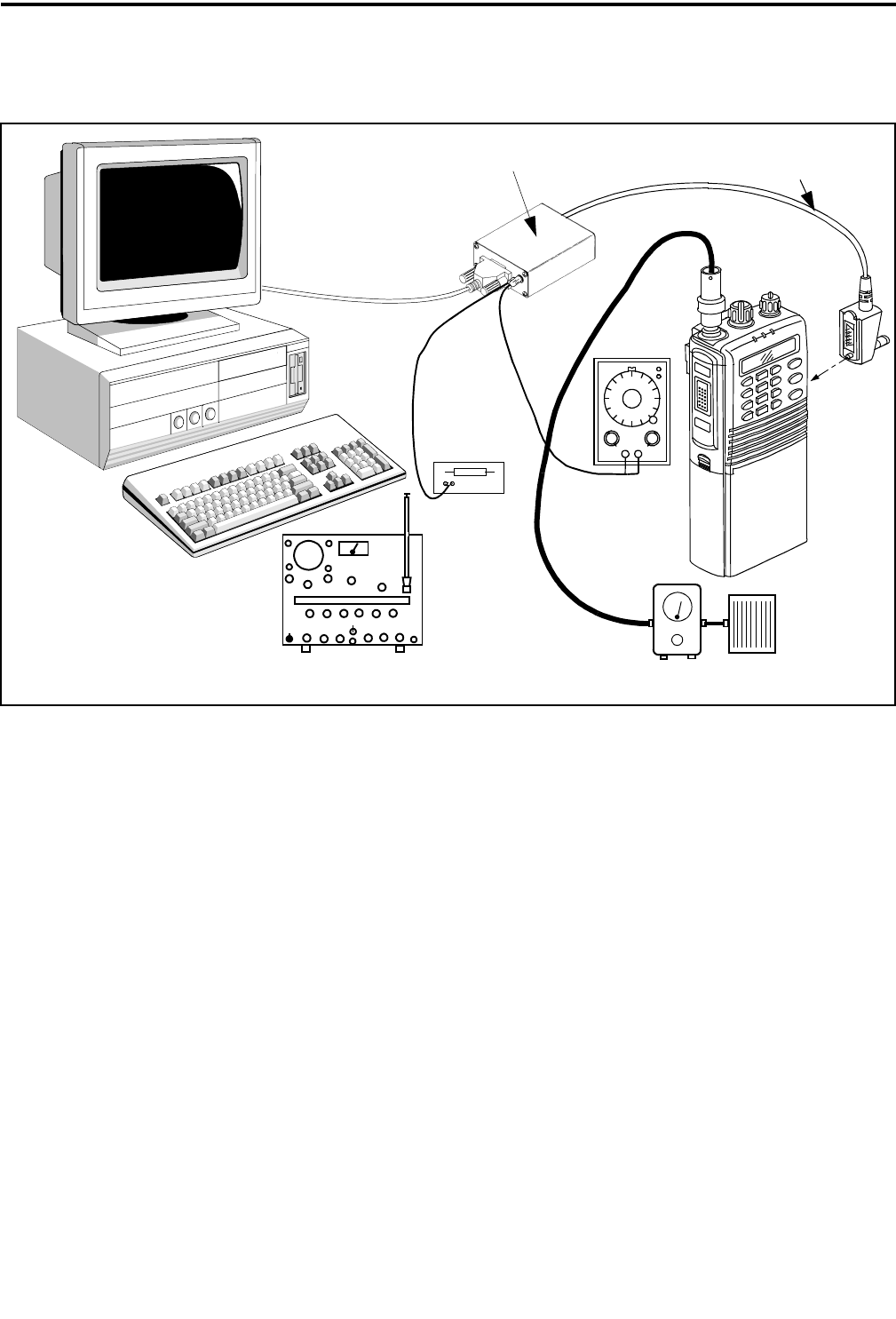
6-1 November 1999
Part No. 001-7780-500
ALIGNMENT PROCEDURE AND PERFORMANCE TESTS
SECTION 6 ALIGNMENT PROCEDURE AND PERFORMANCE TESTS
6.1 GENERAL
6.1.1 INTRODUCTION
The alignment procedure described in this section
should be performed if repairs are made that could
affect the factory alignment. In addition, before a
transceiver is initially placed in service, the perfor-
mance tests in Sections 6.8 and 6.9 should be
performed.
To perform the alignment described in this
section, special PCTune software (see Table 1-1) and
the same basic computer setup used for programming
is required. This equipment is shown above and also
described in Section 3.1. Only Remote Programming
Interface (RPI), Part No. 023-9800-000, can be used
because it is the only RPI that has microphone and
speaker audio jacks that are required for alignment.
Only two adjustments are made manually and the
others are made digitally using the PCTune software.
The two manual adjustments are squelch sensitivity
and TCXO frequency, and if they do not need to be
reset, the transceiver can be tuned without removing
the cover.
This transceiver does not have a special test mode
that is selected. The PCTune software automatically
selects the frequencies and other test conditions that
are required to perform the alignment. If the trans-
ceiver must be controlled manually to perform such
things as testing or troubleshooting, program tempo-
rary conventional channels.
6.1.2 TEST SETUP
Connect the test setup shown in Figure 6-1. Addi-
tional information follows on equipment in this setup.
Figure 6-1 Alignment Setup Diagram
Remote Programming Interface (RPI)
Signal Generator/ Wattmeter
50-ohm
Load
Comm. Monitor
Generator
Audio
PC-Compatible
Computer
Speaker Load
Part No. 023-9800-000 RPI-Transceiver Cable
Part No. 597-2002-123
680-Ohm
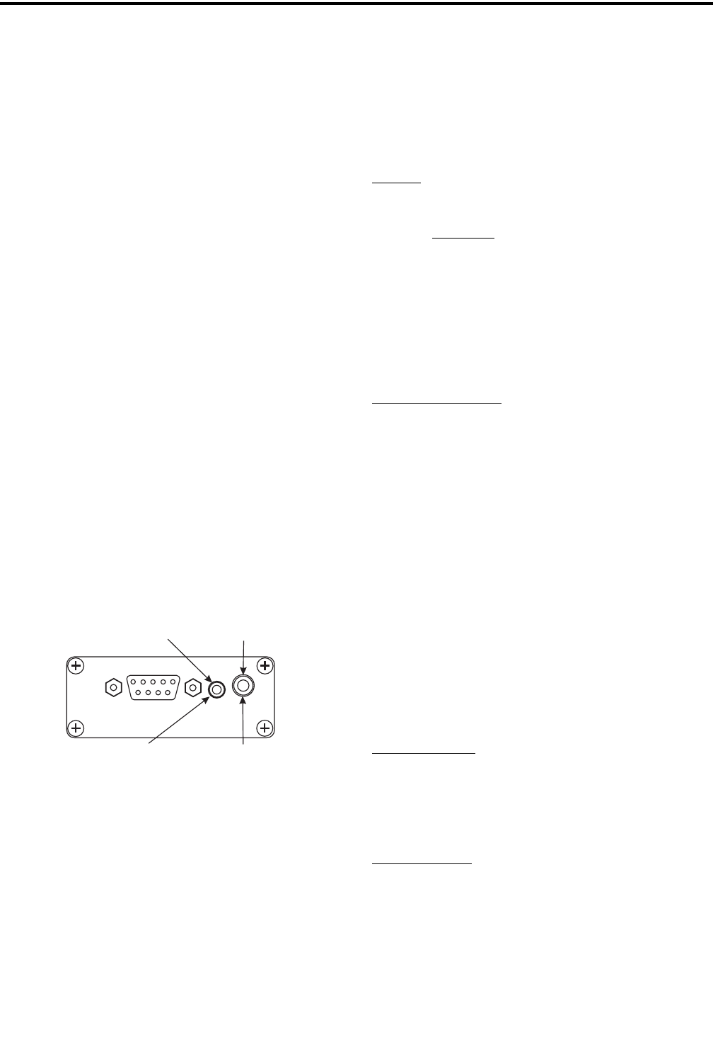
ALIGNMENT PROCEDURE AND PERFORMANCE TESTS
6-2
November 1999
Part No. 001-7780-500
$QWHQQD-DFN$GDSWHU7KHWUDQVFHLYHUDQWHQQDMDFN
LVDQ60$IHPDOHW\SH7KHUHIRUHVRPHVRUWRIDGDSWHU
PD\EHUHTXLUHGWRFRQQHFWWHVWHTXLSPHQWWRWKLVMDFN
$Q60$PDOHWR%1&IHPDOHDGDSWHULVDYDLODEOHE\
RUGHULQJ3DUW1R
5)6LJQDO*HQHUDWRU:KHQFRQQHFWLQJWKHJHQHU
DWRUWRWKHDQWHQQDMDFNXVHDWOHDVWDG%SDG
EHWZHHQWKHJHQHUDWRUDQGWUDQVFHLYHU7KLVSURWHFWV
WKHJHQHUDWRULIWKHWUDQVPLWWHULVDFFLGHQWDOO\NH\HG
DQGDOVRHQVXUHVWKDWDRKPORDGH[LVWV7KHLQSXW
OHYHOVOLVWHGLQWKH3&7XQHVFUHHQVDUHDWWKHDQWHQQD
MDFNVRLQFUHDVHWKHJHQHUDWRURXWSXWDFFRUGLQJO\
3RZHU6RXUFH,IDEDWWHU\LVXVHGWRSURYLGHWUDQV
FHLYHUSRZHUGXULQJDOLJQPHQWPDNHVXUHLWLVLQJRRG
FRQGLWLRQDQGIXOO\FKDUJHG3RZHURXWSXWOHYHOVDUH
ZLWKYROWVDSSOLHGWRWKHWUDQVFHLYHU7\SLFDO
FXUUHQWZKHQWUDQVPLWWLQJDWKLJKSRZHULV$
:DWWPHWHU/RDG7KHZDWWPHWHUDQGGXPP\ORDG
PXVWPHDVXUHDQGGLVVLSDWHXSWRDSSUR[LPDWHO\
ZDWWV)RUDFFXUDWHSRZHURXWSXWPHDVXUHPHQWDW
0+]XVHDPLQLPXPQXPEHURIFRQQHFWRUVZLWKD
7HIORQRUEHWWHUGLHOHFWULF,IFRD[LDOFDEOHLVXVHGLW
VKRXOGEHDPLQLPXPOHQJWKRIDORZORVVW\SH
$XGLR*HQHUDWRU7KHDXGLRJHQHUDWRULVFRQQHFWHG
WRWKHODUJHU´PRQRSKRQHMDFNRIWKH53,VKRZQ
EHORZ
6SHDNHU/RDG7KHVSHDNHUORDGLVFRQQHFWHGWRWKH
VPDOOHU´PRQRSKRQHMDFNRIWKH53,DVVKRZQ
DERYH7KLVLVDORZOHYHODXGLRRXWSXWWKDWUHTXLUHVD
ORDGRIDSSUR[LPDWHO\RKPV
&RPSXWHUDQG53,7KH53,LVFRQQHFWHGWRWKH
FRPSXWHUDQGWUDQVFHLYHUDVGHVFULEHGLQ6HFWLRQ
1RWHWKDW53,3DUW1RPXVWEH
XVHG2WKHU53,¶VGRQRWKDYHWKHMDFNVUHTXLUHGWR
LQMHFWPLFDXGLRDQGPRQLWRUVSHDNHUDXGLRZLWKD
FRPSXWHUFRQQHFWHGWRWKHDFFHVVRU\MDFN
6.1.3 TUNE SOFTWARE
*HQHUDO
7KH3&7XQHVRIWZDUHLVD:LQGRZVEDVHG
SURJUDP0LQLPXPVRIWZDUHDQGKDUGZDUHUHTXLUH
PHQWVDUHDVIROORZV
•:LQGRZV
•';RUIDVWHUPLFURSURFHVVRU
•PHJDE\WHVRI5$0
•PHJDE\WHVIUHHVSDFHDYDLODEOHRQKDUGGULYH
•$QDYDLODEOHVHULDOSRUW
6RIWZDUH,QVWDOODWLRQ
3URFHHGDVIROORZVWRLQVWDOOWKLVVRIWZDUH
&ORVHDOODSSOLFDWLRQVWKDWDUHFXUUHQWO\UXQQLQJ
RWKHUWKDQ:LQGRZV
,QVHUWWKHGLVNFRQWDLQLQJWKH3&7XQHVRIWZDUHLQ
GULYH$RU%
)URPWKH:LQGRZVWDVNEDUFKRRVH581DQG
RSHQ6(783(;(RQGULYH$RU%$OWHUQDWLYHO\
XVH)LOH([SORUHUDQGGRXEOHFOLFN6(783(;(
)ROORZWKHLQVWUXFWLRQVRQWKHVFUHHQ7KHSURJUDP
LVDXWRPDWLFDOO\ORDGHGRQWKHKDUGGULYHDQGVWDUW
XSVKRUWFXWVRUJURXSVDUHFUHDWHG
6WDUWLQJ3&7XQH
6HOHFW6WDUWLQWKHWDVNEDUWKHQ3URJUDPV!
3&7XQH!3&7XQH
([LWLQJ3&7XQH
&OLFNWKH3&7XQHORJRRQWKHOHIWHQGRIWKHWLWOH
EDUDQGVHOHFW³&ORVH´RUFOLFNWKH³;´EXWWRQRQWKH
ULJKWHQGRIWKHWLWOHEDU
Speaker Audio
Out Jack
Mic Audio In
Jack
2.6 mm/3/32”
Phone Jack
3.6 mm/1/8”
Phone Jack
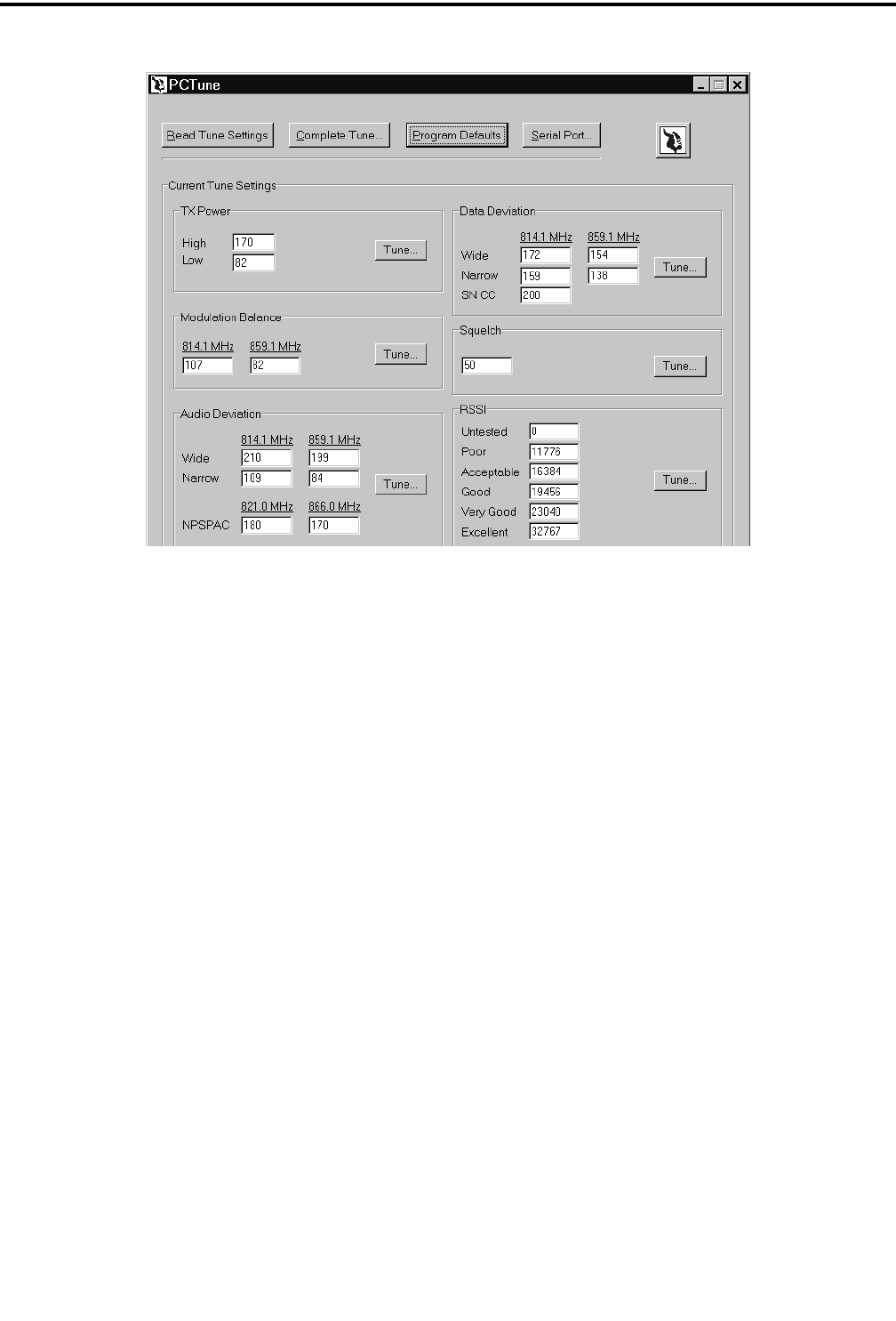
ALIGNMENT PROCEDURE AND PERFORMANCE TESTS
6-3 November 1999
Part No. 001-7780-500
Figure 6-2 PCTune Main Screen
6.1.4 PRELIMINARY SETUP
1. With transceiver power turned off, connect the RPI
to an unused serial port of the computer. Then
connect the RPI to the accessory jack of the trans-
ceiver using the cable indicated in Figure 6-1.
2. Start the PCTune program as described in the
preceding section and click the “Serial Port” button
near the top to display the selected serial port.
Change to the port being used if necessary.
3. Turn transceiver power on and the green indicator
on the RPI should light. Move the slide switch to the
other position if this indicator is amber.
6.1.5 MAIN PCTUNE SCREEN
ThemainPCTunescreenisshowninFigure6-2
above. The various adjustments that are performed are
show in the six boxes in the lower part of this screen.
To perform just one adjustment or perform the adjust-
ments individually, click the “Tune” button for the
applicable adjustment. To perform a complete align-
ment and have the program automatically step through
all adjustments, click the “Complete Tune” button on
the top. The functions of the various buttons in this
screen are as follows:
Read Tune Settings Button - Reads and displays the
various tune settings currently stored in the radio.
Complete Tune Button - Initiates the complete tuning
procedure as just described.
Program Defaults Button - Programs the transceiver
with the default settings for the various adjustments.
Thiscanbeusedtoquicklyrestorearadiototypical
settings.
Serial Port Button - Selects the serial port that is used
to connect the RPI to the computer. This setting only
needs to be made the first time the program is run or if
a different serial port is used.
Tune Buttons - These buttons are used to perform
individual adjustments without having to go through
the complete alignment procedure (see paragraph at
the beginning of this section).
EF Johnson Logo Button - Clicking this button
displays the PCTune version number.
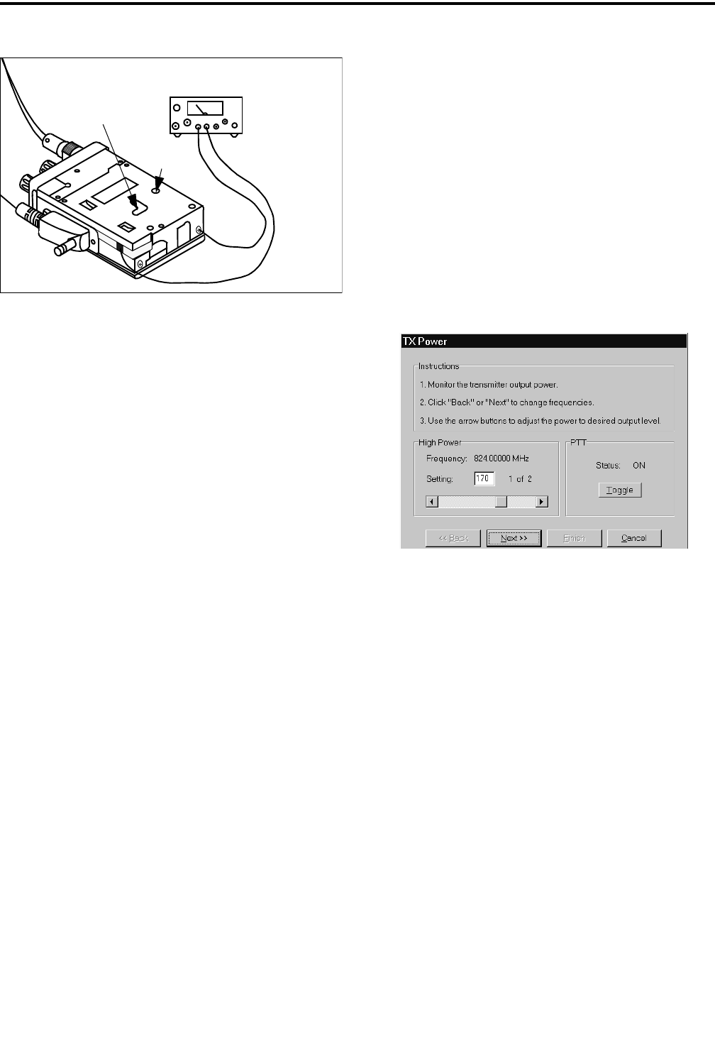
ALIGNMENT PROCEDURE AND PERFORMANCE TESTS
6-4
November 1999
Part No. 001-7780-500
Figure 6-3 Connecting DC Power
6.1.6 REMOVING TRANSCEIVER COVER
NOTE: The transceiver cover needs to be removed
only if the frequency and squelch adjustments
described in Sections 6.2.1 and 6.6 need to be reset.
The frequency and squelch noise level adjust-
ments are made by manually resetting controls on the
RF board. To access these controls, proceed as
follows:
1. Remove the battery, belt clip, and back cover as
described in Section 1.11.
2. An external power supply must then be connected to
the transceiver as shown in Figure 6-3.
6.2 TRANSMIT FREQUENCY AND POWER
6.2.1 FREQUENCY ADJUSTMENT
Frequency adjustment should be performed with
the ambient temperature near the TCXO calibration
reference of 77° F (25° C). This ensures that the
frequency will be within tolerance at the temperature
extremes. Proceed as follows:
NOTE: The transmitter immediately keys when the
following function is selected. To turn the transmitter
on and off, click the “Toggle” button (see screen
which follows).
1. Connect a wattmeter and dummy load to the antenna
jack as shown in Figure 6-1.
2. Click the “Complete Tune” button to automatically
go from one adjustment to the next or click the
“Tune” button in the “Tx Power” box to perform
only this adjustment.
3. Monitor the transmit frequency with a communica-
tions monitor set to the frequency displayed on the
screen.
4. At room temperature, this frequency should be
within ±400 Hz. If readjustment is required, remove
the cover as described in Section 6.1.6 and adjust
R73 (see Figure 6-3) for the correct frequency. This
also adjusts the receive frequency.
Transmit Power Adjustment Screen
6.2.2 POWER OUTPUT ADJUSTMENT
Set the high and low power output by clicking the
arrows or moving the button in the scroll bar. The rela-
tive power level is indicated by the number in the box.
Set the high and low power levels as follows:
High Power Level = 3.0 watts
Low Power Level =1.0watt
6.3 MODULATION BALANCE
1. If manually selecting each test, click the “Tune”
button in the “Modulation Balance” box. Otherwise,
this function is selected automatically when the
“Complete Tune” button is clicked.
2. View the transmit modulation waveform on the CRT
of a communication monitor. If applicable, set the
monitor for de-emphasis off, high-pass filter off,
low-pass filter 3 kHz, and FM peak detection active.
7.5 VDC
Power Supply
(–) Neg
(+) Pos
R73
(Freq Adj)
R13
(Sq Lvl Adj)

ALIGNMENT PROCEDURE AND PERFORMANCE TESTS
6-5 November 1999
Part No. 001-7780-500
3. Follow the instructions on the screen and adjust for
the best demodulated square wave with minimum
tilt and overshoot.
6.4 AUDIO DEVIATION
1. If manually selecting each test, click the “Tune”
button in the “Audio Deviation” box. Otherwise,
this function is selected automatically when the
“Complete Tune” button is clicked.
2. Inject a 1 kHz signal at the level indicated on the
screen into the Mic Audio jack of the RPI (see
Section 6.1.2).
3. Monitor the transmit modulation signal with a
communication monitor and follow the instructions
on the screen to adjust the wideband, narrow band,
and NPSPAC (see Section 1.2.5) deviation.
6.5 DATA DEVIATION
1. If manually selecting each test, click the “Tune”
button in the “Data Deviation” box. Otherwise, this
function is selected automatically when the
“Complete Tune” button is clicked.
2. Monitor the transmit modulation signal with a
communication monitor and follow the instructions
on the screen to adjust the wideband, narrow band,
and SMARTNET/SmartZone control channel
data deviation.
6.6 SQUELCH ADJUST
The input level to the noise squelch circuit is set
by R13 on the IF board, and the squelch threshold
level is set by the PCTune software. The factory
setting of R13 should not need to be changed, so step 3
which follows can normally be skipped. Proceed as
follows to set the squelch:
1. If manually selecting each test, click the “Tune”
button in the “Squelch” box. Otherwise, this func-
tion is selected automatically when the “Complete
Tune” button is clicked.
2. Connect an RF signal generator to the antenna jack
using a 6 dB or greater pad. Set the generator for the
channel frequency and modulation indicated on the
screen.
3. If R13 must be adjusted (see preceding), remove the
transceiver cover and connect power as described in
Section 6.1.6. Temporarily set the squelch for “50”
on the “Squelch” screen and adjust R13 (see Figure
6-3) so that the squelch just opens (audio is heard) at
8-9 dB SINAD.
4. Readjust the squelch level as indicated on the screen
so that the squelch opens and closes between the
indicated SINAD levels.
6.7 RSSI ADJUST
NOTE: Improperly setting the RSSI levels can result in
degraded SmartZone roaming operation. Therefore,
do not change the default settings unless you are
familiar with how roaming will be affected.
The function which adjusts the RSSI levels is
available only by clicking the “Tune” button in the
“RSSI” box. It is not displayed in the Complete Tune
mode for the reason just described. The default values
that are programmed by clicking the “Program
Defaults” button (see Section 6.1.5) should not be
changed unless you are familiar with how these levels
control site switching in a SmartZone system.

ALIGNMENT PROCEDURE AND PERFORMANCE TESTS
6-6
November 1999
Part No. 001-7780-500
PERFORMANCE TESTS
6.8 RECEIVER PERFORMANCE TESTS
6.8.1 PRELIMINARY SETUP
This transceiver does not have a special test mode
that can be selected to perform testing. Therefore,
temporary conventional channels are programmed to
perform this function. Program channels near the low,
middle, and high ends of the band (wideband, narrow
band or both) and with and without Call Guard
(CTCSS/DCS) squelch as applicable. In addition, to
check high and low power and talk-around operation,
program High/Low Power and Repeater Talk-Around
option switches. Proceed as follows to check receiver
operation:
1. Select the channel near the center of the band
(around 860 MHz).
2. Connect the signal generator to the antenna jack (see
Section 6.1.2 for more information). Set the output
to the channel frequency, modulated with 1 kHz at 3
kHz (wideband channels) or 1.5 kHz deviation
(narrow band channels).
6.8.2 SINAD SENSITIVITY
NOTE: The audio output level of the accessory con-
nector is at a lower level than at the internal speaker.
In addition, the internal speaker automatically mutes
when a load of approximately 1k ohm or less is con-
nected to this output.
1. Connect a SINAD meter to the speaker output of the
RPI (see Section 6.1.2).
2. Decrease the signal generator output to obtain a 12
dB reading on the SINAD meter. The signal gener-
ator output should be 0.35 µV maximum. If
required, temporarily readjust squelch for “0” as
described in Section 6.6. (after clicking “Read Tune
Settings” to note the current setting).
3. Check both wide and narrow band channels if appli-
cable, and also check the channels on each end of
the band. Reset the squelch to the previous level if it
was changed.
6.8.3 SQUELCH SENSITIVITY
With the test setup used for the preceding test,
slowly increase the signal generator output until the
squelch just opens (audio is enabled). Then decrease
the signal generator output until it just closes. The
squelch should open after 12 dB SINAD and close
before 6 dB SINAD.
6.8.4 AUDIO POWER AND DISTORTION
CAUTION
Grounding either speaker terminal may damage the
audio amplifier. Therefore, make sure that any meter
connected across the speaker has floating inputs.
To measure audio output power, the actual level
across the speaker must be measured because full
output power is not available at the accessory
connector. If a load of approximately 1k ohm or less is
connected to the speaker output of the accessory
connector, it must be disconnected to enable the
internal speaker. Proceed as follows:
1. Remove the transceiver cover and connect power as
described in Section 6.1.6. Carefully turn the front
cover over to access the speaker.
2. Connect an AC voltmeter and distortion meter
across the speaker (make sure they have floating
inputs). Alternatively, 100 µF, non-polarized capac-
itors can be used in series with the leads.
3. Set the signal generator output for –60 dBm (220
µV). Minimum audio power should be 0.5 watt
across the 16-ohm speaker (2.8 V rms). Distortion
should be less than 5% at 0.5 watt.
6.8.5 RECEIVER CURRENT DRAIN
Maximum transceiver current with 0.5-watt audio
output is 300 mA. With the receiver squelched, it
should be 92 mA maximum.

ALIGNMENT PROCEDURE AND PERFORMANCE TESTS
6-7 November 1999
Part No. 001-7780-500
6.9 TRANSMITTER PERFORMANCE TESTS
6.9.1 POWER OUTPUT
Refer to Section 6.8.1 for information on test
channels. Proceed as follows:
1. Connect a wattmeter and dummy load to the antenna
jack as described in Section 6.1.2.
2. Key the transmitter and high power output should be
2.8-3.5 watts. Check channels on both ends of the
band.
3. Select the talk-around mode by pressing the Talk-
Around option switch. The talk-around mode is
indicated by in the display. Key the transmitter
and power output should be 2.5 watts or greater.
Check channels on both ends of the band.
4. Select the low power mode by pressing the High/
Low Power option switch. Low power is indicated
by “LOW” in the lower part of the display. Power
output should be 0.8-1.2 watt in the standard mode
and 0.7-1.2 watt in the talk-around mode.
6.9.2 TRANSMIT FREQUENCY
Monitor the transmit frequency with a communi-
cation monitor set to the channel frequency. At room
temperature, the frequency should be within ± 400 Hz.
This also checks the receive frequency.
6.9.3 TRANSMIT MODULATION
1. Select a channel not programmed for Call Guard
(CTCSS/DCS) squelch and monitor the transmit
signal with a communication monitor. Speak into
the microphone with a normal voice and modulation
should be approximately 3.4 kHz (wideband) or 1.4
kHz (narrow band).
2. Select a channel programmed for Call Guard
squelch and with no voice or other microphone
input signal, data deviation should be 1.0 kHz
(wideband) or 0.8 kHz (narrow band) ± 200 Hz.
3. Speak into the microphone with the channel
programmed for Call Guard squelch selected.
Maximum total audio and Call Guard deviation
should be 4.7 kHz (wideband) or 2.3 kHz (narrow
band).
6.9.4 TRANSMITTER CURRENT DRAIN
Maximum current drain in the transmit mode
should be as follows:
High Power, Standard Mode - 1.75 A
High Power, Talk-Around Mode - 2.0 A
Low Power, both modes - 1.3 A

ALIGNMENT PROCEDURE AND PERFORMANCE TESTS
6-8
November 1999
Part No. 001-7780-500
This page intentionally left blank.

7-1 November 1999
Part No. 001-7780-500
PARTS LIST
SECTION 7 PARTS LIST
RefNo. Description PartNo.
CHASSIS PARTS
EP 01 B-3826B #1125-3A (chassis flex) 022-3906-001
EP 02 B-3827C #1125-3B (PTT sw flex) 022-3907-001
F 1 MCA-3 (CCV-3A) fuse 022-3907-037
J 1 3A3-M10 antenna connector 022-3906-124
MP 01 1125 metal chassis-2 022-3906-196
MP 02 1125 top plastic panel (b)-2 022-3907-057
MP 03 1591 top rubber sheet 022-3906-276
MP 04 Screw, 0-1 fh m2x4.5 ni b 022-3907-068
MP 05 VR nut (E) 022-3906-222
MP 06 VR nut (F) 022-3906-223
MP 07 VR nut (I) 022-3906-224
MP 08 1125 top seal 022-3906-271
MP 10 Knob N230 (large) 022-3907-067
MP 12 Knob N231 (small) 022-3907-066
MP 13 1125 accessory jack cover 022-3906-204
MP 16 Screw m2x4.5 zk 022-3906-211
MP 17 Screw B 4 022-3906-212
MP 18 1591 rear plastic panel-1 022-3907-056
MP 22 1591 contact base 022-3906-245
MP 23 1125 battery release button-1 022-3906-228
MP 24 1125 battery release spring-1 022-3906-232
MP 25 1125 plus terminal(A)-1 022-3906-236
MP 26 1591 plus plate 022-3906-246
MP 27 1125 fuse plate 022-3906-237
MP 28 1591 contact pin 022-3906-234
MP 29 Spring (F) rubber contact 022-3906-225
MP 30 1125 minus plate 022-3906-235
MP 32 Screw ph b0 2x4 sus 022-3906-221
MP 33 Screw ph m2x6 sus 022-3906-218
MP 34 Screw ph m2x9 sus 022-3906-219
MP 35 Screw ph m2x23 sus zk 022-3906-220
MP 36 Screw ph 0 m2 x3.5 ni 022-3906-215
MP 37 Screw 1 m2x4.5 zk for RF PA 022-3906-211
MP 39 Screw ph 0 m2 x3.5 ni 022-3906-215
MP 43 Screw ph b0 2x4 sus 022-3906-221
MP 45 Screw ph m2x2.5 zk 022-3906-216
MP 46 1591 RF shield-2 022-3907-063
MP 47 Round stut (G) 022-3906-275
MP 49 1591 antenna jack plate 022-3907-073
MP 50 Himerio-sheet (X) 022-3906-268
MP 52 FCC serial No. sticker (AZ)-1 022-3907-061
MP 59 Insulation plate (BI) 022-3907-071
MP 60 2176 earth plate 022-3907-076
MP 61 Thermal sheet (I) 022-3907-075
MP 62 Rubber sheet (L) 022-3907-072
MP 63 Sponge (cp) srcn 022-3906-269
MP 64 Sponge (BJ) 022-3907-070
JACK ASSEMBLY
J 01 YM-260 accessory jack 022-3906-125
EP 01 B-3829C (#1125-3A) flex circuit 022-3906-003
MP 01 1125 jack panel-1 022-3906-198
MP 02 1125 jack rubber (A)-1 022-3906-238
MP 03 1125 jack plate 022-3906-233
MP 04 Screw ph m2x2.5 zk 022-3906-216
MP 05 1591 jack sheet 022-3906-279
DISPLAY ASSEMBLY
C 1 C1608 CH 1H 330J-T-A 022-3906-070
C 2 680P C1608 B 022-3906-355
C 3 C1608 JB 1C 473K-T-A 022-3906-080
C 4 C1608 JB 1C 104KT-N 022-3906-614
C 5 C1608 CH 1H 330J-T-A 022-3906-070
C 6 C1608 JB 1C 104KT-N 022-3906-614
C 7 C1608 JB 1C 104KT-N 022-3906-614
DS 1 LNG310M6URA LED 022-3906-637
DS 2 LNG310M6URA LED 022-3906-637
DS 3 SEC1601C LED 022-3906-101
DS 4 SEC1401C 022-3906-100
DS 5 SEC 1801C LED 022-3906-102
DS 6 LD-BU10394J 022-3907-036
DS 7 LNG310M6URA LED 022-3906-637
DS 8 LNG310M6URA LED 022-3906-637
EP 1 B-5186A #2176-2D display PC bd
10-key 022-3907-006
B-5186A #2176-3D display PC bd
3-key 022-3907-086
EP 2 SRCN-1125-SG 022-3906-240
EP 3 LCD reflector plate 022-3907-048
Ref No. Description Part No.

PARTS LIST
7-2
November 1999
Part No. 001-7780-500
IC 1 LC75834W 022-3907-015
J 1 52204-2990 022-3906-128
J 2 AXN820735 022-3906-132
MP 01 10-key front panel (plastic) 022-3907-058
3-key front panel (plastic) 022-3907-087
MP 04 10-key rubber keypad 022-3907-077
3-key rubber keypad 022-3907-089
MP 06 1125 sp rubber-1 (10-key) 022-3906-270
1121 mic seal-1 (3-key) 022-3907-090
MP 07 1125 LCD holder 022-3906-227
MP 08 1591 front plate-1 022-3907-059
MP 09 Screw ph no.0b01.4x4.5ni 022-3906-266
MP 10 Screw ph b0 #.0-3 m1.4x3.5 blk 022-3906-214
MP 11 1125 front seal 022-3906-239
MP 12 Screw b0 2x4 ni (bt) 022-3906-213
MP 15 1125 display plate (10-key) 022-3906-243
1591 display plate (3-key) 022-3907-088
MP 16 Sponge (cp) srcn 022-3906-269
Q 1 2SA1576 S transistor 022-3906-029
Q 2 2SA1576 S transistor 022-3906-029
Q 3 2SA1576 S transistor 022-3906-029
Q 4 2SA1576 S transistor 022-3906-029
R 01 ERJ3GEYJ 103V resistor 022-3906-163
R 02 EFJ3GEYJ 151 V resistor 022-3906-145
R 03 ERJ3GEYJ 332 V resistor 022-3906-159
R 07 NTCCM16084LH 473KC resistor 022-3907-053
R 08 ERJ3GEYJ 473 V resistor 022-3906-171
R 09 ERJ3GEYJ 104 V resistor 022-3906-175
R 11 ERJ3GEYJ 473 V resistor 022-3906-171
R 12 ERJ3GEYJ 102 V resistor 022-3906-154
R 13 ERJ3GEYJ 473 V resistor 022-3906-171
R 14 ERJ3GEYJ 102 V resistor 022-3906-154
R 15 ERJ3GEYJ 473 V resistor 022-3906-171
R 16 ERJ3GEYJ821V resistor 022-3906-153
R 17 EFJ3GEYJ 151 V resistor 022-3906-145
R 18 12K ERJ3GE resistor 022-3906-164
Ref No. Description Part No.
3-KEY ASSEMBLY
EP 1 B-5188B #2176-3D (3-key PC bd) 022-3907-091
C 1 C1608 CH 1H 330J-T-A 022-3906-070
C 2 C1608 CH 1H 330J-T-A 022-3906-070
C 3 C1608 CH 1H 330J-T-A 022-3906-070
C 4 C1608 CH 1H 330J-T-A 022-3906-070
C 5 C1608 CH 1H 330J-T-A 022-3906-070
DS 1 LN1371G-(TR) display/LED 022-3906-098
DS 2 LN1371G-(TR) display/LED 022-3906-098
DS 3 LN1371G-(TR) display/LED 022-3906-098
DS 4 LN1371G-(TR) display/LED 022-3906-098
J 1 AXN720535 022-3906-131
MC 1 EM-123H microphone 022-3906-195
Q 1 2SA1576 S transistor 022-3906-029
R 1 ERJ3GEYJ 333 V resistor 022-3906-169
R 2 ERJ3GEYJ 104 V resistor 022-3906-175
R 3 ERJ3GEYJ 104 V resistor 022-3906-175
R 4 ERJ3GEYJ 104 V resistor 022-3906-175
R 5 ERJ3GEYJ 104 V resistor 022-3906-175
R 6 ERJ3GEYJ 221 V resistor 022-3906-288
R 8 ERJ3GEYJ 103V resistor 022-3906-163
R 10 ERJ3GEYJ 121V resistor 022-3906-144
R 11 ERJ3GEYJ 121V resistor 022-3906-144
R 12 ERJ3GEYJ 103V resistor 022-3906-163
SP 1 EAS3P127J speaker 022-3906-058
W 1 ERDS2T0 resistor to spkr 022-3906-877
W 2 ERDS2T0 resistor to spkr 022-3906-877
W 3 OPC-677 022-3907-069
W 4 OPC-677 022-3907-069
10-KEY ASSEMBLY
EP 1 B-5187C #2176-2D (10-key PC bd) 022-3907-007
C 1 C1608 CH 1H 330J-T-A 022-3906-070
C 2 C1608 CH 1H 330J-T-A 022-3906-070
C 3 C1608 CH 1H 330J-T-A 022-3906-070
C 4 C1608 CH 1H 330J-T-A 022-3906-070
Ref No. Description Part No.
DISPLAY ASSEMBLY

PARTS LIST
7-3 November 1999
Part No. 001-7780-500
C 5 C1608 CH 1H 330J-T-A 022-3906-070
DS 1 LN1371G-(TR) display/LED 022-3906-098
DS 2 LN1371G-(TR) display/LED 022-3906-098
DS 3 LN1371G-(TR) display/LED 022-3906-098
DS 4 LN1371G-(TR) display/LED 022-3906-098
J 1 AXN720535 022-3906-131
MC 1 EM-123H microphone 022-3906-195
Q 1 2SA1576 S transistor 022-3906-029
R 1 ERJ3GEYJ 333 V resistor 022-3906-169
R 2 ERJ3GEYJ 104 V resistor 022-3906-175
R 3 ERJ3GEYJ 104 V resistor 022-3906-175
R 4 ERJ3GEYJ 104 V resistor 022-3906-175
R 5 ERJ3GEYJ 104 V resistor 022-3906-175
R 10 ERJ3GEYJ 121V resistor 022-3906-144
R 11 ERJ3GEYJ 121V resistor 022-3906-144
R 12 ERJ3GEYJ 103V resistor 022-3906-163
SP 1 EAS3P127J speaker 022-3906-058
W 1 ERDS2T0 resistor to spkr 022-3906-877
W 2 ERDS2T0 resistor to spkr 022-3906-877
W 3 OPC-677 022-3907-069
W 4 OPC-677 022-3907-069
IF ASSEMBLY
C 01 4.7 16V MSVA 022-3906-097
C 02 C1068 JB 1H 102K-T-A 022-3906-060
C 03 C1608 JB 1C 473K-T-A 022-3906-080
C 04 TEMSVA 1A 106M-8L 022-3906-096
C 05 C1068 JB 1H 102K-T-A 022-3906-060
C 06 TEMSVA 1A 106M-8L 022-3906-096
C 07 TEMSVA 1A 106M-8L 022-3906-096
C 08 C1608 JB 1C 104KT-N 022-3906-614
C 09 C1608 JB 1E 103KTA 022-3906-063
C 10 C1608 CH 1H 180J-T-A 022-3906-068
C 11 C1608 JB 1E 103KTA 022-3906-063
C 12 C1608 JB 1E 103KTA 022-3906-063
C 13 C1608 JB 1E 103KTA 022-3906-063
C 14 C1608 JB 1E 103KTA 022-3906-063
C 15 4.7 16V MSVA 022-3906-097
C 16 C1068 JB 1H 102K-T-A 022-3906-060
RefNo. Description PartNo.
C 17 C1608 CH 1H 680J-T-A diode 022-3906-798
C 18 C1608 JB 1C 104KT-N 022-3906-614
C 19 C1068 JB 1H 102K-T-A 022-3906-060
C 20 C1608 CH 1H 221J-T-A 022-3906-603
C 21 C1608 CH 1H 221J-T-A 022-3906-603
C 23 C1068 JB 1H 102K-T-A 022-3906-060
C 24 C1068 JB 1H 102K-T-A 022-3906-060
C 25 C1068 JB 1H 102K-T-A 022-3906-060
C 26 C1608 CH 1H 330J-T-A 022-3906-070
C 29 C1608 JB 1C 104KT-N 022-3906-614
C 30 C1608 JB 1E 103KTA 022-3906-063
C 31 C1608 JB 1C 104KT-N 022-3906-614
C 32 820P C1608 B 022-3906-083
C 33 C1608 JB 1C 473K-T-A 022-3906-080
C 34 C1068 JB 1H 102K-T-A 022-3906-060
C 35 C1608 CH 1H 330J-T-A 022-3906-070
D 2 MA8056 M diode 022-3906-049
D 3 MA2S728-(TX) diode 022-3907-026
EP 1 B-5183C (#2176-1C) 022-3907-003
IC 1 TK11350BM 022-3907-020
IC 2 TK11360BM 022-3907-019
IC 3 TA31136FN8(EL) IC 022-3907-008
L 2 ELJNC R56J 0.56U 022-3906-122
Q 1 2SC4081 T107 S transistor 022-3906-031
Q 2 2SK882 GR (TE85L) transistor 022-3906-515
Q 3 DTC144EE TL transistor 022-3906-329
Q 4 UMG2N TL diode 022-3906-250
R 02 ERJ3GEYJ 472 V resistor 022-3906-160
R 04 ERJ3GEUJ 560V resistor 022-3906-142
R 05 ERJ3GEYJ 181 V resistor 022-3906-146
R 07 ERJ3GEYJ 222 V resistor 022-3906-157
R 08 ERJ3GEYJ 272 V resistor 022-3906-158
R 09 ERJ3GEYJ 331 V resistor 022-3906-389
R 12 ERJ3GEYJ 682 V resistor 022-3906-162
R 13 RV-222 (RH03AVAS4J 47K) 022-3906-516
R 14 NTCCM16084LH 104KC 022-3907-052
R 15 ERJ3GEYJ 473 V resistor 022-3906-171
R 16 ERJ3GEYJ 101 V resistor 022-3906-143
R 17 330K ERJ3GE resistor 022-3906-180
R 18 ERJ3GEYJ 102 V resistor 022-3906-154
R 19 ERJ3GEYJ 474 V resistor 022-3906-181
R 20 ERJ3GEYJ 103V resistor 022-3906-163
Ref No. Description Part No.
10-KEY ASSEMBLY IF ASSEMBLY

PARTS LIST
7-4
November 1999
Part No. 001-7780-500
R 21 ERJ3GEYJ 104 V resistor 022-3906-175
R 22 ERJ3GEYJ 331 V resistor 022-3906-389
R 23 ERJ3GEYJ 152 V resistor 022-3906-155
R 24 ERJ3GEYJ 122 V resistor 022-3906-390
R 25 ERJ3GEYJ 104 V resistor 022-3906-175
R 26 NTCCM16084BH 222KC 022-3907-055
R 27 ERJ3GEYJ 222 V resistor 022-3906-157
R 28 ERJ3GEYJ 682 V resistor 022-3906-162
X 1 CDBCA450CX24 resistor 022-3906-642
PLL ASSEMBLY
EP 1 B-5184C (#2176-1C) 022-3907-004
C 01 TEMSVA 1A 106M-8L 022-3906-096
C 02 C1608 CH 1H 330J-T-A 022-3906-070
C 04 C1608 JB 1C 104KT-N 022-3906-614
C 05 1.5 16V SVA 022-3906-094
C 07 C1608 CH 1H 330J-T-A 022-3906-070
C 08 C1608 CH 1H 330J-T-A 022-3906-070
C 09 C1608 CH 1H 330J-T-A 022-3906-070
C 10 C1068 JB 1H 102K-T-A 022-3906-060
C 11 C1608 CH 1H 150J-T-A 022-3906-067
C 12 C1608 JB 1C 473K-T-A 022-3906-080
C 13 C1608 CH 1H 330J-T-A 022-3906-070
C 14 C1608 JB 1C 473K-T-A 022-3906-080
C 15 C1608 CH 1H 180J-T-A 022-3906-068
C 16 12P C1608 CH 022-3906-066
C 17 C1608 JB 1C 104KT-N 022-3906-614
IC 1 MB15A02PFV-1 022-3907-016
IC 2 TC7S66FU IC 022-3906-020
L 1 MLF1608A 2R2K-T coil 022-3906-514
Q 1 2SA1576 S transistor 022-3906-029
Q 2 2SC4081 T107 S transistor 022-3906-031
Q 3 DTC144EE TL transistor 022-3906-329
R 01 ERJ3GEYJ 562 V resistor 022-3906-161
R 10 ERJ3GEYJ 103V resistor 022-3906-163
R 12 ERJ3GEYJ 472 V resistor 022-3906-160
R 13 ERJ3GEYJ 182 V resistor 022-3906-156
R 14 ERJ3GEYJ 471 V resistor 022-3906-150
R 15 ERJ3GEYJ 682 V resistor 022-3906-162
R 16 270 ERJ3GE resistor 022-3906-147
R 02 NTCCM16084BH 222KC 022-3907-055
Ref No. Description Part No.
R 03 ERJ3GEYJ 101 V resistor 022-3906-143
R 04 ERJ3GEYJ 332 V resistor 022-3906-159
R 05 NTCCM16084BH 152KC 022-3907-054
R 06 EFJ3GEYJ 151 V resistor 022-3906-145
R 07 ERJ3GEYJ 101 V resistor 022-3906-143
R 08 ERJ3GEYJ 122 V resistor 022-3906-390
R 09 ERJ3GEYJ 272 V resistor 022-3906-158
Ref No. Description Part No.
RF UNIT
C 001 C1608 CH 1H 0R3B-T-A 022-3906-468
C 002 C1608 CH 1H 040B-T-A 022-3906-609
C 004 C1608 CH 1H 330J-T-A 022-3906-070
C 005 C1608 CH 1H 330J-T-A 022-3906-070
C 007 C1608 CH 1H 030B-T-A 022-3906-489
C 008 C1608 JB 1C 473K-T-A 022-3906-080
C 009 C1608 CH 1H 330J-T-A 022-3906-070
C 010 C1608 CH 1H 330J-T-A 022-3906-070
C 011 C1608 CH 1H 010B-T-A 022-3906-085
C 012 C1608 CH 1H 330J-T-A 022-3906-070
C 013 C1608 CH 1H 330J-T-A 022-3906-070
C 014 C1608 JB 1E 103KTA 022-3906-063
C 015 C1608 CH 1H 180J-T-A 022-3906-068
C 016 C1608 CH 1H 330J-T-A 022-3906-070
C 017 C1608 JB 1E 103KTA 022-3906-063
C 018 C1608 JB 1E 103KTA 022-3906-063
C 019 C1608 CH 1H 040B-T-A 022-3906-609
C 020 C1608 JB 1E 103KTA 022-3906-063
C 022 C1608 CH 1H 330J-T-A 022-3906-070
C 023 C1608 CH 3R-5B-T-A 022-3906-353
C 024 C1608 CH 3R-5B-T-A 022-3906-353
C 025 C1608 CH 1H 330J-T-A 022-3906-070
C 026 12P C1608 CH 022-3906-066
C 027 C1608 JB 1C 104KT-N 022-3906-614
C 028 C1608 JB 1C 104KT-N 022-3906-614
C 029 C1608 JB 1C 104KT-N 022-3906-614
C 030 C1608 CH 1H 330J-T-A 022-3906-070
C 031 C1608 CH 1H 330J-T-A 022-3906-070
C 032 C1608 CH 1H 330J-T-A 022-3906-070
C 033 C1608 CH 1H 050C-T-A 022-3906-064
C 034 C1608 JB 1H 471K-T-A 022-3906-059
Ref No. Description Part No.
IF ASSEMBLY

PARTS LIST
7-5 November 1999
Part No. 001-7780-500
C 035 C1608 CH 1H 040B-T-A 022-3906-609
C 036 C1608 CH 1H 150J-T-A 022-3906-067
C 037 C1608 CH 1H 330J-T-A 022-3906-070
C 038 C1608 CH 1H 330J-T-A 022-3906-070
C 040 C1608 JB 1C 473K-T-A 022-3906-080
C 041 C1608 JB 1H 471K-T-A 022-3906-059
C 042 C1608 CH 1H 330J-T-A 022-3906-070
C 043 C1608 CH 1H 330J-T-A 022-3906-070
C 044 C1608 JB 1H 471K-T-A 022-3906-059
C 045 C1608 JB 1C 104KT-N 022-3906-614
C 046 C1608 CH 1H 330J-T-A 022-3906-070
C 047 C1608 CH 1H 330J-T-A 022-3906-070
C 048 C1608 CH 1H 330J-T-A 022-3906-070
C 049 C1608 CH 1H 330J-T-A 022-3906-070
C 050 C1608 CH 1H 330J-T-A 022-3906-070
C 052 C1608 CH 1H 330J-T-A 022-3906-070
C 053 4.7 16V MSVA 022-3906-097
C 054 C1608 CH 1H 330J-T-A 022-3906-070
C 055 C1608 CH 1H 180J-T-A 022-3906-068
C 057 4.7 16V MSVA 022-3906-097
C 058 C1608 CH 1H 330J-T-A 022-3906-070
C 059 C1608 CH 1H 330J-T-A 022-3906-070
C 060 C1608 CH 1H 330J-T-A 022-3906-070
C 062 C1608 CH 1H 050C-T-A 022-3906-064
C 063 C1608 CH 1H 330J-T-A 022-3906-070
C 064 C1608 CH 1H 330J-T-A 022-3906-070
C 065 C1608 CH 1H 330J-T-A 022-3906-070
C 066 C1608 CH 1H 2R5B-T-A 022-3906-071
C 067 C1608 CH 1H 330J-T-A 022-3906-070
C 068 C1608 CH 1H 330J-T-A 022-3906-070
C 069 C1608 CH 1H 330J-T-A 022-3906-070
C 070 C1608 CH 1H 330J-T-A 022-3906-070
C 071 C1608 JB 1H 471K-T-A 022-3906-059
C 072 C1608 CH 1H 330J-T-A 022-3906-070
C 073 C1608 CH 1H 330J-T-A 022-3906-070
C 074 C1608 JB 1C 473K-T-A 022-3906-080
C 075 C1608 CH 1H 020B-T-A 022-3906-086
C 076 C1608 CH 1H 330J-T-A 022-3906-070
C 077 C1608 CH 1H 330J-T-A 022-3906-070
C 078 C1608 CH 1H 050C-T-A 022-3906-064
C 079 C1608 CH 1H 330J-T-A 022-3906-070
C 080 C1608 CH 1H 330J-T-A 022-3906-070
C 081 C1608 CH 1H 330J-T-A 022-3906-070
C 082 C1608 CH 1H 330J-T-A 022-3906-070
C 083 C1608 CH 1H 1R5B-T-A 022-3906-087
Ref No. Description Part No.
C 084 C1608 CH 1H 330J-T-A 022-3906-070
C 085 C1608 CH 1H 330J-T-A 022-3906-070
C 088 C1608 CH 1H 330J-T-A 022-3906-070
C 089 C1608 JB 1C 104KT-N 022-3906-614
C 090 C1608 CH 1H 330J-T-A 022-3906-070
C 091 C1608 JB 1C 473K-T-A 022-3906-080
C 093 C1608 CH 1H 330J-T-A 022-3906-070
C 094 C1608 CH 1H 330J-T-A 022-3906-070
C 095 C1608 JB 1C 104KT-N 022-3906-614
C 096 C1608 CH 1H 330J-T-A 022-3906-070
C 097 C1608 CH 1H 330J-T-A 022-3906-070
C 098 C1608 CH 1H 330J-T-A 022-3906-070
C 100 C1608 CH 1H 330J-T-A 022-3906-070
C 101 C1608 CH 1H 330J-T-A 022-3906-070
C 102 C1608 CH 1H 330J-T-A 022-3906-070
C 103 C1608 CH 1H 330J-T-A 022-3906-070
C 104 C1608 CH 1H 330J-T-A 022-3906-070
C 105 C1608 CH 1H 330J-T-A 022-3906-070
C 106 C1608 CH 1H 330J-T-A 022-3906-070
C 107 C1608 CH 1H 330J-T-A 022-3906-070
C 108 C1608 CH 1H 330J-T-A 022-3906-070
C 109 C1608 CH 1H 330J-T-A 022-3906-070
C 111 C1608 CH 1H 330J-T-A 022-3906-070
C 112 C1608 CH 1H 330J-T-A 022-3906-070
C 114 C1608 JB 1C 473K-T-A 022-3906-080
C 117 C1608 CH 1H 070D T-A 022-3906-596
C 119 C1608 JB 1C 473K-T-A 022-3906-080
C 120 C1608 CH 1H 330J-T-A 022-3906-070
C 121 C1608 CH 1H 330J-T-A 022-3906-070
C 122 1 C2012 10V B 022-3907-034
C 124 C1608 JB 1C 104KT-N 022-3906-614
C 125 C1608 CH 1H 330J-T-A 022-3906-070
C 126 0.5P C1608 CH 0.1P 022-3906-084
C 127 C1608 CH 1H 330J-T-A 022-3906-070
C 128 C1608 JB 1E 103KTA 022-3906-063
C 129 C1608 JB 1E 103KTA 022-3906-063
C 130 C1608 JB 1E 103KTA 022-3906-063
C 131 C1608 CH 1H 330J-T-A 022-3906-070
C 132 C1608 CH 1H 050C-T-A 022-3906-064
C 133 C1608 CH 1H 330J-T-A 022-3906-070
C 134 C1608 CH 1H 030B-T-A 022-3906-489
C 135 C1608 JB 1E 103KTA 022-3906-063
C 136 C1608 CH 1H 150J-T-A 022-3906-067
C 137 C1608 CH 1H 330J-T-A 022-3906-070
C 138 C1608 CH 1H 150J-T-A 022-3906-067
Ref No. Description Part No.
RF UNIT

PARTS LIST
7-6
November 1999
Part No. 001-7780-500
C 139 C1608 JB 1C 104KT-N 022-3906-614
C 140 0.5P C1608 CH 0.1P 022-3906-084
D 01 MA77 (TW) diode 022-3906-047
D 02 MA77 (TW) diode 022-3906-047
D 03 UM9401F diode 022-3906-937
D 04 HSM88AS-TR diode 022-3906-046
D 05 HSM88AS-TR diode 022-3906-046
D 06 MA2S111-(TX) diode 022-3906-050
D 07 MA78 022-3906-044
D 09 MA2S111-(TX) diode 022-3906-050
D 10 MA2S111-(TX) diode 022-3906-050
D 11 UM9401F diode 022-3906-937
D 13 MA2S077-(TX) diode 022-3907-027
D 14 MA2S077-(TX) diode 022-3907-027
D 15 MA2S077-(TX) diode 022-3907-027
D 16 MA2S077-(TX) diode 022-3907-027
EP 1 B-5182C (#2176-1C) 022-3907-002
FI 1 EZF-U860 AM81T filter 022-3906-055
FI 2 EZF-U860 BM81T filter 022-3906-056
FI 3 FL-295 022-3907-028
FI 4 SFPC450E-TC01 filter 022-3907-030
FI 5 CFUM450F 022-3907-031
FI 6 SFPC450G-TC01 ceramic 022-3907-029
FI 7 GLP802-2 filter 022-3906-505
IC 1 M67706/SC1140 IC 022-3901-337
IC 1 M67706/SC1140 IC 022-3901-337
IC 2 NJM2904V-TE1 IC 022-3906-016
IC 3 NVCO-SM-838 S.IC 022-3906-135
IC 4 TC75S54F 022-3907-013
J 1 AXK6S30645P 022-3907-046
L 02 LQN1A 8N8J04 8.8N coil 022-3906-109
L 05 ELJRE 10NJ 10N coil 022-3906-493
L 06 ELJRE 18NJ 18N coil 022-3906-959
L 06 ELJRE 18NJ 18N coil 022-3906-959
L 07 ELJRE 68NG-F coil 022-3906-671
L 08 ELJRE 39NJ 39N coil 022-3906-953
L 09 ELJNC R47K 0.47U coil 022-3907-041
L 1 LQN1A 8N8J04 8.8N coil 022-3906-109
L 10 ELJNC R18K 0.18U coil 022-3906-956
Ref No. Description Part No.
L 11 ELJRE 33NJ 33N coil 022-3907-043
L 12 ELJRE 10NJ 10N coil 022-3906-493
L 13 DCS3220-09 coil 022-3906-121
L 14 ELJRE 39NJ 39N coil 022-3906-953
L 15 ELJRE 8N2J 8.2N coil 022-3906-491
L 16 MLF1608A 1R0M-T coil 022-3906-110
L 17 ELJRE 6N8J 6.8N coil 022-3906-496
L 19 ELJRE 12NJ 12N coil 022-3906-497
L 20 ELJRE 12NJ 12N coil 022-3906-497
L 22 ELJRE 15NJ 15N coil 022-3906-668
L 23 MLF1608A 1R0M-T coil 022-3906-110
L 24 BLM21P300S 022-3907-044
L 25 BLM21P300S 022-3907-044
L 26 BLM21P300S 022-3907-044
L 27 MLF1608D R33K 0.33U 022-3907-040
L 28 MLF1608D R33K 0.33U 022-3907-040
L 29 ELJRE 3N9J 3.9N coil 022-3907-042
L 30 MLF1608A 2R2K-T coil 022-3906-514
L 32 ELJRE 10NJ 10N coil 022-3906-493
L 33 ELJRE 8N2J 8.2N coil 022-3906-491
L 34 DCS3220-09 coil 022-3906-121
MP 03 1591 module T-shield (under IC1) 022-3906-262
MP 04 1781 module plate (VCO-IC1) 022-3906-508
MP 05 2176 shield plate (over Q2) 022-3907-065
MP 06 2176 shield sheet (over FI2) 022-3907-074
MP 07 1591 VCO shield case-1 022-3906-509
MP 08 1591 VCO sheet (shield insulator) 022-3906-281
MP 09 Grand spring (E) 022-3906-510
MP 10 1591 VCO shield cover plate-1 022-3906-298
Q 01 2SC5015 022-3906-035
Q 02 3SK177 U72 022-3906-037
Q 05 2SC4081 T107 S transistor 022-3906-031
Q 06 2SB1132 T100 Q transistor 022-3906-030
Q 07 UMD3 TL diode 022-3906-040
Q 08 2SC3357-T2 RF transistor 022-3907-022
Q 09 2SC3357-T2 RF transistor 022-3907-022
Q 10 2SC4228-T2 R44 transistor 022-3906-033
Q 11 2SC4228-T2 R44 transistor 022-3906-033
Q 12 2SC4228-T2 R44 transistor 022-3906-033
Q 13 2SA1576 S transistor 022-3906-029
Q 14 XP4601(TX) transistor 022-3906-328
Q 16 2SA1577 T107 Q transistor 022-3906-249
Q 17 DTC144EE TL transistor 022-3906-329
Ref No. Description Part No.
RF UNIT

PARTS LIST
7-7 November 1999
Part No. 001-7780-500
Q 18 2SC4215-Y transistor 022-3906-320
Q 19 DTA144EE transistor 022-3907-024
Q 20 DTA144EE transistor 022-3907-024
Q 21 DTC144EE TL transistor 022-3906-329
R 001 DRJ3GEYJ 561 V resistor 022-3906-151
R 002 ERJ3GEYJ 472 V resistor 022-3906-160
R 003 ERJ3GEYJ 182 V resistor 022-3906-156
R 004 56K ERJ3GE resistor 022-3906-172
R 005 ERJ3GEYJ 333 V resistor 022-3906-169
R 006 ERJ3GEUJ 560V resistor 022-3906-142
R 007 ERJ3GEYJ 181 V resistor 022-3906-146
R 009 270 ERJ3GE resistor 022-3906-147
R 010 18 ERJ3GE resistor 022-3906-140
R 011 270 ERJ3GE resistor 022-3906-147
R 012 ERJ3GEYJ 102 V resistor 022-3906-154
R 020 82 MCR10 resistor 022-3907-049
R 021 ERJ3GEYJ 102 V resistor 022-3906-154
R 022 ERJ3GEYJ 102 V resistor 022-3906-154
R 023 ERJ3GEYJ 103V resistor 022-3906-163
R 024 ERJ3GEYJ 473 V resistor 022-3906-171
R 025 ERJ3GEYJ 103V resistor 022-3906-163
R 026 ERJ3GEYJ 104 V resistor 022-3906-175
R 027 ERJ3GEYJ 104 V resistor 022-3906-175
R 028 56K ERJ3GE resistor 022-3906-172
R 029 ERJ3GEYJ 333 V resistor 022-3906-169
R 030 ERJ3GEYJ 182 V resistor 022-3906-156
R 031 ERJ3GEYJ 332 V resistor 022-3906-159
R 032 ERJ3GEYJ 104 V resistor 022-3906-175
R 033 ERJ3GEYJ 273 V resistor 022-3906-168
R 034 ERJ3GEYJ 103V resistor 022-3906-163
R 035 ERJ3GEYJ 224V resistor 022-3906-178
R 036 ERJ3GEYJ 221 V resistor 022-3906-288
R 037 ERJ3GEYJ 101 V resistor 022-3906-143
R 039 ERJ3GEYJ 473 V resistor 022-3906-171
R 041 ERJ3GEYJ 471 V resistor 022-3906-150
R 042 ERJ3GEYJ 100V 10 OHM resistor 022-3906-138
R 043 ERJ3GEYJ 471 V resistor 022-3906-150
R 044 ERJ3GEYJ 220V resistor 022-3906-685
R 045 ERJ3GEYJ 272 V resistor 022-3906-158
R 046 ERJ3GEYJ 100V 10 ohm resistor 022-3906-138
R 047 15 ERJ3GE resistor 022-3906-139
R 048 ERJ3GEYJ 472 V resistor 022-3906-160
R 049 ERJ3GEYJ 122 V resistor 022-3906-390
R 050 ERJ3GEYJ 472 V resistor 022-3906-160
Ref No. Description Part No.
R 051 ERJ3GEYJ 472 V resistor 022-3906-160
R 052 ERJ3GEUJ 560V resistor 022-3906-142
R 053 39K ERJ3GE resistor 022-3906-170
R 054 DRJ3GEYJ 561 V resistor 022-3906-151
R 055 ERJ3GEYJ 392 V resistor 022-3906-391
R 056 ERJ3GEYJ 222 V resistor 022-3906-157
R 057 15 ERJ3GE resistor 022-3906-139
R 058 15 ERJ3GE resistor 022-3906-139
R 059 15 ERJ3GE resistor 022-3906-139
R 060 270 ERJ3GE resistor 022-3906-147
R 061 18 ERJ3GE resistor 022-3906-140
R 062 270 ERJ3GE resistor 022-3906-147
R 063 ERJ3GEYJ821V resistor 022-3906-153
R 064 ERJ3GEYJ 682 V resistor 022-3906-162
R 065 ERJ3GEYJ 182 V resistor 022-3906-156
R 066 ERJ3GEUJ 560V resistor 022-3906-142
R 067 ERJ3GEYJ 473 V resistor 022-3906-171
R 068 ERJ3GEYJ 104 V resistor 022-3906-175
R 069 ERJ3GEYJ 104 V resistor 022-3906-175
R 072 ERJ3GEYJ 104 V resistor 022-3906-175
R 073 EVM-1X B54 50K resistor 022-3907-051
R 074 ERJ3GEYJ 104 V resistor 022-3906-175
R 075 ERJ3GEYJ 104 V resistor 022-3906-175
R 076 ERJ3GEYJ 223 V resistor 022-3906-167
R 077 ERJ3GEYJ 103V resistor 022-3906-163
R 078 ERJ3GEYJ 222 V resistor 022-3906-157
R 079 ERJ3GEYJ 272 V resistor 022-3906-158
R 080 ERJ3GEYJ 332 V resistor 022-3906-159
R 082 ERJ3GEYJ 104 V resistor 022-3906-175
R 083 ERJ3GEYJ 220V resistor 022-3906-685
R 085 ERJ3GEUJ 560V resistor 022-3906-142
R 086 ERJ3GEYJ 122 V resistor 022-3906-390
R 087 ERJ3GEYJ 474 V resistor 022-3906-181
R 091 12K ERJ3GE resistor 022-3906-164
R 092 ERJ3GEYJ 100V 10 OHM resistor 022-3906-138
R 093 15K ERJ3GE resistor 022-3906-165
R 094 ERJ3GEYJ 103V resistor 022-3906-163
R 095 ERJ3GEYJ 223 V resistor 022-3906-167
R 096 15K ERJ3GE resistor 022-3906-165
R 097 ERJ3GEYJ 102 V resistor 022-3906-154
R 098 ERJ3GEYJ 391 V resistor 022-3906-149
R 099 ERJ3GEYJ 471 V resistor 022-3906-150
R 101 ERJ3GEYJ 103V resistor 022-3906-163
R 102 ERJ3GEYJ 682 V resistor 022-3906-162
R 103 ERJ3GEYJ 272 V resistor 022-3906-158
Ref No. Description Part No.
RF UNIT

PARTS LIST
7-8
November 1999
Part No. 001-7780-500
R 104 DRJ3GEYJ 561 V resistor 022-3906-151
W 1 IPS-1041-2 022-3906-133
W 3 ERJ3GE-JPW V resistor 022-3906-185
W 4 ERJ3GE-JPW V resistor 022-3906-185
W 5 ERJ3GE-JPW V resistor 022-3906-185
W 6 ERJ3GE-JPW V resistor 022-3906-185
X 3 CR-626 022-3907-038
Ref No. Description Part No.
LOGIC UNIT
C 001 C1608 CH 1H 330J-T-A 022-3906-070
C 002 C1608 CH 1H 330J-T-A 022-3906-070
C 003 C1608 CH 1H 330J-T-A 022-3906-070
C 004 C1608 CH 1H 330J-T-A 022-3906-070
C 005 C1608 CH 1H 330J-T-A 022-3906-070
C 006 C1608 CH 1H 330J-T-A 022-3906-070
C 007 C1608 CH 1H 330J-T-A 022-3906-070
C 008 C1608 CH 1H 330J-T-A 022-3906-070
C 009 C1608 CH 1H 330J-T-A 022-3906-070
C 010 C1608 CH 1H 330J-T-A 022-3906-070
C 011 C1608 CH 1H 330J-T-A 022-3906-070
C 012 C1608 CH 1H 330J-T-A 022-3906-070
C 013 C1608 CH 1H 330J-T-A 022-3906-070
C 014 C1608 CH 1H 330J-T-A 022-3906-070
C 015 C1608 CH 1H 330J-T-A 022-3906-070
C 016 C1608 JB 1E 103KTA 022-3906-063
C 017 C1608 JB 1E 103KTA 022-3906-063
C 018 C1608 JB 1E 103KTA 022-3906-063
C 019 C1608 JB 1E 103KTA 022-3906-063
C 020 C1608 CH 1H 330J-T-A 022-3906-070
C 021 C1608 JF 1C 104Z-T-A 022-3906-076
C 022 C1608 JB 1E 103KTA 022-3906-063
C 023 C1608 CH 1H 330J-T-A 022-3906-070
C 024 C1608 CH 1H 330J-T-A 022-3906-070
C 025 C1608 CH 1H 330J-T-A 022-3906-070
C 026 C1608 JB 1E 103KTA 022-3906-063
C 027 C1608 CH 1H 330J-T-A 022-3906-070
C 028 C1608 CH 1H 330J-T-A 022-3906-070
C 029 C1608 CH 1H 330J-T-A 022-3906-070
Ref No. Description Part No.
C 030 C1608 JB 1C 104KT-N 022-3906-614
C 031 C1608 JB 1C 104KT-N 022-3906-614
C 032 C1608 CH 1H 330J-T-A 022-3906-070
C 033 C1608 CH 1H 330J-T-A 022-3906-070
C 036 C1608 CH 1H 330J-T-A 022-3906-070
C 043 C1608 JF 1C 104Z-T-A 022-3906-076
C 044 C1608 JF 1C 104Z-T-A 022-3906-076
C 045 C1608 JF 1C 104Z-T-A 022-3906-076
C 046 1 C2012 10V B 022-3907-034
C 048 C1608 JF 1C 104Z-T-A 022-3906-076
C 049 C1608 JF 1C 104Z-T-A 022-3906-076
C 051 C1608 JF 1C 104Z-T-A 022-3906-076
C 052 C1608 JF 1C 104Z-T-A 022-3906-076
C 053 C1608 JF 1C 104Z-T-A 022-3906-076
C 054 C1608 JF 1C 104Z-T-A 022-3906-076
C 055 C1608 JB 1E 103KTA 022-3906-063
C 101 C1608 JB 1E 103KTA 022-3906-063
C 102 470P C1608 CH 022-3906-252
C 103 C1068 JB 1H 102K-T-A 022-3906-060
C 104 0.039 C1608 16V B 022-3907-033
C 105 C1608 JB 1E 103KTA 022-3906-063
C 106 C1608 JB 1E 103KTA 022-3906-063
C 107 1 C2012 10V B 022-3907-034
C 108 C1608 JB 1C 104KT-N 022-3906-614
C 109 C1608 JB 1E 103KTA 022-3906-063
C 110 C1608 JB 1C 473K-T-A 022-3906-080
C 111 4.7 C3216 6.3V B 022-3907-035
C 113 C1608 CH 1H 330J-T-A 022-3906-070
C 115 1 C2012 10V B 022-3907-034
C 116 C1608 JB 1C 473K-T-A 022-3906-080
C 118 C1608 JB 1C 104KT-N 022-3906-614
C 121 C1608 JB 1C 104KT-N 022-3906-614
C 122 C1608 JB 1C 104KT-N 022-3906-614
C 123 TEMSVB2 1A 336M-8R 022-3906-095
C 124 C1608 JB 1E 103KTA 022-3906-063
C 125 C1608 JB 1E 103KTA 022-3906-063
C 126 0.0033 C1608 B 022-3906-077
C 127 C1608 JB 1C 104KT-N 022-3906-614
C 128 C1608 JB 1H 222K-T-A 022-3906-061
C 129 4.7 10V MSVA 022-3906-361
C 130 1 C2012 10V B 022-3907-034
C 134 1 C2012 10V B 022-3907-034
C 136 C1608 JB 1C 104KT-N 022-3906-614
C 137 1 C2012 10V B 022-3907-034
C 138 4.7 10V MSVA 022-3906-361
Ref No. Description Part No.
RF UNIT LOGIC UNIT

PARTS LIST
7-9 November 1999
Part No. 001-7780-500
C 139 1 C2012 10V B 022-3907-034
C 140 4.7 10V MSVA 022-3906-361
C 141 1 C2012 10V B 022-3907-034
C 142 C1608 JB 1E 103KTA 022-3906-063
C 143 1 C2012 10V B 022-3907-034
C 144 C1608 CH 1H 330J-T-A 022-3906-070
C 145 1 C2012 10V B 022-3907-034
C 150 0.0056 C1608 B 022-3906-607
C 151 0.015 C1608 16V B 022-3901-397
C 152 C1608 JB 1E 103KTA 022-3906-063
C 153 C1608 JB 1C 473K-T-A 022-3906-080
C 154 C1608 JB 1H 222K-T-A 022-3906-061
C 155 C1608 JB 1C 223K-T-A 022-3906-079
C 156 C1608 JB 1C 682K-T-A 022-3906-088
C 157 1 C2012 10V B 022-3907-034
C 158 1 C2012 10V B 022-3907-034
C 159 C1608 JB 1E 103KTA 022-3906-063
C 201 C1608 JB 1H 472K-T-A 022-3906-062
C 202 C1608 JB 1H 472K-T-A 022-3906-062
C 203 C1608 JB 1H 472K-T-A 022-3906-062
C 204 1 C2012 10V B 022-3907-034
C 205 C1608 JB 1H 472K-T-A 022-3906-062
C 206 C1608 JB 1C 104KT-N 022-3906-614
C 207 C1608 JB 1C 104KT-N 022-3906-614
C 208 C1608 JB 1C 473K-T-A 022-3906-080
C 209 1 C2012 10V B 022-3907-034
C 210 0.0033 C1608 B 022-3906-077
C 211 560P C1608 SL 022-3906-526
C 212 C1608 CH 1H 560J-T-A 022-3906-601
C 213 C1608 JB 1H 472K-T-A 022-3906-062
C 214 1 C2012 10V B 022-3907-034
C 215 C1608 JB 1E 103KTA 022-3906-063
C 216 C1608 JB 1E 103KTA 022-3906-063
C 217 0.0033 C1608 B 022-3906-077
C 218 C1608 JB 1H 222K-T-A 022-3906-061
C 219 C1608 JB 1C 104KT-N 022-3906-614
C 222 1 C2012 10V B 022-3907-034
C 223 1 C2012 10V B 022-3907-034
C 224 1 C2012 10V B 022-3907-034
C 225 C1608 JF 1C 104Z-T-A 022-3906-076
C 226 4.7 C3216 6.3V B 022-3907-035
C 227 1 C2012 10V B 022-3907-034
C 228 C1608 JB 1C 104KT-N 022-3906-614
C 229 C1608 CH 1H 330J-T-A 022-3906-070
C 301 C1608 JF 1C 104Z-T-A 022-3906-076
Ref No. Description Part No.
C 303 C1608 CH 1H 150J-T-A 022-3906-067
C 304 C1608 CH 1H 180J-T-A 022-3906-068
C 305 C1608 CH 1H 270J-T-A 022-3906-069
C 306 C1608 JF 1C 104Z-T-A 022-3906-076
C 307 C2012 JB 1C 224K-T-A 022-3906-082
C 308 C1608 JB 1C 473K-T-A 022-3906-080
C 401 C1608 CH 1H 330J-T-A 022-3906-070
C 402 C1608 CH 1H 330J-T-A 022-3906-070
C 403 1 C2012 10V B 022-3907-034
C 404 4.7 16V MSVA 022-3906-097
C 405 C1068 JB 1H 102K-T-A 022-3906-060
C 406 C1608 CH 1H 330J-T-A 022-3906-070
C 407 4.7 10V MSVA 022-3906-361
C 408 C1608 CH 1H 330J-T-A 022-3906-070
C 409 4.7 16V MSVA 022-3906-097
C 410 C1068 JB 1H 102K-T-A 022-3906-060
C 411 C1608 CH 1H 330J-T-A 022-3906-070
C 412 4.7 10V MSVA 022-3906-361
C 413 C1608 CH 1H 330J-T-A 022-3906-070
C 414 C2012 JB 1C 224K-T-A 022-3906-082
C 415 4.7 10V MSVA 022-3906-361
C 416 C1068 JB 1H 102K-T-A 022-3906-060
C 418 C1068 JB 1H 102K-T-A 022-3906-060
C 419 C1608 CH 1H 330J-T-A 022-3906-070
C 420 C1608 JB 1C 104KT-N 022-3906-614
C 421 C1608 JB 1C 104KT-N 022-3906-614
C 422 C1068 JB 1H 102K-T-A 022-3906-060
C 423 4.7 10V MSVA 022-3906-361
C 430 C1608 CH 1H 330J-T-A 022-3906-070
C 431 C1608 CH 1H 330J-T-A 022-3906-070
C 432 C1608 CH 1H 330J-T-A 022-3906-070
C 433 C1608 CH 1H 330J-T-A 022-3906-070
C 434 C1608 CH 1H 330J-T-A 022-3906-070
C 435 C1608 CH 1H 330J-T-A 022-3906-070
C 436 C1608 CH 1H 330J-T-A 022-3906-070
C 437 C1608 CH 1H 330J-T-A 022-3906-070
C 438 C1608 CH 1H 330J-T-A 022-3906-070
C 439 C1608 CH 1H 330J-T-A 022-3906-070
C 440 C1608 CH 1H 330J-T-A 022-3906-070
C 441 C1608 CH 1H 330J-T-A 022-3906-070
C 443 C1608 CH 1H 330J-T-A 022-3906-070
C 444 C1608 CH 1H 330J-T-A 022-3906-070
C 446 C1608 CH 1H 330J-T-A 022-3906-070
C 447 C1608 CH 1H 330J-T-A 022-3906-070
C 448 C1608 CH 1H 330J-T-A 022-3906-070
Ref No. Description Part No.
LOGIC UNIT

PARTS LIST
7-10
November 1999
Part No. 001-7780-500
C 449 C1608 CH 1H 330J-T-A 022-3906-070
C 450 C1608 CH 1H 330J-T-A 022-3906-070
C 451 C1608 CH 1H 330J-T-A 022-3906-070
C 454 C1608 CH 1H 330J-T-A 022-3906-070
C 456 1 C2012 10V B 022-3907-034
D 101 MA2S111-(TX) diode 022-3906-050
D 102 MA2S111-(TX) diode 022-3906-050
D 103 MA2S111-(TX) diode 022-3906-050
D 104 MA2S111-(TX) diode 022-3906-050
D 105 MA2S111-(TX) diode 022-3906-050
D 301 MA2S077-(TX) diode 022-3907-027
D 302 MA2S111-(TX) diode 022-3906-050
D 305 MA8056 M diode 022-3906-049
D 306 MA8056 M diode 022-3906-049
D 307 MA8056 M diode 022-3906-049
D 308 MA8056 M diode 022-3906-049
D 309 MA2S111-(TX) diode 022-3906-050
D 310 MA2S111-(TX) diode 022-3906-050
D 311 MA8056 M diode 022-3906-049
D 312 MA8160 (TX) diode 022-3907-025
D 313 MA8056 M diode 022-3906-049
D 401 MA2S111-(TX) diode 022-3906-050
D 402 MA2S111-(TX) diode 022-3906-050
D 403 MA8039-L diode 022-3906-251
EP 1 B-5185D #2176-2D logic PC bd
(10-key) 022-3907-005
B-5185D #2176-3D logic PC bd
(3-key) 022-3907-085
EP 2 B-3828B (#1125-3A) flex circuit 022-3906-002
IC 101 MC33172D IC 022-3906-018
IC 102 MC33172D IC 022-3906-018
IC 103 TC7S66FU IC 022-3906-020
IC 104 TDA7233D IC 022-3906-530
IC 105 TDA7233D IC 022-3906-530
IC 106 TDA7233D IC 022-3906-530
IC 107 MC33172D IC 022-3906-018
IC 110 TC4W53FU (TE12L) IC 022-3907-010
IC 112 MC33172D IC 022-3906-018
IC 113 MC33172D IC 022-3906-018
IC 114 MC33172D IC 022-3906-018
IC 115 TC7S04FU IC 022-3907-011
IC 201 TC75S54F 022-3907-013
Ref No. Description Part No.
IC 202 NJM2904V-TE1 IC 022-3906-016
IC 203 TC4W53FU (TE12L) IC 022-3907-010
IC 204 TC4W66FU(TE12L) IC 022-3906-022
IC 205 NJM2904V-TE1 IC 022-3906-016
IC 206 MC33172D IC 022-3906-018
IC 208 MC33111D 022-3906-311
IC 209 AD8403ARU50 022-3907-014
IC 210 TC4W53FU (TE12L) IC 022-3907-010
IC 303 PCD3312CT IC 022-3906-024
IC 304 X25128SI-2.7T6 IC 022-3907-012
IC 305 S-80842ALNP-EA6 022-3907-009
IC 306 HD64F2144FA20 (FX-2176) 022-3907-017
IC 309 TC7W32FU (TE12L) IC 022-3906-531
IC 401 TK11250BM 022-3907-018
IC 402 TK11250BM 022-3907-018
IC 403 S-81230SG-QB-T1 IC 022-3906-532
J 1 AXK5S30245P 022-3907-047
J 2 52396-0990 022-3906-130
J 3 52207-0590 022-3906-129
J 4 AXK520145P 022-3907-045
MP 1 Ferrite sheet (C) next to IC306 022-3906-244
MP 3 2176 CPU shield 022-3907-064
Q 101 DTC144EE TL transistor 022-3906-329
Q 102 2SA1576 S transistor 022-3906-029
Q 103 DTC144EE TL transistor 022-3906-329
Q 104 DTC144EE TL transistor 022-3906-329
Q 105 DTC144EE TL transistor 022-3906-329
Q 106 2SB798-T2 DK transistor 022-3907-021
Q 107 2SC4081 T107 S transistor 022-3906-031
Q 108 DTC144EE TL transistor 022-3906-329
Q 109 DTC144EE TL transistor 022-3906-329
Q 110 UMG2N TL diode 022-3906-250
Q 111 DTC144EE TL transistor 022-3906-329
Q 112 UMG2N TL diode 022-3906-250
Q 201 DTC144EE TL transistor 022-3906-329
Q 301 2SC4081 T107 S transistor 022-3906-031
Q 302 DTC144EE TL transistor 022-3906-329
Q 401 2SC4081 T107 S transistor 022-3906-031
Q 402 2SJ316-TD diode 022-3906-041
Q 403 2SJ316-TD diode 022-3906-041
Q 404 UMD6 TL diode 022-3907-023
Q 405 UMD6 TL diode 022-3907-023
Ref No. Description Part No.
LOGIC UNIT

PARTS LIST
7-11 November 1999
Part No. 001-7780-500
Q 406 UMD6 TL diode 022-3907-023
R 101 ERJ3GEYJ 154V resistor 022-3906-392
R 102 ERJ3GEYJ 104 V resistor 022-3906-175
R 103 ERJ3GEYJ 473 V resistor 022-3906-171
R 104 ERJ3GEYJ 473 V resistor 022-3906-171
R 105 ERJ3GEYJ 124 V resistor 022-3906-176
R 106 ERJ3GEYJ 394V resistor 022-3901-500
R 107 ERJ3GEYJ 273 V resistor 022-3906-168
R 108 560K ERJ3GE resistor 022-3906-393
R 109 ERJ3GEYJ 562 V resistor 022-3906-161
R 110 ERJ3GEYJ 154V resistor 022-3906-392
R 111 ERJ3GEYJ 104 V resistor 022-3906-175
R 112 ERJ3GEYJ 103V resistor 022-3906-163
R 113 ERJ3GEYJ 473 V resistor 022-3906-171
R 116 560K ERJ3GE resistor 022-3906-393
R 117 RV-283 (RK0971111) resistor 022-3906-189
R 118 ERJ3GEYJ 682 V resistor 022-3906-162
R 119 ERJ3GEYJ 682 V resistor 022-3906-162
R 120 ERJ3GEYJ 104 V resistor 022-3906-175
R 124 ERJ3GEYJ 103V resistor 022-3906-163
R 125 ERJ3GEYJ 102 V resistor 022-3906-154
R 127 2.7 MCR10 022-3906-136
R 131 2.7 MCR10 022-3906-136
R 132 2.7 MCR10 022-3906-136
R 133 ERJ3GEYJ 104 V resistor 022-3906-175
R 134 ERJ3GEYJ 104 V resistor 022-3906-175
R 135 ERJ3GEYJ 473 V resistor 022-3906-171
R 136 ERJ3GEYJ 473 V resistor 022-3906-171
R 137 330K ERJ3GE resistor 022-3906-180
R 139 560K ERJ3GE resistor 022-3906-393
R 140 ERJ3GEYJ 104 V resistor 022-3906-175
R 141 ERJ3GEYJ 104 V resistor 022-3906-175
R 142 ERJ3GEYJ 103V resistor 022-3906-163
R 143 ERJ3GEYJ 183 V resistor 022-3906-166
R 145 ERJ3GEYJ 103V resistor 022-3906-163
R 146 ERJ3GEYJ 104 V resistor 022-3906-175
R 147 ERJ3GEYJ 222 V resistor 022-3906-157
R 148 ERJ3GEYJ 122 V resistor 022-3906-390
R 149 ERJ3GEYJ 103V resistor 022-3906-163
R 150 ERJ3GEYJ 102V resistor 022-3906-154
R 151 ERJ3GEYJ 102V resistor 022-3906-154
R 152 ERJ3GEYJ 103V resistor 022-3906-163
R 153 ERJ3GEYJ 333V resistor 022-3906-169
R 154 ERJ3GEYJ 332V resistor 022-3906-159
Ref No. Description Part No.
R 155 ERJ3GEYJ 203V resistor 022-3906-528
R 156 ERJ3GEYJ 223V resistor 022-3906-167
R 157 ERJ3GEYJ 202V resistor 569-0155-202
R 158 ERJ3GEYJ 153V resistor 022-3906-165
R 159 ERJ3GEYJ 223V resistor 022-3906-167
R 160 15K ERJ3GE resistor 022-3906-165
R 161 ERJ3GEYJ 333 V resistor 022-3906-169
R 162 ERJ3GEYJ 333 V resistor 022-3906-169
R 163 ERJ3GEYJ 222 V resistor 022-3906-157
R 164 ERJ3GEYJ 104 V resistor 022-3906-175
R 165 ERJ3GEYJ 473 V resistor 022-3906-171
R 166 ERJ3GEYJ 562 V resistor 022-3906-161
R 167 56K ERJ3GE resistor 022-3906-172
R 168 ERJ3GEYJ 272 V resistor 022-3906-158
R 169 ERJ3GEYJ 473 V resistor 022-3906-171
R 201 39K ERJ3GE resistor 022-3906-170
R 202 39K ERJ3GE resistor 022-3906-170
R 203 ERJ3GEYJ 272 V resistor 022-3906-158
R 204 ERJ3GEYJ 473 V resistor 022-3906-171
R 205 ERJ3GEYJ 224V resistor 022-3906-178
R 206 ERJ3GEYJ 272 V resistor 022-3906-158
R 207 ERJ3GEYJ 333 V resistor 022-3906-169
R 208 56K ERJ3GE resistor 022-3906-172
R 210 ERJ3GEYJ 474 V resistor 022-3906-181
R 211 ERJ3GEYJ 562 V resistor 022-3906-161
R 212 1.2M ERJ3GE resistor 022-3906-856
R 213 ERJ3GEYJ 105 V resistor 022-3906-184
R 214 ERJ3GEYJ 102 V resistor 022-3906-154
R 215 ERJ3GEYJ821V resistor 022-3906-153
R 216 ERJ3GEYJ 474 V resistor 022-3906-181
R 220 39K ERJ3GE resistor 022-3906-170
R 221 ERJ3GEYJ 823 V resistor 022-3906-174
R 222 ERJ3GEYJ 332 V resistor 022-3906-159
R 223 ERJ3GEYJ 683V resistor 022-3906-173
R 224 ERJ3GEYJ 154V resistor 022-3906-392
R 225 ERJ3GEYJ 562 V resistor 022-3906-161
R 226 ERJ3GEYJ 103V resistor 022-3906-163
R 227 ERJ3GEYJ 103V resistor 022-3906-163
R 228 ERJ3GEYJ 472 V resistor 022-3906-160
R 231 ERJ3GEYJ 273 V resistor 022-3906-168
R 232 ERJ3GEYJ 273 V resistor 022-3906-168
R 235 ERJ3GEYJ 104 V resistor 022-3906-175
R 236 ERJ3GEYJ 104 V resistor 022-3906-175
R 237 ERJ3GEYJ 473 V resistor 022-3906-171
R 238 ERJ3GEYJ 473 V resistor 022-3906-171
Ref No. Description Part No.
LOGIC UNIT

PARTS LIST
7-12
November 1999
Part No. 001-7780-500
R 239 330K ERJ3GE resistor 022-3906-180
R 240 ERJ3GEYJ 103V resistor 022-3906-163
R 241 ERJ3GEYJ 683V resistor 022-3906-173
R 243 ERJ3GEYJ 103V resistor 022-3906-163
R 244 ERJ3GEYJ 103V resistor 022-3906-163
R 245 ERJ3GEYJ 331 V resistor 022-3906-389
R 246 ERJ3GEYJ 182 V resistor 022-3906-156
R 247 ERJ3GEYJ 102 V resistor 022-3906-154
R 248 ERJ3GEYJ 103V resistor 022-3906-163
R 249 ERJ3GEYJ 103V resistor 022-3906-163
R 250 ERJ3GEYJ 682 V resistor 022-3906-162
R 251 12K ERJ3GE resistor 022-3906-164
R 252 ERJ3GEYJ 103V resistor 022-3906-163
R 253 ERJ3GEYJ 222 V resistor 022-3906-157
R 254 ERJ3GEYJ 154V resistor 022-3906-392
R 301 ERJ3GEYJ 474 V resistor 022-3906-181
R 302 ERJ3GEYJ 104 V resistor 022-3906-175
R 303 ERJ3GEYJ 183 V resistor 022-3906-166
R 304 12K ERJ3GE resistor 022-3906-164
R 306 ERJ3GEYJ 102 V resistor 022-3906-154
R 308 ERJ3GEYJ 103V resistor 022-3906-163
R 309 ERJ3GEYJ 103V resistor 022-3906-163
R 310 ERJ3GEYJ 104 V resistor 022-3906-175
R 311 ERJ3GEYJ 102 V resistor 022-3906-154
R 312 ERJ3GEYJ 103V resistor 022-3906-163
R 313 ERJ3GEYJ 474 V resistor 022-3906-181
R 314 ERJ3GEYJ 224V resistor 022-3906-178
R 315 ERJ3GEYJ 224V resistor 022-3906-178
R 316 ERJ3GEYJ 471 V resistor 022-3906-150
R 317 ERJ3GEYJ 104 V resistor 022-3906-175
R 318 ERJ3GEYJ 471 V resistor 022-3906-150
R 319 ERJ3GEYJ 104 V resistor 022-3906-175
R 320 ERJ3GEYJ 471 V resistor 022-3906-150
R 321 ERJ3GEYJ 104 V resistor 022-3906-175
R 322 ERJ3GEYJ 104 V resistor 022-3906-175
R 323 ERJ3GEYJ 471 V resistor 022-3906-150
Ref No. Description Part No.
R 324 ERJ3GEYJ 104 V resistor 022-3906-175
R 325 ERJ3GEYJ 104 V resistor 022-3906-175
R 326 ERJ3GEYJ 104 V resistor 022-3906-175
R 328 ERJ3GEYJ 104 V resistor 022-3906-175
R 329 ERJ3GEYJ 104 V resistor 022-3906-175
R 330 ERJ3GEYJ 104 V resistor 022-3906-175
R 331 ERJ3GEYJ 104 V resistor 022-3906-175
R 332 ERJ3GEYJ 104 V resistor 022-3906-175
R 333 ERJ3GEYJ 104 V resistor 022-3906-175
R 335 ERJ3GEYJ 471 V resistor 022-3906-150
R 336 ERJ3GEYJ 102 V resistor 022-3906-154
R 337 ERJ3GEYJ 471 V resistor 022-3906-150
R 338 ERJ3GEYJ 223 V resistor 022-3906-167
R 339 ERJ3GEYJ 333 V resistor 022-3906-169
R 401 ERJ3GEYJ 183 V resistor 022-3906-166
R 402 ERJ3GEYJ 103V resistor 022-3906-163
R 403 ERJ3GEYJ 104 V resistor 022-3906-175
R 404 ERJ3GEYJ 104 V resistor 022-3906-175
R 406 200K ERJ3GE 022-3907-050
R 407 ERJ3GEYJ 104 V resistor 022-3906-175
R 408 ERJ3GEYJ 102 V resistor 022-3906-154
S 1 EC10SP16-51 switch 022-3906-057
W 10 ERJ3GE-JPW V resistor 022-3906-185
W 11 ERJ3GE-JPW V resistor 022-3906-185
W 4 ERJ3GE-JPW V resistor 022-3906-185
W 5 ERJ3GE-JPW V resistor 022-3906-185
W 6 ERJ3GE-JPW V resistor 022-3906-185
W 7 ERJ3GE-JPW V resistor 022-3906-185
W 8 ERJ3GE-JPW V resistor 022-3906-185
W 9 ERJ3GE-JPW V resistor 022-3906-185
X 1 CR-563 crystal 022-3906-542
X 2 CR-635 022-3907-039
Ref No. Description Part No.
LOGIC UNIT
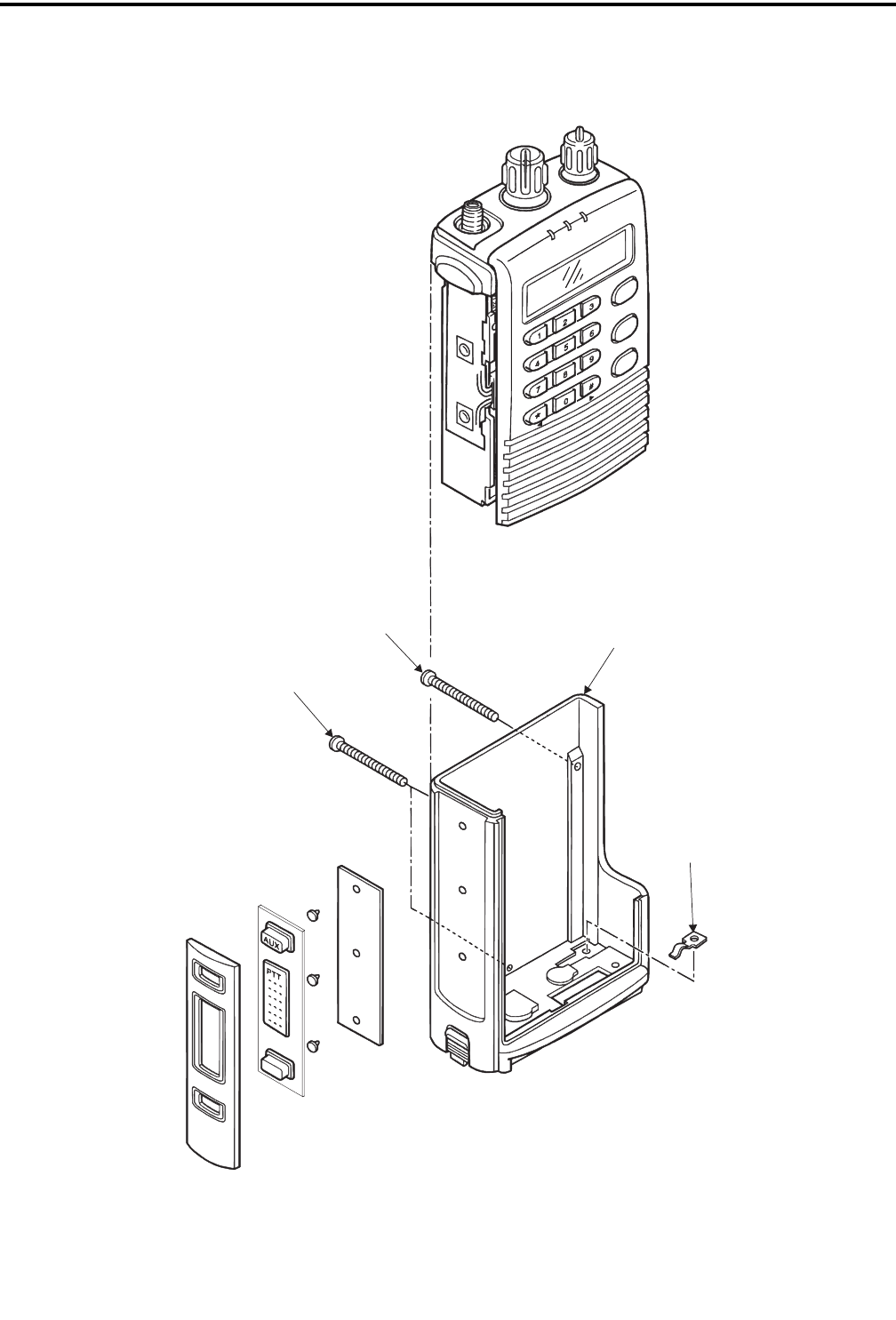
PARTS LIST
7-13 November 1999
Part No. 001-7780-500
FCN
MP18
MP35
MP35
MP25
ENT
CLR
F1
F2
F3
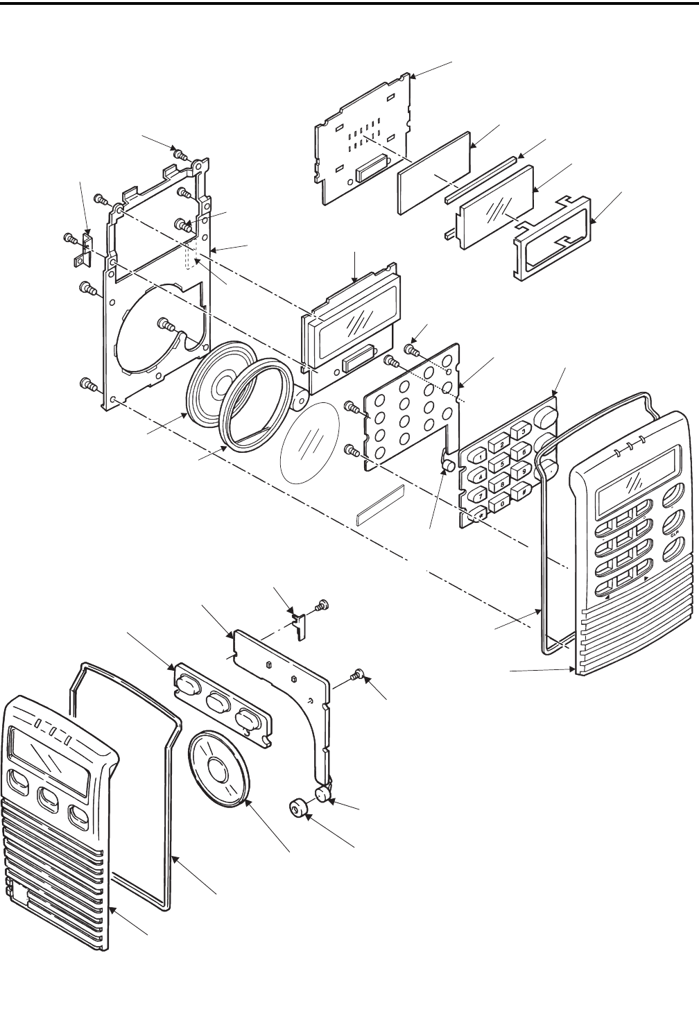
PARTS LIST
7-14
November 1999
Part No. 001-7780-500
ENT
Display Board
EP3
(Display) EP2
(Display)
DS6
(Display)
MP7
(Display)
MP4
(Display)
MP10 (4)
(Display)
Display Board
MP8
(Display)
MP12 (4)
Display)
MP9 (4)
(Display)
MP15
(Display)
SP1
(10-Key)
MP6
(Display)
MC1
(10-Key)
MP11
(Display)
MP1
(Display)
10-Key Board
F1
F3
MP16
(Display)
MP15
(Display)
MP10 (2)
(Display)
MC1
(3-Key Bd)
SP1
(3-key Bd)
MP11
(Display)
MP1
(Display)
MP4
(Display)
3-Key
Board
MP6
(Display)
10-KEY FRONT PANEL
3-KEY FRONT PANEL

PARTS LIST
7-15 November 1999
Part No. 001-7780-500
MP12
MP5
MP3
EP1
(Jack Assy)
MP4 (2)
(Jack Assy)
MP13
(Chassis) MP17
(Chassis)
J1/MP5
(Jack Assy)
MP16 (2)
(Chassis)
MP1
(Jack Assy)
MP2
(Jack Assy)
MP3
(Jack Assy)
EP2
(Logic Assy)
EP1
(Logic Board)
MP46
MP45
MP8
MP7
MP2
MP6
MP10
MP36 (4)
MP50
(Pad)
MP37 (2) EP1
(RF Board) MP4 (2)
J1
(Chassis)
MP49 MP1
EP1
(Chassis)
MP39 (4)
EP2
(Chassis)
MP47 (4)
MP3
(RF Unit)

PARTS LIST
7-16
November 1999
Part No. 001-7780-500
F1 MP33
MP27
MP28
MP29
MP34
MP22
MP26
MP30
MP18
MP24
MP23
MP32
MP34
MP27
MP32
MP52
(Sticker)
8-1 November 1999
Part No. 001-7780-500
SCHEMATIC DIAGRAMS AND COMPONENT LAYOUTS
SECTION 8 SCHEMATIC DIAGRAMS AND COMPONENT LAYOUTS
C4
Q1
C1
R8
R9
HC2
C5
C17
Q2
C2
C9
R1
R4
R5
HR1
C16
R13
R6
R15
R12
R2
HR2
R3
C15
R7
FIN
GND
PLLSK
PLLSO
PLLST
TA
LD
LO
GND
RF5V
LV
GND
PLL BOARD TOP VIEW
IC2 Q3
IC1
R16
HC1
C10 C12
GND
C14
C13 L1
C11
R10
C8 C7
CPV R14
PLL BOARD BOTTOM VIEW
SCHEMATIC DIAGRAMS AND COMPONENT LAYOUTS
8-2
November 1999
Part No. 001-7780-500
C7
C6 C4
C1
Q4
C10
C25
C9 C13
C14
HR1
C35
L2
C18
R9
C23
R21
D3
R16 R15
R14
HC1
R22
C30
C33
R24
R28R29
R27
C11
R4
Q2
C12
R5
R19
C20
C21 R17
R18
C29
GND
GND
RF5C
RF5V
CPV
VCOV
VCC
IC3
C15
Q3 X1 C24
C26
R23
R13
R20 C8
C3 C31
C2 HC2
C5
R2
IC1 IC2 D2
Q1
C19 HW1
R8
C16
C17
R7
W/N
FIOUT
GND
C32
IF5V
FIIN
R5V
GND
IFIN
GND
XTAL
RSSI
NOISE
DET
SQLC
R12 R26
R25
IF BOARD TOP VIEW
IF BOARD BOTTOM VIEW
November 1999
Part No. 001-7780-500
8-3 TRANSCEIVER BLOCK DIAGRAM
Rx Freq
Minus
45.225 MHz
First
Mixer
Q2
FI2 FI3 Q2
IF Amp
DET
RSSI
D13/
D14
Wide/Narrow
Band
Switch
Wide/Narrow
Band
Switch
Ceramic
Bandpass
Filter
Ceramic
Bandpass
Filter
Ceramic
Bandpass
Filter
FI6
FI5
Bandpass
Filter
Noise
Detector
Comparator
FI4 D15/
D16
RF Amp
Bandpas
Filter Bandpass
Filter
45.225 MHz
Bandpass
Filter
W/N
IF BOARD
RECEIVER
TRANSMITTER
SYNTHESIZER
PLL BOARD
RF UNIT
LOGIC UNIT
10-KEY OR 3-KEY
BOARD
DISPLAY
BOARD
SWITCH BOARD
ASSEMBLY
IC1 Q8 Q9 D7
Q5, Q6
Q7, D1,
D3, D11
FI7
L34,
D4
L13,
D5
Antenna Reverse
Power
Detector
Forward
Power
Detector
Low Pass
Filter
Antenna
Switch
Power
Control
Power
Amp Driver Predriver Tx/Rx Switch
16-Ohm
Speaker
SP1
SPE
IC306
Microcomputer
Microphone
MC1
W/N
RSSI
NOISE
RXDATA
SN RX
TXDATA
IC305,
Q3
RESET
XTAL
EXTAL 9.8304 MHz
X2
Q106,
Q107
Audio Amp
AMUT
LVCC
IC105,
IC106
Audio Amp
Audio Amp
IC104
EXT Terminal
(Accessory Connector)
DS6
LC Display
IC1
Display
Controller
Keyboard
PTT Sw
PTTIN
PLLST
DTMF SO
DTMF CK
Mic Mute Gate
IC204B
IC303
DTMF
Encoder
IC304
16K x 8
EEPROM
MSCK, MSO,
MSI, DPO TST Key S0-S3
Key R0-R3
QSEL 0-3
S1
Channel Sw
ULOCK
R117
Volume
Control
Mute
Gate
IC103
Expander
IC208
1/2
Bandpass
Filter
IC101
DC
Restoration
IC107
Data
Low Pass Filter
IC102
Q104
Data
Mute Gate
Q103
Bandwidth
Control
IC113A,
IC114
DC Restoration
IC112,
IC113B
Data
Low Pass Filter
Q108
Data
Mute Gate
Q201
BWC
Bandwidth
Control
IC206
A/B
Data
LP Filter
Test
Switch
IC203
IC210
Data Switch
Low Pass Filter
< 3 kHz
IC205 IC202B
Limiter High Pass Filter
> 300 Hz
IC202A
FI1 Q1
Q18
X3 Multiplier
X3
14.925 MHz
TCXO
IC4
Driver
Amp
Ref Freq
Set
R73
Second Mixer/Detector
Q12
Buffer
IC1 Synthesizer Chip
Phase
Detector
Reference
Counter
fR
fV
6.25
kHz
6.25
kHz
Prescaler
Div By
128/129
N
Counter
A
Counter
Charge
Pump
Q1, Q2 IC3
VCO Buffer
Q10, Q11
Q13
Lock
Detect
LD
PWR (Power Control)
LTR(Modulation Balance)
MOD (Modulation) IC201
Combiner
Digital Pot
T5V
DTMF
Mute
IC204A
IC208
1/2
Compressor
+5S
IC403
+3V Regulator
IC2
IC1
RF 5V
Regulator
VCO V Reg
Q1
CP V Reg
R13
Squelch
Level
Adjust
BWC
TXDATA
Smartnet
T/R Switch
IC110
T5V
Wide/Narrow Band Select
Noise
VCC
RECEIVE AUDIO PROCESSING
RECEIVE DATA PROCESSING
TRANSMIT DATA PROCESSING
TRANSMIT AUDIO PROCESSING
SMARTNET DATA PROCESSING
IC209
+5V
Audio
44.775 MHz Second Injection
450 kHz Second IF
SMARTNET
Data
Q406
+5S Regulator
Q405
T5V Regulator
Q404
R5V Regulator
R5V
T5V
+5V
+5L
VCC
+5V Regulator
IC402
L5V Regulator
IC401
R5C
T5C
S5C
Power Supplies
+5V Q403
Q402
LVCC Switch
VCC Switch
LVCC To
Audio Amps
7.5V
Battery
BAT
Power
On-Off Sw
BAT To PA IC1,
Pwr Ctrl Circuit
IC3
November 1999
Part No. 001-7780-500 8-4
IC1
FI7
HC6
C140
R77
D10
FI4
FI5
FI6
Q18
C104
IC3
HC15
X3
FI1
FI2
C49 R39 C50
C55
HC20
C122 C47
C40
Q6
R30
R29
R31 C42
R28
C41
R27
C54
C97 R75 R76
R74
R72
C96
R73
Q5
Q14
W1
L33
L26
L25 C52
HC12
C91
IC4
C95
C94 L30
C133
C134
C132
L28
C128
R87
C131
C130
R86
C129
L27
RF5V
RF5C
GND
VCC
VCOV
R41
R42
R43
C119
C60
C88
CPV
C53
R36 C48
R37
C137
J1
MIC
JACK
HC1
C103
C84
R66
C102
C101
C100
R68
R67
C83
C107
Q12
J1
FIN
GND
PLLSK
PLLSO
PLLST
LOCKUP
LD
LO
GND
RF5V
LV
GND
D9
C136
C98
L23
Q13
Q11
C93
R45
C65
R44 R46
D7
C75
Q10
C106
C105
R101
FI3
C126
R98
HC7
D13 R92
C29
R102
HC2
HC5
C27
R91
D15 R96
L13
L34
C35
C34
R21
C36
R22
R25
C38
C37
R23
C33
C1
C2
R83
C63
C58
R82 C62
L15
L24
Q8
Q16
Q9
R80
HC17
HC14
C43
R24
C44
R32
R33
Q7
C57
HC13
HW2
W3
R63
R64 C89
C85
D6
C64
L16
C90
R59
R58
R65
C81
L22
C82
R62
R61
HC10
PWR
TMUT
T5V
LTR
MOD
+5V
LOCKUP
ULOCK
GND
GND
BATT
BATT
BATT
BATT
BATT
R5V
DET
NOISE
RSSI
W/N
PLLST
PLLSO
PLLSK
RF5C
GND
VCC
VCC
GND
GND
GND
C108
C109
HC16
HC18
C139
C26 C76
R53
C78
C77
R54
L20
R56
R60 R57
C80
R55
R85
C127
C79
L19
R97
R51
C10
R69 C68
C67
C71
C70
R47
C69
R48
L29
R79
C22
C24
C74
C114
C73
R52
R50
C66
L17
C121
C120
R49
C124
Q17
C72
L12
C23
R12
HC8
C28 D14
R94
C135
R93
R103
L10
C15
C18
W4
R99
C19
R78
C117
C25
R5
R4
W5
R6
C20
C17
C16
L8
Q2
C12
W6
R11
R10
R9
L11
R7
C13
C14
L6
L7
C11
C125
C59
L9
C7
HR1
Q1
C5
L5
C9
R1
C8
C4
R3
R2
C138
L32
D16
R95
HC3
Q20
Q21
Q19
R104
L14
C31
R20
D4
D5
L1
D1
L2
D3
D2
IC2
R26
R35
C46
C111
C32
C45
R34
HC9
D11
C30
W/N
FIOUT
GND
IF5V
FIIN
R5V
GND
IFIN
R5V
GND
INFIN
GND
XTAL
RSSI
NOISE
DET
C112
TO PLL BOARD
TO IF BOARD
TO LOGIC BOARD
RF BOARD TOP VIEWRF BOARD BOTTOM VIEW
November 1999
Part No. 001-7780-500
PWR ADJUST
0.047
C119
33P
C60
PWR
TMUT
T5V
BATT
MOD
LTR
TA
33P
C102
33P
C101
33P
C100
33P
C93
C
HC1
+5V
PWR
PLLSK
ULOCK
PLLST
LTR
BATT
PLLSO
MOD
T5V
TMUT
33P
C107
33P
C106
33P
C105
33P
C104
33P
C112
SQLC
AXK6S30645P
J1
30
29
28
27
26
25
24
23
22
21
20
19
18
17
16 15
14
13
12
11
10
9
8
7
6
5
4
3
2
1
C
HC10
RF5C
VCC
PLLSK
PLLSO
PLLST
W/N
RSSI
NOISE
DET
R5V
33P
C103
15P
C11
2.2U
L1
MB15A02PFV
IC1
6
1
R
5
1
P
4
1
T
U
O
F
3
1
C
N
2
1
C
F
1
1
E
L
0
1
A
T
A
D
9
K
C
O
L
C
8
N
I
F
7
D
L
6
D
N
G
5
O
D
4
C
C
V
3
P
V
2
T
U
O
C
S
O
1
N
I
C
S
O
0.001
C10
0.047
C12
33P
C13
10K
R10
C
HC18
C
HC16
33P
C108
33P
C109
PLL BOARD
470
R14
33P
C9
0.047
C14
10 10V
C1
33P
C2
33P
C8
33P
C7
15P
C136
2.2u
L30
47K
R67
50K
R73
100K
R69
100K
R75
22K
R76
CR-626
X3
4VCC
3OUT 2
GND
1
VCON
2SA1576
Q13
33P
C94
0.1
C95
33P
C131
33P
C133
5P
C132
0.01
C128
2SC4215
Q18
TC75S54F
IC4
5
4
2
3
1
33P
C97
0.047
C91
0.1
C89
33P
C90
MA2S111
D9
100K
R74
100K
R72
100K
R68
33P
C120
33P
C96
0.33
L28
3.3K
R80
DTC144EE
Q17
2SA1577
Q16
0.1
C124
33P
C121
33P
C125 220K
R35
10K
R34
0.1
C45
100K
R32
100
R37
220
R36
33P
C48
2SC4081
Q5
33P
C137
47K
R39
100K
R82
33P
C50
2SB1132 Q
Q6
33P
C46
NJM2904V
IC2B
76
5
33P
C47
27K
R33
1.8K
R30
100K
R27
56K
R28
1
C122
47K
R24
C
HC14
0.047
C40
33K
R29
470P
C44
33P
C49
NJM2904V
IC2A
8
4
1
2
3
33P
C42
3.3K
R31
470P
C41
100K
R26
33P
C43
1K
R21
470P
C34
5P
C33
33P
C37
1K
R22
10K
R23
HSM88AS
D4
4P
C35
33P
C38
10K
R25
15P
C36
HSM88AS
D5
(CHASSIS UNIT)
2.7K
R45 22
R83
22
R44
BLM21P300S
L25
82
R20
33P
C63
4.7
C57
4.7
C53
C
HC12
C
HC9
10
R46
33P
C67
T5V
BLM21P300S
L24
BLM21P300S
L26
33P
C52
MA2S111
D6
1u
L16
33P
C31
33P
C65
33P
C59
33P
C58
33P
C111
TMUT
BATT
33P
C32
UMD3
Q7
1
2
34
5
6
33P
C68
33P
C64
3P
C134
33P
C77
2.7K
R79
4.7K
R50
56
R52
0.047
C74
15
R47
0.047
C114
33P
C76
470P
C71
1.2K
R49
4.7K
R48
33P
C70
33P
C73 33P
C69
6.8K
R64
33P
C81
3.9K
R55
C
HC15
1.8K
R65
470K
R87
1.2K
R86
33P
C84
33P
C82
15n
L22
0.01
C130
0.01
C129
0.33
L27
33P
C79
56
R66
2SC4228
Q12
NVCO-SM-838
IC3
8
7
6
54
3
2
1
820
R63
15
R59
1.5P
C83
33P
C85
270
R62
18
R61
270
R60
15
R58
6.8K
R15
1.2K
R8
C
HC1
C
HC2
0.1
C17
TC7S66FU
IC2 45
321
DTC144EE
Q3
270
R16
2.7K
R9
100
R7
1.5
C5
0.1
C4
33P
C98
ERJ3GE-JPW
HW2
ERJ3GE-JPW
W3
C
HC13
1u
L23
1.8K
R13
4.7K
R12
R
HR2
100
R3
2SC4081
Q2
2SA1576
Q1
150
R6
1.5K
R5
2.2K
R2
3.3K
R4
5.6K
R1
12P
C16
18P
C15
R
HR1
10K
R101
0.1
C139
W/N
VCC
R5V
NOISE
RSSI
R5V
NAR
C
HC5
WIDE
DTC144EE
Q21
DTA144EE
Q19
DTA144EE
Q20
MA2S111
D10
XTAL
C
HC7
C
HC6
15K
R93
0.1
C28
C
HC2
C
HC3
CPV
VCOV
R5V
RF5V
NAR
10K
R77
XP4601
Q14
1
2
34
5
6
33P
C88
2.7K
R103
MA2S077
D15
MA2S077
D16
MA2S077
D14
MA2S077
D13
CFUM450F
FI5
43
21
10
R92
SFPC450E
FI4 21
3
SFPC450G
FI6 21
3
10K
R94 15K
R96
12n
L20
0.01
C135
22K
R95
0.1
C27
560
R54
12K
R91
56
R85
2.2K
R56
33P
C127
33P
C80
5P
C78
2SC4228
Q11
15
R57
6.8K
R102
7P
C117
3.9n
L29
2.2K
R78
4.7K
R51
1K
R12
2SC3357
Q9
2P
C75
1K
R97
10n
L12
12n
L19
3.5P
C23
0.1
C29
39K
R53
3.5P
C24
33P
C22
2SC4228
Q10
MA78
D7
33P
C72
33P
C25
C-TRIMM
HC20
UM9401F
D11
33n
L11
ERJ3GE-JPW
W6
39n
L14
10P
C55
33P
C54
5P
C62
2.5P
C66
6.8n
L17
270
R9
8.2n
L15
470
R43
470
R41
10
R42
18
R10
270
R11
IN
IC1
CP1
OUT
CP5
VCC2
CP3
VCC3
CP4
VCC1
CP2
2SC3357
Q8
ANT JACK
J1
2
1
0.5P
C140
W1
UM9401F
D3
0.3P
C1
DCS3220-09
L34
MA77
D2 c
HC17
4P
C2
8.8n
L1 8.8n
L2
GLP-802-2
FI7
2
1
G
1
1
G
0
1
C
N
9
C
N
8
G
7
G
6
T
U
O
5
G
4
G
3
G
2
G
1
N
I
33P
C30
MA77
D1
DCS3220-09
L13
560
R104
4.7K
R2
10n
L32
15P
C138
33P
C4
0.047
C8
1.8K
R3
EZFU860AM81T
FI1
33P
C5
33K
R5
180
R7
18n
L6
3P
C7
56
R6
2SC5015
Q1
8.2n
L33
ERJ3GE-JPW
W5
39n
L8
68n
L7
0.18u
L10
18P
C15
33P
C13
1P
C11
33P
C9
56K
R4
560
R1
EZFU860BM81T
FI2
3SK177 U72
Q2
R
HR1
10n
L5
33P
C12
33P
C10
0.01
C1412P
C26
0.01
C18
470
R99
ERJ3GE-JPW
W4
0.5P
C126
390
R98
33P
C16
0.01
C17
4P
C19
FL-295
FI3
0.47U
L9
0.01
C20
ERJ3GE-JPW
HW1 WIDE
0.001
C19
DTC144EE
Q3
33P
C26
C
HC8
IF BOARD
33P
C35
0.001
C24
0.01
C30
330
R22
0.001
C25
FIIN
FIOUT
IF5V
XTAL
NOISE
RSSI
IF5V
R5V
C
HC2
10
C7
4.7
C1
MA8056
D2
2SC4081
Q1
4.7K
R2
0.001
C2
0.001
C5
10
C6
SQLC
DET
RF5C
10
C4
0.047
C3
0.1
C31
0.1
C8
TK11360BM
IC2
3N.BYPASS
6
VIN 5
GND 4
VOUT
2GND
1CONT
TK11350BM
IC1
3N.BYPASS
6
VIN 5
GND 4
VOUT
2GND
1CONT
100K
R25
6.8K
R28
2.2K
R27
100
R16
6.8K
R12
C
HC1
0.001
C34
330K
R17
47K
R15
2.2K
R26
1.2K
R24
220P
C21
220P
C20 470K
R19
1K
R18
100K
R14
47K
R13
UMG2
Q4
45
123
0.047
C33
NOISE
RSSI
0.1
C18
0.1
C29
1.5K
R23
R
HR1
TA31136FN
IC3
16
MIXIN 15
GND 14
N-REC 13
N-DET 12
RSSI 11
IFOUT 10
QUAD 9
AFOUT
8FILIN
7FILOUT
6DEC
5IFIN
4VCC
3MIXOUT
2OSCOUT
1OSCIN 0.56U
L2
0.001
C23
330
R9
CDBCA450CX24
X1
0.001
C16
820P
C32
2.7K
R8
2.2K
R7
68P
C17
10K
R20
4.7
C15
56
R4
0.01
C13
0.01
C14
18P
C10
0.01
C11
0.01
C12
180
R5
MA2S728
D3
2SK882 GR
Q2
100K
R21
0.01
C9
IF AMP
LIMITER/SECOND MIXER/DETECTOR
SQUELCH
Squelch
Adjust
CPV REGULATOR
RF5V REGULATOR
VCOV
CRYSTAL
FILTER
FIRST
MIXER
BANDPASS
FILTER
RF AMP
BANDPASS
FILTER
RECEIVER
HARMONIC FILTER
DIRECTIONAL
COUPLER
Forward
Reverse
RF POWER MODULE
DRIVER
PREDRIVER
TRANSMITTER
ANTENNA
SWITCH
POWER CONTROL
Rx Freq Minus 45.225 MHz
TX/RX SWITCH
BUFFER
BUFFER
450 kHz CERAMIC BANDPASS FILTERS
VCO
CTRL
OUT
MOD
SYNTHESIZER
ACTIVE FILTER
VCO CONTROL
SYNTHESIZER
TA SWITCH
CHARGE PUMP
LOOP FILTER
TO
LOGIC
UNIT
14.925 MHz TCXO
TRIPLER
44.775 MHz SECOND INJECTION
LOCK
DETECT
BUFFER
FREQ ADJ
MODULATION AMPLIFIER
TX SWITCH
I
IO
O
RF BOARD SCHEMATIC
8-5
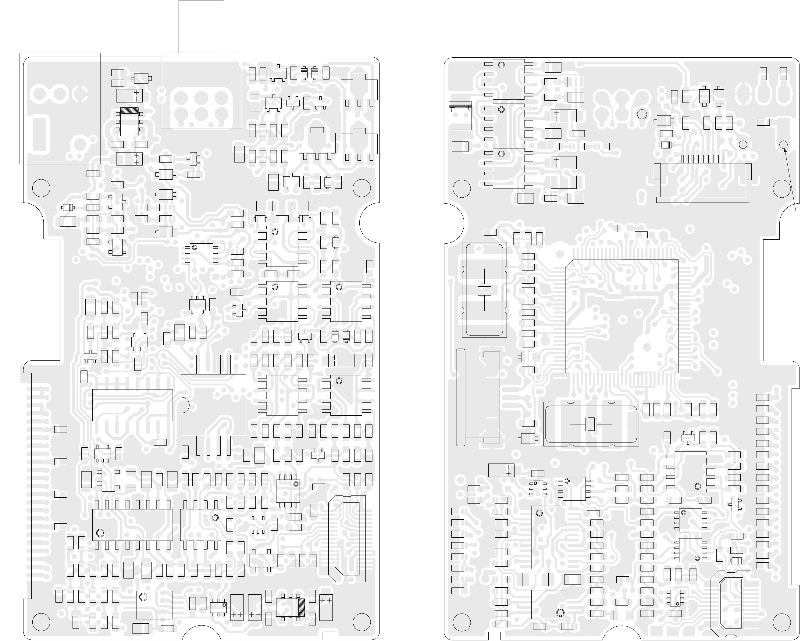
November 1999
Part No. 001-7780-500
1
5
TO
ACCESSORY
JACK
TO PTT BOARD
1
10 11
20
IC209
IC205
IC210
J3
X2
C304
C305
C303
C123
IC104
IC105
IC106
C401
D403
D311
R163
R335
C419
C36
C32
J2
HC2
HC1
R332
R309
R308
R333
C55
C54
C216
C218
R239
IC206
IC203
IC204
W4
W5
C205
R211
Q405
J4
IC306
Q406
X1
C433
C444
C443
C450
C437
C436
D309
W6
R167
PTT OUT
PTT IN
RX IN
RX OUT
EXTDC
OPTB
AMUTI
AMUTO
BEEPO
GND
GND
TX OUT
TX IN
CLR/CODE
T5C
OP1
OP2
OP3
OP4
SW BATT
C418
R207
R215
R214
R213
C229
R254
R212
C207
R240
C209
R216
C16
R220
C210
R221
C211
R225
R244
R226
C45
R227
W12
C214
C226
R222
C208
R223
C44
C213
R224
C212
R243
C4
C23
C15
C1
C30
C31
C2
C7
C5
C3
C25
C24
C6
C423 C422
D308
R323
R301
R249
R302
R232
R235
C215
R236
R231
C43
C219
C217
R238
R237
C435
C438
C439
C440
C449
C448
C447
C454
C430
C431
Q201
Q111
R320
D307
R329
R328
C22
C21
R325
R324
R322
HR1
W10
W9
C137
C118
R127
C111
C138
W8
R408
C402
D313
R337
D310
C113
C136
C142
R145
C139
C140
R132
R131
C121
C122
C141
C403
AUXB
MICE
GND
FCNB
GND
R241
C11
PTT
EXTMIC
TxD
RxD
LVcc
GND
PSW
RESET
AFO
1
9
To DC Power
Flex Circuit
R404
D401
D402
R403
R164
Q403
Q402
Q106
C144
D103
R148
C301
R303
R304
D301 R306
C306
C53
IC107
R140
R139
D102
D101
R141
C52
C17
IC102
R136
C127
R135
C124
R134
C125
C126
R137
C128
R133
C14
C12
C10
J1
C409
C410
C411
C8
C13
R402
R401 C143
R146
C110
R124
C116
R147
C145
R149
R118
R119
R120
C115
IC114
IC113
R159
C155
R158
C156
R157
R156
C153
R154
R153
IC112
C152
R152
C151
R155
C154
C150
R150
R151
C227
C225
R101
R250
R104
IC110
R102
R103
R106
R165
R107
C20
C9
R228
C421
C412
C413
C415
C416
C48
C106
R108
C105
R109
C108
R142
C104
C101
C103
IC101
C102
C51
R105
R111
R110
C18
C107
IC303
R248
R406
R407
C414
C49
Q108
IC309
Q302
IC401
Q301 IC305
R338
R339
R168
R169
R125
C109
C134 C159
R113
R116
R112
HR2
IC304
C26
W11
R210
C224
C222
IC403
IC208
R143
R166
C130
C223
R245
R205 C203
IC202
R204
R253
C46
C432
R203
R206
C201
C202
R202
R201
R247
R246
C206
C228
C456
W7
C406
C404
C405
C420
C408
C407
R326
D312
C29
C33
R315
R314
D302 C28 R316
D305
Q401
Q102 Q105
Q109
Q107
C157
C158
R317
R321
R330
R331
R170
R162
R161
Q104
IC115
Q112
D306
HD1
R318
C27
HC3
R311
C307
R310
R313
R312
R319
D104
R160
Q103
HC4
C19
IC103
Q101
C446
C441
C434
C451 Q110
IC201
R252
R251
IC402
Q404
R208
C204
SPE
SPE
SP
SP
L5V
MSO
MSCK
DISST
DISEN
KEYSO
KEYS1
KEYS2
KEYS3
KEYRO
KEYR1
KEYR2
KEYR3
TXLED
DSYLED
BATLED
BKLED
GND
MICE
MIC
GND
GND
PWR
TMUT
T5V
LTR
MOD
+5V
TA
ULOCK
GND
GND
BATT
BATT
BATT
BATT
BATT
R5V
DET
NOISE
RSSI
W/N
PLLST
PLLSO
PLLSK
RF5C
GND
Vcc
Vcc
GND
GND
GND
C129
R336
S1
R117
D105
130
15 16
TO DISPLAY UNIT
TO RF UNIT
Channel Switch
On-Off Volume Control
LOGICBOARDTOPVIEW
LOGIC BOARD TOP VIEW
8-6
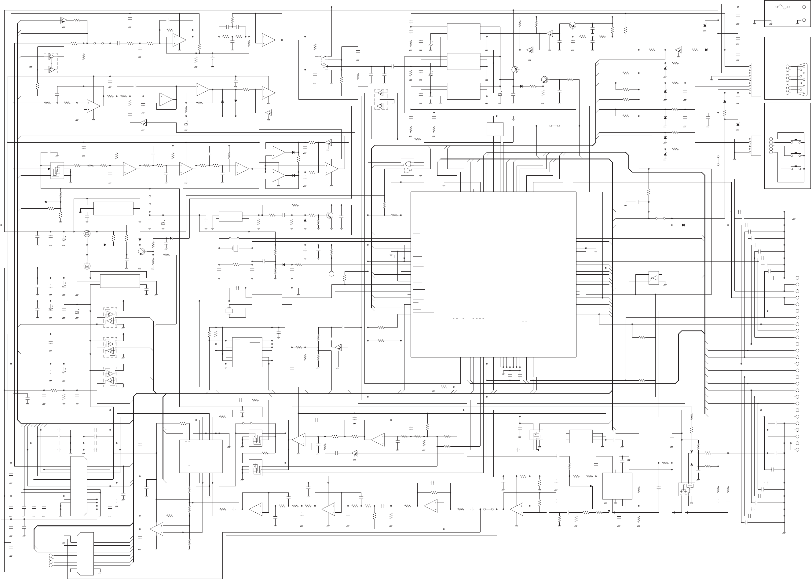
November 1999
Part No. 001-7780-500
TX_IN
TX_OUT
SW_BATT
39K
R202
39K
R201
TC4W66FU
IC204
5876
4321
0.1
C206 0.1
C228
33PC450
33PC443
33PC435
33PC436
33PC434
33PC437
33PC451
5.6K
R166
18K
R143
100
R245
1
C204
MC33111D
IC208
6
1
C
C
V
5
1
O
E
4
1
I
E
3
1
C
N
2
1
M
E
1
1
F
E
0
1
2
O
I
9
2
I
I
8
T
P
7
1
I
I
6
1
O
I
5
F
C
4
M
C
3
I
C
2
O
C
1
D
N
G
1.8K
R246
33K
R207
33K
R339
22K
R338
1
C222
1
C223
1K
R247
0.0047
C201
0.0047
C202
220K
R205
47K
R204
0.0047
C203
33P
C229
1M
R213
5.6K
R211
56K
R208
1K
R214
NJM2904V
IC202A
8
4
1
2
3
ERJ3GE-JPW
W5
0.0047
C205
TX_IN
TX_OUT
NJM2904V
IC202B
7
6
5
0.1
C48
820
R215
0.0033
C210
3.3K
R222
39K
R220
470K
R216
+5V
TEST
56P
C212
0.0047
C213
0.047
C208
560P
C211
150K
R224
68K
R223 82K
R221
1
C209
NJM2904V
IC205A
8
4
1
2
3
0.1
C44
10K
R227
10K
R226
4.7K
R228 5.6K
R225
TC75S54F
IC201
5
4
2
3
1
0.1
C45 MSCK
1
C214
33P
C9
10K
R244
NJM2904V
IC205B
7
6
5
SQLC
TA
33P
C10 33P
C8
33P
C4
33P
C2
33P
C1
AXK520145P
J4
20
19
18
17
16
15
14
13
12
1110
9
8
7
6
5
4
3
2
1
OP4CP204
OP3CP203
OP1
CP201 OP2CP202
0.1
C31
0.1
C30
BEEPO
AMUTO
AMUTI
RF5C
EXTDC
OPTB
RX_IN
RX_OUT
PTT_IN
PTT_OUT
T5C
CLR/CODE
33P
C13
33P
C14
BATT
33P
C7
33P
C6
VCC
+5V
MOD
LTR
W/N
RSSI
ULOCK
PLLST
PLLSK
PLLSO
100K
R407
200K
R406
AXK5S30245P
J1
30
29
28
27
26
25
24
23
22
21
20
19
18
17
16 15
14
13
12
11
10
9
8
7
6
5
4
3
2
1
0.22
C414
33P
C12
33PC20
33PC11
33PC25
33PC23
33PC15
33P
C3
33P
C5
33PC24
T5V
PWR
NOISE
0.1
C49
TMUTDET
R5V
BATIN
0.1
C225
ERJ3GE-JPW
W1268K
R241
TC4W53FU
IC210
8
7
6
5
4
3
2
1
4.7
C226
1
C227
10K
R249
50k
AD8403
IC209
4
2
1
B
3
2
1
A
2
2
1
W
1
2
1
D
N
G
A
0
2
3
B
9
1
3
A
8
1
3
W
7
1
3
D
N
G
A
6
1
D
D
V
5
1
S
R
4
1
K
L
C
3
1
O
D
S
2
1
I
D
S
1
1
S
C
0
1
N
D
H
S
9
D
N
G
D
8
4
W
7
4
A
6
4
B
5
4
D
N
G
A
4
2
W
3
2
A
2
2
B
1
2
D
N
G
A
MSO
+5S
10K
R243
DPOTST
R5C
TC4W53FU
IC203
8
7
6
54
3
2
1
MC33172D
IC206B
7
6
5
10K
R240
0.0022
C218
330K
R239
+5L
VOL_IN
47K
R238
MC33172D
IC206A
8
4
1
2
3
DTC144EE
Q201
R
T
_
N
S
+5S
BWC
DTMF
L5V
47K
R237
0.1
C43
0.0033
C217
0.1
C219
47K
R170
27K
R232
1
C134
TC7S66FU
IC103
45
321
100K
R236
0.01
C26
RXDATA
100K
R302
470K
R301
100K
R235
0.01
C216
0.01
C215 27K
R231
0.1
C108
+5V
10K
R142
S-81230SG
IC403
5NC
4NC 3
VOUT
2
VIN
1
GND
470K
R210
1
C130
+5L
1
C456
DTMFMT
PT
+5S
L5V
DTMF
MMUTE
RMUTE
100K
R333
1
C224
220K
R254
1.2M
R212
2.2K
R253
1
C46
2.7K
R206
0.01
C16
33P
C444
33P
C433
2.7K
R203
33P
C432
CP11
CP10
CP9
CP8
CP7
CP6
CP5
CP4
CP3
CP2
CP1
MIC
MICE
BKLED
BATLED
BSYLED
TXLED
KEYR3
KEYR2
KEYR1
BSYLED
+5L +5L
MSCK
MSO
L5V
MSO
MSCK
CP26
CP25
CP24
CP23
CP22
CP21
CP20
CP19
CP18
CP17
CP16
CP15
CP14
CP13
CP12
SPE
SP
KEYR0
KEYS3
KEYS2
KEYS1
KEYS0
DISEN
DISST
NPSPAC
SQLC
TA
100K
R332
MSCK
I
S
M
L5V
R5C
BEEP
T5C
TMUT
ULOCK
PLLST
X
R
_
N
S
C
D
T
X
E
O
S
M
0.01
C55
0.1
C54
C
E
R
P
X
T
I
S
S
R
V
5
L
N
I
T
A
B
E
T
U
M
M
E
S
I
O
N
C
W
B
A
T
A
D
X
R
A
T
A
D
X
T
T
S
E
T
0
R
Y
E
K
1
R
Y
E
K
2
R
Y
E
K
3
R
Y
E
K
T
S
T
O
P
D
10K
R112
560K
R116
R
HR2
47K
R113
0.01
C159
0.1
C207
0.01
C109
100K
R328
100K
R329
O
P
E
E
B
DTC144EE
Q101
OFFREQI
QSEL0I
DTMFCK
FCN
AUX
0.01
C19
O
S
M
K
C
S
M
T
M
F
M
T
D
P
E
E
B
DTMFSO
TXD
OFFRQ 3.579MHz
CR-563
X1
S
C
P
E
E
10K
R308
10K
R309
X25128
IC304
16
VCC 15
HOLD 14
NC 13
NC 12
NC 11
NC 10
SCK 9
SI
8VSS
7WP
6NC
5NC
4NC
3NC
2SO
1CS
I
S
M
0.1
C421
T5C
S5C
PCD3312CT
IC303
8
SDA 7
SCL 6
A0 5
TONE
4OSCO
3OSCI
2VDD
1VSS
0.01
C18
+5V
RF5C 0.001
C422
0.001
C416
R5V
T5V
+5S
4.7
C412
UMD6
Q406
1
2
3
4
5
6
UMD6
Q405
1
2
34
5
6
UMD6
Q404
1
2
34
5
6
4.7
C423
4.7
C415
0.001
C418
33P
C413
0.001
C410
33P
C411
4.7
C409
6.8K
R250
10K
R252
12K
R251
BATT
2SJ316
Q403
VCC
TXDATA
LVCC
0.1
C420
33P
C406
0.001
C405
4.7
C404 100K
R403
MA2S111
D401
TK11250BM
IC402
3
N.BYPASS
6VIN
5GND
4VOUT
2
GND
1
CONT
TK11250BM
IC401
3N.BYPASS
6
VIN 5
GND 4
VOUT
2GND
1CONT
2SJ316Q402
1K
R408
2SC4081
Q401
MA2S111
D402
18K
R401
MA8039
D403
ERJ3GE-JPW
W7
R
HR1
15P
C303 18P
C304
9.8304MHz
CR-635
X2
ERJ3GE-JPW
W10
10K
R402
T5V
PSW
S-80842ALNP
IC305
4VSS
3NC 2
VDD
1
OUT
0.1
C301
33P
C401
1
C403
100K
R404
100K
R310
33P
C408
4.7
C407
0.01
C22
0.1
C21
18K
R303
27P
C305 MA2S077
D301
1K
R306
0.1
C306
12K
R304
10K
R312
C
HC3
2SC4081
Q301
100K
R330
CSHIFT
10K
R248
MD1
NMI
100K
R322
L5V
0.22
C307
1K
R311
100K
R321
MA2S111
D302
220K
R314
220K
R315
470K
R313
RESET
RXD
HD6432144FA20
IC306
9
9
1
K
C
S
/
5
Q
R
I
/
6
8
P
8
9
1
D
X
R
/
4
Q
R
I
/
5
8
P
7
9
1
D
X
T
/
3
Q
R
I
/
4
8
P
6
9
3
8
P
5
9
2
8
P
3
9
0
8
P
4
9
1
8
P
2
9
S
S
V
1
9
0
D
/
0
B
P
0
9
1
D
/
1
B
P
9
8
5
1
D
/
7
3
P
8
8
4
1
D
/
6
3
P
6
8
3
1
D
/
5
3
P
7
8
2
1
D
/
4
3
P
5
8
1
1
D
/
3
3
P
4
8
0
1
D
/
2
3
P
3
8
9
D
/
1
3
P
2
8
8
D
/
0
3
P
1
8
2
D
/
2
B
P
0
8
3
D
/
3
B
P
9
7
0
A
/
0
1
P
74
P15/A5 73
P16/A6 72
P17/A7 71
VSS 70
VSS 69
PB4/D4 68
PB5/D5 67
P20/A8 66
P21/A9 65
P22/A10 64
P23/A11 63
P24/A12 62
P25/A13 61
P26/A14 60
P27/A15 59
VCC 58
PB6/D6 57
PB7/D7 56
P47/PWX1 55
P46/PWX0 54
P45/TMRI1 53
P44/TMO1 52
P43/TMCI1 51
P42/TMRIO/SCK2
0
5
0
O
M
T
/
2
D
X
R
/
D
X
R
R
I
9
4
I
C
M
I
/
2
D
X
T
/
D
X
T
R
I
8
4
6
1
A
/
8
N
I
C
/
8
N
I
K
7
4
7
1
A
/
9
N
I
C
/
9
N
I
K
6
4
S
S
V
A
5
4
7
7
P
/
7
N
A
/
1
A
D
4
4
6
7
P
/
6
N
A
/
0
A
D
3
4
5
7
P
/
5
N
A
2
4
4
7
P
/
4
N
A
1
4
3
7
P
/
3
N
A
0
4
2
7
P
/
2
N
A
9
3
1
7
P
/
1
N
A
8
3
0
7
P
/
0
N
A
7
3
C
C
V
A
6
3
F
E
R
V
A
5
3
7
N
I
C
/
7
N
I
K
/
7
Q
R
I
4
3
B
O
T
F
/
6
N
I
C
/
6
N
I
K
3
3
D
I
T
F
/
5
N
I
C
/
5
N
I
K
2
3
C
I
T
F
/
4
N
I
C
/
4
N
I
K
1
3
8
1
A
/
0
1
N
I
C
/
0
1
N
I
K
0
3
9
1
A
/
1
1
N
I
C
/
1
1
N
I
K
9
2
B
I
T
F
/
3
N
I
C
/
3
N
I
K
8
2
2
N
I
C
/
2
N
I
K
/
Y
I
M
T
7
2
A
O
T
F
/
1
N
I
C
/
1
N
I
K
6
2
I
C
T
F
/
0
N
I
C
/
0
N
I
K
25 ADTRG/IRQ2/LWR
24 IRQ1/P91
23 IRQ0/P92
22 RD/P93
21 KIN12/CIN12/A20
20 KIN13/CIN13/A21
19 HWR/P94
18 IOS/AS/P95
17 EXCL/P96
16 WAIT/P97
15 VSS
14 TXD0/P50
13 RXD0/P51
12 SCK0/P52
11 KIN14/CIN14/A22
10 KIN15/CIN15/A23
9VCC
8STBY
7NMI
6MD0
5MD1
4FWE
3EXTAL
2XTAL
8
7
1
A
/
1
1
P
75
P14/A4
7
7
2
A
/
2
1
P
6
7
3
A
/
3
1
P
0
0
1
O
S
E
R
1RES
OFFRQ
0.047
C308
TC7S04FU
IC115
4
5
3
2
1
100K
R331
ERJ3GE-JPW
W6
PTTIN
PTT_IN
PTT_OUT
W/N
PT
PLLSO
PLLSK
DISST
DISEN
KEYS3
KEYS2
KEYS1
MA2S111
D309
33PC447
33PC448
33PC449
33P
C446
CP27
33P
C431
33P
C454
33PC438
33PC439
33PC440
33PC441
33PC430
FCNB
MICE
AUXB
PTT
EXTMIC
ERJ3GE-JPW
W11
33P
C28
TXD
MA8056
D313
470
R337
MA2S111
D310
33P
C27
33P
C33
33P
C32
EXTMIC
PTT
FCNB
AUXB
MICE
GND
GND
470
R323
470
R320
470
R318
52207-0590
J3
5
4
3
2
1
TXD
XTXD
2.2K
R147
1
C145
100K
R319
ERJ3GE-JPW
W8
O
T
U
M
A
I
T
U
M
A
100K
R324
100K
R317
MA8056
D307
MA8056
D308
FCN
AUX
MA8056
D306
MA8056
D305
KEYS0
47K
R169
2.7
R131
0.01
C142
2.7
R132
0.1
C121
1
C141
EC10SP16-51
S1
6
8
5
4
4
2
3
1
2
2
C
1
1
C
I
Q
E
R
F
F
O
TC7W32FU
IC309
8
7
6
54
3
2
1
R
T
_
N
SBATLED
OPTB
CLR/CODE
T
U
M
A
E
T
U
M
R
T
M
F
M
T
D
C
5
S
PTTIN S
C
P
E
E
33P
C144
0
L
E
S
Q
1
L
E
S
Q
2
L
E
S
Q
3
L
E
S
Q
D
E
L
X
T
D
E
L
Y
S
BBKLED
XTXD
XRXD
33
C123
0.1
C122
UMG2
Q112
4
51
2
3
MC33172D
IC107A
8
4
1
2
3
SN_RX
BWC
+5S
T5V
RXDATA
PSW
DTC144EE
Q108
DTC144EE
Q104
MC33172D
IC114A
8
4
1
2
3
1
C158
MC33172D
IC113A
8
4
1
2
3QSEL0I
33K
R162
33K
R161
1
C157
MA2S111
D104
15K
R160
MA2S111
D105
MC33172D
IC114B
7
6
5
22K
R159
22K
R156
0.0033
C126
MC33172D
IC113B
7
6
5
MC33172D
IC112B
7
6
5
0.0068
C156
0.022
C155
0.0022
C154
0.047
C153
15K
R158
2K
R157
20K
R155
3.3K
R154
MA2S111
D102
MC33172D
IC112A
8
4
1
2
3
MA2S111
D101
100K
R140 560K
R139
330K
R137
DTC144EE
Q103
100K
R141
MC33172D
IC102B
7
6
5
4.7
C129
0.0022
C128
33K
R153
+5V
MC33172D
IC102A
8
4
1
2
3
C
HC4 0.01
C17
TC4W53FU
IC110
8
7
6
54
3
2
1
DET
SN_RX
SN_TR
+5S
0.01
C152
10K
R152
1K
R151
1K
R150
0.01
C124
47K
R136
100K
R133 47K
R135
0.01
C125
100K
R134
100K
R102
56K
R167
DTC144EE
Q111
NPSPAC
150K
R101
47K
R165
UMG2
Q110
4
5
1
2
3
W/N
0.01
C101
+5S
BATT
LVCC
R5V
RX_IN
RX_OUT
ERJ3GE-JPW
W4
0.1
C52
470P
C102
0.001
C103
150K
R110
560K
R108
5.6K
R109
0.01
C105
0.039
C104
390K
R106
0.1
C51
MC33172D
IC101A
8
4
1
2
3
0.1
C127
0.01
C106
0.1
C53
120K
R105
MC33172D
IC107B
7
6
5
100K
R111
1
C107
27K
R107
47K
R104
47K
R103
2.7K
R168
10K
RV-283
R117
1K
R125
0.1
C136
2.2K
R163
C
HC2
C
HC1
MC33172D
IC101B
7
6
5
33P
C113
33P
C419
1.2
R148
100K
R164
DTC144EE
Q109
4.7
C111
2.7
R127
10K
R145
MA2S111
D103
2SB798
Q106
4.7
C138
1
C139
1
C137
4.7u
C140
TDA7233D
IC104
8+INPUT
7-INPUT
6SVR
5OUTPUT 4
+VS 3
GND 2
MUTE 1
GND
TDA7233D
IC105
8+INPUT
7-INPUT
6SVR
5OUTPUT 4
+VS 3
GND 2
MUTE 1
GND
TDA7233D
IC106
8+INPUT
7-INPUT
6SVR
5OUTPUT 4
+VS 3
GND 2
MUTE 1
GND
0.1
C118
RXD
XRXD
1
C143
2SA1576
Q102
1
C115
0.047
C116
100K
R146
DTC144EE
Q105
MA8056
D311
6.8K
R119
6.8K
R118
10K
R149
2SC4081
Q107
L5V
PSW
0.047
C110
100K
R326
100K
R325
AFO
LVCC
BATT
MD1
10K
R124
RESET
100K
R120
F1
J1
1
2
3
4
5
6
7
8
9
TXD
RXD
LVCC
GND
PSW
RESET
AFO
Z
HD1
470
R316
470
R335
DTC144EE
Q302 MA8160
D312
1K
R336
RXD
PSW
52396-0990
J2
9
8
7
6
5
4
3
2
1
RESET
LVCC
GND
AFO
33P
C402
33P
C29
JACK BOARD
PTT BOARD
33P
C36
(CHASSIS UNIT)
(CHASSIS UNIT)
UNIT
CHASSIS
BANDPASS FILTER (300-3000 Hz)
On-Off/
Volume
Switch
LEVEL ADJ
RECEIVE AUDIO PROCESSING
RECEIVE DATA PROCESSING
LOW PASS FILTER
DC RESTORATION
Wideband = Low
AUDIO AMP
AUDIO AMP
AUDIO AMP
CHANNEL SEL SW
SUPPLY SWITCHING
AMP SELECT
IC306
MICROPROCESSOR
RESET
CLOCK
SHIFT
DTMF ENCODER
+5L REGULATOR
LVCC
SW
VCC
SW
+5V REGULATOR
+5S SW
T5C SW
R5C SW
16k x 8 EEPROM
DTMF
MUTE
TO
DISPLAY
BOARD
MIC/DTMF MUTE
COMPANDER
3V REGULATOR
RX
AUDIO
MUTE
Rx Audio
Rx Audio
TX AUDIO PROCESSING
TX DATA PROCESSING
HIGHPASS FILTER
LIMITER
SPLATTER FILTER
DIGITAL
POT (4)
SN/
TX
DATA
SEL
FILTER
BYPASS
L = TEST
TO
RF
UNIT
OPTION
COMBINER
H = Tx
SMARTNETTX/RX DATA PROCESSING
DC RESTORATION
TX/RX SW BANDPASS FILTER
TO
BATTERY
9
8
7
6
5
4
3
2
1
Top on
Radio
LOGIC BOARD SCHEMATIC
8-7
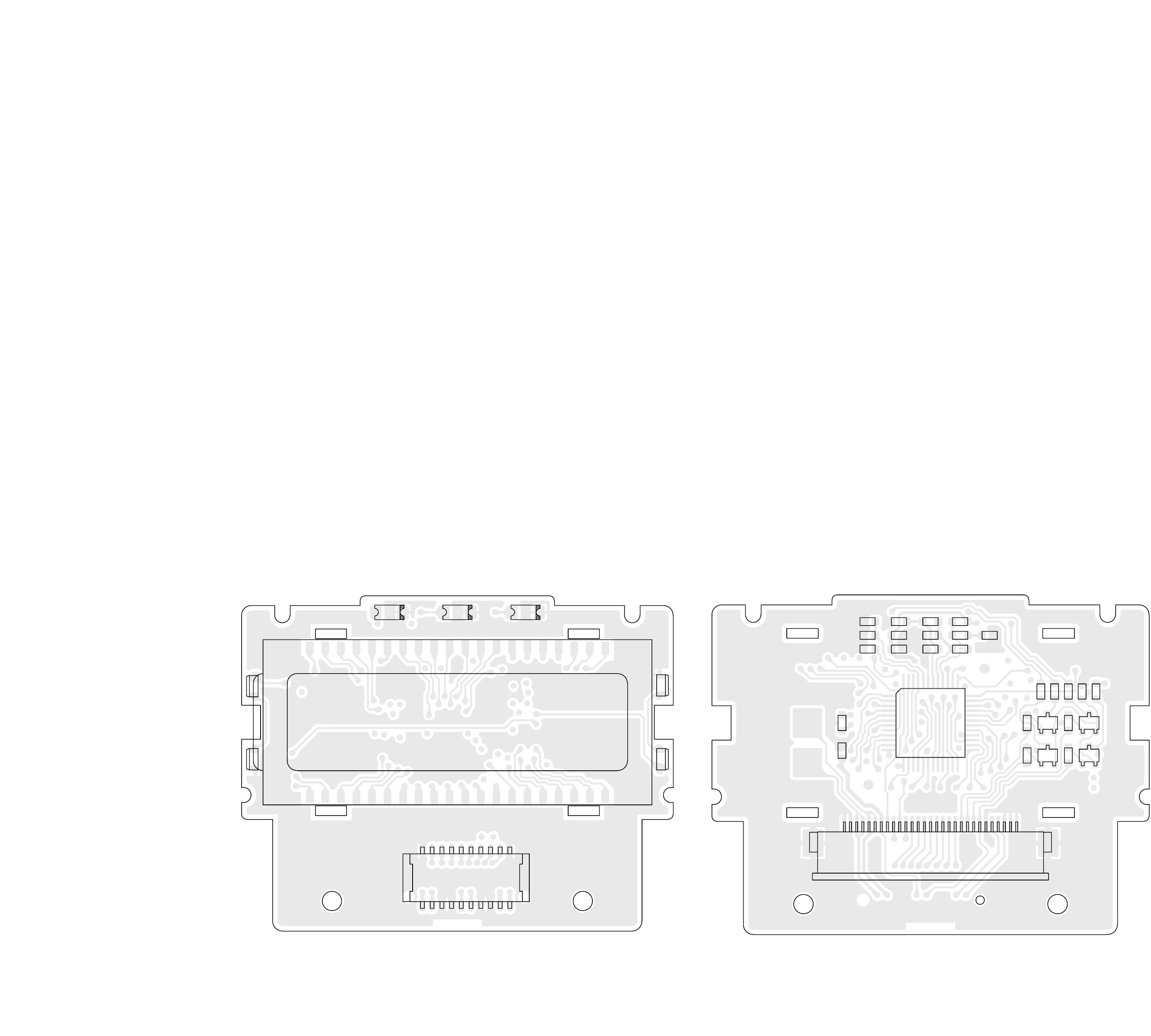
November 1999
Part No. 001-7780-500
R8
C2
R9 C4
C5
C7 HR2
C6
HR3
R3
R18
HR1
R7
Q2 Q4
Q1
Q3
1
29
J1
IC1
GND
GND
SPE
SPE
SP
SP
L5V
DISSO
DISSK
DISST
DISEN
KEYS0
KEYS1
KEYS2
KEYS3
KEYR0
KEYR1
KEYR2
KEYR3
TXLED
BSYLED
BATLED
BKLED
GND
MICE
MIC
GND
GND
GND
C1 R2
R13 R11
R14
R12
R16
R15
R1
C3
R17
DS3 DS4 DS5
DS1
DS2
J2
1
2
19
20
DS6
Tx LED Busy LED Batt LED
GND
KEYR3
KEYR2
KEYR1
KEYR0
KEYS3
KEYS2
KEYS1
KEYS0
GND
MIC
MICE
GND
GND
BKLED
L5V
GND
GND
SP
SPE
DS7
DS8
DISPLAY BOARD TOP VIEWDISPLAY BOARD BOTTOM VIEW
8-8
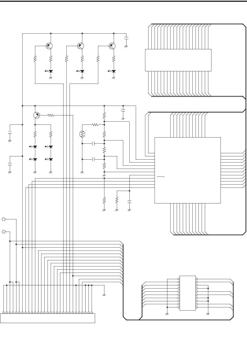
SCHEMATIC DIAGRAMS AND COMPONENT LAYOUTS
8-9 November 1999
Part No. 001-7780-500
K
C
S
M
O
S
M
P
S
E
P
S
D
N
G
D
N
G
E
P
SP
S
L
5
+
52204-2990
J1
9
28
27
26
25
24
23
22
21
20
29
18
17
16
15
14
13
12
11
10
1987654321
D
E
L
K
B
D
E
L
T
A
B
D
E
L
Y
S
B
D
E
L
X
T
3
R
Y
E
K
2
R
Y
E
K
1
R
Y
E
K
0
R
Y
E
K
3
S
Y
E
K
2
S
Y
E
K
1
S
Y
E
K
0
S
Y
E
K
N
E
S
I
D
T
S
S
I
D
C
I
M
E
C
I
M
D
N
G
D
N
G
D
N
G
D
N
G
KEYR3
KEYR2
KEYR1
KEYR0
KEYS3
KEYS2
KEYS1
KEYS0
GND
GND
AXN820735
J2
20 19
18 17
16 15
14 13
12 11
10 9
8 7
6 5
4 3
2 1
BKLED
SPE
SP
GND
GND
+5L
GND
GND
MICE
MIC
8
S
2
1
S
1
1
S
0
1
S
9
S
7
S
6
S
5
S
4
S
3
S
2
S
1
S
680P
C2
47K
R8
100K
R9
SPE
CP2
SP
CP1
33P
C1
0.047
C3
LNJ310M6URA
DS2
LNJ310M6URA
DS1
150
R2
150
R17
LNJ310M6URA
DS8
LNJ310M6URA
DS7
R
HR3
R
HR2
R
HR1
47K
R7
0.1
C6
0.1
C7
LC75834W
IC1
47 CL
46 CE
45 INH
44 OSC
43 VSS
42 VLCD2
41 VLCD1
40 VLCD
39 VDD
38 COM4
5
3
1
M
O
C
4
3
4
3
S
3
3
3
3
S
2
3
2
3
S
1
3
1
3
S
0
3
0
3
S
9
2
9
2
S
8
2
8
2
S
7
2
7
2
S
6
2
6
2
S
23
S23 22
S22 21
S21 20
S20 19
S19 18
S18 17
S17 16
S16 15
S15 14
S14
1
1
1
1
S
0
1
0
1
S
9
9
S
8
8
S
/
8
P
7
7
S
/
7
P
6
6
S
/
6
P
5
5
S
/
5
P
4
4
S
/
4
P
3
3
S
/
3
P
2
2
S
/
2
P
48 DI
37 COM3
6
3
2
M
O
C
5
2
5
2
S
24
S24
13
S13
2
1
2
1
S
1
1
S
/
1
P
S21
S20
S22
S23
S24
S13
S14
S15
S16
S17
S18
S19
2
S
4
1
S
3
1
S
0
1
S1
S6
S5
S
2
C1
C
1
3
S
9
S
7
1
S
8
1
S
2
2
S
5
2
S
6
2
S
9
2
S
4
3
S
2
3
S
3
3
S
4
3
S
5
2
S
6
2
S
7
2
S
8
2
S
9
2
S
0
3
S
0.1
C4
3
C1
C
4
C
4
C3
C
0
3
S
3
3
S
12K
R18
3.3K
R3
SEC1801C
DS5
SEC1401C
DS4
10K
R1
2SA1576 S
Q1
SEC1601C
DS3
TX LED
1K
R12
2SA1576
Q2
47K
R11
47K
R13
BUSY LED
1K
R14
47K
R15
820
R16
2SA1576
Q3
2SA1576
Q4
BATTERY
LD-BU10394J
DS6
0
4
2
S
9
3
5
S
8
3
6
S
7
3
1
S
6
3
9
S
5
3
0
1
S
4
3
3
1
S
3
3
4
1
S
2
3
7
1
S
1
3
8
1
S
0
3
2
2
S
9
2
5
2
S
8
2
6
2
S
7
2
9
2
S
6
2
4
3
S
5
2
0
3
S
4
2
3
3
S
3
2
1
C
2
2
3
C
1
2
4
C
0
2
2
C
9
1
1
C
8
1
3
C
7
1
2
3
S
6
1
1
3
S
5
1
8
2
S
4
1
7
2
S
3
1
4
2
S
2
1
3
2
S
1
1
1
2
S
0
1
0
2
S
9
9
1
S
8
6
1
S
7
5
1
S
6
2
1
S
5
1
1
S
4
8
S
3
7
S
2
4
S
1
3
S
33P
C5 1
3
S
2
3
S
1
C
2
C3
C4
S
7
S
6
1
S
5
1
S
2
1
S8
S
7
2
S
1
1
S
8
2
S
9
1
S
4
2
S
3
2
S
1
2
S
0
2
S3
S
DISPLAY BOARD SCHEMATIC
SCHEMATIC DIAGRAMS AND COMPONENT LAYOUTS
8-10
November 1999
Part No. 001-7780-500
DS1
DS3
DS4
DS2
1
(PHON) 2
(STR) 3
(HOME) SYS
(RCL)
GRP
(CLR)
6
5
4
7
(S.A/D) 89
SCAN
(SND)
#
0
( )
*
J1
HC5
HC6
HC7
HC8
1
2
20
19 Q1
HC11
HC12
HC10
HC9
SPE
SP
GND
GND
L5V
BKLED
GND
GND
MICE
MIC
HC2 R3 R5 HC4
HC3
R4
R12
R11
R10 R2 HC1
C5
GND
KEYS0
KEYS1
KEYS2
KEYS3
KEYR0
KEYR1
KEYR2
KEYR3
GND
C3
C4
C2
R1
C1
SPEAKER
MICROPHONE
10-KEY BOARD FRONT VIEW
10-KEY BOARD BACK VIEW
SCHEMATIC DIAGRAMS AND COMPONENT LAYOUTS
8-11 November 1999
Part No. 001-7780-500
D
E
L
K
B
E
P
SP
S
D
N
G
D
N
G
L
5
+
D
N
G
D
N
G
E
C
I
M
AXN720535
J1
0
2
9
1
8
1
7
1
6
1
5
1
4
1
3
1
2
1
1
1
0
1
9
8
7
6
5
4
3
2
1
C
HC10
C
HC9
C
I
MC
HC12
C
HC11
120
R10
LN1371G-(TR)
DS1
LN1371G-(TR)
DS2
LN1371G-(TR)
DS3
LN1371G-(TR)
DS4
120
R11
33P
C5
S15
C
HC4
C
HC3
#S12
9S9
10K
R12
C
HC2
0S11
8S8
2SA1576
Q1
C
HC8
C
HC1
*
S10
7S7
C
HC6
C
HC7
D
N
G
3
R
Y
E
K
2
R
Y
E
K
1
R
Y
E
K
0
R
Y
E
K
3
S
Y
E
K
2
S
Y
E
K
1
S
Y
E
K
0
S
Y
E
K
D
N
G
C
HC5
4S4
1S1
5S5
2S2
6S6
3S3
S14
S13
100K
R5
100K
R4
33P
C4
100K
R3
100K
R2
33P
C3
33P
C2
33P
C1
33K
R1
SP1
MC1
Microphone
Speaker
F1
F2
F3
10-KEY BOARD SCHEMATIC
SCHEMATIC DIAGRAMS AND COMPONENT LAYOUTS
8-12
November 1999
Part No. 001-7780-500
SPEAKER
MICROPHONE
C4
C2
C1
R1
Q1
J1
HC8
HC7
C3
HC6
R8
R6
HC5
R4
R3
R2
HC1
C5
HC4
HC3
HC2
1
19
20 2
DS1
DS2
SCAN A/D
( ) MENU
3-KEY BOARD FRONT VIEW
3-KEY BOARD BACK VIEW
SCHEMATIC DIAGRAMS AND COMPONENT LAYOUTS
8-13 November 1999
Part No. 001-7780-500
D
E
L
K
B
D
N
G
E
P
SP
S
D
N
G
L
5
+
D
N
G
D
N
G
E
C
I
M
AXN720535
J1
0
2
9
1
8
1
7
1
6
1
5
1
4
1
3
1
2
1
1
1
0
1
9
8
7
6
5
4
3
2
1
C
I
M
LN1371G-(TR)
DS1
LN1371G-(TR)
DS2
220
R6 33P
C5
10K
R8
2SA1576
Q1
C
HC8
C
HC7
C
HC6
C
HC5
D
N
G
2
S
Y
E
K
3
R
Y
E
K
2
R
Y
E
K
1
R
Y
E
K
0
R
Y
E
K
3
S
Y
E
K
1
S
Y
E
K
0
S
Y
E
K
D
N
G
C
HC1
S1
C
HC2
C
HC3
S2 S3
C
HC4
100K
R4
33P
C4
100K
R3
100K
R2
33P
C3
33P
C2
33P
C1
33K
R1
SP1
MC1
F1 F2 F3
Microphone
Speaker
3-KEY BOARD SCHEMATIC

SCHEMATIC DIAGRAMS AND COMPONENT LAYOUTS
8-14
November 1999
Part No. 001-7780-500
NOTES

Part No. 001-7780-500
11-99hph Printed in U.S.A.
