Ehong Technology MB05 Bluetooth Module User Manual
ShangHai Ehong Technology Co.,Ltd. Bluetooth Module Users Manual
UserManual.wiki
>
Ehong Technology
>
MB05 User Manual
>
Users Manual
Contents
1.
Users Manual
2.
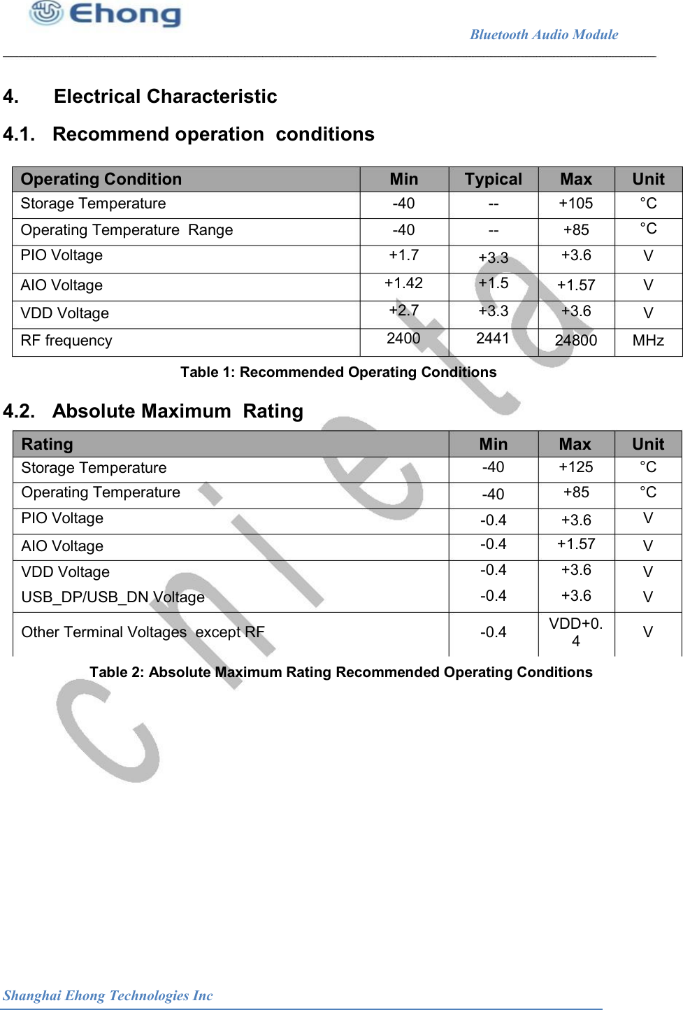
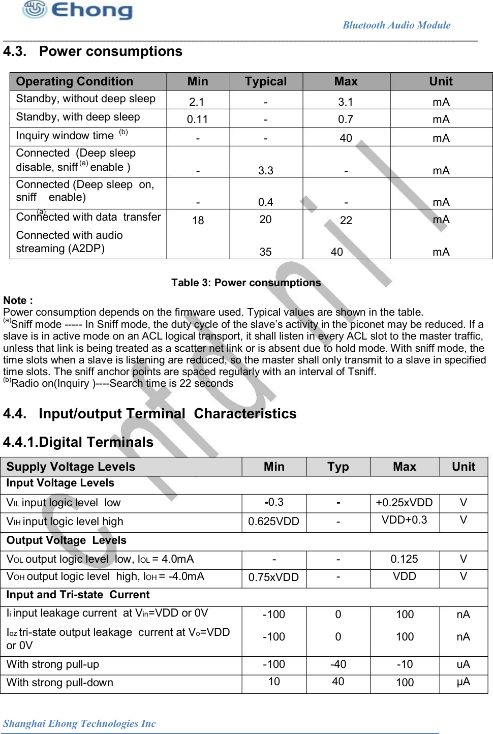
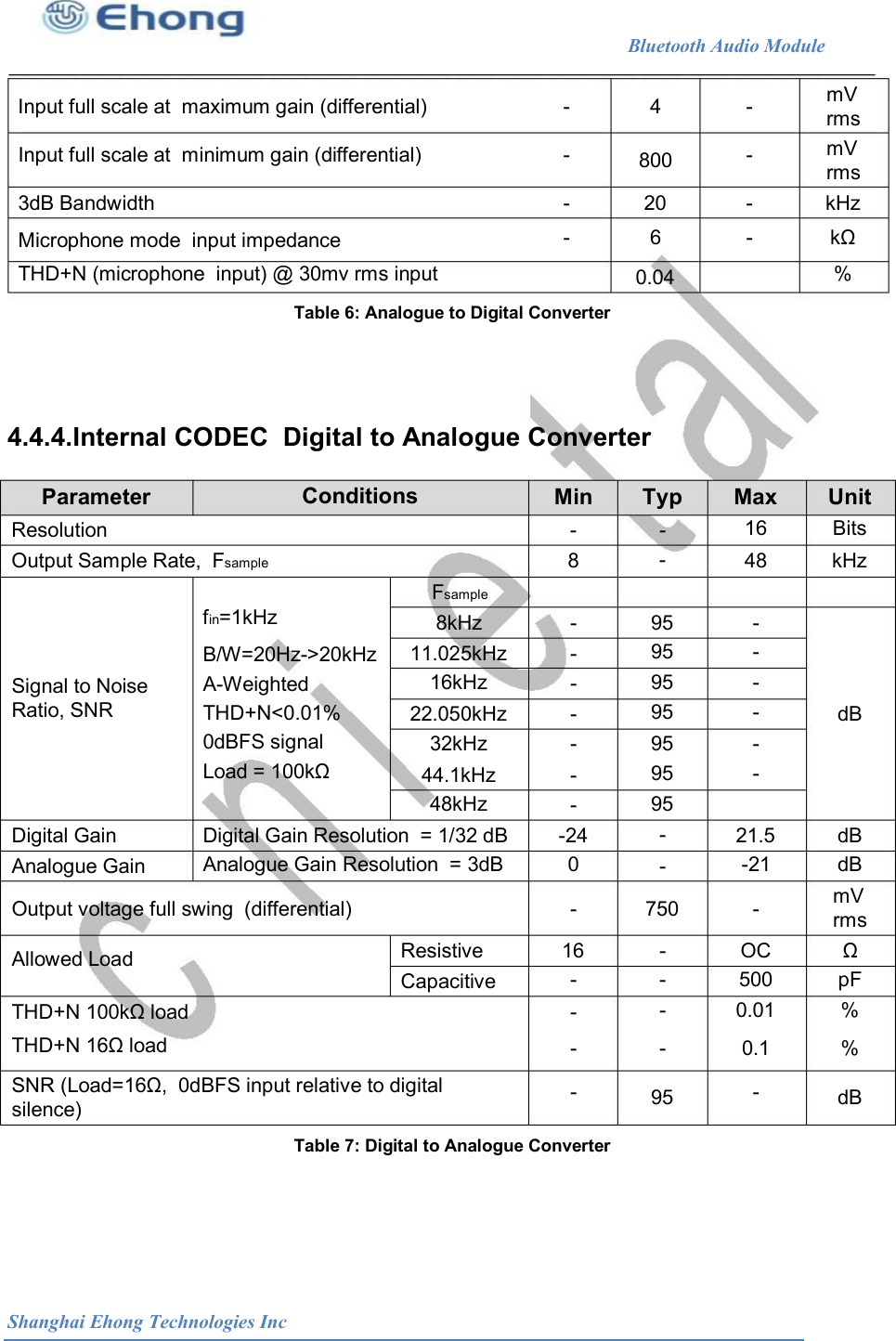
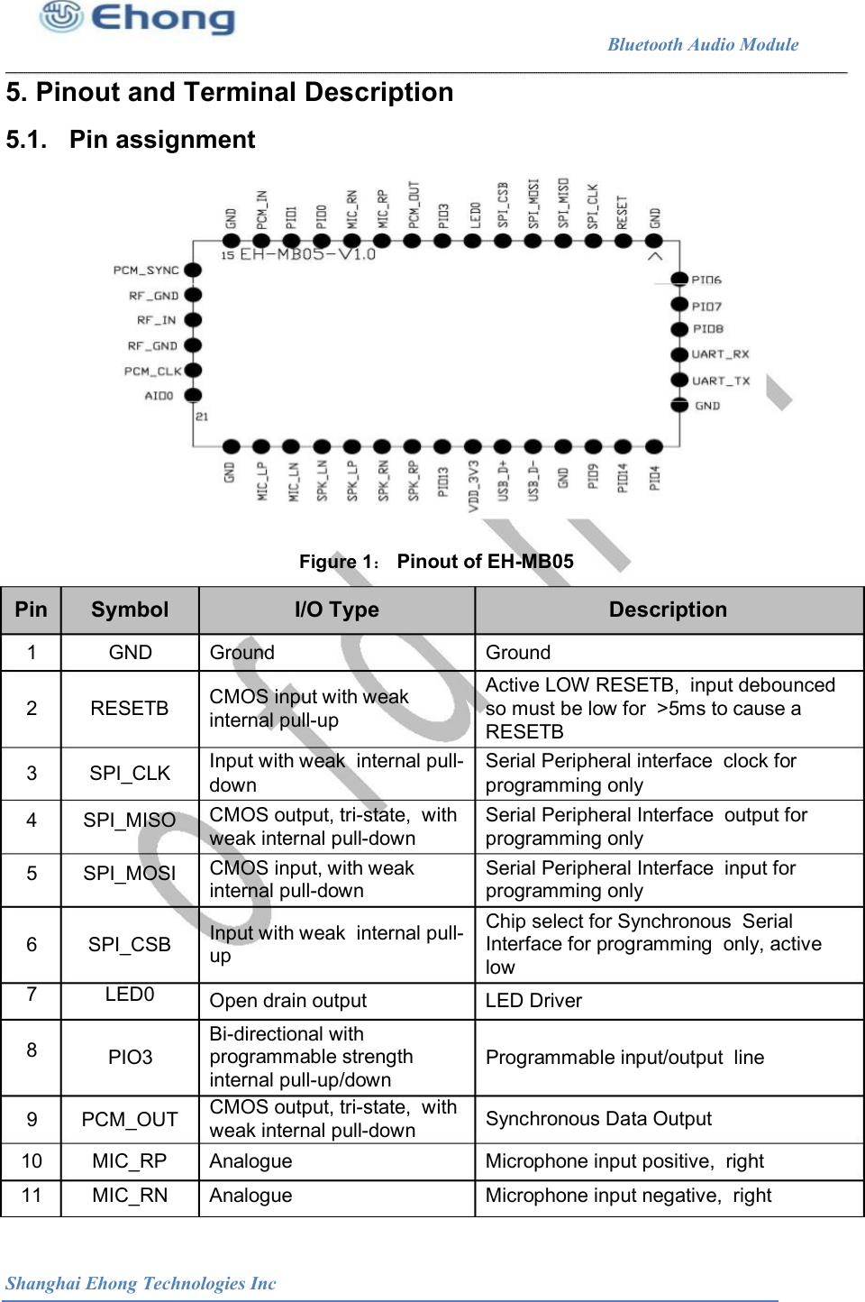
User Manual
Users Manual
Navigation menu
Upload a User Manual
Namespaces
Wiki Guide
HTML
PDF
Info
Views
User Manual
Discussion / Help
Navigation
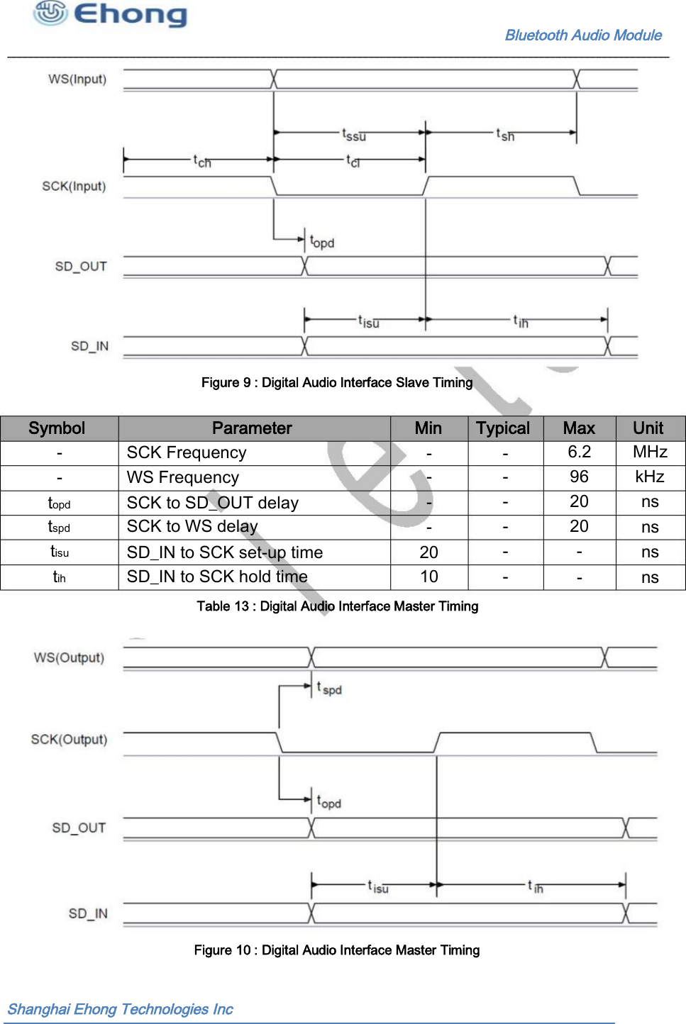
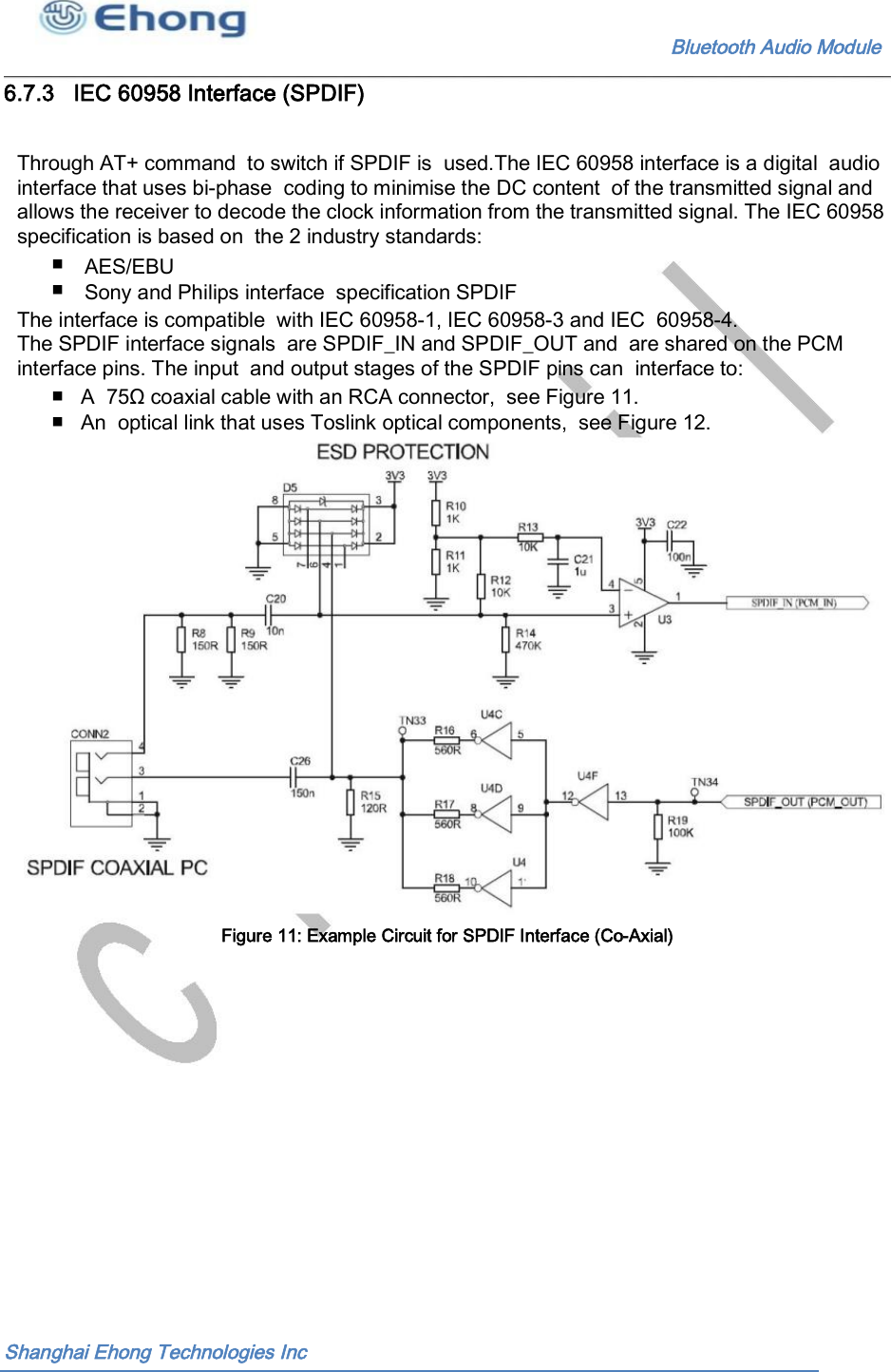
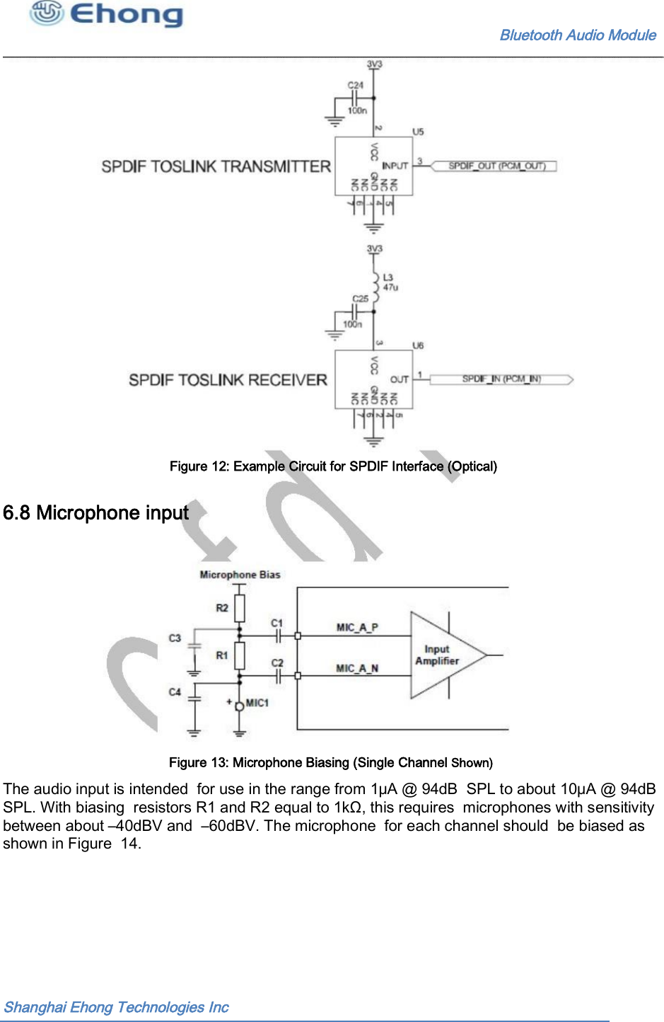
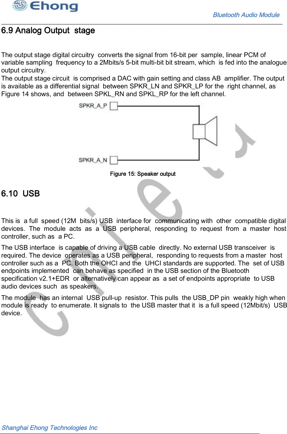

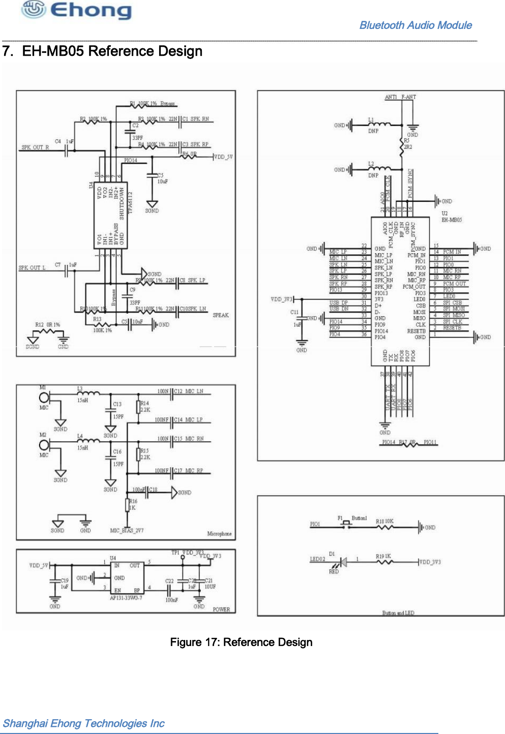
![Bluetooth Audio Module —Reorient or relocate the receiving antenna. —Increase the separation between the equipment and receiver. —Connect the equipment into an outlet on a circuit different from that to which the receiver is connected. —Consult the dealer or an experienced radio/TV technician for help. In accordance with FCC Part 15C, this module is listed as a Limited Modular Transmitter device. Therefore, the final host product must be submitted to [ShangHai Ehong Technology Co.,Ltd.] for confirmation that the installation of the module into the host is in compliance with the regulations of FCC and IC Canada. Specifically, if an antenna other than the model documented in the Filing is used, a Class 2 Permissive Change must be filed with the FCC. Changes or modifications not expressly approved by the manufacturer could void the user’s authority to operate the equipment. Ehong Technology Co., Ltd](https://usermanual.wiki/Ehong-Technology/MB05.Users-Manual/User-Guide-3345802-Page-30.png)