El Paso Chile Company Dms 3040 40 Users Manual OM163 DMS3040 80 120
OM163 to the manual e53e7a29-a7ac-4bcd-a3e6-b3ce30c501cc
2015-02-02
: El-Paso-Chile-Company El-Paso-Chile-Company-Dms-3040-40-Users-Manual-426518 el-paso-chile-company-dms-3040-40-users-manual-426518 el-paso-chile-company pdf
Open the PDF directly: View PDF ![]() .
.
Page Count: 32
© copyright Paso Sound Products, Inc. 2003 Specifications are subject to change without notice
Innovation through technology since 1931
LISTED
COMMERCIAL
AUDIO
EQUIPMENT
30TJ
Installation Manual
and Operating Instructions
7 Channel - 3 Zone - Dual VOX -
Dual Mute - MOH - Vox Relay -
Module Port - Phone Interface
TTOO RREEDDUUCCEE TTHHEE RRIISSKK OOFF FFIIRREE OORR EELLEECCTTRRIICC
SSHHOOCCKK DDOO NNOOTT EEXXPPOOSSEE TTHHIISS AAPPPPLLIIAANNCCEE TTOO
WWAATTEERR,, RRAAIINN OORR MMOOIISSTTUURREE
CAUTION !
REV. 1.5
IMPORTANT NOTE:
THIS OPERATING MANUAL IS PROVIDED AS AN INSTALLATION AND
AS AN OPERATING AID. PASO SOUND PRODUCTS, INC. DOES NOT ASSUME ANY
RESPONSIBILITY AS TO ITS ACCURACY AND SHALL NOT BE LIABLE IN TORT OR CON-
TRACT FOR ANY DIRECT CONSEQUENTIAL OR INCIDENTAL LOSS OR DAMAGE ARISING
FROM THE INSTALLATION, USE OR INABILITY TO USE THIS PRODUCT.
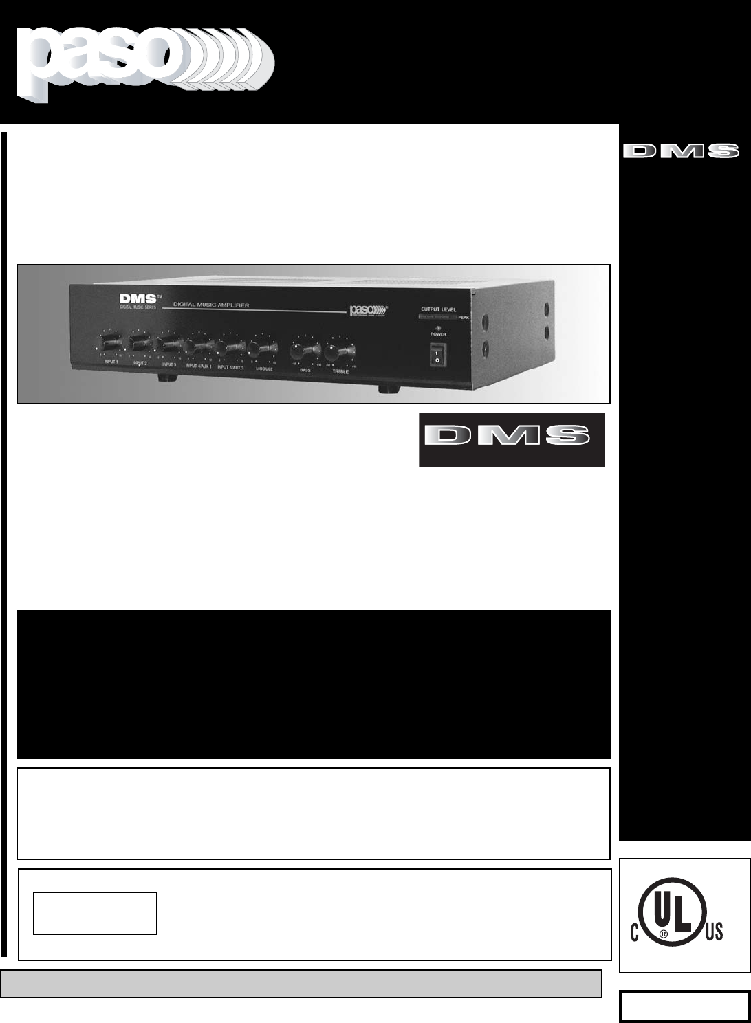
DDMMSS 33004400 -- 4400 WWaatttt RRMMSS
DDMMSS 33008800 -- 8800 WWaatttt RRMMSS
DDMMSS 33112200 -- 112200 WWaatttt RRMMSS
TM
DIGITAL MUSIC SERIES
PROFESSIONAL AUDIO & SOUND
®
Series DMS
Integrated Amplifiers
Manual
OOMM116633
DDiiggiittaall MMuussiicc AAmmpplliiffiieerrss
TM
DIGITAL MUSIC SERIES

DESCRIPTION AND APPLICATIONS SPECIFICATIONS
PAGE 2 © copyright Paso Sound Products, Inc. 2002 Specifications are subject to change without notice DMS3040/3080/3120
Power Output:
DMS3040
DMS3080
DMS3120
Distortion:
Frequency Response:
Inputs: Input 1
Input 2
Input 3
Input 4
Input 5
Input 6
Input 7
Sensitivity & Z:
Input 1
Input 2
Input 3
Input 4
Input 5
Input 6
Input 7
AUX 1 Input
Attenuator:AUX 2 Input
Attenuator:
Phantom Power:
Hum & Noise:
Telephone Paging Input:
Accessory Port:
EQ LINK:
Line Outputs:
Inputs/Outputs:
Subwoofer Outputs:
Subwoofer Output Level:
Music on Hold Output:
Zone 2 Output:
Zone 3 Output:
Main Output Impedance:
Controls: Front Panel:
Rear Panel:
Bass and Treble Controls:
Tone By-Pass:
Remote Volume Controls:
MOH Source Selection:
Zone 2/3 Source Selection:
DUAL VOX:
VOX BUSS 1:
VOX BUSS 2:
MUTE BUSS 1:
MUTE BUSS 2:
MUTE 2 DELAY:
Unmuting:
Power Supply Output:
Auto VOX Relay:
Rack Mounting:
Internal Cooling Fan:
Power Requirement:
Power Consumption:
AC Accessory Outlet:
Terminations:
Housing Finish:
Output Power Indicator:
Dimensions:
Net Weight:
DMS3040
DMS3080
DMS3120
UNPACKING
Immediately upon receipt of the amplifier, inspect the unit
and shipping container for indications of improper handling
or in transit damage. The equipment was carefully inspect-
ed and tested before leaving the factory. Notify the
Transportation Company immediately if any damage is
found. ONLY THE CONSIGNEE CAN FILE A CLAIM WITH
THE CARRIER FOR DAMAGE DURING SHIPMENT. Be
sure to save the carton and packing material as evidence of
damage for the shipper inspection. DO NOT SHIP the unit
back to the factory unless authorized by the factory.
IN TRANSIT DAMAGES ARE NOT COVERED BY THE
PASO WARRANTY.
40 Watt RMS
80 Watt RMS
120 Watt RMS
Less than 0.5% THD
20 - 20,000 Hz ± 1 db
Microphone 1 Balanced
Microphone 2 Balanced
Microphone 3 Balanced
Microphone 4 Balanced - AUX 1
(Stereo Summing)
Microphone 5 Balanced - AUX 2
(Stereo Summing)
Telephone Interface - Transformer Balanced
Module Port
Mic 1
= 1.5 Mv - 250 ohm
Mic
2 = 1.5 Mv - 250 ohm
Mic 3
= 1.5 Mv - 250 ohm
Mic 4
= 1.5 Mv - 250 ohm - AUX 1 = 100 Mv - 47K
ohm
Mic 5
= 1.5 Mv - 250 ohm - AUX 2 = 100 Mv - 47K
ohm
Tel
=100 Mv - 600 ohm - Transformer Balanced
Module
= 1 V - 47K ohm
Variable (rear panel control)
Variable (rear panel control)
All Microphone Inputs by internal jumper (18 V)
Mic
-70 db,
Aux
-75 db
600 ohm Transformer balanced
Accepts Standard Module
Preamp out, Power Amp in with EQ Link Switch
Line Out 600 ohm - 1.5 V loaded
MIX BUSS
Pre-EQ and Post-EQ Outputs
1 Volt
600 ohm-1 Volt Transformer Balanced
1 Watt-8 ohm with Control
1 Watt-8 ohm with Control
8 ohm, 25 Volt and 70 Volt line
Input 1 Level, Input 2 Level, Input 3 Level, Input 4
Level, Input 5 Level, Module Level, Bass and Treble
PHONE Level - AUX 1 Attenuator - AUX 2 Attenuator
- MOH/ZONE 1 Level Control - ZONE 2 Level Control
- VOX 1/VOX 2 Sensitivity - MUTE 2 Delay
± 10 dB at 100 Hz and 10 KHz
On - Off Switch
(rear panel)
AUX 1 Input Level and Master Volume (10 K)
AUX 1 - AUX 2 - MODULE by internal jumper
AUX 1 - AUX 2 - MODULE by internal jumper
Voice Activated Muting
Available on all 7 Inputs by internal jumpers
Available on all 7 Inputs by internal jumpers
Available on all 7 Inputs by internal jumpers
Available on all 7 Inputs by internal jumpers
Adjustable from 3 Sec to 30 Sec (rear panel control)
MUTES/UNMUTES MIC 1 only
24 V DC - 250 mA Regulated
NO/NC Contacts - VOX activated - Contacts Rating =
30 VDC - 7 A
Optional Model 27/3501 - 19” Rack Kit
3” Thermally Controlled -
Model DMS3120 only
117 Volt, 50-60 Hz
DMS3040 = AC = 630 VA - DMS3080 = 750 VA -
DMS3120 = 850VA Max.
500 W Max. Unswitched
Screw Terminals, RCA Jacks
Black
Multi-color LED
(front panel)
19” W., 12” D., 4” H. with feet
(482X305X102 mm)
3.5”
H
(89 mm)
. less feet
16 Lbs
(8 Kg)
19 Lbs
(8.5 Kg)
22 Lbs
(11 Kg)
❑❑High Performance - High Reliability Design
❑❑Wide Frequency Response - Very Low Distortion
❑❑7 Channel Inputs - 3 Zone Outputs
❑❑5 Balanced Microphone Inputs
❑❑Phantom Power on all MIC Inputs
❑❑MIC 4/AUX 1 and MIC 5/AUX 2 Inputs
With Stereo Summing
❑❑AUX1 and AUX2 Inputs Attenuator
❑❑600 ohm Transformer Balanced
Telephone Paging Input
❑❑MIX Buss and 600 ohm Line Output
❑❑Independent Input Controls
❑❑Rear Panel Port: Accepts Standard Module
❑❑Independent Module Level Control
❑❑AUX1 and Master Remote Volume Controls
❑❑External EQ Link
❑❑Tone by-pass and EQ Link switches
❑❑Pre-EQ Subwoofer Output
❑❑Post-EQ Subwoofer Output
❑❑Addressable Dual VOX Buss
Voice Activated Muting
❑❑VOX Variable Time Delay Function
❑❑Addressable Dual MUTE Buss
❑❑Direct Muting and Unmuting
❑❑600 ohm and 8 ohm 1 Watt
Music on Hold Amplifier
❑❑MOH Amplifier Source Selector
❑❑Zone 2 and 3, 1 Watt - 8 ohm Output
with Separate Control
❑❑NO/NC VOX Operated Relay
❑❑24 V DC 250 mA Regulated Power Supply Output
❑❑8 ohm, 25 Volt & 70 Volt Output
❑❑Optional 19” Rack Mounting with Kit
❑❑Low profile - 2-Unit of Vertical Rack space
❑❑UL 6500 Listed (US - CANADA)
PROFESSIONAL AUDIO & SOUND
®
TM
DIGITAL MUSIC SERIES
DIGITAL MUSIC AMPLIFIERS
PAGE 3
SPECIFICATIONS ARE SUBJECT TO CHANGE WITHOUT NOTICEDMS3040/3080/3120
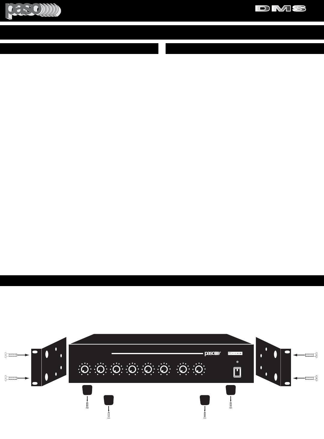
RACK MOUNTING
A) Procure the optional accessory Rack Mount Kit Model 27/3501.
B) Turn amplifier up side down and remove the four rubber feet by unscrewing the four holding screws.
C) Remove two screws on each side of the amplifier holding the amplifier cover.
D) Install the rack kit brackets by using the self-tapping screws provided.
DIGITAL MUSIC AMPLIFIER
O
POWER
PROFESSIONAL AUDIO & SOUND
DIGITAL MUSIC SERIES
DMS
DMS
TM
OUTPUT LEVEL
PEAK
INPUT 1 INPUT 2 INPUT 3 INPUT 4/AUX 1 INPUT 5/AUX 2 BASS TREBLEMODULE
100100100100100100+10-10 +10-10
Fig. 3 - Rack Kit Mounting
READ BEFORE OPERATING READ BEFORE OPERATING
BEFORE OPERATING THE AMPLIFIER, BE SURE YOU
FULLY UNDERSTAND ALL INSTRUCTIONS AND FEA-
TURES OF THE UNIT.
1) Read these instructions carefully.
2) Keep these instructions.
3) Heed all Warnings.
4) Follow all instructions.
5) DO NOT use this apparatus near water.
6) Clean ONLY with a damp cloth.
7) DO NOT block any of the ventilation openings.
Install in accordance with the instructions provided.
8) DO NOT install near any heat sources such as
radiators, stoves, or other apparatus (including ampli-
fiers) that produce heat.
9) DO NOT mount amplifier into a container or a
closed unventilated closet while operating.
10) DO NOT place any object or accessory equipment
such as Tuners, Mixers, Cassette Decks, etc. on top of
the amplifier. Obstructing or closing the cabinet venti-
lation openings may cause overheating.
11) DO NOT defeat the safety purpose of the polar-
ized or grounding type plug. A polarized plug has two
blades with one wider than the other. A grounding type
plug has two blades and a third grounding prong. The
wide blade and or the third prong is provided for your
safety. When the provided plug does not fit into your
outlet, consult an electrician for replacement of the
obsolete outlet.
12) Use only the attachments and accessories speci-
fied in this manual.
13) If a cart is used, use caution when moving the
cart/apparatus combination to avoid injury from tip-
over.
14) Unplug this apparatus during lighting storms or
when unused for long periods of time.
15) Refer all servicing to qualified service personnel.
Servicing is required when the apparatus has been
damaged in any way, such as power supply cord or
plug is damaged, liquid has been spilled or objects
have fallen into the apparatus, the apparatus has been
exposed to rain or moisture, does not operate normal-
ly, or has been dropped.
16) DO NOT replace fuses unless power cord is
removed from the AC wall outlet.
17) DO NOT install accessories unless the power
cord is removed from the AC wall outlet.
TO REDUCE THE RISK OF FIRE OR
ELECTRIC SHOCK DO NOT EXPOSE
THIS APPLIANCE TO WATER, RAIN OR
MOISTURE
IMPORTANT SAFETY INSTRUCTIONS
PROFESSIONAL AUDIO & SOUND
®
TM
DIGITAL MUSIC SERIES
DIGITAL MUSIC AMPLIFIERS
PAGE 4 SPECIFICATIONS ARE SUBJECT TO CHANGE WITHOUT NOTICE DMS3040/3080/3120
DIGITAL MUSIC AMPLIFIER
O
POWER
PROFESSIONAL AUDIO & SOUND
DIGITAL MUSIC SERIES
DMS
DMS
TM
OUTPUT LEVEL
PEAK
INPUT 1 INPUT 2 INPUT 3 INPUT 4/AUX 1 INPUT 5/AUX 2 BASS TREBLEMODULE
100 100 100 100 100 100 +10-10 +10-10
12 3 4 5 6 7 8 9
10
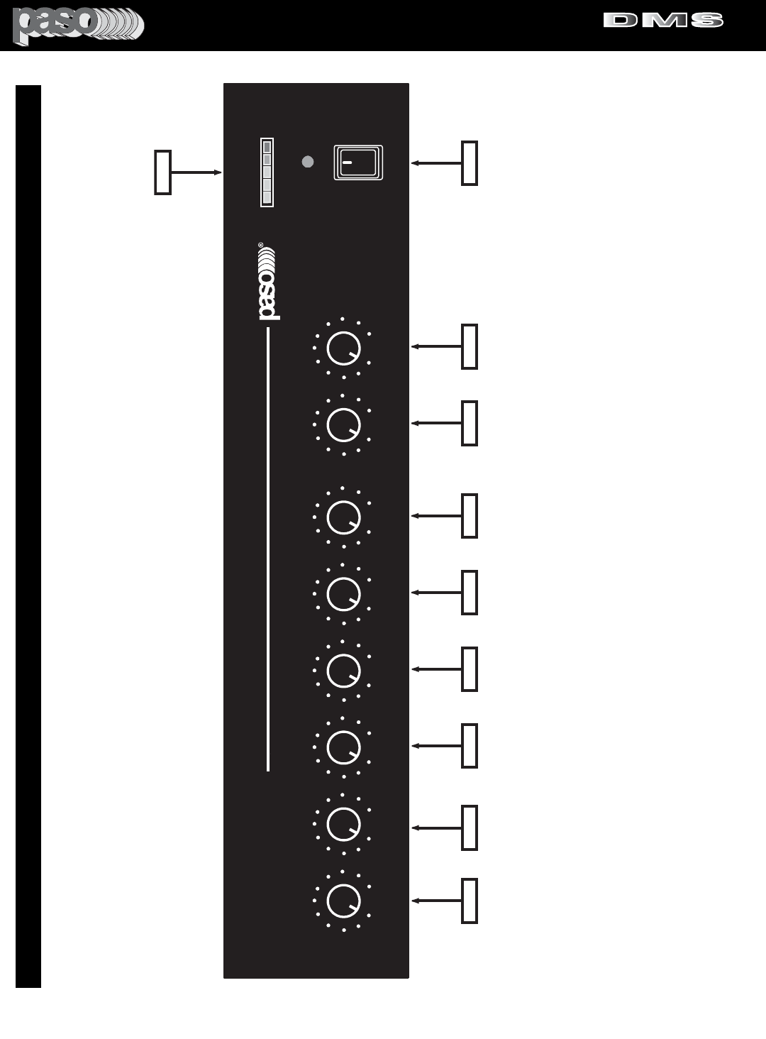
1) INPUT 1 Volume Control
2) INPUT 2 Volume Control
3) INPUT 3 Volume Control
4) INPUT 4/AUX 1 Volume Control
5) INPUT 5/AUX 2 Volume Control
6) Input Module Level Control
7) BASS Control
8) TREBLE Control
9) On-Off Power Switch
10) Output Level Meter
Fig. 4 - FRONT PANEL CONTROLS
PROFESSIONAL AUDIO & SOUND
®
TM
DIGITAL MUSIC SERIES
DIGITAL MUSIC AMPLIFIERS
PAGE 5
SPECIFICATIONS ARE SUBJECT TO CHANGE WITHOUT NOTICEDMS3040/3080/3120
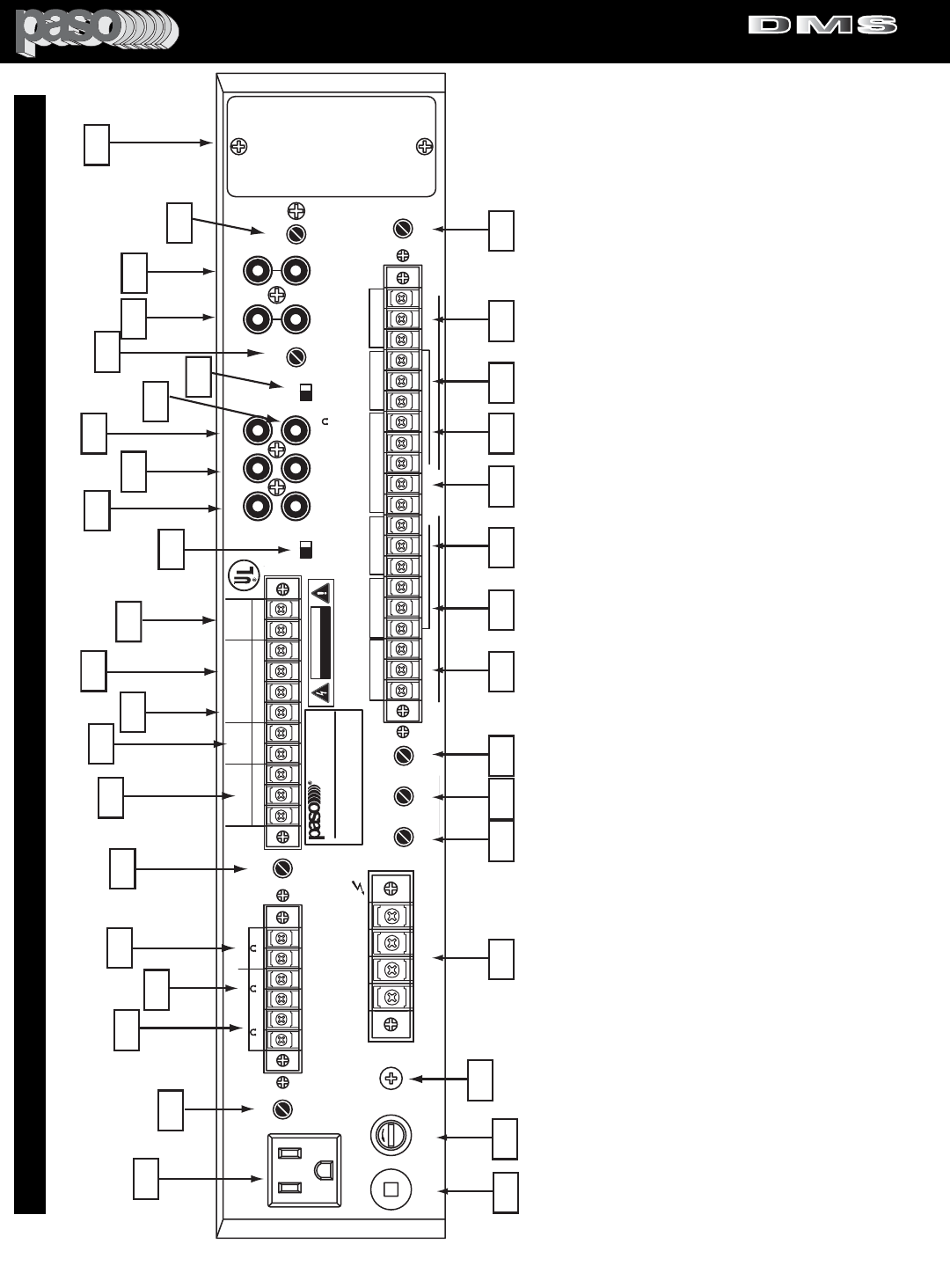
DMS3120 Rear Panel
Manual
23
35
1
2
3
4
58
7
9
17
12
11
10
16
22
20
18
6
15
13
14 19
21
2425262728293031323334
36
37
SER. NO.
ATTENTION:
AFIN DE REDUIRE LE RISQUE
D'INCENDIE REMPLACER SEUL PAR UN
FUSIBLE DE MEME TYPE.
CLASS 2 WIRING ACCEPTABLE
COM 8 25V 70V
SPEAKER OUTPUT
GROUND
LINE FUSE
5A 250V
117V 500W MAX
117V 60HZ
R
L
LEVEL LEVEL
EQ LINK
ATTENUATOR ATTENUATOR
VOX-1
UNSWITCHED
0 600
ZONE 2
ZONE 1 24V DC
250 mA
0 8 0 8
VOX-2 MUTE-2
SENS
SENS DELAY
IN OUT
TEL
G COM HOT
NC C NO
+-
MIC1 G M2 M1 RVC
VOX RELAY
GROUND
UNMUTE
MUTE 1
MUTE 2
47kohm 100mV
(AUX1) (AUX2)
LEVEL
TEL OUTPUT
ZONE 2
ZONE 1
INPUT-4(AUX1)
BALANCED
INPUT 5
MIC-AUX2
BY INTERNAL
SWITCH
250ohm 1.5mV
47kohm 100mV
INPUT-5(AUX2)
ON OFF
POWER RATING
SUPPLY VOLTAGE
POWER CONSUMPTION
120 W RMS
117V 60 HZ
850 VA
DMS3120
LISTED
COMMERCIAL
AUDIO
EQUIPMENT
30TJ
CUS
MIX
BUSS
LINE OUT
600
PRE
OUT
POWER
IN
SUB OUT
PRE EQ
SUB OUT
POST EQ TONE
BYPASS
CAUTION: TO REDUCE THE RISK OF FIRE OR
SHOCK DO NOT EXPOSE THIS APPLIANCE TO
RAIN OR MOISTURE. DO NOT REMOVE COVER.
THERE ARE NO USER SERVICEABLE PARTS
INSIDE. REFER SERVICING TO QUALIFIED
SERVICE PERSONNEL.
DIGITAL MUSIC AMPLIFIER
CAUTION: TO REDUCE THE
RISK OF FIRE, REPLACE
ONLY WITH SAME TYPE
FUSE.
MOH OUT
BALANCED
MASTER
REMOTE
VOLUME
EQ LINK
PORT ACCEPTS
STANDARD
MODULE
CAUTION: REMOVE
POWER CORD FROM
AC OUTLET PRIOR TO
INSTALLING MODULE
CAUTION
RISK OF ELECTRIC SHOCK
DO NOT OPEN
WARNING: THIS APPLIANCE
MUST BE EARTHED
ATTENTION: POUR REDUIRLES RISQUES D' INCENDIE
OU DE CHOC ELECTRIQUE, NE PAS EXPOSER A LA PLUIE
OU L' HUMIDITE, NE PAS ENLEVER LE COUVERCLE. AUCUN
REGLAGE A L' INTERIEUR. POUR REPARATION CONSULTER
UNE PERSONNE QUALIFIEE
INPUT 4 (MIC) INPUT 3 (MIC)
INPUT 2 (MIC)
INPUT 1 (MIC)
G COM HOT RVC RVC G COM HOT G COM HOT G COM HOT G COM HOT
INPUT 4
REMOTE
VOLUME
RVC
PROFESSIONAL AUDIO & SOUND
1 WATT 1 WATT
AUX2
47Kohm 100 mV
INPUT5 (MIC-AUX2)
600 ohm 100mV
Fig. 5- REAR PANEL INPUTS - OUTPUTS - CONTROLS
1) Unswitched AC Auxiliary Socket
2) ZONE 1 - Output Level Control
3) Zone 1 MOH - 600 ohm, 1 Volt Output
4) Zone 1 - 8 ohm, 1 Watt Output
5) Zone 2 - 8 ohm, 1 Watt Output
6) ZONE 2 - Output Level Control
7) VOX Relay NO/NC Contact Terminals
8) 24 Volt DC Regulated Power Supply Output
9) MIC 1 UNMUTE
10) MUTE 1 - MUTE 2 Terminals
11) Master Remote Volume Control Terminals
12) EQ LINK - IN - OUT Switch
13) EQ LINK - PREAMP. OUT/POWER AMP IN
14) SUB OUT - PRE EQ and POST EQ
15) MIX BUSS
16) LINE OUT 600 Ohm
17) TONE BYPASS - ON/OFF SWITCH
18) AUX 1 Input Attenuator
19) INPUT 4/AUX 1 - Stereo Summing Jacks
20) INPUT 5/AUX 2 - Stereo Summing Jacks
21) AUX 2 Input Attenuator
22) Standard Module Port
23) TELEPHONE Paging Output Level Control
24) TELEPHONE Paging Balanced Input 600 Ohm
25) INPUT 5/AUX 2 - Balanced Input
26) INPUT 4/AUX 1 - Remote Volume Control Terminals
27) INPUT 4 - Balanced MIC Input
28) INPUT 3 - Balanced MIC Input
29) INPUT 2 - Balanced MIC Input
30) INPUT 1 - Balanced MIC Input
31) MUTE 2 Time Delay Control
32) VOX 2 Sensitivity Control
33) VOX 1 Sensitivity Control
34) Speaker Output Terminals
35) Chassis Ground
36) AC LIne Fuse
37) AC Power Cord
PROFESSIONAL AUDIO & SOUND
®
TM
DIGITAL MUSIC SERIES
DIGITAL MUSIC AMPLIFIERS
PAGE 6 SPECIFICATIONS ARE SUBJECT TO CHANGE WITHOUT NOTICE DMS3040/3080/3120
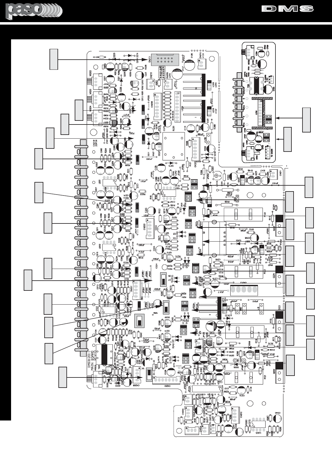
Fig. 6 - MAIN PCB AND MOH BOARD TOP VIEW
FUNCTION SWITCHES AND JUMPERS LOCATION
SW215
INPUT1
V2 V1 OFF
SW220
INPUT1
M2 M1 OFF
SW201 (MIC1)
ON OFF
V2 V1 OFF
SW210
INPUT2
SW219
INPUT2
M2 M1 OFF
V2 V1 OFF
SW211
INPUT3
SW218
INPUT3
M2 M1 OFF
T204
IT - 5000
SW203 (MIC3)
ON OFF
SW202 (MIC2)
ON OFF
SW204 (MIC4)
ON OFF
SW207
(MIC5)
ON OFF
(INPUT4/AUX1)
V2 V1 OFF
SW212
SW217
(INPUT4/AUX1)
M2 M1 OFF
V2 V1 OFF
SW213
(INPUT5/AUX2)
SW223
INPUT5/AUX2
M2 M1 OFF
SW214
(TEL)
V2 V1 OFF
SW216
(TEL)
M2 M1 OFF
SW221
SW222
V2 V1 OFF
(MODULE)
M2 M1 OFF
(MODULE)
SW206
(VOX RELAY)
M2 M1
SW205
(UNMUTE)
ON OFF
(CHIME TRIGER)
M2 M1
SW227
SW208
(INPUT5)
AUX2 MIC
SW229
AUX2 MIC5
(INPUT5)
SW228
(INPUT4)
AUX1 MIC4
SW209
(MODULE IN)
AUX2 AUX1
AMPLIFIER REAR PANEL
INPUT 1
(MIC)
INPUT 2
(MIC)
INPUT 3
(MIC)
INPUT 4
(MIC)
HOTRVC RVC COM GNDHOT COM GNDHOT COM GND HOT COM GND HOT COM GND HOT COM GND
AUX 2
INPUT 5
INPUT 4
REMOTE
VOLUME
TEL
CHIME TRIGGER
SW227
M2 M1
MIC1 UNMUTE
SW205
ON OFF
VOX RELAY
SW206
M2 M1
PHANTOM
POWER
MIC 1
SW201
ON OFF
PHANTOM
POWER
MIC 2
SW202
ON OFF
PHANTOM
POWER
MIC 3
SW203
ON OFF
PHANTOM
POWER
MIC 4
SW204
ON OFF
PHANTOM
POWER
MIC 5
SW207
ON OFF
MODULE
INPUT
SOURCE SWITCH
SW209
AUX1 AUX2
INPUT5
AUX2 MIC5
SWITCH
SW229
AUX2 MIC5
INPUT 4
AUX1 MIC4
SWITCH
SW228
AUX1 MIC4
SW208
AUX2 MIC5
INPUT5
AUX2 MIC5
SWITCH
MODULE
MUTE1 MUTE2
JUMPER
SW222
M1 M2 OFF
MODULE
VOX1 VOX2
JUMPER
SW221
V1 V2 OFF
TEL PAGING
MUTE1 MUTE2
JUMPER
SW216
M1 M2 OFF
TEL PAGING
VOX1 VOX2
JUMPER
SW214
V1 V2 OFF
INPUT5 AUX2
MUTE1 MUTE2
JUMPER
SW223
M1 M2 OFF
INPUT5 AUX2
VOX1 VOX2
JUMPER
SW213
V1 V2 OFF
INPUT4 AUX1
MUTE1 MUTE2
JUMPER
SW217
M1 M2 OFF
INPUT4 AUX1
VOX1 VOX2
JUMPER
SW212
V1 V2 OFF
INPUT3
MUTE1 MUTE2
JUMPER
SW218
M1 M2 OFF
INPUT3
VOX1 VOX2
JUMPER
SW211
V1 V2 OFF
INPUT2
MUTE1 MUTE2
JUMPER
SW219
M1 M2 OFF
INPUT2
VOX1 VOX2
JUMPER
SW210
V1 V2 OFF
INPUT1
MUTE1 MUTE2
JUMPER
SW220
M1 M2 OFF
INPUT1
VOX1 VOX2
JUMPER
SW215
V1 V2 OFF
ZONE 1
SW702
ZONE 1
SW701
REV - 0
DMS3120 - 7
M. O. H. BOARD
REAR PANEL
ZONE 2
AUX2 AUX1 MODULE
JUMPER
SW701
AUX2 AUX1 MOD
AUX2 AUX1 MOD
AUX2 AUX1 MOD
ZONE 1
AUX2 AUX1 MODULE
JUMPER
SW702
AUX2 AUX1 MOD
DMS3120 - 7
M.O.H. BOARD
OPTIONAL
CHIME CARD
SOCKET
CN 213
DMS3120 - 1
MAIN BOARD
PROFESSIONAL AUDIO & SOUND
®
TM
DIGITAL MUSIC SERIES
DIGITAL MUSIC AMPLIFIERS

PAGE 7
SPECIFICATIONS ARE SUBJECT TO CHANGE WITHOUT NOTICE
DMS3040/3080/3120
FUNCTION SWITCHES AND JUMPERS DEFAULT SETTING TABLE
SW201 INPUT 1 - PHANTOM POWER ON - OFF OFF
SW202 INPUT 2 - PHANTOM POWER ON - OFF OFF
SW203 INPUT 3 - PHANTOM POWER ON - OFF OFF
SW204 INPUT 4 - PHANTOM POWER ON - OFF OFF
SW205 INPUT 1 (MIC 1) - UNMUTE ON - OFF OFF
SW206 VOX RELAY - MUTE 1 - MUTE 2 M1
SW207 INPUT 5 - PHANTOM POWER ON - OFF OFF
SW210 INPUT 2 - VOX 1 - VOX 2 - OFF OFF
SW211 INPUT 3 - VOX 1 - VOX 2 - OFF OFF
SW212 INPUT 4 - VOX 1 - VOX 2 - OFF OFF
SW213 INPUT 5 - VOX 1 - VOX 2 - OFF OFF
SW214 TEL IN - VOX 1 - VOX 2 - OFF V1
SW215 INPUT 1 - VOX 1 - VOX 2 - OFF V1
SW216 TEL IN - MUTE 1 - MUTE 2 - OFF OFF
SW217 INPUT 4/AUX 1 - MUTE 1 - MUTE 2 - OFF M1
SW218 INPUT 3 - MUTE 1 - MUTE 2 - OFF OFF
SW219 INPUT 2 - MUTE 1 - MUTE 2 - OFF OFF
SW220 INPUT 1 - MUTE 1 - MUTE 2 - OFF OFF
SW221 MODULE - VOX 1 - VOX 2 - OFF OFF
SW222 MODULE - MUTE 1 - MUTE 2 - OFF OFF
SW223 INPUT 5/AUX 2 - MUTE 1 - MUTE 2 - OFF M1
SW227 CHIME TRIGGER - MUTE 1 - MUTE 2 M1
JUMPER AND JUMPER FUNCTION FACTORY FACTORY
SWITCH ID NO. REFERENCE DESCRIPTION SETTING SETTING
MAIN PCB JUMPERS
SW208 INPUT 5 - MIC 5 OR AUX 2 SWITCH AUX 2
SW209 MODULE IN SOURCE - AUX 1 OR AUX 2 SWITCH AUX 1
SW228 INPUT 4 - MIC 4 OR AUX 1 SWITCH AUX 1
SW229 INPUT 5 - MIC 5 OR AUX 2 SWITCH AUX 2
SWITCHES
SW701 ZONE 2 INPUT SOURCE - AUX 1 - AUX 2 - MODULE AUX 1
SW702 ZONE 1 INPUT SOURCE - AUX 1 - AUX 2 - MODULE AUX 1
MOH BOARD JUMPERS
SW301 TONE BYPASS Defeats Front Panel Bass & Treble SWITCH OFF
SW302 EQ LINK Inserts External EQ between SWITCH OUT
Preamp out and Power Amp Input
REAR PANEL SWITCHES
THE FOLLOWING INSTRUCTIONS REQUIRE THE REMOVAL OF THE AMPLIFIER PROTECTIVE COVER AND ARE
PROVIDED FOR USE BY QUALIFIED PERSONNEL ONLY.
TO AVOID THE RISK OF ELECTRICAL SHOCK DO NOT PERFORM ANY INSTALLATION OR SERVICING UNLESS YOU
ARE QUALIFIED TO DO SO. REFER INSTALLATION OR SERVICING TO QUALIFIED PERSONNEL.
CAUTION !
REMOVAL OF THE AMPLIFIER COVER PRESENTS AN ELECTRICAL SHOCK HAZARD
ALWAYS REMOVE THE POWER CORD FROM THE AC WALL OUTLET
PROFESSIONAL AUDIO & SOUND
®
TM
DIGITAL MUSIC SERIES
DIGITAL MUSIC AMPLIFIERS
PAGE 8 SPECIFICATIONS ARE SUBJECT TO CHANGE WITHOUT NOTICE DMS3040/3080/3120
FUNCTION SWITCHES AND JUMPERS
UNDERSTANDING THE INPUT FUNCTIONS
V1
V2
M2
M1
ANY
INPUT
AUDIO OUT
SOURCE IN
DMS Anyinput
VOX SEND
MUTE RECEIVE
TO VOX BUSS 1
TO VOX BUSS 2
FROM MUTE BUSS 1
FROM MUTE BUSS 2
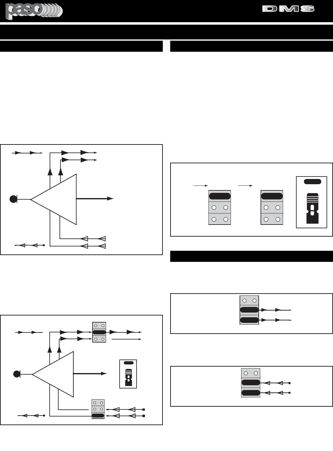
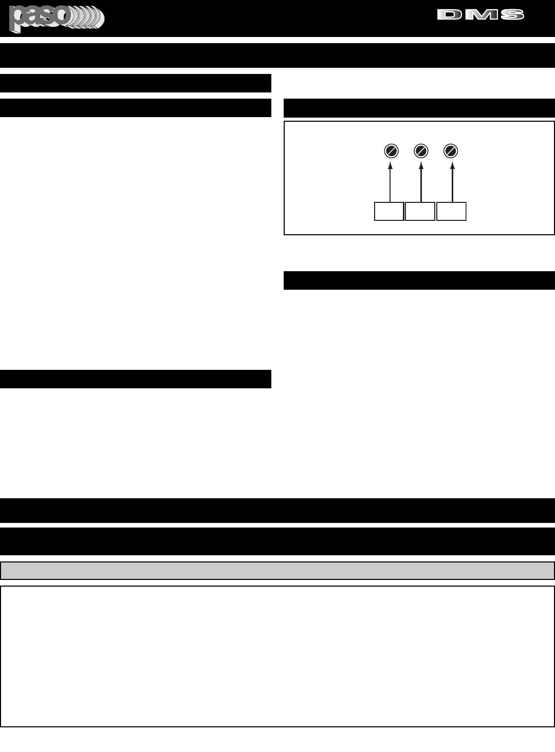
DUAL VOX AND DUAL MUTE - The Amplifier provides two inde-
pendent VOX (V1 & V2) and two MUTE (M1 & M2) SYSTEMS
FUNCTION SOCKETS - EACH INPUT IS PROVIDED WITH A
VOX (V1 & V2) AND A MUTE (M1 & M2) SOCKET.
INPUTS VOX AND MUTE FUNCTION - All Inputs including the
Module provide 2 - VOX SEND and 2 MUTE RECEIVE functions.
The VOX and MUTE functions are SWITCHED-ON, on each Input,
by Internal Jumpers provided for each Input. Two VOX BUSS
SEND (V1 & V2) and two MUTE BUSS RECEIVE (M1 & M2) can
be independently or simultaneously SWITCHED-ON to suit the
application requirement.
Fig. 8 - Any Input VOX and MUTE Functions
JUMPER SETTINGS - The VOX and MUTE Functions are
SWITCHED-ON or OFF by setting the JUMPERS on the VOX (A)
and MUTE (B) SOCKET. See Fig. 8A.
The SOCKETS are located on the Main PCB inside the Amplifier
as shown on the SWITCHES and JUMPERS LOCATION DIA-
GRAM in this Manual. Each Socket is identified by an ID NUMBER
and the FUNCTION and DEFAULT settings are listed on the
FUNCTION SWITCHES and JUMPERS DEFAULT SETTING
TABLE in this Manual.
TO SET: Lift the Jumper and reset as required. making sure that
the JUMPER is properly positioned over the two shorting pins.
The VOX JUMPER has three positions: OFF, V1 and V2
The MUTE JUMPER has three positions: OFF, M1 and M2
V1
V2
OFF
VOX 2 BUSS OFF
M2
M1OFF
X
MUTE 2 BUSS ON
XMUTE 1 BUSS OFF
AUDIO OUT
DMS Anyinput 02
VOX SEND
MUTE RECEIVE
SW215
SW220
JUMPER
ANY
INPUT
SOURCE IN
JUMPER
JUMPER
VOX 2 BUSS ON
Fig. 8B - Any Input VOX 1 and MUTE 2 Activated
JUMPER
OFF
SW215
V 1
V 2
OFF
SW220
M 1
M 2
AB
JUMPER JUMPER
Vox Mute Socket
VOX JUMPERS
SOCKET MUTE JUMPERS
SOCKET
SOCKET
ID NO.
The figure below shows how the VOX 1 Logic Switch and the
MUTE 2 Logic Switch are SWITCHED-ON by moving the Jumpers
from the OFF position to the V 1 and M 2 position. When the Input
is activated by a Source signal the corresponding VOX Signal is
sent to the V1 BUSS.When the VOX 2 is activated by another Input
the MUTE Signal is present on the MUTE 2 BUSS and it will
MUTE this Input
SETTING THE VOX AND MUTE JUMPERS
Fig. 8A - VOX and MUTE Sockets
More than one JUMPER may be used on a VOX SOCKET as
shown below. In this example both the VOX 1 and VOX 2 functions
are SWITCHED -ON when the Input is activated. For this purpose
additional JUMPERS are packed with each Amplifier.
OFF
V 1
V 2
A
JUMPER
Vox Socket 01
VOX SOCKET
JUMPER
VOX 1 BUSS ON
VOX 2 BUSS ON
SETTING MORE THAN ONE FUNCTION
More than one JUMPER may be used on a MUTE SOCKET as
shown below. In this example both the MUTE 1 and MUTE 2 func-
tions will MUTE this INPUT when either VOX 1 or VOX 2 are acti-
vated by other INPUTS.
OFF
M 1
M 2
B
JUMPER
Mute Socket 01
MUTE SOCKET
JUMPER
MUTE 1 BUSS ON
MUTE 2 BUSS ON
NOTE: BE SURE NOT TO SET BOTH THE VOX AND CORRE-
SPONDING MUTE ON THE SAME INPUT OR THE INPUT WILL
MUTE ITSELF WHEN ACTIVATED.
EXAMPLE: INPUT 1 - V 1 and M 1 BOTH ON.
PROFESSIONAL AUDIO & SOUND
®
TM
DIGITAL MUSIC SERIES
DIGITAL MUSIC AMPLIFIERS
PAGE 9
SPECIFICATIONS ARE SUBJECT TO CHANGE WITHOUT NOTICEDMS3040/3080/3120
FUNCTION SETTINGS EXAMPLES
V1
V2
OFF
VOX 2 BUSS OFF
M2
M1OFF
INPUT 1
X
MUTE 2 BUSS OFF
X
X
MUTE 1 BUSS OFF
MIC OUT
MIC IN
VOX SEND
MUTE RECEIVE
SW215
SW220
V1
V2
OFF
VOX 2 BUSS OFF
M2
M1
OFF
INPUT 4
AUX 1
X
MUTE 2 BUSS OFF
X
MUTE 1 BUSS ON
MUSIC OUT
MUSIC
IN
Input 1-4 - V1 - 01
VOX SEND
MUTE RECEIVE
SW212
SW217
VOX 1 BUSS OFF
X
VOX 1 BUSS ON
VOX 1 BUSS MUTE 1 BUSS
VOX 2 BUSS MUTE 2 BUSS
WHEN MIC 1 IS
ACTIVATED THE VOX 1
BUSS IS SWITCHED-ON
AND THE SIGNAL
PRESENT ON THE
MUTE 1 BUSS WILL
MUTE INPUT 4/AUX 1
WHEN MIC 1 IS ACTIVATED
THE VOX 1 BUSS IS
SWITCHED-ON AND THE
SIGNAL PRESENT ON THE
MUTE 1 BUSS WILL MUTE THE
MUSIC FROM INPUT 4/AUX 1
JUMPER
JUMPER
JUMPER
JUMPER
JUMPER
VOX - MUTE JUMPERS SETTING
VOX 1 BUSS MUTE 1 BUSS
VOX 2 BUSS MUTE 2 BUSS
V1
V2
OFF
VOX 2 BUSS OFF
M2
M1
OFF
INPUT 4
AUX 1
X
MUTE 2 BUSS OFF
X
MUTE 1 BUSS ON
MUSIC OUT
MUSIC
IN
Input 1-4 -Tel - 01
VOX SEND
MUTE RECEIVE
SW212
SW217
VOX 1 BUSS OFF
X
WHEN MIC1 OR TEL ARE
ACTIVATED THE VOX 1
BUSS IS SWITCHED-ON
AND THE SIGNAL PRESENT
ON THE MUTE 1 BUSS WILL
MUTE THE MUSIC FROM
INPUT 4/AUX 1
V1
V2
OFF
VOX 2 BUSS ON
M2
M1OFF
INPUT 1
MUTE 2 BUSS OFF
X
X
MUTE 1 BUSS OFF
MIC OUT
MIC IN
VOX SEND
MUTE RECEIVE
SW215
SW220
VOX 1 BUSS ON
WHEN MIC1 IS
ACTIVATED THE VOX 1
BUSS AND THE VOX 2
BUSS ARE SWITCHED-
ON AND THE SIGNALS
PRESENT ON THE
MUTE 1 & 2 BUSS WILL
MUTE THE TEL INPUT
AND INPUT 4/AUX 1
V1
V2
OFF
VOX 2 BUSS OFF
M2
M1OFF
TEL INPUT
X
MUTE 2 BUSS ON
XMUTE 1 BUSS OFF
PHONE OUT
TEL IN
VOX SEND
MUTE RECEIVE
SW214
SW216
VOX 1 BUSS ON
WHEN THE TEL
INPUT IS ACTIVATED
THE VOX 1 BUSS IS
SWITCHED-ON AND
THE SIGNAL
PRESENT ON THE
MUTE 1 BUSS WILL
MUTE INPUT 4/AUX 1
JUMPER
JUMPER
JUMPER
JUMPER
JUMPER
JUMPER
JUMPER
VOX - MUTE JUMPERS SETTING
JUMPER
EXAMPLE 9
VOX 1 BUSS MUTE 1 BUSS
VOX 2 BUSS MUTE 2 BUSS
V1
V2
OFF VOX 1 BUSS OFF
M2
M1 OFF
INPUT 5
AUX 2
X
MUTE 2 BUSS OFF
MUTE 1 BUSS ON
JUKEBOX OUT
JUKEBOX
IN
Input 1-4 -5 - 03
SW212
SW217
VOX 1 BUSS OFF
X
WHEN INPUT 4AUX 1 IS
ACTIVATED THE VOX 2
BUSS IS SWITCHED-ON
AND THE SIGNAL PRESENT
ON THE MUTE 2 BUSS WILL
MUTE THE MUSIC FROM
INPUT 5/AUX 2
V1
V2
OFF
M2
M1OFF
INPUT 1
MUTE 2 BUSS OFF
X
X
MUTE 1 BUSS OFF
MIC OUT
MIC IN
SW215
SW220
VOX 1 BUSS ON
WHEN MIC 1 IS
ACTIVATED THE VOX 1
BUSS AND THE VOX 2
BUSS ARE SWITCHED-
ON AND THE SIGNALS
PRESENT ON THE MUTE
1 & 2 BUSS WILL MUTE
THE INPUT 4/AUX 1 AND
INPUT 5/AUX 2
V1
V2
OFF
VOX 2 BUSS ON
M2
M1OFF
MUTE 2 BUSS ON
XMUTE 1 BUSS ON
MUSIC OUT
INPUT 5/AUX 2 IS
MUTED BY BOTH INPUT
4/AUX 1 AND INPUT 1
WHEN ACTIVATED.
JUMPER
JUMPER
JUMPER
JUMPER
JUMPER
VOX - MUTE JUMPERS SETTING
INPUT 4
AUX 1
MUSIC
IN
JUMPER
VOX 2 BUSS OFF
JUMPER
SW213
SW223
VOX 2 BUSS OFF
X
31
MUTE-2
DELAY
3 to 30 Sec
JUMPER
X
X
EXAMPLE 9B
EXAMPLE 9A
EXAMPLES
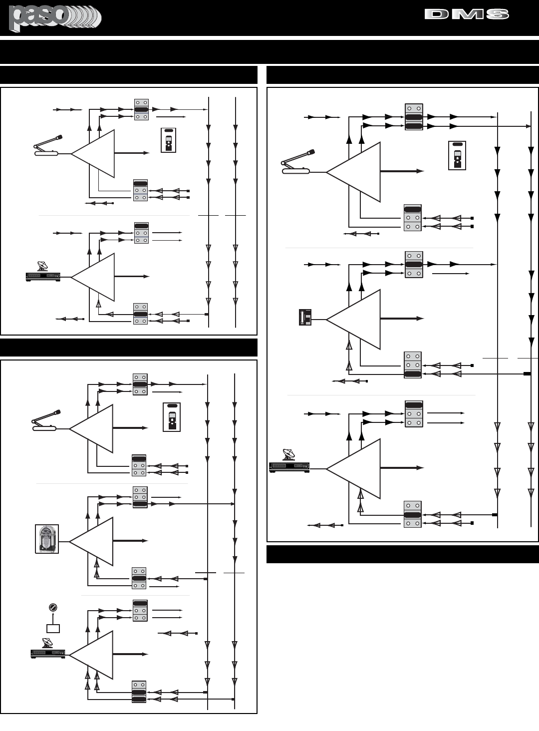
EXAMPLE 9 - INPUT 1 (MIC 1) mutes INPUT 4/AUX 1. When the
Microphone is activated the Music on AUX 1 is muted.
EXAMPLE 9A - INPUT 1 (MIC 1) and TEL IN (Phone Paging) both
mute INPUT 4/AUX 1. When the Microphone or the Phone Paging
are activated the Music on AUX 1 is muted. The Microphone has pri-
ority over the Phone Paging.When MIC 1 is activated both the Phone
Paging and the Music on AUX 1 are muted.
EXAMPLE 9B - INPUT 1 (MIC 1) mutes INPUT 4/AUX 1 and INPUT
5/AUX 2. INPUT 4 (Jukebox) mutes INPUT 5 (Sat. Rcvr). When the
Jukebox is turned-On the Background Music on AUX 2 is muted.
MUTE 2 DELAY (Reference 31) Control is provided.The Microphone
Paging has priority over the Background Music and the Jukebox.
PROFESSIONAL AUDIO & SOUND
®
TM
DIGITAL MUSIC SERIES
DIGITAL MUSIC AMPLIFIERS
PAGE 10 SPECIFICATIONS ARE SUBJECT TO CHANGE WITHOUT NOTICE DMS3040/3080/3120
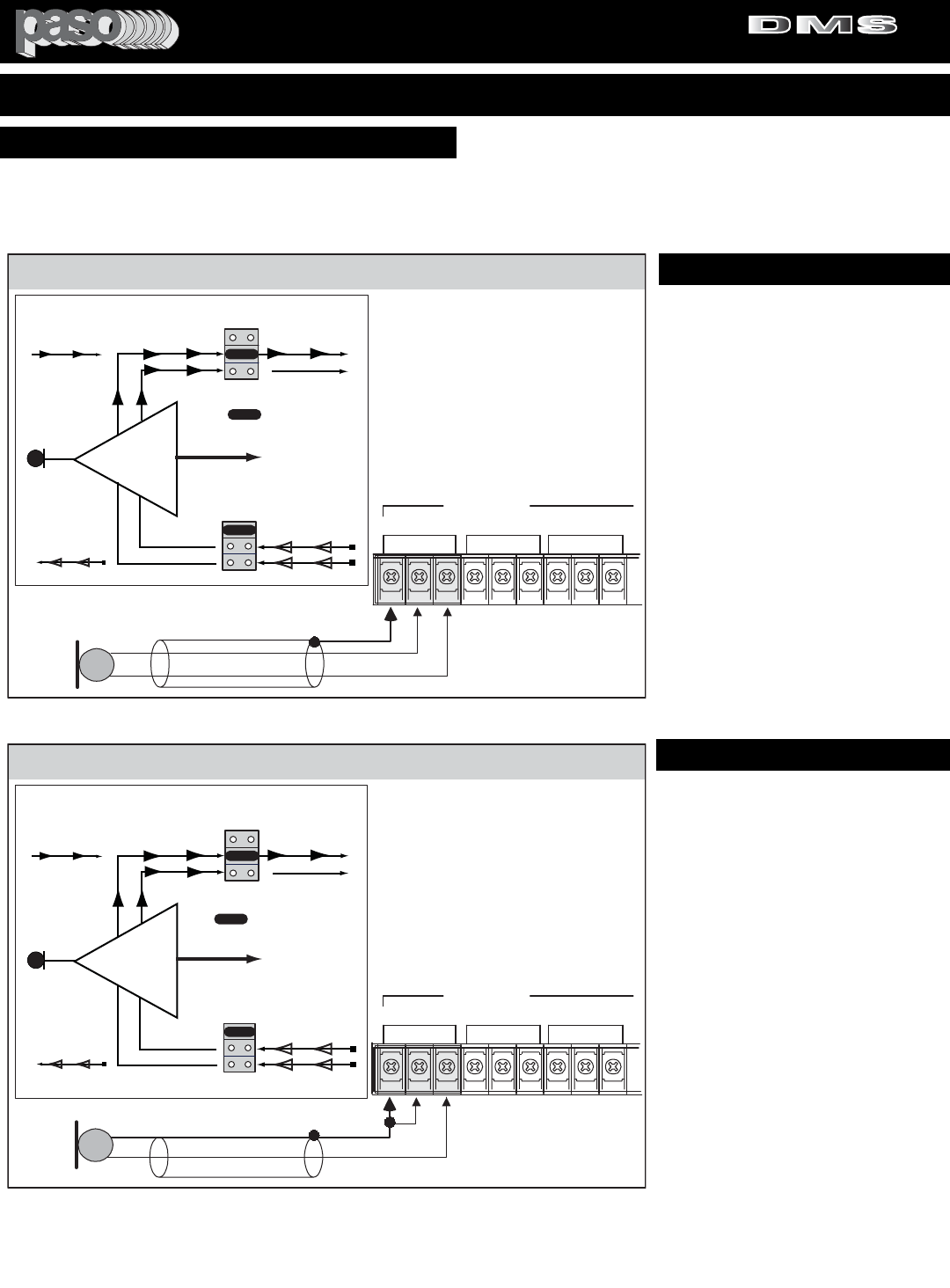
INPUT 1 SETTING AS A MICROPHONE INPUT
MICROPHONE TYPE
The Microphone Input accepts Low Impedance (250-600 ohm)
Dynamic Microphones.The Microphone may be a balanced output
type (three wire) or an unbalanced output type (two wire).
PASO MICROPHONES
All PASO low impedance Microphones have a balanced output for
best performance. Connect the RED lead to terminal HOT, the
WHITE lead to terminal COM and the SHIELD to terminal G.
3120 Micbal 01
THREE LEADS BALANCED MICROPHONE WIRING
SHIELD
MIC
Lo Z RED
WHITE
INPUT 1 - Default Jumper Settings
INPUT 3 (MIC)
INPUT 2 (MIC)
INPUT 1 (MIC)
G COM HOT G COM HOT G COM HOT
BALANCED
250ohm 1.5mV
The Diagram at Left shows the
Default Settings for INPUT 1.
VOX 1 is SWITCHED ON
VOX 2 is SWITCHED OFF
MUTE 1 is SWITCHED OFF
MUTE 2 is SWITCHED OFF
When the INPUT 1 (MIC 1) is
activated the VOX 1 BUSS is ON
and it will MUTE any Input with the
MUTE 1 Setting SWITCHED ON.
NOTE: To change the
INPUT Default Settings
refer to the appropriate
section in this Manual
The microphone leads color refers to Paso Microphones only.
When using other brand refer to instructions packed with that
unit.
V1
V2
OFF VOX 1 BUSS
ACTIVATED
VOX 2 BUSS OFF
M2
M1 OFF
INPUT 1
X
MUTE 2 BUSS OFF
X
X
MUTE 1 BUSS OFF
AUDIO OUT
MIC IN
Input 1 - V1 - 01
VOX SEND
MUTE RECEIVE
SW215
SW220
JUMPER
JUMPER
VOX - MUTE JUMPERS SETTING
= JUMPER
JUMPER
TWO LEADS UNBALANCED MICROPHONE WIRING
INPUT 1 - Default Jumper Settings
INPUT 3 (MIC)
INPUT 2 (MIC)
INPUT 1 (MIC)
G COM HOT G COM HOT G COM HOT
BALANCED
250ohm 1.5mV
The Diagram at Left shows the
Default Settings for INPUT 1.
VOX 1 is SWITCHED ON
VOX 2 is SWITCHED OFF
MUTE 1 is SWITCHED OFF
MUTE 2 is SWITCHED OFF
When the INPUT 1 (MIC 1) is
activated the VOX 1 BUSS is ON
and it will MUTE any Input with the
MUTE 1 Setting SWITCHED ON.
NOTE: To change the
INPUT Default Settings
refer to the appropriate
section in this Manual
SHIELD
MIC
Lo Z HOT LEAD 3120 Micunbal 01
V1
V2
OFF VOX 1 BUSS
ACTIVATED
VOX 2 BUSS OFF
M2
M1 OFF
INPUT 1
X
MUTE 2 BUSS OFF
X
X
MUTE 1 BUSS OFF
AUDIO OUT
MIC IN
Input 1 - V1 - 01
VOX SEND
MUTE RECEIVE
SW215
SW220
= JUMPER
JUMPER
JUMPER
JUMPER
VOX - MUTE JUMPERS SETTING
WIRING
CABLE
MICROPHONE INPUT
Attach the microphone leads to the ter-
minal strip as per diagrams at left.
DO NOT GROUND THE MICROPHONE
CABLE SHIELD TO THE CHASSIS OF
THE AMPLIFIER
BALANCED MICROPHONE
IMPORTANT NOTE: The use of an
unbalanced Microphone (two leads) is
not recommended. For best results in a
PA Application always use a
Unidirectional Dynamic, Low
Impedance, Balanced Microphone
(three leads).
UNBALANCED MICROPHONE
Attach the Microphone leads to the ter-
minal strip as per diagram in Fig 8A. The
cable length should not exceed: 15 Ft.
(4.5 m).
Fig. 10 - Balanced Microphone Input 1 Wiring
CAUTION:
TO PREVENT POSSIBLE DAMAGE TO SPEAKERS OR THE AMPLIFIER
ALL INPUT CONNECTIONS MUST BE MADE WITH THE AMPLIFIER POWER OFF.
CABLE LENGTH - If the distance
between the Microphone and the
Amplifier Input is greater than 15 ft (4.5
m) a Balanced Microphone must be
used. Use a two conductor shielded wire
and connect Microphone to Amplifier as
per Diagram in Fig. 10.
MICROPHONE CABLE ROUTING - The
Microphone Cable should be carefully
routed. Improper Cable routing will
cause spurious oscillations, regenerative
noises, hum, etc. that may permanently
damage the Amplifier.
zDo not route cable next to power
lines.
zDo not route cable near or over
Fluorescent Fixtures.
zDo not route cable next to
Speaker Wires.
zDo not install cable inside Power
Line Conduits.
zAvoid the use of staples that may
penetrate the cable.
Fig. 10A - Unbalanced Microphone Input 1 Wiring
INSTALLATION AND WIRING
PROFESSIONAL AUDIO & SOUND
®
TM
DIGITAL MUSIC SERIES
DIGITAL MUSIC AMPLIFIERS
PAGE 11
SPECIFICATIONS ARE SUBJECT TO CHANGE WITHOUT NOTICEDMS3040/3080/3120
INSTALLATION AND WIRING
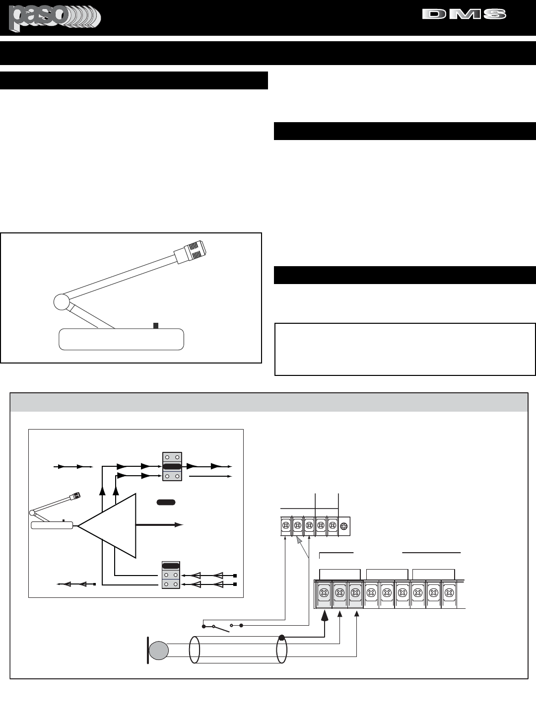
USING A PUSH-TO-TALK DESK BASE MICROPHONE
Microphone paging and precedence over AUX 1 or AUX 2 channels
may be accomplished by using a Desk Base or a Gooseneck
Microphone. Wire the Microphone output leads to the MIC input ter-
minals as per Fig. 11A.
MUTING: The Amplifier is equipped with two independent Muting
Circuits:
zDirect Muting by shorting the MUTE Terminals
zAutomatic Muting with VOX - Voice Activated Muting
For additional information on the Muting operation refer
to the Muting Functions section of this Manual.
WIRING
3120 Micbase 01
INPUT 1 - Default Jumper Settings
INPUT 3 (MIC)
INPUT 2 (MIC)
INPUT 1 (MIC)
G COM HOT G COM HOT G COM HOT
BALANCED
250ohm 1.5mV
The Diagram at Left shows the
Default Settings for INPUT 1.
VOX 1 is SWITCHED ON
VOX 2 is SWITCHED OFF
MUTE 1 is SWITCHED OFF
MUTE 2 is SWITCHED OFF
When the INPUT 1 (MIC 1) is
activated the VOX 1 BUSS is ON
and it will MUTE any Input with the
MUTE 1 Setting SWITCHED ON.
NOTE: To change the
INPUT Default Settings
refer to the appropriate
section in this Manual
V1
V2
OFF VOX 1 BUSS
ACTIVATED
VOX 2 BUSS OFF
M2
M1 OFF
INPUT 1
X
MUTE 2 BUSS OFF
X
X
MUTE 1 BUSS OFF
AUDIO OUT
MIC IN
VOX SEND
MUTE RECEIVE
SW215
SW220
= JUMPER
JUMPER
JUMPER
VOX - MUTE JUMPERS SETTING
GM2
M1 RVC
GROUND
MUTE 1
MUTE 2
MASTER
REMOTE
VOLUME
RVC
SHIELD
MIC
Lo Z
B
A
MUTING SWITCH
Connect Desk Base or Gooseneck
Microphone as per diagram below.
Connect Muting Switch to MUTE 1
or MUTE 2 and G Terminals.
If using the VOX system the
muting switch is unnecessary.
Push to Talk Key
DESK BASE/GOOSENECK MICROPHONE WITH MUTING SWITCH
Fig. 11A - Input 1 and Muting Terminals
Wire the Desk Base Microphone leads to the Microphone
Input terminal strip as per diagram in Fig 11A. Check
Microphone instructions and connect HOT LEAD (B) to
Terminal HOT, COMMON LEAD (A) to Terminal COM and
SHIELD LEAD to Terminal G. Connect Muting Switch to
Terminals MUTE 1 or MUTE 2 and G as shown.
DO NOT GROUND THE MICROPHONE CABLE SHIELD
TO THE CHASSIS OF THE AMPLIFIER
b50side
b50side
Push to Talk Key
Push to Talk Key
Fig. 11 - Desk Base Microphone
INPUT 1 - USING A DESK BASE MICROPHONE
MUTING - PRIORITY SETTINGS
MUTING INPUT 4/AUX 1 (MUSIC INPUT)
To mute Input 4/AUX 1 (Music Input) when Paging from MIC 1, set INPUT
4/AUX 1 MUTE 1 JUMPER to ON Position. Each time MIC 1 is activated
the Program on Input 4/AUX 1 is automatically muted by the VOX.
Direct Muting is provided by the Desk Base Muting Switch wired as
per diagram in Fig. 11A. If Auto-Mute (VOX) is desired follow instruc-
tions below. The Desk Base Muting Switch can be omitted.
CAUTION:
TO PREVENT POSSIBLE DAMAGE TO SPEAKERS
OR THE AMPLIFIER ALL INPUT CONNECTIONS MUST BE
MADE WITH THE AMPLIFIER POWER OFF.
PROFESSIONAL AUDIO & SOUND
®
TM
DIGITAL MUSIC SERIES
DIGITAL MUSIC AMPLIFIERS

PAGE 12 SPECIFICATIONS ARE SUBJECT TO CHANGE WITHOUT NOTICE DMS3040/3080/3120
INPUT CONNECTIONS
CONFIGURATION TABLES
CONDENSER AND ELECTRET TYPE MICROPHONES
Condenser and Electret Microphones require a DC Operating
Voltage. The Amplifier provides this operating voltage or Phantom
Power selectively on Inputs.1-2-3-4-5.
Prior to selecting the Condenser or Electret Microphone be sure
that the Operating Voltage and Output Impedance of the device
match the Input characteristics of the Amplifier listed below.
Phantom Power = 18 Volt DC
Input Impedance = 250 to 600 ohm
ACCESS TO PHANTOM POWER SELECTORS
1) Remove Power Cord from AC Outlet.
2) Remove the three screws on each side of the Amplifier.
3) Lift Cover and carefully slide Cover out towards the rear.
4) Jumpers are located on the Main Printed Circuit Board.
Fig. 12 - Balanced Condenser/Electret Microphone Wiring - Configuration Tables
THE FOLLOWING INSTRUCTIONS REQUIRE THE REMOVAL OF THE AMPLIFIER PROTECTIVE COVER AND ARE
PROVIDED FOR USE BY QUALIFIED PERSONNEL ONLY.
TO AVOID THE RISK OF ELECTRICAL SHOCK DO NOT PERFORM ANY INSTALLATION OR SERVICING UNLESS YOU
ARE QUALIFIED TO DO SO. REFER INSTALLATION OR SERVICING TO QUALIFIED PERSONNEL.
CAUTION ! REMOVAL OF THE AMPLIFIER COVER PRESENTS AN ELECTRICAL SHOCK HAZARD
ALWAYS REMOVE THE POWER CORD FROM THE AC WALL OUTLET
3120 Micbal Electret
BALANCED CONDENSER/ELECTRET MICROPHONE WIRING
SHIELD
MIC
Lo Z
INPUT 3 (MIC)
INPUT 2 (MIC)
INPUT 1 (MIC)
G COM HOT G COM HOT G COM HOT
BALANCED
250ohm 1.5mV
MIC INPUTS PHANTOM POWER JUMPER SETTING
WHEN USING ELECTRET MICROPHONES
-0 +18V +18V
INPUT 1- 2 - 3 - 4 - 5 DEFAULT
JUMPER SETTINGS
Input Jumper No. Setting
INPUT 1 SW201 OFF
INPUT 2 SW202 OFF
INPUT 3 SW203 OFF
INPUT 4 SW204 OFF
INPUT 5 SW207 OFF
SW201
OFF
JUMPER
On
SW202
OFF
JUMPER
On
SW203
OFF
JUMPER
On
SW204
OFF
JUMPER
On
INPUT 1
INPUT 2
INPUT 3
INPUT 4 (When set as MIC 4)
HOT LEAD
HOT LEAD
SW207
OFF
JUMPER
On
INPUT 5 (When set as MIC 5)
Input Switch No. Setting
INPUT 4 SW228 AUX 1
INPUT 5 SW208 AUX 2
INPUT 5 SW229 AUX 2
INPUT 4 - 5 DEFAULT
SWITCH SETTINGS
Input Switch No. Setting
INPUT 4 SW228 MIC 4
INPUT 5 SW208 MIC 5
INPUT 5 SW229 MIC 5
INPUT 4 - 5 SWITCH SETTINGS WHEN
CONFIGURING AS MICROPHONE INPUT
CONDENSER AND ELECTRET MICROPHONES
WIRING
PHANTOM POWER SELECTOR JUMPER
By following the Main Printed Board Layout locate the Selector
Jumpers with the ID No. as indicated on the Table below.
Reset the Phantom Power Jumpers for INPUT 1 - 2 or 3 to the ON
position as desired. Lift the Mini Jumper out of the socket pins and
re-position to the ON position. Make sure the Jumper is lined up
with the socket pins.
INPUT 4 and 5 CONFIGURED AS MIC INPUTS
If INPUT 4 and INPUT5 need to be configured as Microphone
Inputs, reset the Phantom Power Jumpers as well as the
Switches provided for the two Inputs as indicated in the Table
below.
PHANTOM POWER SELECTORS
CONDENSER/ELECTRET MICROPHONE
Carefully follow the wiring instruction packed with the Microphone
used. Attach the microphone leads to the terminal strip as per dia-
gram per Fig. below.
DO NOT GROUND THE MICROPHONE CABLE SHIELD TO THE
CHASSIS OF THE AMPLIFIER
PROFESSIONAL AUDIO & SOUND
®
TM
DIGITAL MUSIC SERIES
DIGITAL MUSIC AMPLIFIERS
PAGE 13
SPECIFICATIONS ARE SUBJECT TO CHANGE WITHOUT NOTICEDMS3040/3080/3120
3120 Telpaging 01
BALANCED TELEPHONE PAGING WIRING
TIP
RING
TEL INPUT - Default Jumper Settings
TEL
G COM HOT
BALANCED
600 ohm 100 mV
The Diagram at Left shows the
Default Settings for TEL INPUT.
VOX 1 is SWITCHED ON
VOX 2 is SWITCHED OFF
MUTE 1 is SWITCHED OFF
MUTE 2 is SWITCHED OFF
When the TEL INPUT (PHONE) is
activated the VOX 1 BUSS is ON
and it will MUTE any Input with the
MUTE 1 Setting SWITCHED ON.
NOTE: To change the
INPUT Default Settings
refer to the appropriate
section in this Manual
Telephone System
Paging Output
V1
V2
OFF VOX 1 BUSS
ACTIVATED
VOX 2 BUSS OFF
M2
M1 OFF
X
MUTE 2 BUSS OFF
X
X
MUTE 1 BUSS OFF
PAGING OUT
VOX SEND
MUTE RECEIVE
SW214
SW216
= JUMPER
TEL INPUT
TEL IN
JUMPER
JUMPER
JUMPER
VOX - MUTE JUMPERS SETTING
Fig. 13A - Balanced Telephone Input Wiring
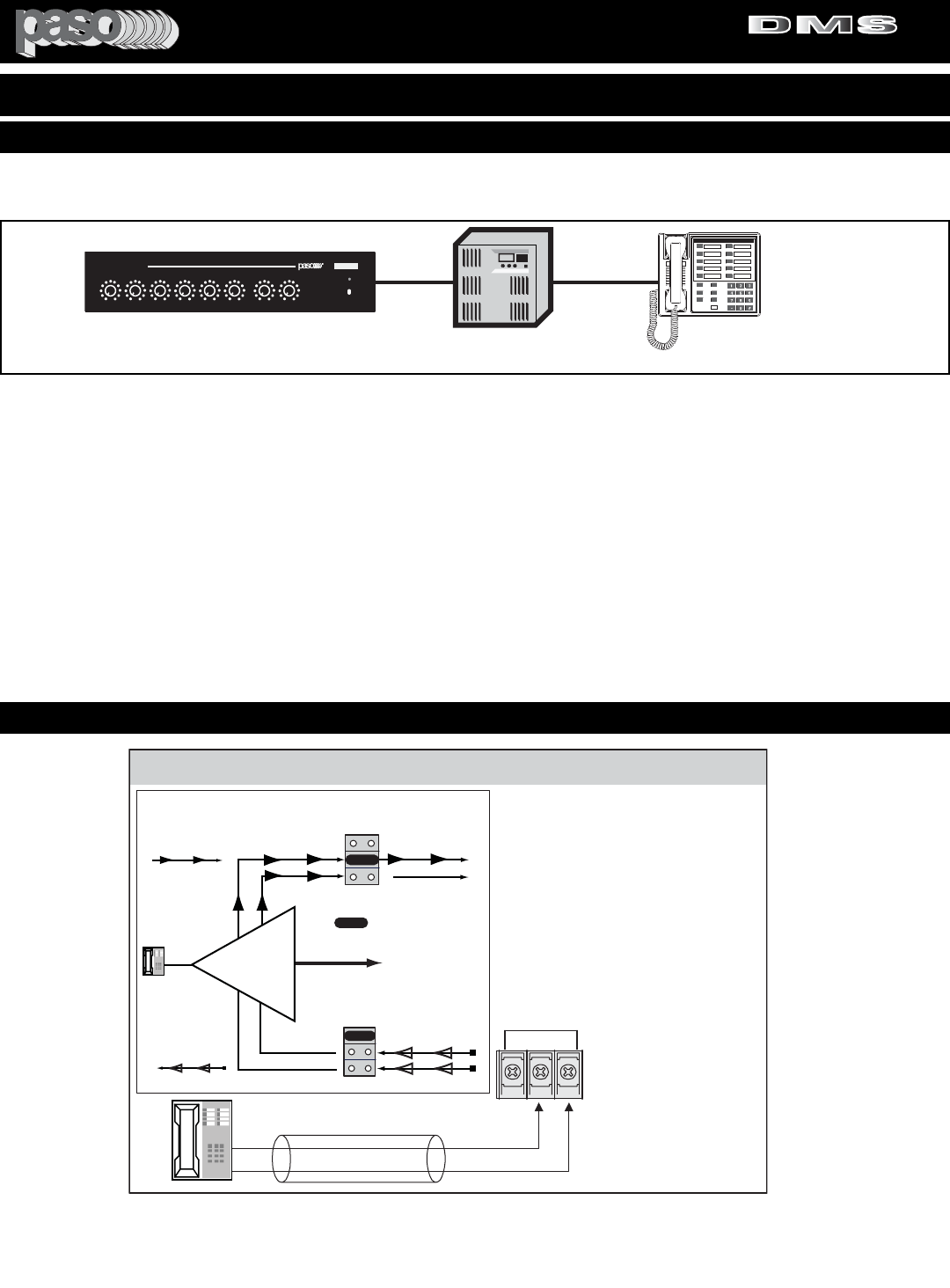
WIRING - The Amplifier is interface ready for the Telephone
line in applications requiring paging from the telephone sys-
tem. The Telephone line Paging Output (Tip and Ring) can
be directly connected to the TEL input and to the HOT and
COM as shown in the wiring diagram Fig. 12A
.
CABLE - Use a two conductor twisted wire.
NOTE: The Telephone Paging Input is a Transformer
Balanced 600 ohm input.
DO NOT GROUND THE TIP OR RING WIRE TO THE
CHASSIS OF THE AMPLIFIER
OUTPUT LEVEL CONTROL - Use TEL OUTPUT LEVEL
Control located on the Rear panel. After wiring adjust con-
trol for the desired output level.
VOICE ACTIVATED MUTING (VOX) - Muting of the AUX 1
channel (music muting) during Paging is automatic via the
Voice Activated Muting System. No contact closure for the
Muting Circuit is required from the Telephone system. For
additional information on the Muting operation refer to the
Muting Functions section of this Manual.
PHONE PAGING PRIORITY OVER MICROPHONES -
Priority over any Microphone Input may be accomplished by
setting the MIC Inputs MUTE Jumpers.
KSU
Key Service Unit
telpagin
Telephone
DMS Amplifier
DIGITAL MUSIC AMPLIFIER
O
POWER
PROFESSIONAL AUDIO & SOUND
DIGITAL MUSIC SERIES
TM
OUTPUT LEVEL
PEAK
INPUT 1 INPUT 2 INPUT 3 INPUT 4/AUX 1 INPUT 5/AUX 2 BASS TREBLEMODULE
100100100100100100+10-10 +10-10
DMS
TEL
INSTALLATION AND WIRING
Fig. 13 - Connecting to the Telephone Paging KSU
CAUTION:
TO PREVENT POSSIBLE DAMAGE TO SPEAKERS OR THE AMPLIFIER ALL INPUT CONNECTIONS MUST BE MADE
WITH THE AMPLIFIER OFF (POWER OFF).
PAGING FROM THE TELEPHONE SYSTEM
TELEPHONE SYSTEM PAGING WIRING
PROFESSIONAL AUDIO & SOUND
®
TM
DIGITAL MUSIC SERIES
DIGITAL MUSIC AMPLIFIERS
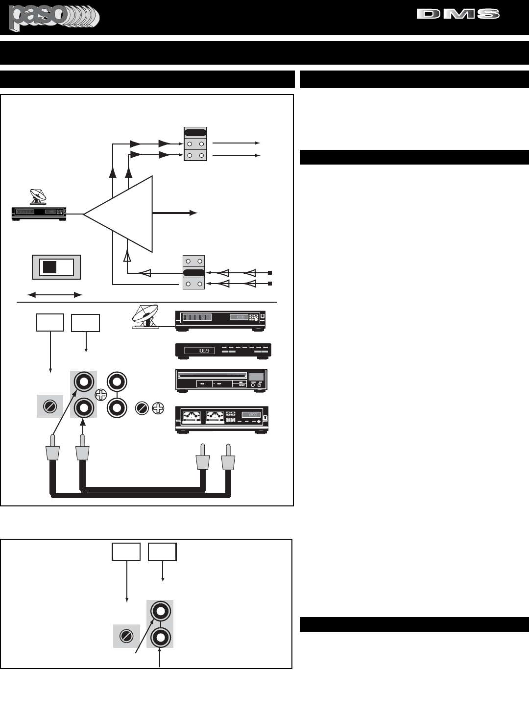
INPUT 4 SET AS AUX 1 (Reference. 19)
The AUX 1 input is provided for high level program source.
The output from a Satellite Receiver, Tuner, Tape Cassette
Deck, CD Player or other high level program source may
be directly connected to this input.
AUX 1 SENSITIVITY ATTENUATOR (Reference. 18)
The AUX 1 Input is equipped with a Sensitivity Attenuator
that allows the interface of the Input with Devices having a
wide range of Output Levels.
TYPICAL OUTPUT LEVEL OF MUSIC DEVICES:
Satellite Receivers = 1 to 5 Volt
Digital Tuners/Receivers = 100 to 300 Mv
CD Players/Changers = 2 to 3 Volt
Tape Decks = 500 to 700 Mv
By adjusting the Input Sensitivity to the level that matches
the device used the correct interface with the Amplifier is
achieved resulting in lower overall distortion and better fre-
quency response characteristics.
SETTING THE AUX 1 INPUT ATTENUATOR
Connect a Music Source to the Amplifier.
Turn Attenuator (rear panel) fully counterclockwise.
Turn INPUT 4 Front Panel Control to midway.
Switch Amplifier and Music Source ON.
Turn Attenuator Control (rear panel) until desired Output
Level is achieved.
Adjust INPUT 4 Front Panel Level Control Up-Down as
desired.
STEREO SUMMING
Most Music Source Devices provide a Stereo Output.
Accordingly the Amplifier is equipped with two Jacks for the
AUX 1 Input (L and R). The two Inputs are internally
buffered and electronically mixed to Mono. This system
ensures that the Music Device is properly loaded and that
the Stereo Signals are correctly summed (L+R) to Mono
without distortion.
CABLE
To connect the music source devices to the AUX 1 Input
use two single conductor shielded audio cable terminated
in a single prong phono plug on both ends.
RMUSIC OUTPUT
LLR
SATELLITE RECEIVER
paso
AM/FM TUNER
CD PLAYER
CD
TAPE DECK
TRACK 01
AUX 1
ATTENUATOR
3120 Aux1 01
R
L
ATTENUATOR
(AUX2)
INPUT 5
MIC-AUX2
BY INTERNAL
SWITCH
47kohm 100mV
INPUT-5(AUX2)
INPUT - 4 (AUX1)
47 kohm 100 mV
18 19
V1
V2
OFF
VOX 2 BUSS OFF
M2
M1
OFF
INPUT 4
AUX 1
X
MUTE 2 BUSS OFF
X
MUTE 1 BUSS ON
MUSIC OUT
MUSIC
IN
Input 1-4 - V1 - 01
SW212
SW217
VOX 1 BUSS OFF
X
WHEN MIC 1 IS
ACTIVATED THE VOX 1
BUSS IS SWITCHED-ON
AND THE SIGNAL
PRESENT ON THE
MUTE 1 BUSS WILL
MUTE THE MUSIC
FROM INPUT 4/AUX 1
JUMPER
JUMPER
AUX 1 MIC 4
SW228
AUX 1 - MIC 4 SWITCH
DEFAULT JUMPERS AND SWITCH SETTING
SW212 = OFF
SW217 = M 1
SW228 = AUX 1
Fig. 14 - Rear Panel AUX 1 Input Diagram
AUX 1
AUX 1 INPUT MUTING
AUX 1
ATTENUATOR
3120 Stereo Summ
INPUT - 4 (AUX1)
47 kohm 100 mV
18 19
L
R
Fig. 14A - Stereo Summing and AUX 1 Input Attenuator
MUTING - WHEN MIC 1 OR THE TEL IN ARE ACTI-
VATED THE VOX 1 BUSS IS SWITCHED-ON AND
THE SIGNAL PRESENT ON THE MUTE 1 BUSS
WILL MUTE THE MUSIC FROM AUX 1.
SETTING INPUT 4 AS AUX 1 INPUT 4/AUX 1 DEFAULT SETTING
JUMPERS/SWITCH NO. FACTORY SETTING
SW212 - VOX JUMPER = OFF
SW217 - MUTE JUMPER = M 1
SW228 - AUX1-MIC4 SWITCH = AUX 1
PAGE 14 SPECIFICATIONS ARE SUBJECT TO CHANGE WITHOUT NOTICE DMS3040/3080/3120
INSTALLATION AND WIRING
PROFESSIONAL AUDIO & SOUND
®
TM
DIGITAL MUSIC SERIES
DIGITAL MUSIC AMPLIFIERS
PAGE 15
SPECIFICATIONS ARE SUBJECT TO CHANGE WITHOUT NOTICEDMS3040/3080/3120
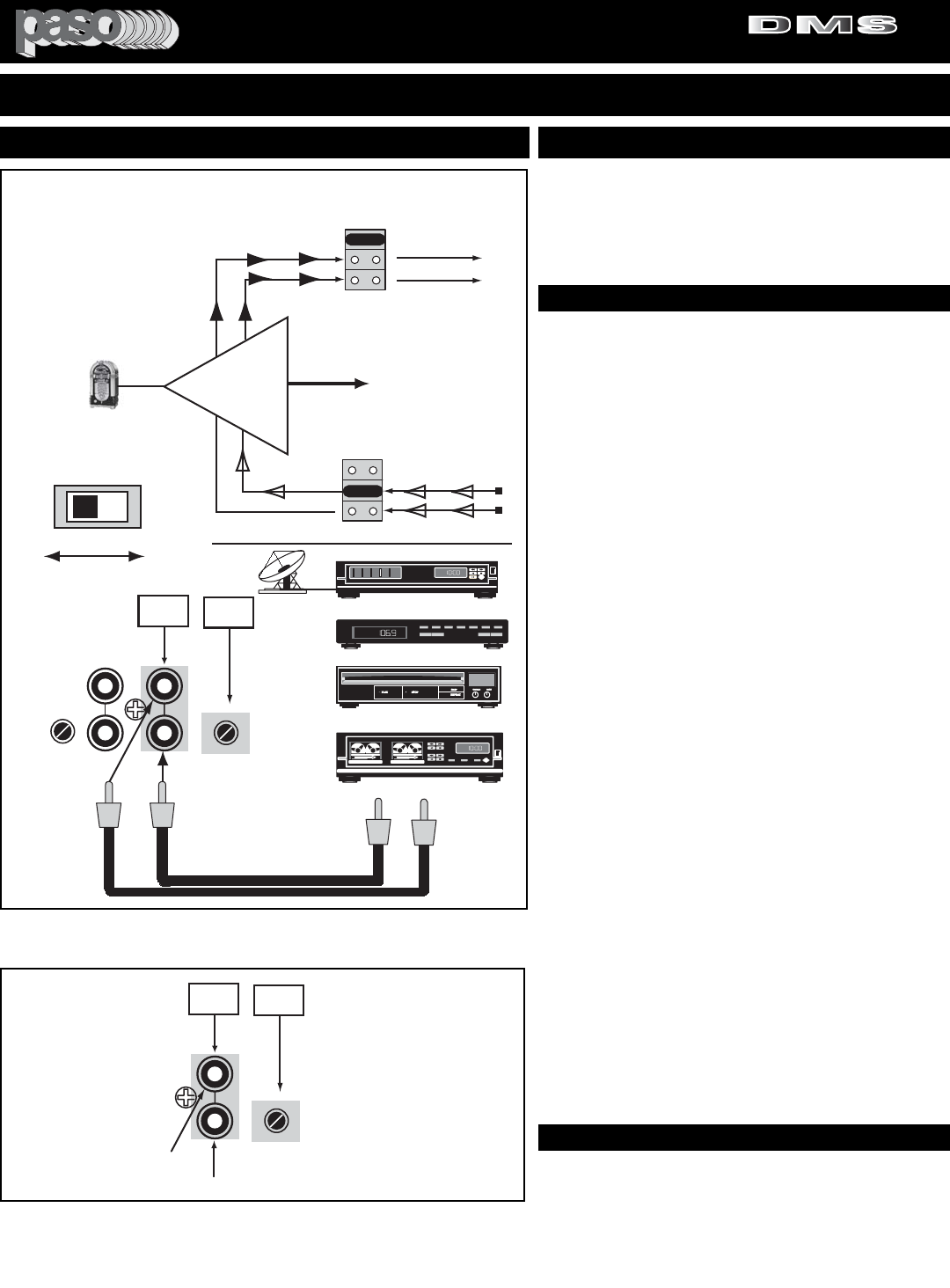
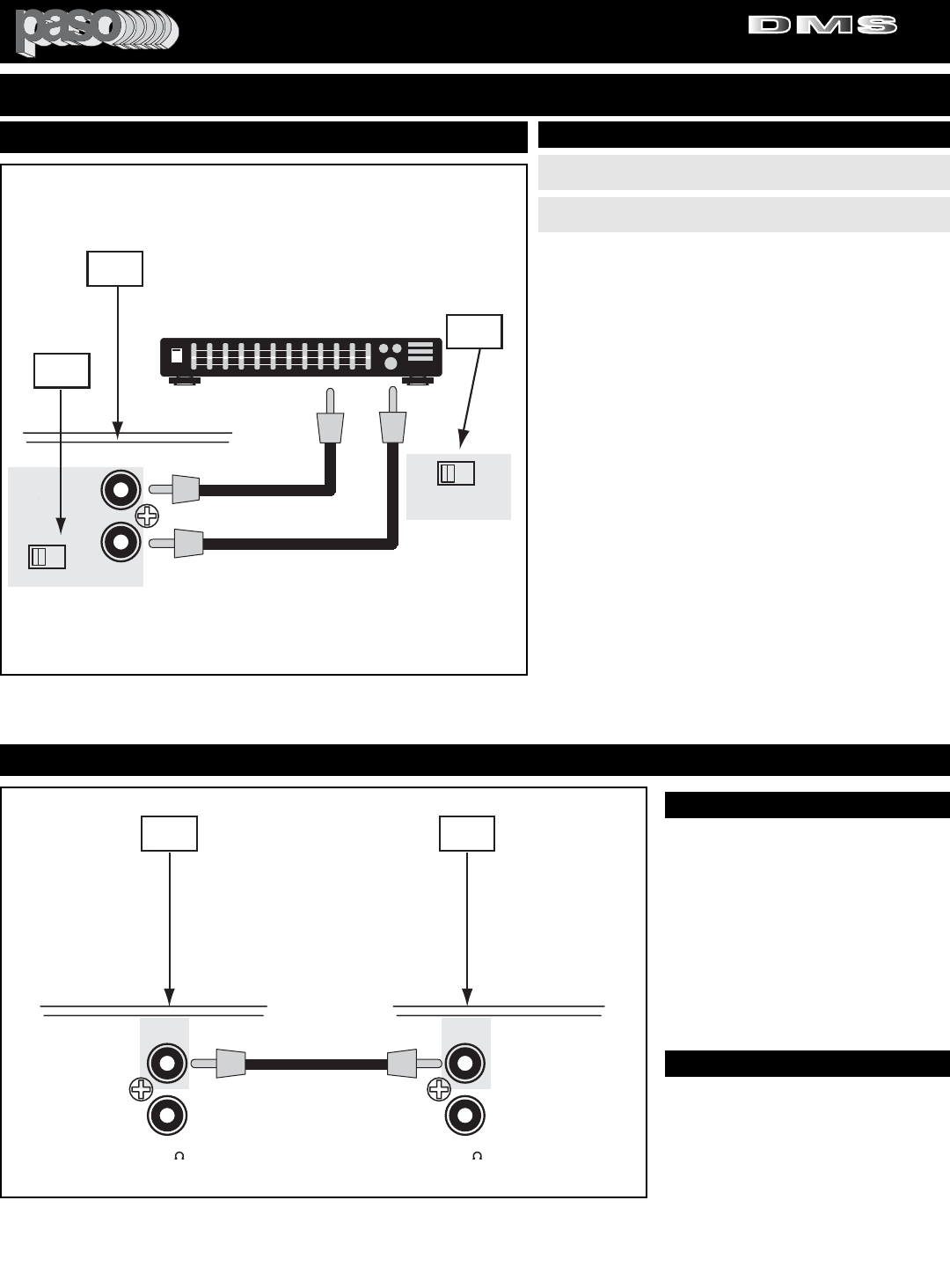
INPUT 5 SET AS AUX 2 (Reference. 20)
The AUX 2 input is provided for high level program source.
The output from a Jukebox, Tuner, Tape Cassette Deck,
CD Player or other high level program source may be
directly connected to this input.
AUX 2 SENSITIVITY ATTENUATOR (Reference. 21)
The AUX 2 Input is equipped with a Sensitivity Attenuator
that allows the interface of the Input with Devices having a
wide range of Output Levels.
TYPICAL OUTPUT LEVEL OF MUSIC DEVICES:
Satellite Receivers = 1 to 5 Volt
Digital Tuners/Receivers = 100 to 300 Mv
CD Players/Changers = 2 to 3 Volt
Tape Decks = 500 to 700 Mv
By adjusting the Input Sensitivity to the level that matches
the device used the correct interface with the Amplifier is
achieved resulting in lower overall distortion and better fre-
quency response characteristics.
SETTING THE AUX 2 INPUT ATTENUATOR
Connect a Music Source to the Amplifier.
Turn Attenuator (rear panel) fully counterclockwise.
Turn INPUT 5 Front Panel Control to midway.
Switch Amplifier and Music Source ON.
Turn Attenuator Control (rear panel) until desired Output
Level is achieved.
Adjust INPUT 5 Front Panel Level Control Up-Down as
desired.
STEREO SUMMING
Most Music Source Devices provide a Stereo Output.
Accordingly the Amplifier is equipped with two Jacks for the
AUX 1 Input (L and R). The two Inputs are internally
buffered and electronically mixed to Mono. This system
ensures that the Music Device is properly loaded and that
the Stereo Signals are correctly summed (L+R) to Mono
without distortion.
CABLE
To connect the music source devices to the AUX 1 Input
use two single conductor shielded audio cable terminated
in a single prong phono plug on both ends.
RMUSIC OUTPUT
LLR
AUX 1
ATTENUATOR
3120 Aux2 01
R
L
INPUT 5
MIC-AUX2
BY INTERNAL
SWITCH
INPUT - 4 (AUX1)
47 kohm 100 mV
21
20
V1
V2
OFF
VOX 2 BUSS OFF
M2
M1
OFF
INPUT 5
AUX 2
X
MUTE 2 BUSS OFF
X
MUTE 1 BUSS ON
MUSIC OUT
MUSIC
IN
Input 1-4 - V1 - 01
SW213
SW223
VOX 1 BUSS OFF
X
WHEN MIC 1 IS
ACTIVATED THE VOX 1
BUSS IS SWITCHED-ON
AND THE SIGNAL
PRESENT ON THE
MUTE 1 BUSS WILL
MUTE THE MUSIC
FROM INPUT 5/AUX 2
JUMPER
JUMPER
AUX 2 MIC 5
SW208 and SW229
AUX 2 - MIC 5 SWITCH
DEFAULT JUMPERS AND SWITCH SETTING
SW213 = OFF
SW223 = M 1
SW208 = AUX 2
SW229 = AUX 2
(AUX 2)
ATTENUATOR
INPUT 5 (AUX 2)
47 Kohm 100 mV
SET TO AUX 2
SATELLITE RECEIVER
paso
AM/FM TUNER
CD PLAYER
CD
TAPE DECK
TRACK 01
Fig. 15 - Rear Panel AUX 2 Input Diagram
AUX 2
AUX 2 INPUT MUTING
3120 Stereo Summ 01
R
L
INPUT 5
MIC-AUX2
21
20
(AUX 2)
ATTENUATOR
INPUT 5 (AUX 2)
47 Kohm 100 mV
Fig. 15A - Stereo Summing and AUX 2 Input Attenuator
MUTING - WHEN MIC 1 OR THE TEL IN ARE ACTI-
VATED THE VOX 1 BUSS IS SWITCHED-ON AND
THE SIGNAL PRESENT ON THE MUTE 1 BUSS
WILL MUTE THE MUSIC FROM AUX 2.
SETTING INPUT 5 AS AUX 2 INPUT 5/AUX 2 DEFAULT SETTING
JUMPERS/SWITCH NO. FACTORY SETTING
SW213 - VOX JUMPER = OFF
SW223 - MUTE JUMPER = M 1
SW208 - AUX 2-MIC 5 SWITCH = AUX 2
SW229 - AUX 2-MIC 5 SWITCH = AUX 2
INSTALLATION AND WIRING
PROFESSIONAL AUDIO & SOUND
®
TM
DIGITAL MUSIC SERIES
DIGITAL MUSIC AMPLIFIERS
PAGE 16 SPECIFICATIONS ARE SUBJECT TO CHANGE WITHOUT NOTICE DMS3040/3080/3120
ADDRESSABLE DUAL VOX SYSTEM
DUAL VOX - VOICE ACTIVATED MUTING - The Amplifier
is equipped with a DUAL noiseless, fast acting Logic VOX
Switching System. When any of the INPUTS are activated
and a Signal is present on a given INPUT and either VOX 1
or VOX 2 or BOTH are Switched-ON (using internal
Jumpers) then the MUTE 1 or MUTE 2 BUSS or BOTH are
ACTIVE. If any of the INPUTS have the MUTE 1 or MUTE
2 Switched-ON (by Internal Jumpers) then the INPUT (or
INPUTS) will be MUTED according to the Jumpers Setting.
Once the SIGNAL-ON on the ACTIVE INPUT is terminated
the normal functions are automatically restored on all muted
inputs.
ACCESS TO VOX AND MUTE JUMPERS
REFER TO JUMPERS AND SWITCHES INTERNAL
ACCESS.
CAUTION: PRIOR TO PERFORMING THE ABOVE OPER-
ATION BE SURE TO FOLLOW THE SAFETY NOTES
REFERRING TO THE REMOVAL OF THE AMPLIFIER
COVER.
Fig. 16 - Rear Panel VOX 1 and VOX 2 Sensitivity Control
and MUTE 2 Delay Control
VOX - VOICE ACTIVATED MUTING VOX SENSITIVITY CONTROLS
313233
VOX-1 VOX-2 MUTE-2
SENS
SENS DELAY
DMS3120 Vox Sens 01
VOX SENSITIVITY ADJUSTMENT
1) Turn all Front Panel Input Level Controls to 0.
2) Turn VOX Sensitivity Control counterclockwise until it
stops.
3) Connect a Signal Source (Microphone, Telephone or
Music) to the respective Input Terminals (For connection
details refer to the appropriate section in this Manual).
4) While talking from a Paging Source (Microphone or
Telephone) or Playing Music rotate the INPUT LEVEL CON-
TROLS (Front Panel) until the desired output level is
achieved.
5) While talking from a Paging Source (Microphone or
Telephone) or Playing Music, turn the Sensitivity Control
(VOX 1 or VOX 2) slowly clockwise until the Muting (MUTE
1 or MUTE 2) is activated.
VOX JUMPERS DEFAULT SETTING TABLE
SW210 INPUT 2 - VOX1 - VOX2 - OFF OFF
SW211 INPUT 3 - VOX1 - VOX2 - OFF OFF
SW212 INPUT 4 - VOX1 - VOX2 - OFF OFF
SW213 INPUT 5 - VOX1 - VOX2 - OFF OFF
SW214 TEL IN - VOX1 - VOX2 - OFF V1
SW215 INPUT 1 - VOX1 - VOX2 - OFF V1
SW221 MODULE - VOX1 - VOX2 - OFF OFF
JUMPER JUMPER FUNCTION FACTORY FACTORY
ID NO. REFERENCE DESCRIPTION SETTING SETTING
MAIN PCB JUMPERS
VOX SENSITIVITY CONTROLS
VOX 1 AND VOX 2 SENSITIVITY CONTROLS
The VOX 1 and VOX 2 Sensitivity Controls set the sensitiv-
ity level at which point the VOX 1 and VOX 2 are respective-
ly engaged during INPUT ACTIVATION.The VOX Sensitivity
Controls are located on the Amplifier Rear Panel.
VOX 1 SENSITIVITY CONTROL = Reference 33
VOX 2 SENSITIVITY CONTROL = Reference 32
VOX SENSITIVITY ADJUSTMENT
INSTALLATION AND WIRING
PROFESSIONAL AUDIO & SOUND
®
TM
DIGITAL MUSIC SERIES
DIGITAL MUSIC AMPLIFIERS
PAGE 17
SPECIFICATIONS ARE SUBJECT TO CHANGE WITHOUT NOTICEDMS3040/3080/3120
ADDRESSABLE DUAL MUTING SYSTEM
DIRECT MUTING - Direct Muting may be accomplished by short-
ing the MUTE 1 and MUTE 2 Terminals to the G Terminal through
an external switch. Each time the Muting Switch is closed the cor-
responding MUTE BUSS is activated.
Fig. 17 - Direct Muting Terminals and Diagram
DIRECT MUTING
WIRING
3120 M1 - M2 01
GM2
M1 RVC
GROUND
MUTE 1
MUTE 2
MASTER
REMOTE
VOLUME
RVC
MUTING SWITCH M 2
MUTING SWITCH M 1
10
31
MUTE-2
DELAY
Signal
Level Program
gradually
restored
2-3
sec.
Mute terminals
opened
time
DMS mutfunct 01
Program
Attenuation
60 dB
MUTE 1
Terminals
shorted
Fig. 17B - M 1 Function Timing Diagram
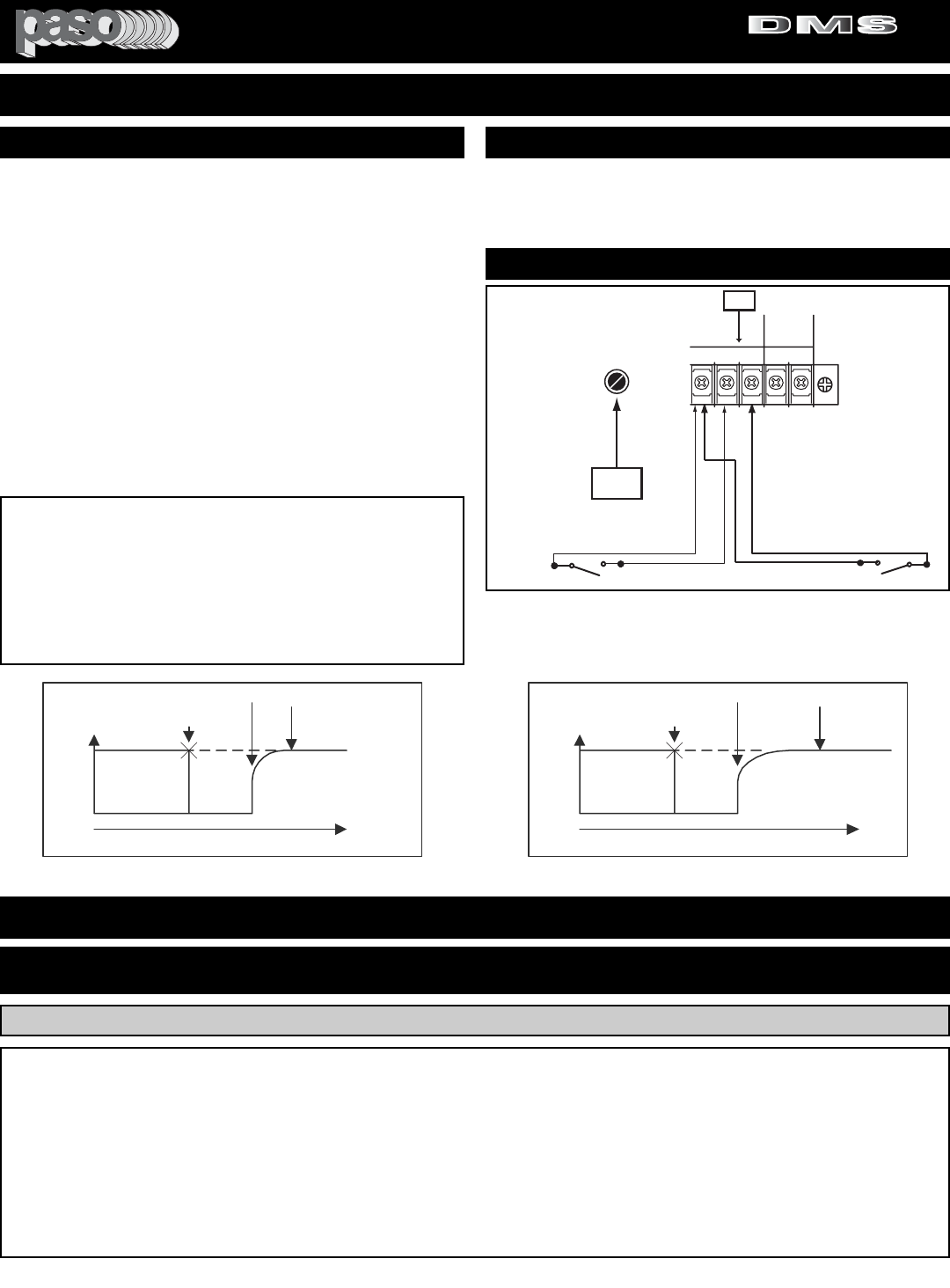
MUTING TIMING - The MUTING is preset for -60 db Attenuation.
When MUTE 1 or 2 are activated the MUTE BUSS is instanta-
neously Switched-ON. When the Muting is deactivated the pro-
gram source is gradually restored.
MUTE 1 (M1) = TIMING PRESET 2-3 SECONDS
MUTE 2 (M2) = TIMING ADJUSTABLE 3-30 SECONDS
MUTE 2 DELAY = USE REAR PANEL CONTROL Reference 31
INSTALLATION AND WIRING
MUTE JUMPERS DEFAULT SETTING TABLE
SW206 VOX RELAY - MUTE 1 - MUTE 2 M1
SW216 TEL IN - MUTE 1 - MUTE 2 - OFF OFF
SW217 INPUT 4/AUX 1 - MUTE 1 - MUTE 2 - OFF M1
SW218 INPUT 3 - MUTE 1 - MUTE 2 - OFF OFF
SW219 INPUT 2 - MUTE 1 - MUTE 2 - OFF OFF
SW220 INPUT 1 - MUTE 1 - MUTE 2 - OFF OFF
SW222 MODULE - MUTE 1 - MUTE 2 - OFF OFF
SW223 INPUT 5/AUX 2 - MUTE 1 - MUTE 2 - OFF M1
SW227 CHIME TRIGGER - MUTE 1 - MUTE 2 M1
JUMPER JUMPER FUNCTION FACTORY FACTORY
ID NO. REFERENCE DESCRIPTION SETTING SETTING
MAIN PCB JUMPERS
DUAL MUTING SYSTEM - The Amplifier is equipped with a DUAL
noiseless, fast acting Logic MUTING Switching System. When any
of the INPUTS are activated and a Signal is present on a given
INPUT and either VOX 1 or VOX 2 or BOTH are Switched-ON
(using internal Jumpers) then the MUTE 1 or MUTE 2 BUSS or
BOTH are ACTIVE. If any of the INPUTS have the MUTE 1 or
MUTE 2 Switched-ON (by Internal Jumpers) then the INPUT (or
INPUTS) will be MUTED according to the Jumpers Setting. Once
the SIGNAL-ON on the ACTIVE INPUT is terminated the normal
functions are automatically restored on all muted inputs.
ACCESS TO MUTE JUMPERS
REFER TO JUMPERS AND SWITCHES INTERNAL ACCESS.
CAUTION: PRIOR TO PERFORMING THE ABOVE OPERATION
BE SURE TO FOLLOW THE SAFETY NOTES REFERRING TO
THE REMOVAL OF THE AMPLIFIER COVER.
Signal
Level
MUTE 2
Terminals
shorted Program
gradually
restored
Adjustable
from
3 to 30
seconds
Mute terminals
opened
time
DMS mutfunct 02
Program
Attenuation
60 dB
Fig. 17C - M 2 Function Timing Diagram
MUTE 2 DELAY - The M 2 Delay can be adjusted by using the
MUTE 2 DELAY CONTROL
on the rear panel (reference 31).
PROFESSIONAL AUDIO & SOUND
®
TM
DIGITAL MUSIC SERIES
DIGITAL MUSIC AMPLIFIERS
PAGE 18 SPECIFICATIONS ARE SUBJECT TO CHANGE WITHOUT NOTICE DMS3040/3080/3120
INSTALLATION AND WIRING
INPUT 1 (MIC 1) UNMUTING FUNCTION
The Input 1 (MIC 1) can be preset to be normally MUTED (INPUT
OFF) when the JUMPER SW205 - MIC 1 UNMUTE - IS SET TO
THE ON POSITION. The MIC 1 is SWITCHED-ON when the
UNMUTE and GTerminals are shorted by a Switch Contact
Closure.This function allows for a multi zone installation using two
or more Amplifiers and a single Microphone and Zone Switches.
When the Jumper SW205 is set to the ON Position the Microphone
Input is OFF and it is turned ON when the UNMUTE and the G ter-
minals are closed by a switch.
JUMPER NO. FUNCTION POSITION SET
SW205 MIC 1 Muted ON
If the Jumper requires resetting follow the instruction below.
ACCESS TO UNMUTING JUMPER
1) Remove Power Cord from AC Outlet.
2) Remove the three screws on each side of the Amplifier
securing the Top Cover to the Chassis.
3) Lift Cover and carefully and slide Cover out towards the rear.
4) On the Main Amplifier Printed Board locate the SW205 -
MIC 1 UNMUTE Jumper Set.
5) Set Jumper to the ON position.
Fig. 18 - Microphone and Zone Unmuting Diagram
THE FOLLOWING INSTRUCTIONS REQUIRE THE REMOVAL OF THE AMPLIFIER PROTECTIVE COVER AND ARE PROVIDED
FOR USE BY QUALIFIED PERSONNEL ONLY. TO AVOID THE RISK OF ELECTRICAL SHOCK DO NOT PERFORM ANY INSTALLA-
TION OR SERVICING UNLESS YOU ARE QUALIFIED TO DO SO.
CAUTION ! REMOVAL OF THE AMPLIFIER COVER PRESENTS AN ELECTRICAL SHOCK HAZARD
ALWAYS REMOVE THE POWER CORD FROM THE AC WALL OUTLET
DIRECT UNMUTING
WIRING
3120 Unmute 01
INPUT 2 (MIC)
INPUT 1 (MIC)
G COM HOT G COM HOT
BALANCED
250ohm 1.5mV
SHIELD
MIC
Lo Z
B
A
ZONE UNMUTING SWITCH
Connect Paging Microphone
as per diagram below
(reference 30). Connect Zone
Unmuting Switch to UNMUTE
(reference 9) and G Terminals.
The VOX (if ON) feature will
automatically mute the Music
MICROPHONE WITH UNMUTING ZONE SWITCH
9
30
MIC1 G M2 M1 RVC
GROUND
UNMUTE
MUTE 1
MUTE 2
MASTER
REMOTE
VOLUME
RVC
A = Common
B = Hot
OFF
SW215
JUMPER
VOX 1 ON
INPUT 1
MIC 1
V1
V2 SW205
OFF
JUMPER
On
MIC 1
UNMUTE OFF
MUTE 1 ON
SW217
JUMPER
INPUT 4
AUX 1
M1
M2
UNMUTE - VOX AND MUTE JUMPER
SETTINGS ON AMPLIFIERS 1 & 2
3120 Unmute Jump Set
Fig. 18A - 2 - Zone System Jumper Settings
21
ZONE 1
2 - ZONE
PAGING SELECTORS
ZONE 2
PAGING MICROPHONE
TO AMP 1
TO AMP 2
3120 2 Zone Diagram 01
TO MIC INPUT
SPST ZONE
SWITCHES
Fig. 18B - 2 - Zone Switching Panel
INPUT 1 (MIC 1) UNMUTING FUNCTION
The Fig. at right shows a typical 2 Zone Switching
Panel. Use SPST Momentary Contact Switches. See
complete 2 - Zone Wiring Diagram provided in this
Manual.
PROFESSIONAL AUDIO & SOUND
®
TM
DIGITAL MUSIC SERIES
DIGITAL MUSIC AMPLIFIERS
PAGE 19
SPECIFICATIONS ARE SUBJECT TO CHANGE WITHOUT NOTICEDMS3040/3080/3120
INSTALLATION AND WIRING
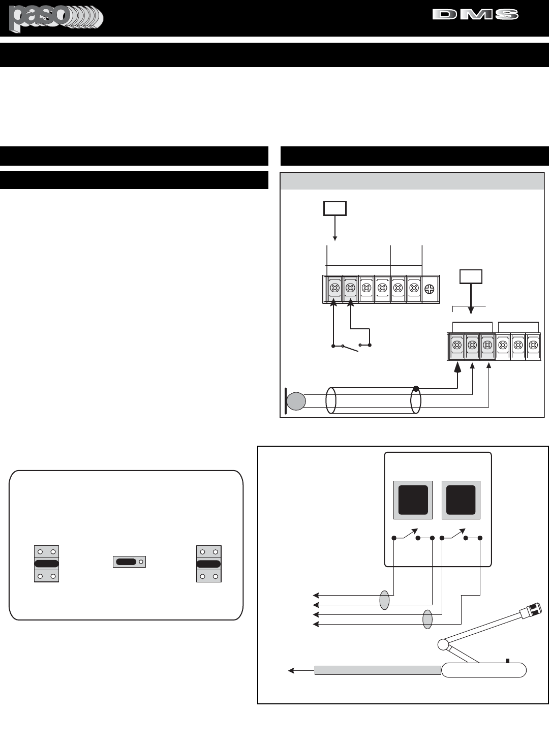
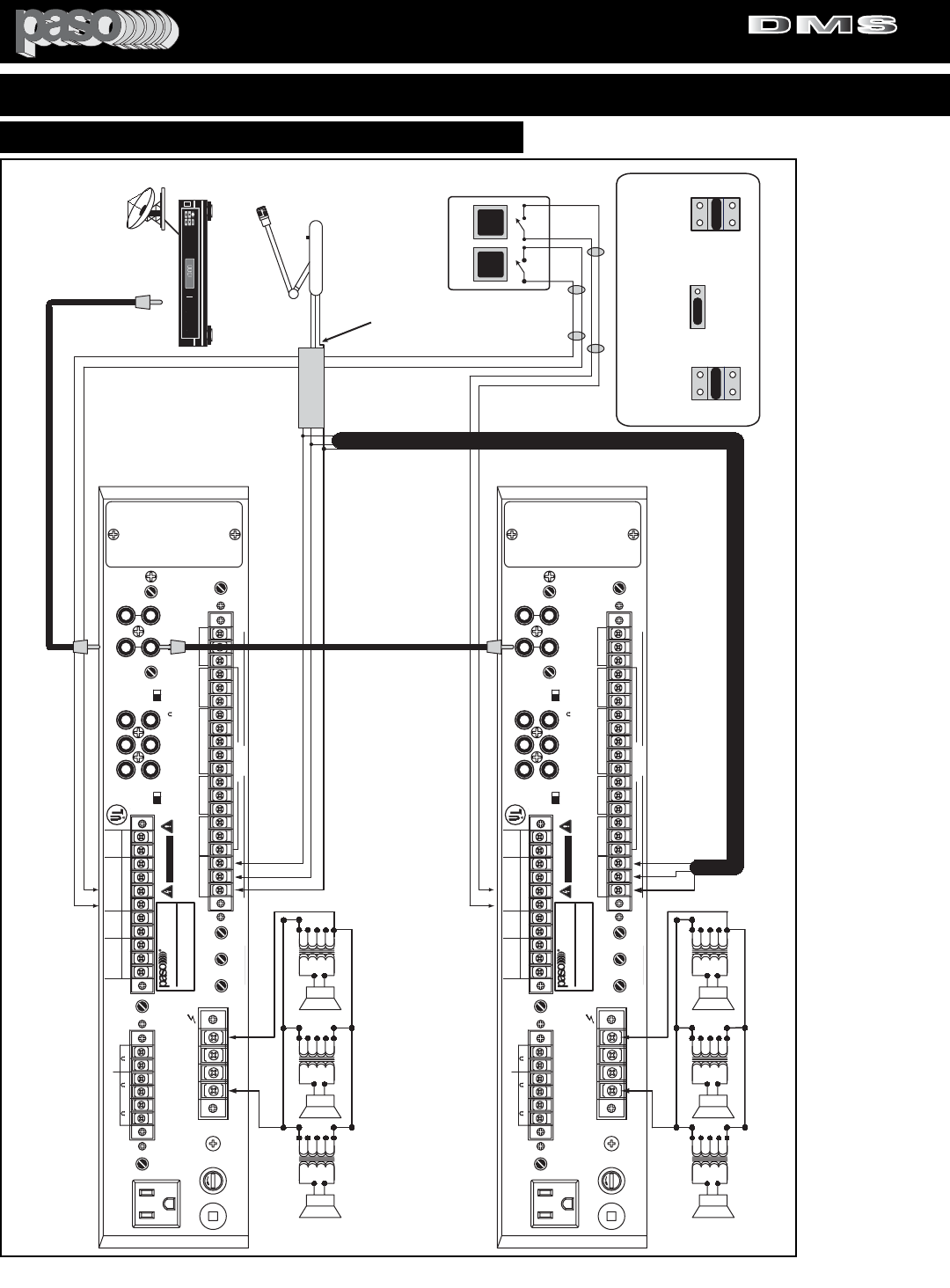
OPERATION - A 2 - Zone Paging Wiring Diagram Application is provided. The Paging Microphone is connected in parallel to all the Microphone Inputs. Two
Independent SPST Switches are provided for the Paging Zone Selection. MUSIC - The MUSIC SOURCE (Satellite Receiver) is cascade connected to the
two Amplifiers. ZONE PAGING - When one or more Zone Switches are activated the UNMUTE Function OPENS the Microphone Channel on the Amplifier
selected and the MICROPHONE is active for the PAGING. Simultaneously the MUSIC is MUTED ONLY ON THE ZONE (OR ZONES) SELECTED.
Independent MUSIC SOURCE may be provided to each of the Amplifiers if required. MOH - MUSIC ON HOLD is available from each of the Amplifiers used.
The MOH source maybe selected from either the AUX 1, AUX 2 or the MODULE Input and is immune to Paging or the MUTE/UNMUTE Function.
2 ZONE PAGING AND MUSIC WIRING DIAGRAM
21
ZONE 1
2 ZONE PAGING
SELECTORS
ZONE 2
HOT
COMMON
GROUND (SHIELD)
MUSIC SOURCE LINE
PAGING MICROPHONE
MICROPHONE WIRE
2 Conductor Shielded
Paging Microphone can be
Unswitched and always ON
MUSIC OUTPUT
SATELLITE RECEIVER
SER. NO.
ATTENTION:
AFIN DE REDUIRE LE RISQUE
D'INCENDIE REMPLACER SEUL PAR UN
FUSIBLE DE MEME TYPE.
COM 8 25V 70V
SPEAKER OUTPUT
GROUND
LINE FUSE
5A 250V
117V 500W MAX
117V 60HZ
R
L
LEVEL LEVEL
EQ LINK
ATTENUATOR ATTENUATOR
VOX-1
UNSWITCHED
0 600
ZONE 2
ZONE 1 24V DC
250 mA
0 8 0 8
VOX-2 MUTE-2
SENS
SENS DELAY
IN OUT
TEL
G COM HOT
NC C NO
+-
MIC1 G M2 M1 RVC
VOX RELAY
GROUND
UNMUTE
MUTE 1
MUTE 2
47kohm 100mV
(AUX1) (AUX2)
ZONE 2
ZONE 1
INPUT-4(AUX1)
BALANCED
250ohm 1.5mV
47kohm 100mV
INPUT-5(AUX2)
ON OFF
POWER RATING
SUPPLY VOLTAGE
POWER CONSUMPTION
120 W RMS
117V 60 HZ
850 VA
DMS3120
LISTED
COMMERCIAL
AUDIO
EQUIPMENT
30TJ
CUS
MIX
BUSS
LINE OUT
600
PRE
OUT
POWER
IN
SUB OUT
PRE EQ
SUB OUT
POST EQ TONE
BYPASS
CAUTION: TO REDUCE THE RISK OF FIRE OR
SHOCK DO NOT EXPOSE THIS APPLIANCE TO
RAIN OR MOISTURE. DO NOT REMOVE COVER.
THERE ARE NO USER SERVICEABLE PARTS
INSIDE. REFER SERVICING TO QUALIFIED
SERVICE PERSONNEL.
DIGITAL MUSIC AMPLIFIER
CAUTION: TO REDUCE THE
RISK OF FIRE, REPLACE
ONLY WITH SAME TYPE
FUSE.
MOH OUT
BALANCED
MASTER
REMOTE
VOLUME
EQ LINK
CAUTION
RISK OF ELECTRIC SHOCK
DO NOT OPEN
WARNING: THIS APPLIANCE
MUST BE EARTHED
ATTENTION: POUR REDUIRLES RISQUES D' INCENDIE
OU DE CHOC ELECTRIQUE, NE PAS EXPOSER A LA PLUIE
OU L' HUMIDITE, NE PAS ENLEVER LE COUVERCLE. AUCUN
REGLAGE A L' INTERIEUR. POUR REPARATION CONSULTER
UNE PERSONNE QUALIFIEE
INPUT 4 (MIC) INPUT 3 (MIC)
INPUT 2 (MIC)
INPUT 1 (MIC)
G COM HOT RVC RVC G COM HOT G COM HOT G COM HOT G COM HOT
INPUT 4
REMOTE
VOLUME
RVC
PROFESSIONAL AUDIO & SOUND
1 WATT 1 WATT
AUX2
47Kohm 100 mV
INPUT5 (MIC-AUX2)
600 ohm 100mV
CAUTION: REMOVE
POWER CORD FROM
AC OUTLET PRIOR TO
INSTALLING MODULE
PORT ACCEPTS
STANDARD
MODULE
INPUT 5
MIC-AUX 2
BY INTERNAL
SWITCH
TEL OUTPUT
LEVEL
25V/70V Speaker 25V/70V Speaker 25V/70V Speaker
25V/70V Speaker 25V/70V Speaker 25V/70V Speaker
ZONE 1
ZONE 2
MUSIC SOURCE LINE
UNMUTE
GROUND
UNMUTE
GROUND
3120 2 Zone Diagram
OFF
SW215
JUMPER
VOX 1 ON
INPUT 1
MIC 1
V1
V2
SW205
OFF
JUMPER
On
MIC 1
UNMUTE
OFF
MUTE 1 ON
SW217
JUMPER
INPUT 4
AUX 1
M1
M2
JUMPERS SETTING
ON AMPLIFIERS 1 & 2
SPST
SWITCHES
Fig. 19 - 2 Zone Paging and Music System
PROFESSIONAL AUDIO & SOUND
®
TM
DIGITAL MUSIC SERIES
DIGITAL MUSIC AMPLIFIERS
PAGE 20 SPECIFICATIONS ARE SUBJECT TO CHANGE WITHOUT NOTICE DMS3040/3080/3120
INSTALLATION AND WIRING
CONNECTING TO AN EXTERNAL EQUALIZER
The Amplifier is equipped with an External Equalizer Link
to allows the use of an External Equalizer for applications
requiring
Frequency Selective Acoustic Correction
. The
Amplifier is furnished with the two jacks of the Link bridged
by a SELECTOR SWITCH. When the EQ LINK Switch
(REFERENCE 12) is the IN position the internal
Preamplifier to Amplifier Link (Reference 13) is broken
allowing the insertion of an External Equalizer.
INSTALLATION TIPS
1) Use high quality, short length audio cables and position
the Equalizer in close proximity to the Amplifier. Avoid
mounting the EQ on top of the Amplifier unless is Rack
mounted.
2) Be sure that the Amplifier input controls and the EQ level
control are set at zero prior to turning the system On.
3) The Amplifier TONE BY PASS SWITCH (Reference 17)
should be set to ON ( linear response position).
4) Carefully adjust the EQ Level Control to avoid distortion
caused by excessive signal boost.
5) Follow the instructions supplied with the Equalizer.
WIRING
To connect to an External Equalizer use two (2) single con-
ductor shielded audio cables terminated in a single prong
phono plug on both ends.
3120 EQlink
EXTERNAL EQUALIZER
paso
To Input of Equalizer
To Output of Equalizer
12
13
EQ LINK
IN OUT
PRE
OUT
POWER
IN
EQ LINK
17
ON OFF
TONE
BYPASS
SET EQ LINK SWITCH TO IN
EXTERNAL EQUALIZER LINK
Fig. 20 - Rear Panel External Equalizer Link Diagram
3120 Mixbuss
15
ON
MIX
BUSS
LINE OUT
600
15
ON
MIX
BUSS
LINE OUT
600
AMPLIFIER A AMPLIFIER B
MIX BUSS BRIDGING
Fig. 20B - Rear Panel Mix Buss Bridging Diagram
BRIDGING TWO AMPLIFIERS
The MIX BUSS (Reference 15)
allows two Amplifiers to be bridged
and share all inputs.
All signal sources connected to all
the inputs are common to the output
of both amplifiers. Muting and level
controls operate in exactly the same
way as if only one amplifier was
used.
MIX BUSS BRIDGING
WIRING
CABLE
To bridge two amplifiers or to con-
nect to an external Mixer use a sin-
gle conductor shielded audio cable
terminated in a single prong phono
plug on both ends.
SET TONE BY PASS SWITCH TO ON
PROFESSIONAL AUDIO & SOUND
®
TM
DIGITAL MUSIC SERIES
DIGITAL MUSIC AMPLIFIERS
PAGE 21
SPECIFICATIONS ARE SUBJECT TO CHANGE WITHOUT NOTICEDMS3040/3080/3120
INSTALLATION AND WIRING
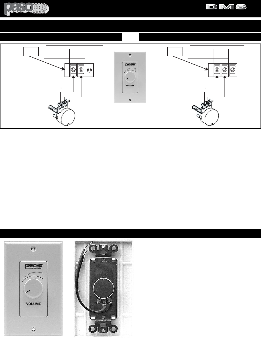
MASTER REMOTE VOLUME
MASTER
REMOTE VOLUME
CONTROL 10 K ohm
POTENTIOMETER
3120 Remote Volume
11
RVC
MASTER
REMOTE
VOLUME
RVC
Paso Remote
Volume Control
RVC10W
INPUT 4 (AUX 1)
REMOTE VOLUME
CONTROL 10 K ohm
POTENTIOMETER
26
RVC
INPUT 4
REMOTE
VOLUME
RVC
Fig. 21 - Master Remote Volume Control Diagram
REMOTE VOLUME CONTROLS
The Amplifier features two independent Remote Volume Control Capability: The INPUT 4 (AUX 1) Remote Volume (Reference 26) and
the MASTER REMOTE VOLUME CONTROL (Reference 11). A 10 K ohm Potentiometer is required for either control. Mount the 10 K
Pot on a suitable Wall Plate or any other convenient surface and connect to the Amplifier RVC Terminals as shown in the Diagram. The
Paso Model RVC10W Decora Style Remote Volume Control may be used.
INPUT 4 (AUX 1) OPERATION
When connected the Remote Volume adjusts the INPUT 4 (AUX 1) Level only. Usually this input is utilized for the Music Source (Satellite
Receiver, CD Player, etc.).
MASTER VOLUME OPERATION
The Control is a Master Volume and controls all the Inputs of the Amplifier with the exception of the MOH and ZONE 1 and ZONE 2
Outputs.
CABLE
To connect the Remote Control to the Amplifier use a two conductor wire not less than AWG 24. While the Remote Volume System uses
DC rather than audio caution should be exercised in the layout of the wire. Always avoid routing next to power lines. If the total wire resist-
ance exceeds 3 K ohm the Volume may not go down to zero.
REMOTE VOLUME CONTROL - OPTIONAL ACCESSORY
MODEL RVC10W REMOTE VOLUME CONTROL
Remote Volume Control Potentiometer. Single
Gang Decora Style Plate.
SPECIFICATIONS
Control: 10 K ohm High Quality Control.
Connection: 6” Two Wire, color coded (Black and
Red) Pigtails stripped and tinned. Color Finish:
White. Dimensions: Front Plate = 4.5” High, 2.75”
Wide. Depth: 0.5”. Mounting Hardware: Supplied.
INPUT 4 (AUX 1) REMOTE VOLUME
Fig. 21B - Input 4 Remote Volume Control Diagram
Fig. 21C - RVC10W Front View Fig. 21D - RVC10W Rear View
PROFESSIONAL AUDIO & SOUND
®
TM
DIGITAL MUSIC SERIES
DIGITAL MUSIC AMPLIFIERS

PAGE 22 SPECIFICATIONS ARE SUBJECT TO CHANGE WITHOUT NOTICE DMS3040/3080/3120
INSTALLATION AND WIRING
MODULE TYPE
The Amplifier accepts Audio Modules having a 6 Contact PCB Derivation. Module mounting panel should be 3” H., 1-3/8”
W. (
78 X 35 mm
).
INSTALLATION
CAUTION: REMOVE POWER CORD FROM AC OUTLET PRIOR TO INSTALLING A MODULE. BE SURE THAT THE
MODULE OUTPUT LEVEL CONTROL IS SET AT “0” PRIOR TO THE INSTALLATION.
1) Locate Rear Panel Module Port (Reference 22) and unscrew the two crosshead screws holding the cover and set aside.
2) Reach inside the Amplifier and gently pull-out the Module Blue Ribbon Connector. If the Connector is tied to the chas-
sis remove the Amplifier Top Cover and with a cutter cut the Nylon Tie holding the connector.
NOTE: BE CAREFUL NOT TO CUT THE CONNECTOR WIRE HARNESS.
3) Pull-out the blue-ribbon connector through the port opening (do not pull-out wire harness excessively).
4) By keeping the connector gold contacts on the left insert the Module PCB contacts into the socket.
5) Push Module through port opening and secure to rear panel by using the two screws removed with the Module cover.
MODULE INSTALLATION
INSTALLING A MODULE
Fig. 22 - Rear Panel Module Installation Diagram
R
L
EQ LINK
ATTENUATOR ATTENUATOR
IN OUT
TEL
G COM HOT
47kohm 100mV
(AUX1) (AUX2)
INPUT-4(AUX1)
BALANCED
250ohm 1.5mV
47kohm 100mV
INPUT-5(AUX2)
ON OFF
LISTED
COMMERCIAL
AUDIO
EQUIPMENT
30TJ
CUS
MIX
BUSS
LINE OUT
600
PRE
OUT
POWER
IN
SUB OUT
PRE EQ
SUB OUT
POST EQ TONE
BYPASS
EQ LINK
WARNING: THIS APPLIANCE
MUST BE EARTHED
INPUT 4 (MIC) INPUT 3 (MIC)
INPUT 2 (MIC)
G COM HOT RVC RVC G COM HOT G COM HOT G COM HOT
INPUT 4
REMOTE
VOLUME
RVC
AUX2
47Kohm 100 mV
INPUT5 (MIC-AUX2)
600 ohm 100mV
INPUT 5
MIC-AUX 2
BY INTERNAL
SWITCH
TEL OUTPUT
LEVEL
Printed Board
Copper Side
Module Gold
Contacts
Module Bottom
Insert into Module Connector
Connector
Top
Gold
Contact
Front
View
Side
View
Cable from
Amplifier
3120 Module Install
CAUTION: REMOVE
POWER CORD FROM
AC OUTLET PRIOR TO
INSTALLING MODULE
PORT ACCEPTS
STANDARD
MODULE
22
PROFESSIONAL AUDIO & SOUND
®
TM
DIGITAL MUSIC SERIES
DIGITAL MUSIC AMPLIFIERS
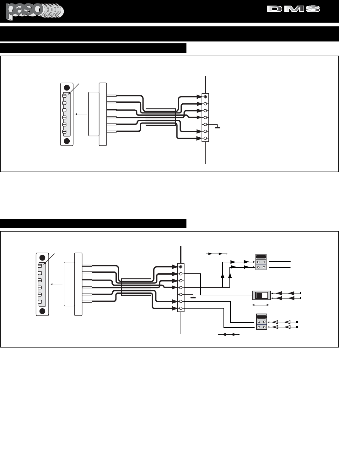
PAGE 23
SPECIFICATIONS ARE SUBJECT TO CHANGE WITHOUT NOTICEDMS3040/3080/3120
INSTALLATION AND WIRING
MODULE CONNECTOR DIAGRAM
Connector
Top Gold
Contact
Front
View Side
View
Cable from
Amplifier
3120 Module Schem
6
5
4
3
2
3
6
5
4
3
2
1
6
5
4
3
2
1
TO
MODULE
PCB
CONNECTOR
CN201
1
MODULE CONNECTOR
Connector Contacts
6 = + 24V DC
5 = Module Input
4 = Module Output
3 = Ground
2 = Mute Buss 1
1 = Mute Buss 2
Fig. 23 - Module Connector Contacts Diagram
MODULE CONNECTOR DIAGRAM - The above Diagram indicates the function of each of the six contacts of the Module
Connector. The Module Blue Ribbon Connector is attached to a wire harness and left floating beyond the Module Port
Cover. The Wire Harness Amplifier End is attached to Connector No. CN201 and plugged into the mating connector on the
Main Printed Circuit Board.
MODULE DEFAULT SETTINGS
Connector
Top Gold
Contact
Front
View Side
View
Cable from
Amplifier
3120 Module Functions
6
5
4
3
2
3
6
5
4
3
2
1
6
5
4
3
2
1
TO
MODULE
PCB
CONNECTOR
CN201
1
MODULE CONNECTOR
Connector Contacts
6 = + 24V DC
5 = Module Input
4 = Module Output
3 = Ground
2 = Mute Buss 1
1 = Mute Buss 2
V1
V2
OFF
VOX 2 BUSS OFF
X
VOX SEND
SW221
VOX 1 BUSS OFF
X
JUMPER
M2
M1OFF
MUTE 2 BUSS OFF
X
X
MUTE 1 BUSS OFF
MUTE RECEIVE
JUMPER
MODULE VOX - MUTE
JUMPERS AND INPUT SOURCE
SWITCH DEFAULT SETTING
SW222
MODULE INPUT
AUX 2 SOURCE
AUX 1 SOURCE
SW209
AUX 1 AUX 2
AUX 1 - AUX 2 SWITCH
MODULE OUTPUT
Fig. 23A - Module VOX - MUTE - INPUT SOURCE Default Settings
MODULE FUNCTIONS - The Module Port accepts a stan-
dard audio Module. When a Module is utilized several func-
tions can be activated by the Jumpers and Switch provided
for this Input.
VOX SEND - The SW221 Jumpers Set activates the VOX 1
- VOX 2 SEND or both. When a Signal is present at the
Module Output (Contact 4) then the VOX BUSS selected will
be active.
MUTE RECEIVE - The SW222 Jumpers Set activates the
MUTE 1 - MUTE 2 RECEIVE or both.When a Signal is pres-
ent at the MUTE BUSS 1 or MUTE BUSS 2 the MODULE
will be MUTED accordingly.
INPUT SOURCE - The SW209 Switch selectes the Input
Source for the Module either AUX 1 or AUX 2. The Signal
present at either Input will be sent to the MODULE INPUT
(Contact 5).
By selecting the proper Setting several functions can be
derived from the Module.
PROFESSIONAL AUDIO & SOUND
®
TM
DIGITAL MUSIC SERIES
DIGITAL MUSIC AMPLIFIERS
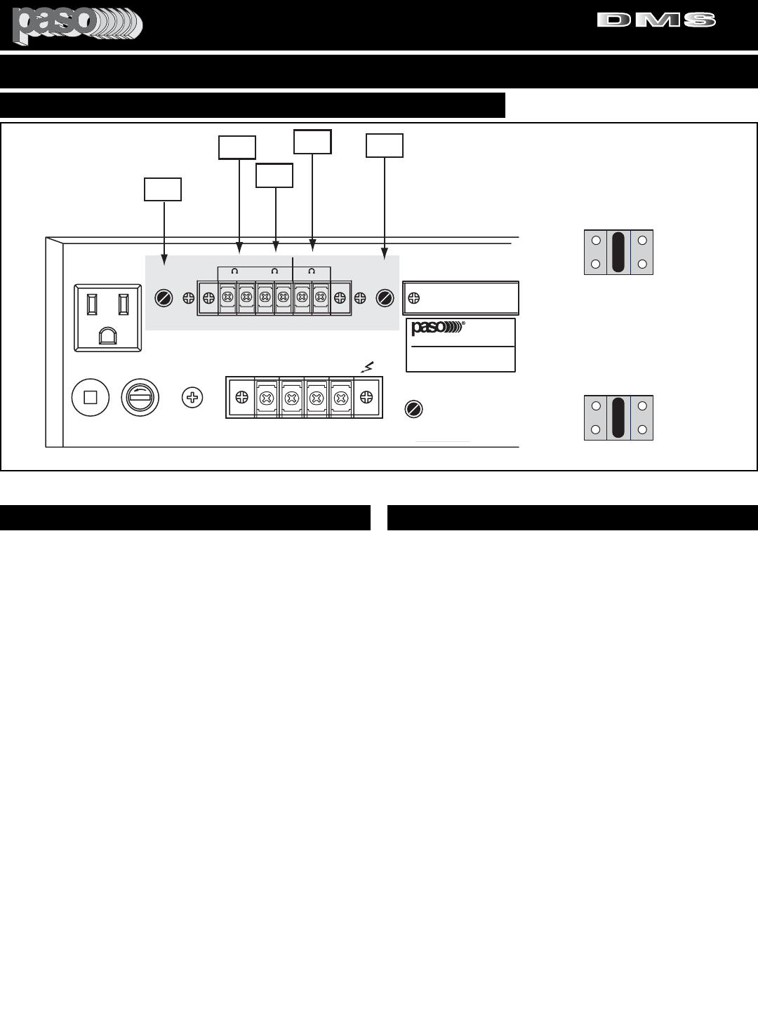
PAGE 24 SPECIFICATIONS ARE SUBJECT TO CHANGE WITHOUT NOTICE DMS3040/3080/3120
INSTALLATION AND WIRING
DMS3120 MOH 01
2
3
4
5
6
SER. NO.
CLASS 2 WIRING ACCEPTABLE
COM 8 25V 70V
SPEAKER OUTPUT
GROUND
LINE FUSE
5A 250V
117V 500W MAX
117V 60HZ
LEVEL LEVEL
VOX-1
UNSWITCHED
0 600
ZONE 2
ZONE 1
0 8 0 8
SENS
ZONE 2
ZONE 1
POWER RATING
SUPPLY VOLTAGE
POWER CONSUMPTION
CAUTION: TO REDUCE THE RISK OF FIRE OR
SHOCK DO NOT EXPOSE THIS APPLIANCE TO
RAIN OR MOISTURE. DO NOT REMOVE COVER.
THERE ARE NO USER SERVICEABLE PARTS
INSIDE. REFER SERVICING TO QUALIFIED
SERVICE PERSONNEL.
DIGITAL MUSIC AMPLIFIER
CAUTION: TO REDUCE THE
RISK OF FIRE, REPLACE
ONLY WITH SAME TYPE
FUSE.
MOH OUT
BALANCED
PROFESSIONAL AUDIO & SOUND
1 WATT 1 WATT
MODULE
JUMPER
SW702
AUX 1
AUX 2
MOH - ZONE 1 INPUT SOURCE
DEFAULT JUMPER SETTING
MODULE
JUMPER
SW701
AUX 1
AUX 2
ZONE 2 INPUT SOURCE
DEFAULT JUMPER SETTING
Fig. 24 - Rear Panel View - ZONE 1 - ZONE 2 - MOH Outputs - Source Selectors and Controls
ZONE 1 MOH AND 8 OHM OUTPUTS MOH - ZONE1 & 2 AMPLIFIER FUNCTIONS
MOH AMPLIFIER
a) The MOH Amplifier can receive programs from AUX
1 - AUX 2 and the MODULE.
b) Selection of the input source is by Internal Jumper.
c) The ZONE 1 independent 600 Ohm and 8 Ohm
Outputs may be used simultaneously.
d) The MOH 600 ohm Output is Transformer Balanced.
e) The Rear Panel ZONE 1 Level Control operates both
the 600 Ohm and 8 Ohm Outputs simultaneously.
MOH AND ZONE 1-2 OPERATION ISSUES
1) Paging from the Microphone Inputs or the Telephone
Input does not effect the MOH/ZONE 1-2 Amplifier.
2) Position of the INPUTS Level Control does not affect the
MOH/ZONE 1-2 Amplifier Output Level.
3) Position of the AUX 1 and AUX 2 ATTENUATOR does not
affect the MOH/ZONE 1-2 Amplifier Output Level.
4) Muting activation of M1 or M2 Buss (from Microphones or
Telephone) does not effect the Output of the MOH/ZONE 1-
2 Amplifier except if the INPUT SOURCE is set to MODULE
and the Module Output is Muted. See Module Settings.
ZONE 1 OUTPUTS
The DMS Amplifier is equipped with two 1 Watt, 8 ohm Amplifiers
and a separate 600 ohm MUSIC ON HOLD AMPLIFIER.
600 Ohm MOH - The MOH Output provides a 600 ohm, 1 Volt
Transformer Balanced Output (Reference 3).
1 WATT, 8 Ohm - Simultaneously a Second Zone 8 ohm, 1 Watt
Output may be utilized to drive up to 4 Speakers (Reference 4).
OUTPUT LEVEL CONTROL - A Level Control for both the 600
ohm Output and the 1 Watt Output is provided (Reference 2)
MOH AND 8 Ohm AMPLIFIER INPUT SOURCE SELECTION
The program source for the Input of the 600 ohm MOH Output and
the 8 ohm Output can be selected from either AUX 1 - AUX 2 or
the MODULE source. Set the Jumpers Set No. SW 702 to desired
position. Default setting is AUX 1.
ZONE 2 OUTPUT
1 WATT, 8 Ohm - A Second Zone 8 ohm, 1 Watt Output may be
utilized to drive up to 4 Speakers (Reference 5).
OUTPUT LEVEL CONTROL - A Level Control for the 1 Watt
Output is provided (Reference 6)
ZONE 2 - 8 Ohm AMPLIFIER INPUT SOURCE SELECTION
The program source for the Input the 8 ohm Output can be select-
ed from either AUX 1 - AUX 2 or the MODULE source. Set the
Jumpers Set No. SW 701 to desired position. Default setting is
AUX 1.
PROFESSIONAL AUDIO & SOUND
®
TM
DIGITAL MUSIC SERIES
DIGITAL MUSIC AMPLIFIERS
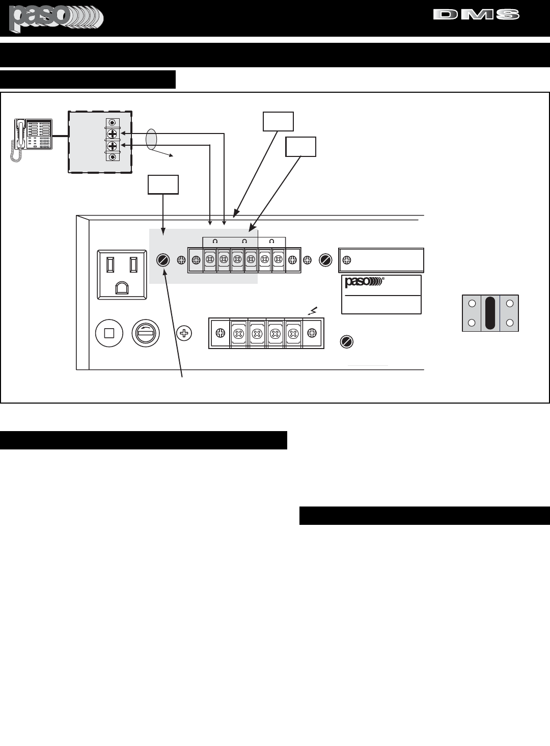
PAGE 25
SPECIFICATIONS ARE SUBJECT TO CHANGE WITHOUT NOTICEDMS3040/3080/3120
INSTALLATION AND WIRING
MOH CONNECTIONS
3120 MOH Zone 1
AWG 18 TWISTED PAIR
MOH
Input
600
Ohm
Telephone System
KSU
600 ohm MOH System
Telephone
MOH OTPUT LEVEL CONTROL
2
3
4
SER. NO.
CLASS 2 WIRING ACCEPTABLE
COM 8 25V 70V
SPEAKER OUTPUT
GROUND
LINE FUSE
5A 250V
117V 500W MAX
117V 60HZ
LEVEL LEVEL
VOX-1
UNSWITCHED
0 600
ZONE 2
ZONE 1
0 8 0 8
SENS
ZONE 2
ZONE 1
POWER RATING
SUPPLY VOLTAGE
POWER CONSUMPTION
DIGITAL MUSIC AMPLIFIER
CAUTION: TO REDUCE THE
RISK OF FIRE, REPLACE
ONLY WITH SAME TYPE
FUSE.
MOH OUT
BALANCED
PROFESSIONAL AUDIO & SOUND
1 WATT 1 WATT
MODULE
JUMPER
SW702
AUX 1
AUX 2
MOH - ZONE 1
INPUT SOURCE
DEFAULT JUMPER
SETTING
Fig. 25 - Rear Panel MOH Connection Diagram
MOH/ZONE 1 AMPLIFIER SOURCE SELECTOR
MOH AMPLIFIER
An independent 600 ohm, 1 Volt Output, Transformer Balanced
MUSIC-ON-HOLD Amplifier is provided. The Input SOURCE of the
MOH Amplifier can be selected from either the AUX 1 - AUX 2 or MOD-
ULE.
MOH - 600 OHM SYSTEM
Most Phone systems operate on a 600 ohm Input Impedance, if the
Impedance required is 600 ohm connect the Amplifier to the Phone
System MOH by using the diagram above (Reference 3).
MOH - 8 OHM, 1 WATT SYSTEM
Some older Key Phone systems require a 1 watt Power Output having
an Output Impedance of 8 ohm to drive the Music on Hold feature. If
the Impedance required is 8 ohm connect the Phone system MOH to
the 8 ohm, 1 Watt MOH Output of the Amplifier (Reference 4).
CABLE
Use a cable consisting of a twisted pair of at least AWG 18. Use care
in extending the cable and avoid routing near power lines, fluorescent
lights and other systems that may generate a disturbing electric field.
SOURCE SELECTOR
Select the Input Source desired by following the instructions at right.
CAUTION: REMOVAL OF THE COVER PRESENTS AN ELECTRI-
CAL SHOCK HAZARD !
MUSIC ON HOLD AMPLIFIER
MOH/ZONE 1 SOURCE SELECTOR
The Source for the MOH/ZONE 1 Amplifier can be selected
from either the AUX 1 - AUX 2 or MODULE by setting the
JUMPER SET No. SW702 provided for this purpose. Default
Setting for this Jumper Set is AUX 1. To change the setting do
the following:
ACCESS TO THE MOH/ZONE 1 INPUT SOURCE SETTING
1) Remove Power Cord from AC Outlet.
2) Remove the three screws on each side of the amplifier
holding the amplifier cover.
3) Lift Cover and locate the Jumpers Set No SW702 on the
MOH Amplifier Board (see Function Switches Jumpers
Location Diagram).
4) Set Jumper as required (AUX 1 - AUX 2 or MODULE)
5) Replace protective cover.
LEVEL CONTROL
After the wiring is completed adjust the MOH/ZONE 1
Amplifier Level Control on the rear panel to the desired output
level (Reference 2).
PROFESSIONAL AUDIO & SOUND
®
TM
DIGITAL MUSIC SERIES
DIGITAL MUSIC AMPLIFIERS
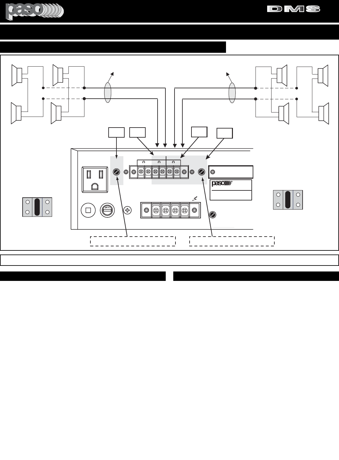
PAGE 26 SPECIFICATIONS ARE SUBJECT TO CHANGE WITHOUT NOTICE DMS3040/3080/3120
INSTALLATION AND WIRING
USING SPEAKERS FOR ZONE 1 - ZONE 2
3120 Zone 1&2
24
5
SER. NO.
CLASS 2 WIRING ACCEPTABLE
COM 8 25V 70V
SPEAKER OUTPUT
GROUND
LINE FUSE
5A 250V
117V 500W MAX
117V 60HZ
LEVEL LEVEL
VOX-1
UNSWITCHED
0 600
ZONE 2
ZONE 1
0 8 0 8
SENS
ZONE 2
ZONE 1
POWER RATING
SUPPLY VOLTAGE
POWER CONSUMPTION
DIGITAL MUSIC AMPLIFIER
CAUTION: TO REDUCE THE
RISK OF FIRE, REPLACE
ONLY WITH SAME TYPE
FUSE.
MOH OUT
BALANCED
PROFESSIONAL AUDIO & SOUND
1 WATT 1 WATT
MODULE
JUMPER
SW701
AUX 1
AUX 2
ZONE 2
INPUT SOURCE
DEFAULT JUMPER
SETTING
ZONE 1 OUTPUT LEVEL CONTROL
AWG 18
TWISTED PAIR
Up to Four 8 ohm Speakers may
be Connected
1/4W
1/4W
1/4W
1/4W
8
OHM ZONE 1
AWG 18
TWISTED PAIR
4 Speaker System Max. Power Output= 1/4W Each 1/4W
1/4W
1/4W
1/4W
8
OHM
8
OHM 8
OHM
8
OHM
8
OHM
8
OHM 8
OHM
Up to Four 8 ohm Speakers may
be Connected
ZONE 2
ZONE 2 OUTPUT LEVEL CONTROL
MODULE
JUMPER
SW702
AUX 1
AUX 2
MOH - ZONE 1
INPUT SOURCE
DEFAULT JUMPER
SETTING
6
Fig. 26 - Rear Panel Zone 1 and 2 Speaker Connection Diagram
ZONE 1 AND 2 OPERATION
The Amplifier is equipped with two independent 1 Watt, 8
ohm Outputs designated ZONE 1 (Reference 4) and ZONE
2 (Reference 5). The Outputs may be utilized to power up to
4 speakers in various combinations as described in the dia-
grams on the next page. This feature will provide a SEC-
OND and THIRD ZONE (in addition to the main output) with
up to 1 Watt of output power and will amplify only the
Source from either AUX 1 - AUX 2 or MODULE (see input
source selection) and will not be affected by the Paging
(from MIC or TEL), VOX or MUTING.
It can be used in any area (up to 1 Watt) where only a
Program Source is desired uninterrupted by Paging.
CABLE
Use an AWG 18 jacketed, twisted pair cable.
ZONE 1 AND 2 OPERATION ZONE 1 AND 2 SETTINGS
INPUT SOURCE SELECTOR
Independent JUMPER SETS for ZONE 1 (SW702) and
ZONE 2 (SW701) are available to select the Input Source
for the two 1 Watt Amplifiers.
DUAL PROGRAM SOURCE CAPABILITY
If desired separate program Sources may be used for
ZONE 1 and ZONE 2.
EXAMPLE: Use the program source from AUX 1 for ZONE
2 and the program source from AUX 2 for ZONE 2.
Select the Input Source desired by following the instructions
in the MOH Amplifier Source Selection section.
LEVEL CONTROL
After the wiring is completed adjust the ZONE 1 (
Reference
2) and ZONE 2 (
Reference
6) Level Controls on the rear
panel to the desired output level.
PROFESSIONAL AUDIO & SOUND
®
TM
DIGITAL MUSIC SERIES
DIGITAL MUSIC AMPLIFIERS
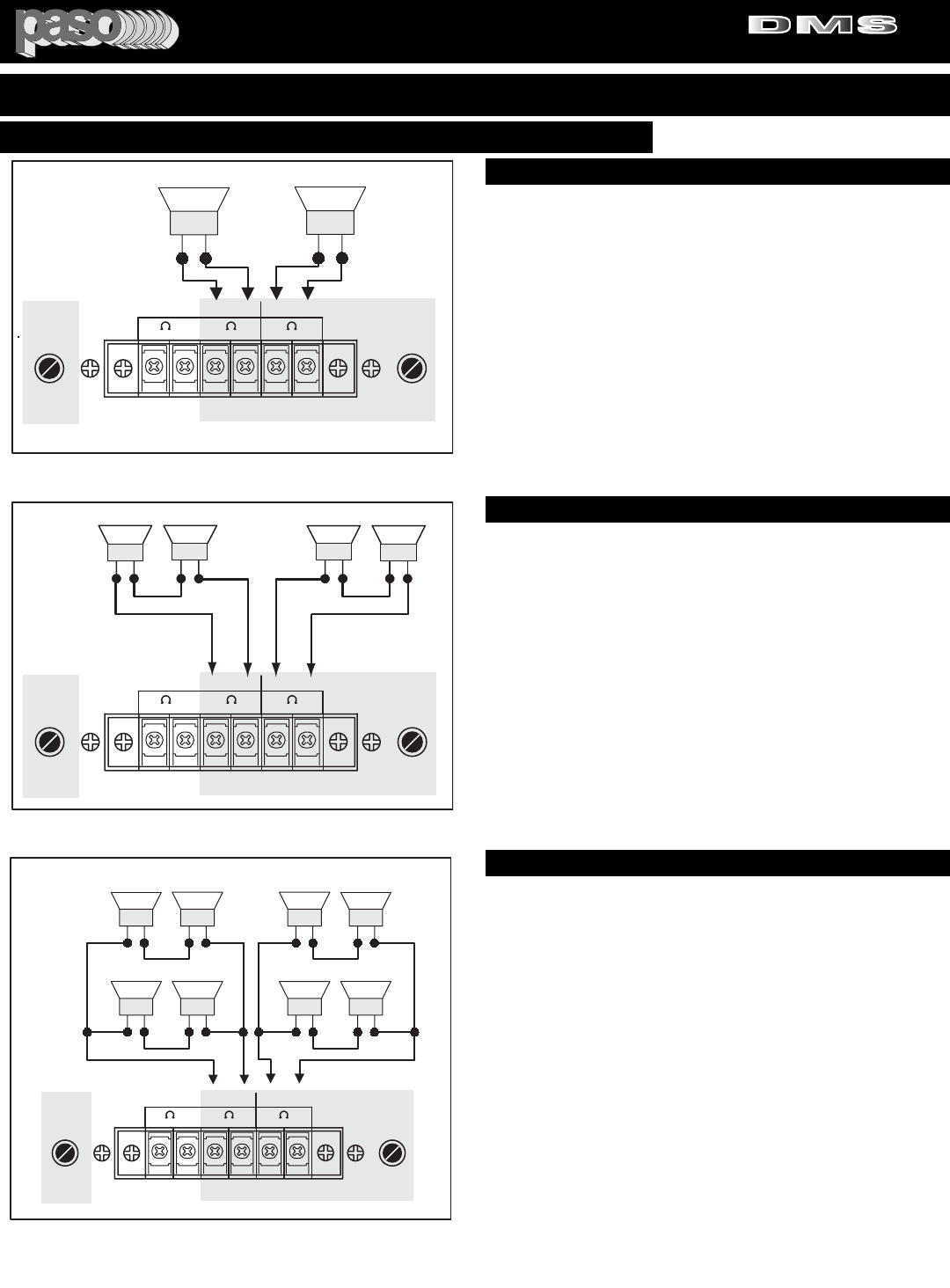
PAGE 27
SPECIFICATIONS ARE SUBJECT TO CHANGE WITHOUT NOTICEDMS3040/3080/3120
INSTALLATION AND WIRING
LEVEL LEVEL
0 600
ZONE 2
ZONE 1
0 8 0 8
ZONE 2
ZONE 1
MOH OUT
BALANCED 1 WATT 1 WATT
3120 MOHspk01
Max. Power Output
1 Watt
+
-
+
-
8 Ohm 8 Ohm
Zone 1 Zone 2
LEVEL LEVEL
0 600
ZONE 2
ZONE 1
0 8 0 8
ZONE 2
ZONE 1
MOH OUT
BALANCED 1 WATT 1 WATT
-
8 Ohm
Zone 1 Zone 2
+
+
¼ W ¼ W
3120 Mohspk02
8 Ohm
+
+
-
--
4 ohm 4 ohm
½ W ½ W
When using two
4 Ohm Speakers
the maximum
Output Power to
each Speaker is
½ Watt
When using two 8 Ohm
Speakers the maximum
Output Power to each
Speaker is ¼ Watt
Fig 27 - Using one 8 ohm Speaker
Zone 1
3120 Mohspk03
¼ W
Maximum Output
Power to each
Speaker is
¼ Watt
+
+
--
+
+
--
8 ohm8 ohm
8 ohm8 ohm
+
+
--
+
+
--
8 ohm8 ohm
8 ohm8 ohm
Zone 2
¼ W
¼ W ¼ W
¼ W ¼ W
¼ W ¼ W
LEVEL LEVEL
0 600
ZONE 2
ZONE 1
0 8 0 8
ZONE 2
ZONE 1
MOH OUT
BALANCED 1 WATT 1 WATT
Fig 27A - Using two 4 or 8 ohm Speakers
Fig 27B - Using four 8 ohm Speakers
USING A SINGLE 8 OHM SPEAKER WIRING
USING A SINGLE 8 OHM SPEAKER PER ZONE
A single 8 ohm Speaker may be used connected to the
ZONE 1 and ZONE 2 1 Watt Output. In this configuration up
to 1 Watt of Power will be available on each Speaker.
Independent Level Controls are provided.
ZONE 1 - ZONE 2 CONNECTING SPEAKERS
USING TWO 4 OR 8 OHM SPEAKERS WIRING
USING TWO 4 OR 8 OHM SPEAKERS
The Figure at left shows:
ZONE 1 with two 4 ohm speakers connected in series, each
speaker provides ½ Watt power output (1 Watt Total).
ZONE 2 with two 8 ohm speakers connected in series, each
speaker provides ¼ Watt power output (½ Watt Total).
Independent Level Controls are provided.
USING FOUR 8 OHM SPEAKERS WIRING
USING FOUR 8 OHM SPEAKERS PER ZONE
Four 8 ohm Speakers are used and connected to the 1 Watt
Output. In this configuration up to 1/4 Watt of Power will be
available on each Speaker (1 Watt Total).
Independent Level Controls are provided.
PROFESSIONAL AUDIO & SOUND
®
TM
DIGITAL MUSIC SERIES
DIGITAL MUSIC AMPLIFIERS
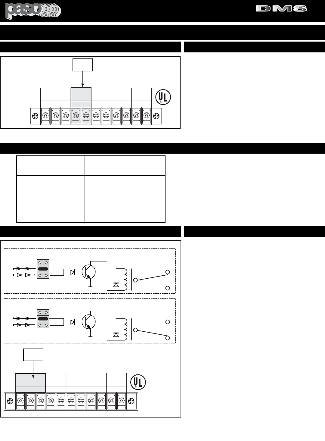
PAGE 28 SPECIFICATIONS ARE SUBJECT TO CHANGE WITHOUT NOTICE DMS3040/3080/3120
POWER SUPPLY
The Amplifier provides a 24 Volt - 250 mA DC Regulated
Auxiliary Power Supply Output (Reference 8).
CABLE
To connect the Power Supply Output to accessories use a
two conductor wire not less than AWG 18. This minimum
wire gauge is necessary to minimize potential Voltage
Drops in long wire connection applications. For wire resist-
ance refer to Table below.
24 VOLT POWER SUPPLYREGULATED AUXILIARY POWER SUPPLY
8
24V DC
250 mA
NC C NO
+-
MIC1 G M2 M1 RVC
VOX RELAY
GROUND
UNMUTE
MUTE 1
MUTE 2
C
MASTER
REMOTE
VOLUME
RVC
3120 Power Supply Output
Fig. 28 - 24 Volt Power Supply Output Diagram
WIRE GAUGE - RESISTANCE TABLE
WIRE RESISTANCE IN
AWG OHMS per 1000 Ft.
16 4.016
18 6.385
20 10.15
22 16.14
24 25.67
26 40.81
NOTE:
When calculating the Wire Resistance for each run
using a two conductor Wire the wire Resistance
should be doubled.
EXAMPLE: The Total Resistance of a 1000 Ft. run
of a AWG 24 two conductor Wire is:
25.67 X 2= 51.34 Ohm
VOX RELAY
The Amplifier provides a VOX RELAY (Reference 7) with a
single pole dual throw set of contacts. Figure A at left
shows the contacts when the Relay is not activated. Figure
Bshows the contacts when the Relay is activated.
The Relay can be configured to activate when either VOX
1 (M1) or VOX 2 (M2) or both (VOX 1 and VOX 2) are acti-
vated.
The VOX RELAY will remain engaged for as long as the
VOX is active.
SWITCHSET SW206 - The SW206 is defaulted to M1.
When VOX 1 is activated the Relay is switched ON. The
factory setting can be changed to set the Relay to activate
with either VOX 1 - VOX 2 or both.
Both Jumpers (M1 - M2) may be installed.
RELAY CONTACTS RATING
7 AMPERE AT 30 VDC MAXIMUM RATING.
VOX RELAY FUNCTIONSVOX RELAY
7
24V DC
250 mA
NC C NO
+-
MIC1 G M2 M1 RVC
VOX RELAY
GROUND
UNMUTE
MUTE 1
MUTE 2
C
MASTER
REMOTE
VOLUME
RVC
3120 Vox relay 01
COM
NC
NO
RL201
VOX RELAY
Q237
D211
M2
M1
MUTE 2 BUSS OFF
X
MUTE 1 BUSS ON
JUMPER
SW206
+
COM
NC
NO
RL201
VOX RELAY
Q237
D211
M2
M1
MUTE 2 BUSS OFF
X
MUTE 1 BUSS ON
JUMPER
SW206
+
VOX NOT ACTIVATED
VOX ACTIVATED
SWITCHSET SW206 DEFAULT SETTING
A
B
Fig. 28A - VOX Relay Output Terminals
INSTALLATION AND WIRING
PROFESSIONAL AUDIO & SOUND
®
TM
DIGITAL MUSIC SERIES
DIGITAL MUSIC AMPLIFIERS
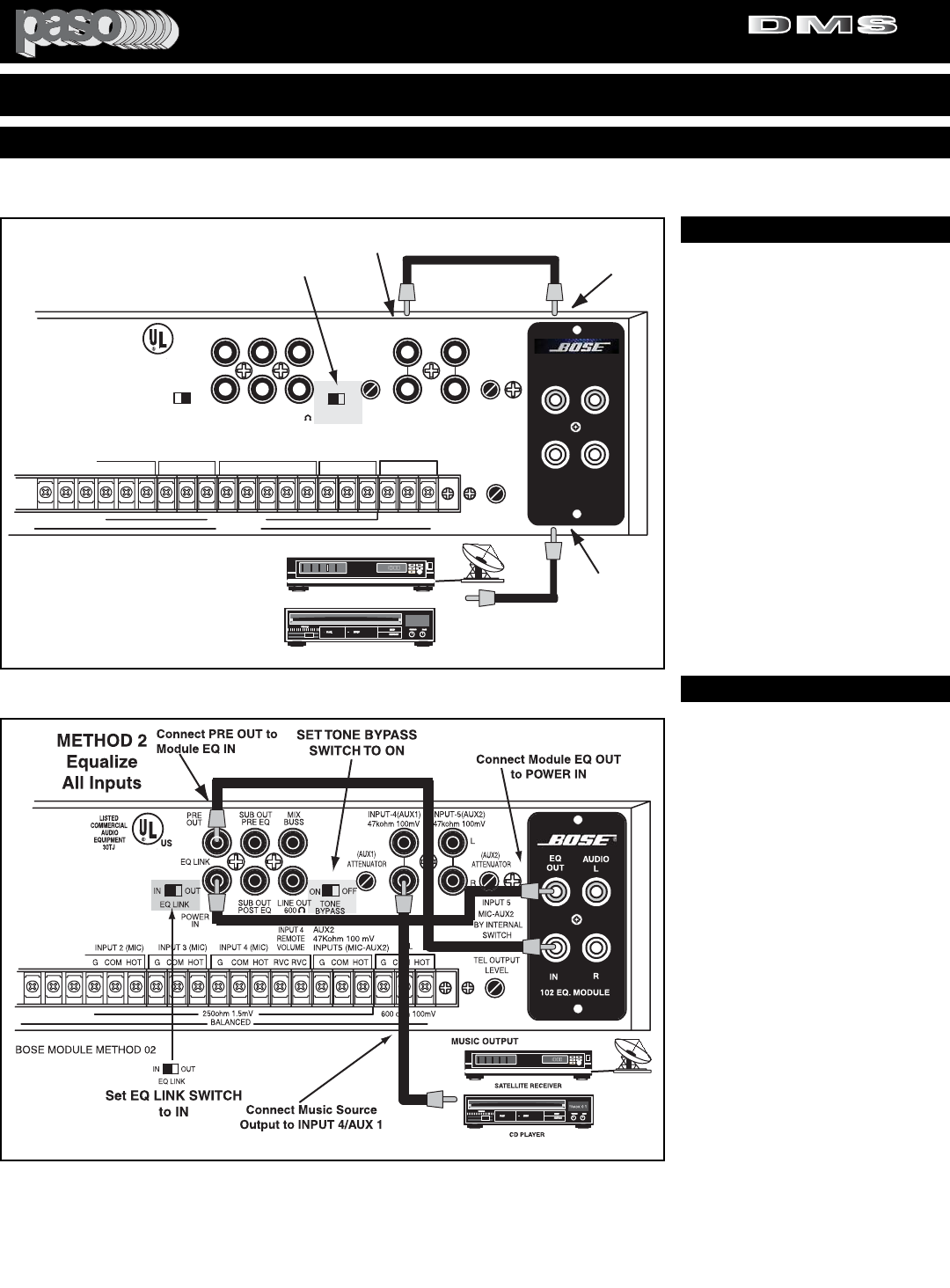
PAGE 29
SPECIFICATIONS ARE SUBJECT TO CHANGE WITHOUT NOTICEDMS3040/3080/3120
EQ
OUT AUDIO
L
IN R
102 EQ. MODULE
R
L
EQ LINK
ATTENUATOR ATTENUATOR
IN OUT
TEL
G COM HOT
47kohm 100mV
(AUX1) (AUX2)
LEVEL
TEL OUTPUT
INPUT-4(AUX1)
BALANCED
INPUT 5
MIC-AUX2
BY INTERNAL
SWITCH
250ohm 1.5mV
47kohm 100mV
INPUT-5(AUX2)
ON OFF
LISTED
COMMERCIAL
AUDIO
EQUIPMENT
30TJ
US
MIX
BUSS
LINE OUT
600
PRE
OUT
POWER
IN
SUB OUT
PRE EQ
SUB OUT
POST EQ TONE
BYPASS
EQ LINK
WARNING: THIS APPLIANCE
MUST BE EARTHED
INPUT 4 (MIC) INPUT 3 (MIC)
INPUT 2 (MIC)
G COM HOT RVC RVC G COM HOT G COM HOT G COM HOT
INPUT 4
REMOTE
VOLUME
AUX2
47Kohm 100 mV
INPUT5 (MIC-AUX2)
600 ohm 100mV
SATELLITE RECEIVER
CD PLAYER
MUSIC OUTPUT
Connect to INPUT 4/AUX 1 Connect to
Module
EQ OUT
Connect Music
Source Output
to Module EQ IN
METHOD 1
Equalize
Music Only
BOSE MODULE METHOD 01
SET TONE BYPASS
SWITCH TO ON
TRACK 01
INSTALLING AND USING A BOSE® EQUALIZER MODULE
Fig. 26 - Method 1 Module Wiring Diagram
BOSE® is a Registered Trademark of BOSE Corporation
METHOD 1
EQUALIZING THE PROGRAM ONLY
BY USING THIS METHOD THE
MUSIC PROGRAM ONLY IS EQUAL-
IZED BY THE MODULE.
BE SURE THAT THE TONE BYPASS
SWITCH IS IN THE ON POSITION
1) Connect the Output of the PRO-
GRAM SOURCE unit to the Module
IN Jack.
2) Connect the EQ. OUT Jack of the
Module to INPUT 4/AUX 1 of the
Amplifier.
LEVEL CONTROLS - Adjust INPUT
4/AUX 1 Front Panel Control to 1
o'clock. Turn Rear Panel ATTENUA-
TOR Control slowly clockwise until the
desired Output Level is achieved After
above adjustments are completed use
the INPUT 4/AUX 1 Front Panel
Control to increase or decrease the
Music Level as desired.
CAUTION: PRIOR TO INSTALLING THE BOSE® MODULE IN THE AMPLIFIER FOLLOW THE INSTRUCTIONS SUPPLIED WITH
THE MODULE AND THEN READ THE INSTRUCTIONS IN THIS MANUAL’S “INSTALLING A MODULE” SECTION
METHOD 2
USING THE EQ LINK
BY USING THIS METHOD ALL THE
AMPLIFIER INPUTS ARE EQUAL-
IZED BY THE MODULE.
BE SURE THAT THE TONE BYPASS
SWITCH IS IN THE ON POSITION
1) Connect the Output of the PRO-
GRAM SOURCE unit to the INPUT 4
(or INPUT 2) L and R Jacks.
2) Connect the EQ. OUT Jack of the
Module to the POWER IN Jack of the
Amplifier.
3) Connect the EQ. IN Jack of the
Module to the PREAMP. OUT Jack of
the Amplifier.
4) Set EQ LINK Switch on the
Amplifier to IN.
LEVEL CONTROLS - Adjust INPUT
4/AUX 1 Front Panel Control to 1
o'clock. Turn Rear Panel ATTENUA-
TOR Control slowly clockwise until the
desired Output Level is achieved After
above adjustments are completed use
the INPUT 4/AUX 1 Front Panel
Control to increase or decrease the
Music Level as desired.
Fig. 26B - Method 2 Module Wiring Diagram
INSTALLATION AND WIRING
PROFESSIONAL AUDIO & SOUND
®
TM
DIGITAL MUSIC SERIES
DIGITAL MUSIC AMPLIFIERS

PAGE 30 SPECIFICATIONS ARE SUBJECT TO CHANGE WITHOUT NOTICE DMS3040/3080/3120
RESTAURANT/DINER WITH MUSIC AND JUKEBOX - APP. DATA 121
PROFESSIONAL AUDIO & SOUND
®
TM
DIGITAL MUSIC SERIES
DIGITAL MUSIC AMPLIFIERS
SER. NO.
ATTENTION:
AFIN DE REDUIRE LE RISQUE
D'INCENDIE REMPLACER SEUL PAR UN
FUSIBLE DE MEME TYPE.
COM 8 25V 70V
SPEAKER OUTPUT
GROUND
LINE FUSE
5A 250V
117V 500W MAX
117V 60HZ
R
L
LEVEL LEVEL
EQ LINK
ATTENUATOR ATTENUATOR
VOX-1
UNSWITCHED
0 600
ZONE 2
ZONE 1 24V DC
250 mA
0 8 0 8
VOX-2 MUTE-2
SENS
SENS DELAY
IN OUT
TEL
G COM HOT
NC C NO
+-
MIC1 G M2 M1 RVC
VOX RELAY
GROUND
UNMUTE
MUTE 1
MUTE 2
47kohm 100mV
(AUX1) (AUX2)
LEVEL
TEL OUTPUT
ZONE 2
ZONE 1
INPUT-4(AUX1)
BALANCED
INPUT 5
MIC-AUX2
BY INTERNAL
SWITCH
250ohm 1.5mV
47kohm 100mV
INPUT-5(AUX2)
ON OFF
POWER RATING
SUPPLY VOLTAGE
POWER CONSUMPTION
120 W RMS
117V 60 HZ
850 VA
DMS3120
LISTED
COMMERCIAL
AUDIO
EQUIPMENT
30TJ
CUS
MIX
BUSS
LINE OUT
600
PRE
OUT
POWER
IN
SUB OUT
PRE EQ
SUB OUT
POST EQ TONE
BYPASS
CAUTION: TO REDUCE THE RISK OF FIRE OR
SHOCK DO NOT EXPOSE THIS APPLIANCE TO
RAIN OR MOISTURE. DO NOT REMOVE COVER.
THERE ARE NO USER SERVICEABLE PARTS
INSIDE. REFER SERVICING TO QUALIFIED
SERVICE PERSONNEL.
DIGITAL MUSIC AMPLIFIER
CAUTION: TO REDUCE THE
RISK OF FIRE, REPLACE
ONLY WITH SAME TYPE
FUSE.
MOH OUT
BALANCED
MASTER
REMOTE
VOLUME
EQ LINK
PORT ACCEPTS
STANDARD
MODULE
CAUTION: REMOVE
POWER CORD FROM
AC OUTLET PRIOR TO
INSTALLING MODULE
CAUTION
RISK OF ELECTRIC SHOCK
DO NOT OPEN
WARNING: THIS APPLIANCE
MUST BE EARTHED
ATTENTION: POUR REDUIRLES RISQUES D' INCENDIE
OU DE CHOC ELECTRIQUE, NE PAS EXPOSER A LA PLUIE
OU L' HUMIDITE, NE PAS ENLEVER LE COUVERCLE. AUCUN
REGLAGE A L' INTERIEUR. POUR REPARATION CONSULTER
UNE PERSONNE QUALIFIEE
INPUT 4 (MIC) INPUT 3 (MIC)
INPUT 2 (MIC)
INPUT 1 (MIC)
G COM HOT RVC RVC G COM HOT G COM HOT G COM HOT G COM HOT
INPUT 4
REMOTE
VOLUME
RVC
PROFESSIONAL AUDIO & SOUND
DMS3120rear
1 WATT 1 WATT
AUX2
47Kohm 100 mV
INPUT5 (MIC-AUX2)
600 ohm 100mV
MOH
Input
600
Ohm
Telephone System
KSU
600 ohm MOH System
Telephone
1/4W
1/4W
1/4W
1/4W
8
OHM
ZONE 2 8
OHM
8
OHM 8
OHM
MUSIC ON HOLD OUTPUT
Up to Four 8 ohm
Speakers may be
connected
MUSIC ON HOLD
RECEIVES MUSIC
ONLY - NO PAGING
NO JUKEBOX
Phone Paging
INPUT 4
REMOTE
VOLUME
25V/70V Speaker 25V/70V Speaker 25V/70V Speaker
DMS AP121
SATELLITE RECEIVER
JUKEBOX
JUKEBOX
AUTOMATICALLY
MUTES THE
MUSIC SOURCE
WHEN SWITCHED
ON
SHIELD
b50side
Push to Talk Key
MIC
LO Z
PAGING MICROPHONE
MICROPHONE HAS
PRIORITY OVER
MUSIC SOURCE
AND JUKEBOX
JUKEBOX
REMOTE
VOLUME
RL
R
L
TIP
RING
PHONE HAS
PRIORITY OVER
MUSIC
AND JUKEBOX
OPTIONAL MUSIC
ONLY ZONE
MUSIC
SOURCE
MUTE-2
DELAY
3 to 30 Sec
OPTIONAL
PASO RVC10W
INPUT 1 (MIC 1) SETTINGS
OFF
SW212
VOX 2 ON
V1
V2
VOX JUMPERS
INPUT 4 (AUX 1) SETTINGS
OFF
SW217
MUTE 1 ON
M1
M2
MUTE JUMPERS
AUX 1 MIC 4
SW228
AUX 1 - MIC 4 SWITCH
SW208 and SW229
OFF
SW213
VOX 2 OFF
V1
V2
VOX JUMPERS
INPUT 5 (AUX 2) SETTINGS
OFF
SW223
MUTE 1 ON
M1
M2
MUTE JUMPERS
AUX 2 MIC 5
AUX 2 - MIC 5 SWITCH
VOX 1 OFF
MUTE 2 ON
OFF
SW214
VOX 1 ON
VOX 2 ON
V1
V2
VOX JUMPERS
TEL INPUT SETTINGS
SW702
AUX 1
ZONE 1 MOH SETTING
AUX 2
MOD
MUTE 2 DELAY CONTROL
ADJUSTS JUKEBOX MUTING
TIME OVER MUSIC SOURCE
INPUT
OFF
SW215
VOX 1 ON
VOX 2 ON
V1
V2
VOX JUMPERS
JUMPER
JUMPER
SW701
AUX 1
ZONE 2 SOURCE SETTING
AUX 2
MOD
ZONE 2 LEVEL CONTROL
ADJUSTS OUTPUT
LEVEL OF ZONE 2
SPEAKERS
ZONE 2
LEVEL
DMS JUKEBOX APP 121
KSU
JUMPER
JUMPER
JUMPER
JUMPER
JUMPER
JUMPER
JUMPER
JUMPER
JUMPER
JUMPER
APPLICATION
This Note illustrates a typical installation in a
Restaurant/Diner/Lounge using Background Music and a Jukebox.
The Background Music can be automatically interrupted when the
Jukebox is activated. The Background Music is then automatically
restored once the Jukebox stops playing. This built-in feature of the
DMS Amplifier eliminates the need of any external device.
PAGING MICROPHONE
PRIORITY PAGING MICROPHONE - A Low Impedance Dynamic
Microphone can be connected to the Amplifier INPUT 1. The
Microphone Input can be set to provide
Priority Paging
over both
the Music Program and the Jukebox if activated. Optionally Paging
may be generated from the Phone system if desired.
PAGING FROM THE PHONE SYSTEM
PRIORITY PAGING FROM THE PHONE SYSTEM - Paging may
be generated from a Phone System by using the TEL INPUT of the
Amplifier. The TEL INPUT can be set to provide
Priority Paging
over both the Music Program and the Jukebox if activated.The TEL
INPUT provides a 600 ohm Transformer balanced Phone interface.
MUTE 2 DELAY
The Jukebox Configuration utilizes the VOX/MUTE 2 Buss. In order
to prevent the premature JUKEBOX/MUSIC SOURCE switching
(the Music Source cuts-in while the Jukebox is active) a MUTE 2
DELAY TRIMMER is available on the Rear panel to increase the
MUTE 2 DELAY as necessary. The MUTE 2 DELAY can be adjust-
ed from 3 to 30 Seconds.
EXAMPLE: If the Jukebox is playing and the Tune has a long pause
or the long pause while the Jukebox is cycling between CD’s it is
possible that the Music Source (Background Music) may cut-in
causing annoying and unwanted
chatter
while the Jukebox is still
active. To prevent this problem the MUTE 2 TIME DELAY should be
adjusted accordingly.
JUKEBOX REMOTE VOLUME CONTROL
A Jukebox Remote Volume Control may be provided to adjust the
Output Level independently from the Background Music Source.
The Jukebox Music Level should be set in accordance to the ambi-
ent noise which may change during peak business hours. The AUX
1 Input (used for the Jukebox) is equipped with a Remote Volume
Control Feature. Use the optional PASO Model RVC10W (10K)
Volume Control mounted on a single gang plate.
MUSIC ON HOLD
The Zone 1 Amplifier provides a separate 600 ohm Transformer
Balanced Music on Hold Output for the Telephone system. If the
Zone 1 Input Selector Switch is set to Input 3, the MOH Output
receives only the PROGRAM from the the MUSIC SOURCE with-
out Paging or the Jukebox interruptions.
ZONE 1 & 2 ONE WATT - 8 OHM OUTPUT
The ZONE 1 and ZONE 2 Outputs may be used to cover small
area with MUSIC ONLY without interruption from the Microphone
or Phone Paging or the music from the Jukebox. The Program
Source for both 1 Watt Amplifiers may be independently selected
through Internal Jumpers (see Diagram). Output Level may be also
independently adjusted by the separate Level Controls.
ZONE 1 AND 2 SPEAKERS
The Wiring Diagram shows the connection of up to 4 (8 ohm)
Speakers for the Zone 1 & 2 - 1 Watt Amplifier. When 4 Speakers
are used each Speaker Output will be a 1/4 Watt.
INPUT JUMPERS - SWITCHES SETTING
The Diagram indicates the various Input Settings for this applica-
tion. Some settings may be already “Defaulted” when the Amplifier
is shipped and do not need re-setting.
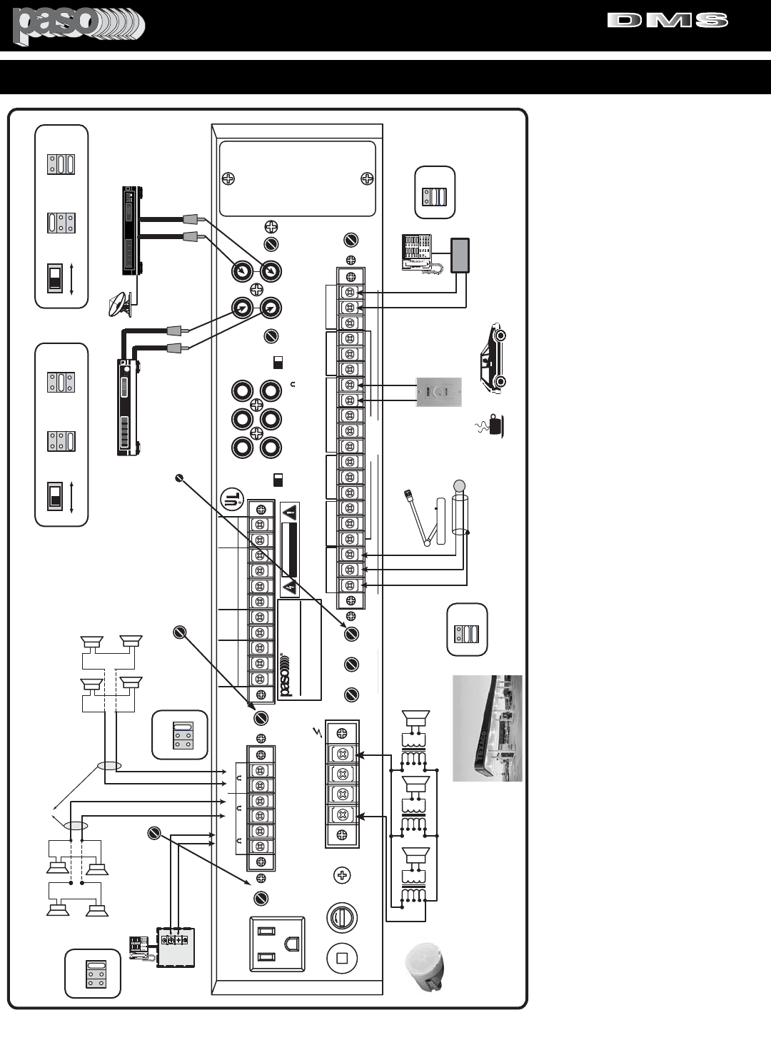
AUTO SERVICE STATION C - STORE - APP. DATA 123
PROFESSIONAL AUDIO & SOUND
®
TM
DIGITAL MUSIC SERIES
DIGITAL MUSIC AMPLIFIERS
PAGE 31
SPECIFICATIONS ARE SUBJECT TO CHANGE WITHOUT NOTICEDMS3040/3080/3120
SER. NO.
ATTENTION:
AFIN DE REDUIRE LE RISQUE
D'INCENDIE REMPLACER SEUL PAR UN
FUSIBLE DE MEME TYPE.
COM 8 25V 70V
SPEAKER OUTPUT
GROUND
LINE FUSE
5A 250V
117V 500W MAX
117V 60HZ
R
L
LEVEL LEVEL
EQ LINK
ATTENUATOR ATTENUATOR
VOX-1
UNSWITCHED
0 600
ZONE 2
ZONE 1 24V DC
250 mA
0 8 0 8
VOX-2 MUTE-2
SENS
SENS DELAY
IN OUT
TEL
G COM HOT
NC C NO
+-
MIC1 G M2 M1 RVC
VOX RELAY
GROUND
UNMUTE
MUTE 1
MUTE 2
47kohm 100mV
(AUX1) (AUX2)
LEVEL
TEL OUTPUT
ZONE 2
ZONE 1
INPUT-4(AUX1)
BALANCED
INPUT 5
MIC-AUX2
BY INTERNAL
SWITCH
250ohm 1.5mV
47kohm 100mV
INPUT-5(AUX2)
ON OFF
POWER RATING
SUPPLY VOLTAGE
POWER CONSUMPTION
120 W RMS
117V 60 HZ
850 VA
DMS3120
LISTED
COMMERCIAL
AUDIO
EQUIPMENT
30TJ
CUS
MIX
BUSS
LINE OUT
600
PRE
OUT
POWER
IN
SUB OUT
PRE EQ
SUB OUT
POST EQ TONE
BYPASS
CAUTION: TO REDUCE THE RISK OF FIRE OR
SHOCK DO NOT EXPOSE THIS APPLIANCE TO
RAIN OR MOISTURE. DO NOT REMOVE COVER.
THERE ARE NO USER SERVICEABLE PARTS
INSIDE. REFER SERVICING TO QUALIFIED
SERVICE PERSONNEL.
DIGITAL MUSIC AMPLIFIER
CAUTION: TO REDUCE THE
RISK OF FIRE, REPLACE
ONLY WITH SAME TYPE
FUSE.
MOH OUT
BALANCED
MASTER
REMOTE
VOLUME
EQ LINK
PORT ACCEPTS
STANDARD
MODULE
CAUTION: REMOVE
POWER CORD FROM
AC OUTLET PRIOR TO
INSTALLING MODULE
CAUTION
RISK OF ELECTRIC SHOCK
DO NOT OPEN
WARNING: THIS APPLIANCE
MUST BE EARTHED
ATTENTION: POUR REDUIRLES RISQUES D' INCENDIE
OU DE CHOC ELECTRIQUE, NE PAS EXPOSER A LA PLUIE
OU L' HUMIDITE, NE PAS ENLEVER LE COUVERCLE. AUCUN
REGLAGE A L' INTERIEUR. POUR REPARATION CONSULTER
UNE PERSONNE QUALIFIEE
INPUT 4 (MIC) INPUT 3 (MIC)
INPUT 2 (MIC)
INPUT 1 (MIC)
G COM HOT RVC RVC G COM HOT G COM HOT G COM HOT G COM HOT
INPUT 4
REMOTE
VOLUME
RVC
PROFESSIONAL AUDIO & SOUND
DMS3120rear
1 WATT 1 WATT
AUX2
47Kohm 100 mV
INPUT5 (MIC-AUX2)
600 ohm 100mV
MOH
Input
600
Ohm
Telephone System
KSU
600 ohm MOH System
Telephone
1/4W
1/4W
1/4W
1/4W
8
OHM
ZONE 2 8
OHM
8
OHM 8
OHM
MUSIC ON HOLD OUTPUT
Up to Four 8 ohm
Speakers may be
connected
MUSIC ON HOLD
RECEIVES MUSIC
ONLY - NO PAGING
NO MESSAGE REPEATER
Phone Paging
KSU
INPUT 4
REMOTE
VOLUME
25V/70V Speaker 25V/70V Speaker 25V/70V Speaker
SATELLITE RECEIVER
SHIELD
b50side
Push to Talk Key
MIC
LO Z
PAGING MICROPHONE
MICROPHONE HAS
PRIORITY OVER
SATELLITE RECEIVER
AND MESSAGE
REPEATER
MESSAGE
REPEATER
REMOTE
VOLUME
RL
R
L
TIP
RING
PHONE HAS
PRIORITY OVER
MUSIC
AND MESSAGE
REPEATER
OPTIONAL MUSIC
ONLY ZONE
MUSIC
SOURCE
MUTE-2
DELAY
3 to 30 Sec
OPTIONAL
PASO RVC10W
INPUT 1 (MIC 1) SETTINGS
OFF
SW212
VOX 2 ON
V1
V2
VOX JUMPERS
INPUT 4 (AUX 1) SETTINGS
OFF
SW217
MUTE 1 ON
M1
M2
MUTE JUMPERS
AUX 1 MIC 4
SW228
AUX 1 - MIC 4 SWITCH
SW208 and SW229
OFF
SW213
VOX 2 OFF
V1
V2
VOX JUMPERS
INPUT 5 (AUX 2) SETTINGS
OFF
SW223
MUTE 1 ON
M1
M2
MUTE JUMPERS
AUX 2 MIC 5
AUX 2 - MIC 5 SWITCH
VOX 1 OFF
MUTE 2 ON
OFF
SW214
VOX 1 ON
VOX 2 ON
V1
V2
VOX JUMPERS
TEL INPUT SETTINGS
SW702
AUX 1
ZONE 1 MOH SETTING
AUX 2
MOD
MUTE 2 DELAY CONTROL
ADJUSTS MESSAGE
REPEATER MUTING TIME
OVER SATELLITE
RECEIVER
OFF
SW215
VOX 1 ON
VOX 2 ON
V1
V2
VOX JUMPERS
SW701
AUX 1
ZONE 2 SOURCE SETTING
AUX 2
MOD
ZONE 2 LEVEL CONTROL
ADJUSTS OUTPUT
LEVEL OF ZONE 2
SPEAKERS
ZONE 2
LEVEL
MESSAGE REPEATER
MESSAGES MUTE
MUSIC AT THE PUMPS
GAS PUMP SPEAKERS - MUSIC/MESSAGES AND PAGING
PASO
C55DMSTW - White
Waterproof Speaker
CEILING SPEAKERS MOUNTED INSIDE C-STORE
The Amplifier provides two independent 1 Watt-8 Ohm Outputs.
Up to 4-8 ohm Speakers may be connected to each Output.
The use of both Outputs is optional follow the
individual requirement.
CEILING SPEAKERS MOUNTED INSIDE C-STORE RECEIVE MUSIC ONLY - NO MESSAGES OR PAGING
1/4W
1/4W
1/4W
1/4W
8
OHM
8
OHM
8
OHM 8
OHM
ZONE 1
OPTIONAL MUSIC
ONLY ZONE
ZONE 1
LEVEL
AWG 18
TWISTED PAIR
PASO MODEL B500X MICROPHONE
DMS C-STORE APP 123
JUMPER
JUMPER
JUMPER
JUMPER
JUMPER
JUMPER
JUMPER
JUMPER
JUMPER
JUMPER
JUMPER
APPLICATION
This Note illustrates a typical Auto Service Station
C-Store application. The size of the Service
Station and the number of Gas Pump Islands to
cover will determine the amount of outdoor
Waterproof Speakers required and the Power
Output of the Amplifier.
GAS PUMP OUTDOOR SPEAKERS
40 WATT SYSTEM EXAMPLE - The PASO Model
C55DMST Waterproof Music Speaker is recom-
mended.Typically each Speaker should be tapped
at 5 Watt. In this configuration up to 8 Speaker
may be used with the Model DMS3040 40 Watt
Amplifier for distribution of Music and Messages
at the Gas Pumps.
For larger systems use a higher power Amplifier
and the additional quantity of speakers required.
C _ STORE INDOOR SPEAKERS
The Amplifier is equipped with two independent 1
Watt , 8 ohm Amplifiers = ZONE 1 and ZONE 2.
C-STORE - Up to 4+4 Ceiling Speakers may be
utilized indoors in the Store area, Rest Rooms or
other area such as a separate concession. By uti-
lizing the separate (2) 1 Watt Amplifiers as a first
and second zone, only the Music program will be
distributed inside the Store. This avoids the con-
tinuous and annoying repeating of the messages
in the indoor areas. The output level may be
adjusted by the 1st and 2nd Zone Level Control.
ZONE 1 - ZONE 2 PROGRAM SOURCE SELEC-
TOR
The program Source for each Zone Output may
be selected by setting the Zone 1 and 2 Jumper
Set to either AUX 1 - AUX 2 or Module Source.
MUSIC ON HOLD
The Zone 1 Amplifier provides a separate 600
ohm Transformer Balanced Music on Hold Output
for the Telephone system. If the Zone 1 Input
Select Jumper Set is set to AUX 1, the MOH
Output receives the Music from the Satellite
Receiver without Paging or Messages interrup-
tions.
PAGING MICROPHONE
PRIORITY PAGING MICROPHONE - A Low
Impedance Dynamic Microphone can be connect-
ed to the Amplifier INPUT 1. The Microphone can
be set to provide
Priority Paging
over both the
Music Program and the Message Repeater.
Optionally Paging may be generated from the
Phone system if desired.The TEL INPUT provides
a 600 ohm Transformer balanced Phone interface.
MESSAGE REPEATER
The Message Repeater provides pre-recorded
Messages at the
Gas Pumps Only
. Each time a
message is initiated by the Repeater (AUX 1) the
Music (AUX 2) is automatically muted for the dura-
tion of the message.
REPEATER REMOTE VOLUME
A Master Remote Volume Control PASO Model
RVC10W may be provided to adjust the Output
Level of the Message Repeater in accordance to
the outdoors noise.

CUSTOMER SERVICE
PAGE BACK
REPLACEMENT PARTS
Please provide complete information when you request replace-
ment parts from either the Factory or a Paso Authorized
Distributor. Be certain to include the Part Number and
Description as it appears on the parts list, the Model Number of
the unit and if possible the Serial Number and the date of pur-
chase of the unit. Replacement parts inventory is maintained
specifically to repair Paso products. Part sales for other reasons
or applications will be declined.
ORDERING FROM THE FACTORY
Print all information on a purchase order form and mail to:
PASO SOUND PRODUCTS, INC.
4750 Goer Drive - Building F
CHARLESTON, SC 29406
Be sure to include the following:
- Paso part number
- Part description
- Quantity required
- Model number of the unit
- Serial number of the unit
- Your payment or your authorization for COD shipment for parts
not covered by the Warranty or if your company has a current
account with the factory
RETAIN ORIGINAL IN WARRANTY PARTS UNTIL YOU
RECEIVE REPLACEMENTS. PARTS THAT SHOULD BE
RETURNED TO THE FACTORY WILL BE LISTED ON YOUR
PACKING SLIP.
For your convenience replacement parts are also available
through Paso Authorized Distributors and Dealers nation wide.
Obtain a location list directly from the Factory or your regional
Paso Representative.
TECHNICAL CONSULTATION
- Need help with your installation ?
- Need help with the operation of the unit ?
- Need help with a repair ?
Call or write for assistance. You will find our Technical Dept..
eager to help or assist you with any technical problem you may
have encountered except “`Customizing'' for a unique applica-
tion.
The effectiveness of our consultation service depends on
the accuracy of the information you furnish.
Be sure to tell us:
- The Model and Serial number of the unit
- The date of purchase
- An exact description of the difficulty
- All you have done in attempting to correct the problem
Call our toll-free phone number:
1-800 231 3034
REPAIR SERVICE
REPAIR SERVICE
Repair service for out of warranty Paso products may be
obtained form your local Paso distributor or any other qualified
repair station.
In warranty repairs must be returned to the Factory.
Prior authorization must be obtained from the Factory.
Products received without authorization will be refused by our
Receiving Dept..
IN WARRANTY REPAIR SERVICE
Call or write the Factory to obtain an authorization to return
the product for repairs.
Pack the equipment in the original carton or in a strong carton
with at least THREE INCHES of resilient packing material on all
sides, top and bottom. Seal the carton with reinforced tape and
mark it FRAGILE on at least two sides. Remember, the Carrier
will not accept liability for shipping damages if the unit is improp-
erly packed.
EQUIPMENT RECEIVED IN DAMAGED CONDITION DUE TO
POOR PACKING WILL BE REFUSED AND THE WARRANTY
COVERAGE IS AUTOMATICALLY VOIDED.
The Paso Sound Limited Warranty provides:
The examination of the returned product must disclose in our
judgement, a manufacturing defect. The warranty does not
extend to any product that has been subject to misuse, neglect,
accident, improper installation or where the serial number of the
product has been removed or defaced.
Ship via insured prepaid United Parcel Service or Parcel Post to:
PASO SOUND PRODUCTS, INC.
4750 Goer Drive - Building F
CHARLESTON, SC 29406
Attn. SERVICE DEPARTMENT
The equipment will be returned freight prepaid after repairs.
Be sure to include the following:
- Your name and address
- Date of purchase and copy of invoice
- A brief description of the difficulty
- A return address shipping label
-
OUT OF WARRANTY REPAIR SERVICE
Follow return instructions as per in warranty repair service. Prior
to performing all necessary repairs, you will be advised of the
charges and at that time a written authorization by you will be
required including authorization to return the equipment COD for
the service and shipping charges. This will avoid unnecessary
delays in returning the equipment to you.
Printed in USA Manual OM 163
PROFESSIONAL AUDIO & SOUND
®
TM
DIGITAL MUSIC SERIES
DIGITAL MUSIC AMPLIFIERS
