User Manual

Transponder Reader
TWN3
Technical Manual
Doc.-Rev. 1.12

Elatec GmbH
Page 2 of 62
Content
1. FUNCTIONAL OVERVIEW ...................................................................................................................... 4
2. MODES OF OPERATION .......................................................................................................................... 5
2.1 USB-DEVICE ........................................................................................................................................... 6
2.1.1 Keyboard Emulation (USB HID Device) ........................................................................................ 6
2.1.2 Emulating a Virtual Serial Port ...................................................................................................... 6
2.2 RS232-DEVICE ........................................................................................................................................ 6
2.2.1 Serial Communication Parameters ................................................................................................. 6
2.2.2 Pin Assignment ................................................................................................................................ 7
3. INSTALLATION .......................................................................................................................................... 7
3.1 RS232-DEVICE ........................................................................................................................................ 7
3.2 USB-DEVICE (KEYBOARD EMULATION) .................................................................................................. 8
3.3 USB-DEVICE (VIRTUAL SERIAL PORT) .................................................................................................... 8
4. CONFIGURATION .................................................................................................................................... 10
4.1 ENTERING THE CONFIGURATION MODE.................................................................................................. 11
4.2 WRITING A CONFIGURATION TO A TWN3 DEVICE ................................................................................. 12
4.3 RESUMING NORMAL OPERATION ........................................................................................................... 13
4.4 SELECTING MODE OF OPERATION .......................................................................................................... 14
4.5 SETTING UP THE KEYBOARD EMULATION .............................................................................................. 15
4.5.1 Table of Scan Codes ...................................................................................................................... 15
4.5.2 Sending ALT Codes ....................................................................................................................... 17
4.5.3 Key Repeat Rate ............................................................................................................................ 17
4.6 INSTALLING SCRIPTS .............................................................................................................................. 18
4.7 RS232 SETTINGS .................................................................................................................................... 20
4.8 STARTUP CONDITION IN TRANSPARENT MODE....................................................................................... 21
4.9 UPDATING THE FIRMWARE ..................................................................................................................... 22
4.10 PREFERENCES ........................................................................................................................................ 23
4.11 EXPORT AND IMPORT OF CONFIGURATIONS ........................................................................................... 24
4.12 INSTALLING USB-DRIVERS FOR CONFIGURATION .................................................................................. 25
5. TRANSPARENT MODE ........................................................................................................................... 26
5.1 HID PROX TRANSPARENT PROTOCOL .................................................................................................... 27
5.2 INDITAG TRANSPARENT PROTOCOL ....................................................................................................... 27
5.3 CONTROLLING LEDS AND BEEPER ......................................................................................................... 28
5.3.1 Set LEDs ........................................................................................................................................ 28
5.3.2 Get LEDs ....................................................................................................................................... 29
5.3.3 Set Volume ..................................................................................................................................... 30
5.3.4 Beep ............................................................................................................................................... 31
6. SCRIPTING................................................................................................................................................. 32
6.1 LANGUAGE DESCRIPTION ....................................................................................................................... 32
6.1.1 Source Code .................................................................................................................................. 32
6.1.2 Comments ...................................................................................................................................... 32
6.1.3 Case Sensitivity ............................................................................................................................. 32
6.1.4 Preprocessor Directives ................................................................................................................ 32
6.1.5 Functions ....................................................................................................................................... 33
6.1.6 Statements ..................................................................................................................................... 34
6.1.7 Storage Types ................................................................................................................................ 36
6.1.8 Storage Classes ............................................................................................................................. 37
6.1.9 Operators ...................................................................................................................................... 38
6.2 RUNTIME ENVIRONMENT ....................................................................................................................... 39
6.2.1 Include File ................................................................................................................................... 39
6.2.2 Basic Definitions ........................................................................................................................... 39
6.2.3 Bit Fields ....................................................................................................................................... 39
6.2.4 Startup Condition .......................................................................................................................... 39

Elatec GmbH
Page 3 of 62
6.2.5 System Function Calls ................................................................................................................... 40
7. FIRMWARE HISTORY ............................................................................................................................ 59
8. TECHNICAL DATA .................................................................................................................................. 60
9. REGULATORY INFORMATION ............................................................................................................ 60
9.1 CE DECLARATION OF CONFORMITY ....................................................................................................... 60
9.2 FCC STATEMENT ................................................................................................................................... 61
9.3 IC (INDUSTRY CANADA) STATEMENT .................................................................................................... 61
10. TRADEMARKS ...................................................................................................................................... 62

Elatec GmbH
Page 4 of 62
Introduction
This document is the reference guide for the transponder reader family TWN3.
Note:
In order to use the functionality, which is described in this document, your TWN3 reader needs
a firmware version V4.00 or above. The latest version of the firmware is part of the developer
pack. Please revere to section “Updating the Firmware”, if you would like to update the
firmware.
1. Functional Overview
Here is a block diagram of the basic functional components of a TWN3 transponder reader:
Multi125
Mifare HID Prox
HID iClass
Transponder Family Depending On Type of Device
Transparent Communication Script Controlled Operation
Physical COM Port Virtual COM Port Keyboard
Emulation
USB-InterfaceV24-Interface
TWN3 Transponder Reader
Legic
InditagMultiISO
Legic NFCMifare NFC
Elatec GmbH
Page 5 of 62
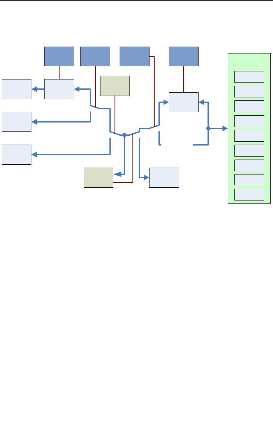
Let‟s take a more detailed view:
The diagram below is showing the functional units and how they can be configured:
V24-
Interface
Scripting
Engine
Multi125
Mifare
HID Prox
HID iClass
Legic
Transparent
Communication
Config
Mode
Command
for Config
Mode
TWNConfig
Selected by
Cable
TWNConfig
Scancode
Translation
Table
USB Virtual
COM Port
USB
Keyboard
Emulation
TWNConfig TWNConfig TWN3
Device Type
IndiTag
MultiISO
Mifare NFC
Legic NFC
2. Modes of Operation
The transponder reader TWN3 can be ordered in several hardware configurations:
Support for the specific transponder family (Multi125, Mifare, Mifare NFC, HID Prox,
HID iClass, Legic, Legic NFC, IndiTag, MultiISO)
Physical type of connection (type of cable) to the host computer: USB or RS232, DSUB25,
DSUB9 or PS/2
Many other configurations can be done by the system integrator:
Type of USB mode (USB devices only)
Behavior of keyboard emulation
Scripting mode

Elatec GmbH
Page 6 of 62
2.1 USB-Device
A TWN3 USB reader is capable of supporting several modes of operation:
2.1.1 Keyboard Emulation (USB HID Device)
This is the default mode for USB devices. No drivers are required for running the device in a typical
environment like Windows XP or Linux. Any output from the TWN3 transponder reader to the host is
sent like keyboard input from a user. Therefore, any characters are displayed at the current position of
the cursor on the screen of the computer.
Please be aware, that the communication between TWN3 device and host computer is unidirectional.
This means, there is no possibility to send data from the host to the TWN3 device. In situations where
this is required, we recommend the emulation of a serial port.
2.1.2 Emulating a Virtual Serial Port
Optionally, a USB device can be configured to emulate a virtual serial port. This mode of operation is to
be preferred, if a direct communication between application and TWN3 transponder reader is required.
This mode also enables a bidirectional communication between .
The communication protocol is identical to the version of TWN3 reader with a physical RS232
interface.
2.2 RS232-Device
2.2.1 Serial Communication Parameters
These are the default communication parameters for RS232 devices. Baudrate and parity can be
configured as follows:
Parameter
Default Value
Optional Values
Baudrate
9600 Baud
1200 Baud, 2400 Baud,
4800 Baud, 9600 Baud,
19200 Baud, 38400 Baud,
57600 Baud
Databits
8
-
Parity
None
(Even parity for TWN3 Multi125 in
transparent mode)
None, Even, Odd
Stopbits
1
-
Handshake
None
-

Elatec GmbH
Page 7 of 62
2.2.2 Pin Assignment
Following pin assignment for the DSUB25 plug:
Pin
Signal
2
RxD from host
3
TxD to host
7
Signal ground
24
5V power supply from the host
Following pin assignment for the DSUB9 plug:
Pin
Signal
3
RxD from host
2
TxD to host
5
Signal ground
9
5V power supply from the host
Following pin assignment for the PS/2 plug:
Pin
Signal
6
RxD from host
2
TxD to host
3
Signal ground
4
5V power supply from the host
3. Installation
3.1 RS232-Device
Installing a TWN3 reader with a serial port requires an additional power supply, which is not standard
for usual PCs. On the other hand, many devices do supply the 5V on a rarely used pin of the serial
connector. Please contact your supplier for a specific solution.
The installation of the reader is as simple as connecting a USB device to a host.
Elatec GmbH
Page 8 of 62
3.2 USB-Device (Keyboard Emulation)
Installing a TWN3 reader emulating a keyboard is rather simple due to the fact, that drivers do come
with the operating system. Therefore, the device simply can be connected to the host computer and
can be immediately used.
3.3 USB-Device (Virtual Serial Port)
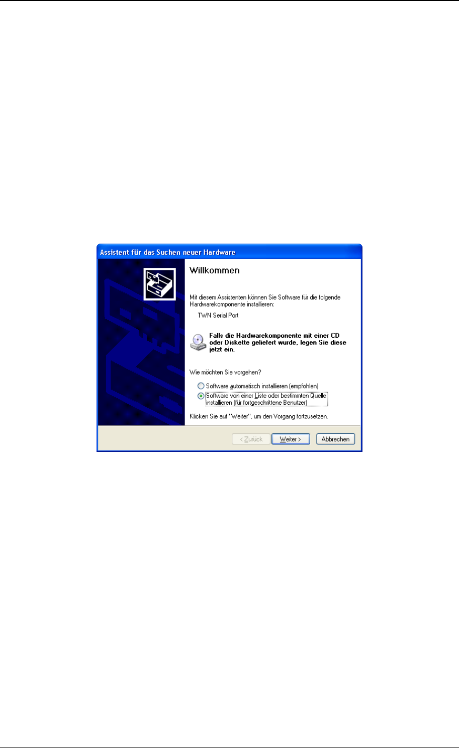
In order to install a TWN3 reader, which emulates a virtual serial port under Windows XP, keep the
drivers nearby and follow these steps:
Plug in the TWN3 reader into your host computer. The following screen should appear (in your
native language)
Select to install the software from a specific source.

Elatec GmbH
Page 9 of 62
The following screen should appear:
Select the directory, where the drivers reside and click continue. The drivers will be installed
now.
After installation, the following screen should appear:
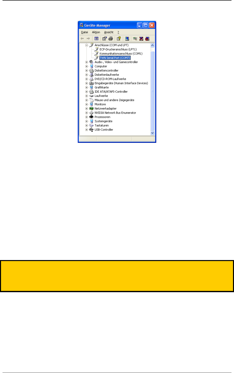
The installation is now completed. In order to find the serial communication port, which is emulated by
the TWN3 transponder reader, you may take a look into the device manager:
Elatec GmbH
Page 10 of 62
In this example, we find the TWN3 reader at COM7.
Depending on the further configuration of the device, you may now test the TWN3 transponder reader
with a normal terminal program.
4. Configuration
In order to configure a TWN3 transponder reader, the program TWNConfig.exe is required.
Configuration is supported under Windows XP or Windows Vista. During configuration, a TWN3
transponder reader is switched into configuration mode. In this mode the entire setup of the device can
be done. Configuration is possible both for RS232 and USB devices.
Note:
Please do not connect more than one TWN3 device at a time to your computer during the usage
of TWNConfig. This ensures the knowledge about the TWN3 device which is actually to be
configured.

Elatec GmbH
Page 11 of 62
4.1 Entering the Configuration Mode
Assuming, that the TWN3 transponder reader is already connected to the host computer, start the
program TWNConfig.exe. The following screen will appear:
Depending on the physical interface of the TWN3 transponder reader, choose the appropriate port in
the top left combo box. Click the “Connect”-button:

Elatec GmbH
Page 12 of 62
TWNConfig is searching and connecting to a TWN3 device. You are now ready to do the required
configurations on the device.
Note:
If you are configuring a USB device the first time, you have to install the appropriate
configuration drivers. Please refer to “Installing USB-Drivers for Configuration”.
4.2 Writing a Configuration to a TWN3 Device
Once a configuration has been set up completely (either via importing a configuration or manually via
the tab folders), the configuration can be written back to the TWN3 device. This will save the
configuration permanently in the TWN3 device. In order to do that, click the button “Write Config”.

Elatec GmbH
Page 13 of 62
4.3 Resuming Normal Operation
In order to leave the configuration mode of the TWN3 device and resume to normal operation click the
“Restart” button.
Note:
Disconnecting the device from the host or a power cycle will keep the device in configuration
mode!

Elatec GmbH
Page 14 of 62
4.4 Selecting Mode of Operation
In the tab folder “Mode of Operation” you select the basic mode in which the TWN3 device operates.
This setup is used both for USB and RS232 devices:
TWN3 USB
TWN3 RS232
Intelligent Virtual COM Port:
Run a script on the TWN3 device
(“intelligent”) and emulate a COM port
Intelligent Operation:
Run a script on the TWN3 device
(“intelligent”)
Intelligent Keyboard Emulation:
Run a script on the TWN3 device
(“intelligent”) and emulate a keyboard
Intelligent Operation:
Run a script on the TWN3 device
(“intelligent”)
Transparent Virtual COM Port:
Establish a direct link between the virtual
COM port and the internal transponder
reading module.
Transparent Operation
Establish a direct link between the serial
port and the internal transponder reading
module.

Elatec GmbH
Page 15 of 62
4.5 Setting Up the Keyboard Emulation
4.5.1 Table of Scan Codes
This tab folder enables you to change the scan codes of the keyboard emulation, which are sent to the
host for a specific character. The default setup of the device already contains the often used
characters „0‟ – „9‟, „A‟ – „F‟, carriage return and the space character.
There are some reasons, why you may want to change the existing setup:
You need a setup for a specific country, where the layout of a keyboard is different from the
default one.
You need some additional keys in order to achieve your specific format to be sent to the host.
This might be an additional space or a tab instead of return.

Elatec GmbH
Page 16 of 62
In order to do this, you may double-click on an existing entry in the table or specify a new entry by
pressing the “Add”-button. In the following dialog you now are able to select the appropriate keys.
Please keep in mind, that the keyboard keys are to be specified in relation to a standard U.S. QUERTY
keyboard, which is shown below:
Source: www.wikipedia.org
Notes:
A maximum of 48 entries in the scan code table is possible.
Instead of specifying a key on the keyboard, sending the appropriate ASCII as ALT code
can be configured.

Elatec GmbH
Page 17 of 62
4.5.2 Sending ALT Codes
You may send ALT codes instead of key strokes on a keyboard.
Example:
The character „A‟ (ASCII code 65) should be sent to the host. Following sequence is executed:
- Press ALT key
- Press key „6‟ on the numeric keypad
- Release key „6‟ on the numeric keypad
- Press key „5‟ on the numeric keypad
- Release key „5‟ on the numeric keypad
- Release ALT key.
There are advantages and disadvantages in doing so:
Advantages:
There is no table of keystrokes necessary, which have to be set up. All characters with ASCII
codes in the range from 1 to 255 can be sent.
No adaptations to different keyboard layouts are necessary.
Disadvantage:
Some programs do not accept sending ALT codes and react in a complete different way.
The amount of key strokes is higher. Therefore, the maximum transfer speed is slower.
4.5.3 Key Repeat Rate
The repeat rate, with which key strokes are sent to the host can be adjusted. The time between key
strokes is specified in multiples of milliseconds.

Elatec GmbH
Page 18 of 62
4.6 Installing Scripts
In order to install a script on a TWN3 device, perform following actions:
Select the tab folder “Scripting”.
Select a script file (extension “.twn.c”) by clicking the button “Select Script”.
Click the “Compile Script”. This will start the script compiler.
If there is an error detected in the script, the line number and type of error will be displayed.

Elatec GmbH
Page 19 of 62
If the compilation is successful, following screen will appear:
The compiled script is now part of the configuration within TWNConfig. Some additional information is
displayed on how much storage space is occupied by this script. Up to now, the script has not been
saved to the TWN3 device.

Elatec GmbH
Page 20 of 62
4.7 RS232 Settings
Within the tab folder “RS232”, you can setup the parameters for the RS232 communication parameters
to the host computer.
As long as the checkbox “Default Settings” is activated the device will communicate with 9600 Baud
and no parity (except version Multi125 which is using even parity in transparent mode).
Unchecking the checkbox “Default Settings” will force the device to communicate with the desired baud
rate and parity both in scripted and transparent mode.
The checkbox “Append Line Feed after Carriage Return” is related to a serial communication where
the host computer expects an additional line feed after every carriage return sent to the host.
A line feed will only be appended if:
o This options is selected
o The device is in intelligent mode (“running a script”)
o The device is connected via RS232 interface or via USB and emulating a virtual serial
port.
This setting has no influence, if the device is running in keyboard emulation.
This setting has no influence in transparent communication.
Elatec GmbH
Page 21 of 62
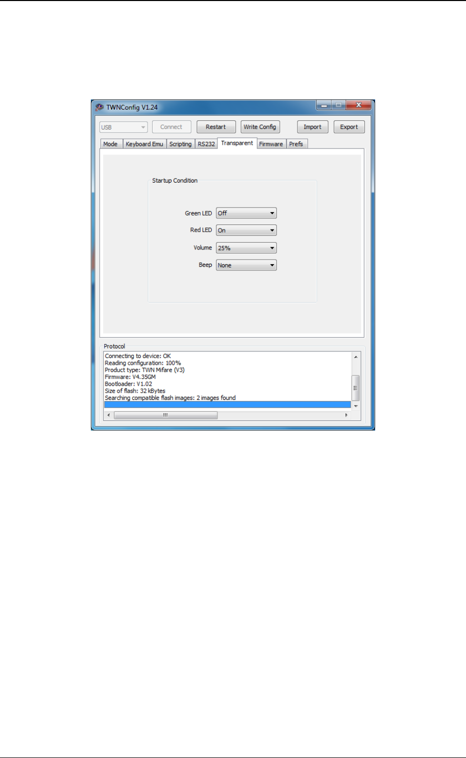
4.8 Startup Condition in Transparent Mode
Within the tab folder “Transparent”, you can setup the state of LEDs an beeper during startup of the
device.
The default setup is:
Green LED off
Red LED on
Volume 25%
No beep at startup

Elatec GmbH
Page 22 of 62
4.9 Updating the Firmware
In order to update the firmware of a TWN3 device select tab folder “Firmware”.
After any successful connection to a TWN3 device, the current directory will be searched for firmware
images, which are compatible to the connected device. In order to re-program the firmware of a TWN3
device, click the “Program”-button. After successful programming, the following screen should be
displayed:
Notes:
If programming fails for any reason (blackout or whatever), it is possible to restart the
programming process. The TWN3 device can only be brought back to normal operation
after successful programming of the firmware.
Older versions of TWN3 readers may contain a microcontroller, which can not be
programmed with the latest firmware due to limited storage capacity. In order to retrieve

Elatec GmbH
Page 23 of 62
storage capacity, the firmware version 4.09 should be programmed into the device first.
This firmware fits into any TWN3 device. TWNConfig is then able to determine the
storage capacity of the device.
Note:
Do not use an earlier version of TWNConfig than V1.15 for programming a firmware version
later than V4.09!
4.10 Preferences
Within the tab folder “Prefs”, there are two settings:
Activating the check box “Log protocol into file TWNConfig.log” will save all output, which
appears in the list box “Protocol”, into the file “TWNConfig.log”. The file is located in the folder
where TWNConfig resides.
Activating the checkbox “Slow down start of bootloader” will do a somewhat slower activation
of the boot loader of a TWN3 device. This may prevent from problems during activation of the
boot loader, which have been seen on specific PCs.

Elatec GmbH
Page 24 of 62
4.11 Export and Import of Configurations
Once a device has been configured completely, this configuration can be exported to a file. This makes
it much easier to setup many TWN3 devices with identical configuration.
Note:
It is not possible to read the secret area from a TWN3 device. To save a configuration
including their secrets, you have to compile the appropriate script, which defines these
secrets. After successful compilation of this script you are able to export the
configuration including script and secrets.
Be aware, that the configuration file also contains the secrets now so this file should be
handled as carefully as the source code of the script.

Elatec GmbH
Page 25 of 62
4.12 Installing USB-Drivers for Configuration
If the USB TWN3 reader is configured the first time, USB drivers for the configuration mode have to be
installed. Here are the steps to do so:
Once you have clicked the “Connect”-button within TWNConfig.exe the first time, the following
screen will appear:
Select to install the software from a specific source.
The following screen should appear:
Select the directory, where the drivers reside and click continue. The drivers will be installed
now.
After installation, the following screen should appear:

Elatec GmbH
Page 26 of 62
You are now ready to configure the TWN3 reader.
Note:
If the TWN3 reader is plugged into a different USB port of the host computer, this installation
procedure has to be repeated.
5. Transparent Mode
Once a TWN3 device has been turned into transparent mode, a direct link will be established between
the serial interface (RS232 or virtual USB), and the reading module. The direct communication with a
transponder reader module is not compatible to each other and requires the knowledge of the specific
communication protocol. Please see the following documents for related information:
TWN3 Type
Document
Multi125
T4T5Handbook x.xx.pdf
Mifare
TH_Mifare_x.xx.pdf
Mifare NFC
TH_Mifare_NFC_x.xx.pdf
MultiISO
TH_MultiISO_x.xx.pdf
IndiTag
This Document
HID Prox
This Document
HID iClass
Please contact your supplier for detailed
information.
Legic
Please contact your supplier for detailed
information.
Legic NFC
Please contact your supplier for detailed
information.

Elatec GmbH
Page 27 of 62
5.1 HID Prox Transparent Protocol
Due to the fact, the TWN3 HID Prox performs read access only, there are no commands available,
which can be sent to the reading module. The data received from the module is formatted as follows:
If a transponder is read, a ASCII string is sent which is terminated by carriage return.
The first character represents the number of valid bits, the remaining bytes do contain these
bits.
Two hexadecimal digits represent one byte.
The first byte specifies the number of valid bits in the following ID.
The remaining bytes do contain the ID itself.
Example:
Data sent by the reader:
1A808001C0<CR>
The first byte is 0x1A, 26 decimal. There are four bytes necessary to transport 26 bits. These bytes do
contain:
Byte
1
2
3
4
Byte Value
0x80
0x80
0x01
0xC0
Bit Values
1000 0000
1000 0000
0000 0001
11(00 0000)
Please note, that the unused bits are the lowest significant bits of the last bytes.
5.2 IndiTag Transparent Protocol
Due to the fact, the TWN3 IndiTag performs read access only, there are no commands available,
which can be sent to the reading module. The data received from the module is formatted as follows:
If a transponder is read, a ASCII string is sent which is terminated by carriage return and line
feed.
A line always starts with a colon.
The following characters represent the ID and a trailing checksum.
Two hexadecimal digits represent one byte.
The checksum is the 2nd complement of the addition of the ID bytes.
Example:
Data sent by the reader:
:112233445501<CR><LF>
The ID is 1122334455 (hexadecimal) and the checksum is 01 (hexadecimal)

Elatec GmbH
Page 28 of 62
5.3 Controlling LEDs and Beeper
Even in transparent mode there are commands available, which allow control of the built-in LEDs and
the beeper. The commands depend on the communication protocol of the built-in reader module.
Please Note:
The parameters and return values are identical to the corresponding system calls LEDSet,
LEDGet, SetVolume and Beep.
Please see the related documents for a detailed description of the communication in
transparent mode.
In order to use these commands, the firmware version V4.20 or later is required.
5.3.1 Set LEDs
Please see the system function call LEDSet for a detailed description of the parameters.
TWN3 Type
Multi125
Command:
<0x06><0xFF><0xE8><LEDs><Status><BCC>
Response:
<0x05><0x00><0xE8><0x00><BCC>
Mifare
Mifare NFC
MultiISO
Command:
“:l<LEDs><Status>CR
Response:
„S‟CRLF (success)
„?‟CRLF (error)
Inditag
HID Prox
Command:
“:l<LEDs><Status>CR
Response:
„S‟CR (success)
„?‟CR (error)
HID iClass
Command:
<0x80><0xE8><LEDs><Status><0x00>
Response:
<0x90><0x00>
Legic
Command:
<0x04><0xE8><LEDs><Status><LRC>
Response:
<0x03><0xE8><0x00><LRC>
Legic NFC
Command:
<0x04><0xE8><LEDs><Status><CRCHI><CRCLO>
Response:
<0x03><0xE8><0x00><CRCHI><CRCLO>

Elatec GmbH
Page 29 of 62
5.3.2 Get LEDs
Please see the system function call LEDGet for a detailed description of the parameter and the return
value.
TWN3 Type
Multi125
Command:
<0x05><0xFF><0xE9><LED><BCC>
Response:
<0x06><0x00><0xE9><0x00><LED Status><BCC>
Mifare
Mifare NFC
MultiISO
Command:
“:g<LED>CR
Response:
<LED Status>CRLF (success)
„?‟CRLF (error)
Inditag
HID Prox
Command:
“:g<LED>CR
Response:
<LED Status>CR (success)
„?‟CR (error)
HID iClass
Command:
<0x80><0xE9><LED><0x00><0x01>
Response:
<LED Status><0x90><0x00>
Legic
Command:
<0x03><0xE9><LED><LRC>
Response:
<0x04><0xE9><0x00><LED Status><LRC>
Legic NFC
Command:
<0x03><0xE9><LED><CRCHI><CRCLO>
Response:
<0x04><0xE9><0x00><LED Status><CRCHI><CRCLO>

Elatec GmbH
Page 30 of 62
5.3.3 Set Volume
Please see the system function call SetVolume for a detailed description of the parameter.
TWN3 Type
Multi125
Command:
<0x05><0xFF><0xEA><Volume><BCC>
Response:
<0x05><0x00><0xEA><0x00><BCC>
Mifare
Mifare NFC
MultiISO
Command:
“:v<Volume>CR
Response:
„S‟CRLF (success)
„?‟CRLF (error)
Inditag
HID Prox
Command:
“:v<Volume>CR
Response:
„S‟CR (success)
„?‟CR (error)
HID iClass
Command:
<0x80><0xEA><Volume><0x00><0x00>
<0x90><0x00>
Legic
Command:
<0x03><0xEA><Volume><LRC>
Response:
<0x03><0xEA><0x00><LRC>
Legic NFC
Command:
<0x03><0xEA><Volume><CRCHI><CRCLO>
Response:
<0x03><0xEA><0x00><CRCHI><CRCLO>

Elatec GmbH
Page 31 of 62
5.3.4 Beep
Please see the system function call Beep for a detailed description of the parameter.
TWN3 Type
Multi125
Command:
<0x05><0xFF><0xEB><Type><BCC>
Response:
<0x05><0x00><0xEB><0x00><BCC>
Mifare
Mifare NFC
MultiISO
Command:
“:b<Type>CR
Response:
„S‟CRLF (success)
„?‟CRLF (error)
Inditag
HID Prox
Command:
“:b<Type>CR
Response:
„S‟CR (success)
„?‟CR (error)
HID iClass
Command:
<0x80><0xEB><Type><0x00><0x00>
<0x90><0x00>
Legic
Command:
<0x03><0xEB><Type><LRC>
Response:
<0x03><0xEB><0x00><LRC>
Legic NFC
Command:
<0x04><0xEB><Type><CRCHI><CRCLO>
Response:
<0x04><0xEB><0x00><CRCHI><CRCLO>

Elatec GmbH
Page 32 of 62
6. Scripting
6.1 Language Description
The scripting language for TWN3 readers is a simplified version of the language C. The main
differences are:
There is one data type available, which is a byte. A byte is an unsigned integer with a size of
8 bits.
There are no pointers available. Instead, there is a reference operator, which is showing some
similarity to the language C++.
6.1.1 Source Code
The source for a TWN3 script is given as a text file. Due to closeness to the language C, the extension
should be “.c”. Doing so will give the advantage of a working syntax highlighting in many programming
editors. In order to distinguish normal C-code from TWN3 scripting code it is furthermore
recommended to expand the extension to “.twn.c”. This is also the default extension which is used
by the configuration tool TWNConfig. The preferred extension for include files is “.twn.h”.
A TWN3 script is one file of source. It is possible to include additional source files via a directive to the
preprocessor.
6.1.2 Comments
In order to place a comment within the source code, two slashes are used. The remaining content of
the line will be ignored by the compiler.
6.1.3 Case Sensitivity
The TWN3 script language is sensitive to upper and lower case. Examples:
byte a; // Valid
Byte a; // Invalid
byte Byte; // Valid(!)
6.1.4 Preprocessor Directives
The preprocessor is removing comments from the source code and processing the preprocessor
directives. Currently, there is one directive available.

Elatec GmbH
Page 33 of 62
6.1.4.1 #include Directive
Include another source file and treat it as a part of the compiled source. There are two possibilities:
#include <sys.twn.h>
Include the given file, which is located relative to the directory, where TWNConfig.exe resides.
#include “mydefs.twn.h”
Include the given file, which is located relative to the current directory
6.1.5 Functions
Functions may be defined (“prototype”) in order to resolve forward references, or declared directly.
The prototype of a function has the following form:
(byte | void) identifier([list of arguments]);
The declaration of a function has the following form:
(byte | void) identifier([list of arguments])
function body
The function body is a block of statements.
6.1.5.1 Return Values
A function either has a return value (byte) or not (void). Following form is required to return a value:
return expression;
6.1.5.2 Arguments
If a function has no arguments, the list of arguments has to be left empty (do not write void).
In order to declare arguments, write the list of arguments separated by commas. Arguments are
passed by value or by reference. In order to pass an argument by reference instead of value, insert the
„&‟ before the identifier of argument. Here are some examples of valid function prototypes:
void Func1(); // No arguments
void Func2(byte i); // A single argument,
// which is passed by value
void Func3(byte in, byte &out); // Two arguments, where in is passed by
// value and out is passed by reference
6.1.5.3 System Functions
A system function can only be declared as prototype. Following form:
(byte | void) identifier([list of arguments]) system number;
The list of available system functions is contained in the file sys.twn.h. For the script programmer there
is normally no need to declare system functions on his own.

Elatec GmbH
Page 34 of 62
6.1.5.4 Function main
A TWN3 script always needs the function main to be implemented. The prototype for the function main
is:
void main();
After internal initialization, the TWN3 reader will start execution of the script by calling this function
main.
6.1.6 Statements
A single statement has the form
[expression];
This means, a statement is a (optional) expression followed by a semicolon. If only a semicolon without
an expression is specified, it is called an empty statement. Statements can be enclosed by braces to
build a block of statements. A block statement can be used wherever a single statement can be used.
6.1.6.1 if Statement
An if statement has the form:
if (expression) statement
Statement is executed only if the result of expression is not equal to zero.
6.1.6.2 if else Statement
An if else statement has the form:
if (expression) statement1 else statement2
Statement1 is executed only, if the result of expression is not equal to zero. Otherwise, statement2 is
executed.
6.1.6.3 while Statement
A while statement has the form:
while (expression) statement
Statement is executed, as long as the result of expression is not equal to zero.
6.1.6.4 do while Statement
A do while statement has the form:
do statement while (expression);
Statement is executed, until the result of expression is equal to zero.

Elatec GmbH
Page 35 of 62
6.1.6.5 for Statement
A for statement has the form:
for ([expression1]; [expression2]; [expression3] statement
As first step, expression1 is evaluated. As long as expression2 is not equal to zero, statement is
executed. After execution of statement, expression3 is evaluated. Therefore, a for statement can be
rewritten as while statement with exactly the same behavior:
expression1;
while (expression2)
{
statement
expression3;
}
6.1.6.6 switch Statement
A switch statement has the form:
switch (expression)
{
[case constant expression: [case statement]]
[default: [default statement]]
}
The script is evaluating expression. Depending on the result of the expression the appropriate case is
executed. If there is no appropriate case, the default case is executed. If there is no default label,
execution is continued after the switch statement.
6.1.6.7 break Statement
Form:
break;
The break statement can be used in while, do/while, for and switch statements (loop or switch
statements).
In a loop statement, control is passed directly to the next statement outside of the loop. In a switch
statement, control is passed directly to the next statement outside of the switch body.
6.1.6.8 continue Statement
Form:
continue;
The continue statement can be used in while, do/while and for statements (loop statements). It directly
passes execution to the loop continuation portion of the loop statement.

Elatec GmbH
Page 36 of 62
6.1.6.9 return Statement
Two forms are possible:
Functions, which do not return a value:
return;
The execution of the current function is stopped. Execution is continued in the calling function.
Functions which return a value:
return expression;
Expression is evaluated, execution is stopped, the result of the expression is passed to the calling
function, execution is continued in the calling function.
6.1.6.10 goto Statement
Form:
goto label;
The goto statement directly passes execution to the position within a function, where the label
statement has been defined.
6.1.6.11 Labels
A label has the form:
identifier: statement
They may appear on any position within a function body. A label is used as destination for a goto
statement.
6.1.6.12 Empty Statement
A statement, which is doing nothing is the semicolon. Example:
for (i=0; i<10; i+=1) // Waste some time and do ten times nothing
;
6.1.7 Storage Types
In the TWN3 scripting language, there is only one type of storage defined, which is the byte. A byte is
an unsigned integer with a size of 8 bits.

Elatec GmbH
Page 37 of 62
6.1.8 Storage Classes
There are following storage classes available: Standard, const and secret. Without using any modifier,
the standard storage is used. A variable, which is declared in the standard storage class, is allocated in
the normal data segment.
Examples:
byte i; // A single integer
byte a[15]; // An array of 15 bytes
6.1.8.1 const
An identifier, which is declared as const can be used for calculations at compile time. There is no
physical memory occupied during runtime. Typically, you would use a const for defining constants,
which are used throughout a script for easier understanding and adaptation for different purposes.
Example:
const byte c = 15;
6.1.8.2 secret
The secret data space is a read-only segment. The content of this segment is written once during
programming the script into the TWN3 transponder reader. Furthermore, this segment can not be read
directly by the script itself. Therefore, there is no way to simply read the content of this memory and
send it to the host. There are only a few system functions, which take the content of this segment as
input. Typically, the secret data space is used for keys, which are necessary for authentication to a
transponder. Examples:
// Some well-known factory default keys for transponders
secret byte MifareKeyFF[6] = { 0xFF,0xFF,0xFF,0xFF,0xFF,0xFF };
secret byte MifareKeyAA[6] = { 0xA0,0xA1,0xA2,0xA3,0xA4,0xA5 };
secret byte MifareKeyBB[6] = { 0xB0,0xB1,0xB2,0xB3,0xB4,0xB5 };
secret byte Hitag2Key[4] = { 'M','I','K','R' };
secret byte EM4050Key[4] = { 0x00,0x00,0x00,0x00 };

Elatec GmbH
Page 38 of 62
6.1.9 Operators
Following operators are available:
Operator
Meaning
Example
()
Parenthesis
A = B * (C + D)
[]
Brackets
A = B[C]
!
Logical Not
A = !B
~
Bitwise Complement
A = ~B
-
Unary Minus
A = -B
+
Unary Plus
A = +B
*
Multiplication
A = B * C
/
Division
A = B / C
%
Modulus
A = B % C
+
Add
A = B + C
-
Subtract
A = B – C
<<
Shift Left
A = B << C
>>
Shift Right
A = B >> C
<
Lower
A = B < C
<=
Lower or Equal
A = B <= C
>
Greater
A = B > C
>=
Greater or Equal
A = B >= C
==
Equal
A = B == C
!=
Not Equal
A = B!= C
&
Binary And
A = B & C
^
Binary Exclusive Or
A = B ^ C
|
Binary Or
A = B | C
&&
Logical And
A = B && C
||
Logical Or
A = B || C
=
Assignment
A = B
+=
Addition/ Assignment
A += B
-=
Subtraction/ Assignment
A -= B
*=
Multiplication/ Assignment
A *= B
/=
Division/ Assignment
A /= B
%=
Modulus/ Assignment
A %= B
|=
Bitwise Or/ Assignment
A |= B
&=
Bitwise And/ Assignment
A &= B
^=
Bitwise Exclusive Or
A ^= B
<<=
Shift Left/ Assignment
A <<= B
>>=
Shift Right/ Assignment
A >>= B

Elatec GmbH
Page 39 of 62
6.2 Runtime Environment
6.2.1 Include File
The file sys.twn.h declares all constants and system function prototypes, which are necessary for
accessing the TWN3 transponder reader functionality. It is strongly recommended to include this file in
any TWN3 script:
#include <sys.twn.h>
6.2.2 Basic Definitions
In order to handle boolean operations in a more natural way, there are two constants defined:
const byte FALSE = 0;
const byte TRUE = 1;
System functions, which only return 0 or 1 in order to signal successful operation, are described to
return FALSE or TRUE for better readability.
6.2.3 Bit Fields
Many system functions operate on an array of bytes, where a count of bits is and/or a start bit is
specified. The table shows, how the bits are enumerated within the array of bytes:
Byte Index
0
1
2
Bit Index
0
1
2
3
4
5
6
7
8
9
10
11
12
13
14
15
16
17
18
19
20
21
22
23
Functions, which only specify a bitcount, operate on bits 0 to bitcount-1.
Functions, which specify a startbit and bitcount, operate on bits startbit to startbit+bitcount-1.
Please note, that both the most significant bits and the most significant bytes are still oriented to the left
side of the bit field.
6.2.4 Startup Condition
Following conditions are met, before a TWN3 script is started:
The entire variable data space is preset to 0.
All timers are stopped.
The LEDs are turned off.
The volume of the beeper is set to minimum level but not turned off (volume 1).
The communication with the transponder reading module is restarted.

Elatec GmbH
Page 40 of 62
6.2.5 System Function Calls
6.2.5.1 Transponder Operations
Following constants are defined for the various types of transponders which can be read by the family
of TWN3 transponder readers:
TWN3 Type
Transponder Definition
Corresponding
Value
Multi125
TAGTYPE_EM4102
TAGTYPE_HITAG1S
TAGTYPE_HITAG2
TAGTYPE_EM4150
TAGTYPE_ISOFDX
4
5
6
7
9
Mifare
TAGTYPE_MIFARE
1
Mifare NFC
TAGTYPE_MIFARE
TAGTYPE_ISO14443B
TAGTYPE_HIDICLASS
TAGTYPE_SRX
TAGTYPE_FELICA
1
23
20
25
24
HID Prox
TAGTYPE_HIDPROX
2
HID iClass
TAGTYPE_HIDICLASS
20
Legic
TAGTYPE_LEGIC
TAGTYPE_MIFARE
TAGTYPE_ISO15693
3
1
21
Legic NFC
TAGTYPE_LEGIC
TAGTYPE_MIFARE
TAGTYPE_ISO14443B
TAGTYPE_HIDICLASS
TAGTYPE_ISO15693
TAGTYPE_FELICA
3
1
23
20
21
24
IndiTag
TAGTYPE_INDITAG
22
MultiISO
TAGTYPE_MIFARE
TAGTYPE_ISO14443B
TAGTYPE_HIDICLASS
TAGTYPE_SRX
TAGTYPE_ISO15693
1
23
20
25
21

Elatec GmbH
Page 41 of 62
6.2.5.1.1 Generally Available Transponder Operations
byte TagSearch(byte &IDData, byte &IDBitCnt, byte &TagType)
Search a transponder. This function behaves similar on different types of transponder readers, but not
identical.
Parameter:
byte &IDData Reference to a bit field (in fact an array of bytes), which receives the ID
data.
byte &IDBitCnt Number of valid bits(!), the ID consists of.
byte &TagType Type of tag, which has been found.
Return: If a transponder has been found, the return value is TRUE, otherwise it is
FALSE.
The following table shows, how data is stored in the given array of bytes:
Maximum length
of ID (bits)
Maximum length
of ID (bytes)
IDBitCnt is always
a multiple of 8 bits
Multi125
64
8
Yes
Mifare
56
7
Yes
Mifare NFC
64
8
Yes
HID Prox
128
16
No
HID iClass
128
16
Yes
Legic
128
16
Yes
Legic NFC
128
16
Yes
IndiTag
64
8
Yes
MultiISO
64
8
Yes
If IDBitCnt is a multiple of 8 bits, then the number of involved bytes simply can be calculated by
following formula:
IDByteCnt = IDBitCnt/8;
If IDBitCnt is not a multiple of 8 bits, then the number of involved bytes can be calculated by a
somewhat more complicated formula:
IDByteCnt = (IDBitCnt+7)/8;
The second formula can be used in general but occupies somewhat more program space.
byte TagRead(byte Address, byte ByteCnt, byte &Data)
Read data from a selected transponder.
Parameters:
byte Address The address within the address space of the transponder.
byte ByteCnt Number of bytes to read.
byte &Data Reference to an array of bytes, where the read data will be stored.
Return: If the operation was successful, the return value is TRUE, otherwise it is
FALSE.

Elatec GmbH
Page 42 of 62
byte TagWrite(byte Address, byte ByteCnt, byte &Data)
Write data to a selected transponder.
Parameters:
byte Address The address within the address space of the transponder.
byte ByteCnt Number of bytes to write.
byte &Data Reference to an array of bytes to be written.
Return: If the operation was successful, the return value is TRUE, otherwise it is
FALSE.
6.2.5.1.2 Multi125-Specific Transponder Operations
byte Multi125SearchLogin(byte &IDData, byte &IDBitCnt,
byte &TagType, byte &Secret)
Perform a search for transponders and login to Hitag2 or EM4150 transponders if applicable. This
function behaves similar to the function TagSearch except the fact, that it also tries to perform a login
with the given key information.
Parameters:
byte &IDData Reference to a bit field (in fact an array of bytes), which receives the ID
data.
byte &IDBitCnt Number of valid bits(!), the ID consists of.
byte &TagType Type of tag, which has been found.
byte &Secret Reference to an array of bytes, which must contain four bytes. These
bytes represent the key for the login process.
Return: If the operation was successful, the return value is TRUE, otherwise it is
FALSE.
byte Multi125Generic(byte &TXData, byte TXCount, byte &RXData,
byte &RXCount, byte MaxRXCount, byte Timeout)
Send a specific command to the built in module of a Multi125 reader.
Parameters:
byte &TXData Reference to an array of bytes which contains the command to be sent
to the module.
byte TXCount Count of bytes in the specified array of bytes to be sent.
byte &RXData Reference to an array of bytes (receive buffer) which receives the
answer from the module.
byte &RXCount Count of bytes, which have been received.
byte MaxRXCount The size of the receive buffer.
byte Timeout Timeout time in multiples of 100 milliseconds.
Return: If the operation was successful, the return value is TRUE, otherwise it is
FALSE.
Please note, that both TXData and RXData do contain a telegram without length, address and BCC.

Elatec GmbH
Page 43 of 62
6.2.5.1.3 Mifare-, Mifare NFC- and MultiISO-Specific Transponder Operations
For TWN3 Mifare and TWN3 MultiISO, there are identical functions available, which directly
communicate with the built-in module:
byte MifareLogin(byte &Secret, byte KeyType, byte Sector)
In order to do any operations on a sector of a Mifare transponder, a login has to be performed.
Parameters:
byte &Secret Reference to a array of bytes, which has to contain six bytes. These
bytes represent the key for the login process.
byte KeyType Specifies, with which key the operation has to be performed. This is one
of the defined constants KEYA or KEYB.
byte Sector Specifies the sector for the login.
Return: If the operation was successful, the return value is TRUE, otherwise it is
FALSE.
void ModuleSendChar(byte Char)
Send a single ASCII character to the module.
Parameters:
byte Char ASCII character to be sent.
Return: None.
void ModuleSendHexByte(byte Byte)
Send a byte as a two-digit hexadecimal value to the module.
Parameters:
byte Byte Byte value to be sent.
Return: None.

Elatec GmbH
Page 44 of 62
byte ModuleReceiveLine(byte &RXData, byte &RXCount,
byte MaxRXCount, byte Timeout)
Receive a line of text from the module. A line of text is the typical response of the module to a
command.
Parameters:
byte &RXData Reference to an array of bytes, which contains the received ASCII
characters (without carriage return and line feed).
byte &RXCount The number of received ASCII characters.
byte MaxRXCount Specifies the maximum number of characters the array RXData can
hold.
byte Timeout Specifies the time, the function waits for a response. The value is
specified in multiples of 100 milliseconds.
Return: If the operation was successful, the return value is TRUE, otherwise it is
FALSE.
6.2.5.1.4 Legic- and Legic NFC Specific Operations
byte LegicGeneric(byte &TXData, byte TXCount, byte &RXData,
byte &RXCount, byte MaxRXCount, byte Timeout)
Send a specific command to the built in module of a Legic reader.
Parameters:
byte &TXData Reference to an array of bytes which contains the command to be sent
to the module.
byte TXCount Count of bytes in the specified array of bytes to be sent.
byte &RXData Reference to an array of bytes (receive buffer) which receives the
answer from the module.
byte &RXCount Count of bytes, which have been received.
byte MaxRXCount The size of the receive buffer.
byte Timeout Timeout time in multiples of 100 milliseconds.
Return: If the operation was successful, the return value is TRUE, otherwise it is
FALSE.
Please note, that TXData and RXData do contain a telegram without length byte and LRC or CRC.
This information is calculated by the firmware of the TWN3 reader.

Elatec GmbH
Page 45 of 62
6.2.5.1.5 HID iClass Specific Operations
byte IClassGeneric(byte &TXData, byte TXCount,
byte &RXData, byte RXCount, byte Timeout)
Send a specific command to the built in module of a TWN3 HID iClass.
Parameters:
byte &TXData Reference to an array of bytes which contains the command to be sent
to the module.
byte TXCount Count of bytes in the specified array of bytes to be sent.
byte &RXData Reference to an array of bytes (receive buffer) which receives the
answer from the module.
byte RXCount Count of bytes, to be received.
byte Timeout Timeout time in multiples of 100 milliseconds.
Return: If the operation was successful, the return value is TRUE, otherwise it is
FALSE.
byte IClassTagSearchApp(byte &AppData, byte &AppBitCnt)
Receive application data from the module. In order to use this function, no other transponder functions
are allowed to be used.
Parameters:
byte &AppData Reference to an array of bytes which receives the application data. The
size of the array of bytes must be at least 18 bytes.
byte &AppBitCnt Number of bits, which have been received.
Return: If the operation was successful, the return value is TRUE, otherwise it is
FALSE.

Elatec GmbH
Page 46 of 62
6.2.5.2 Functions for Host Communication
void HostSendVersion()
Send version information of the firmware to the host. This information is sent without a carriage return.
Therefore, it is possible to append some more information, i.e. the version of the script, which is
currently executed.
Parameter: None.
Return: None.
Example:
HostSendVersion(); // Send the firmware version
HostSendChar(„.‟); // Send another separator
HostSendChar(„0‟); // Send version of this small example
HostSendChar(„2‟);
HostSendChar(„\r‟);
This will send following string to the host:
ELA GM4.07.02
The string of course varies with the actual firmware installed on the transponder reader.
void HostSendChar(byte Char)
Send a single character to the host.
Parameter:
byte Char Char represents the ASCII value of the character to be sent to the host.
Return: None.

Elatec GmbH
Page 47 of 62
void HostSendHex(byte &Data, byte BitCnt, byte Width)
Convert a number, which is given as a bit field into hexadecimal ASCII format, and send it to the host.
Letters are sent in upper case.
Parameters:
byte &Data A reference to an array of bytes, which contains the bit field
byte BitCnt The number of bits, which are valid within the array of bytes. A
maximum of 128 bits can be converted.
byte Width Specifies the number of digits, the output should contain. If width is 0,
then at least 1 digit is sent. If Width is greater than the actual width of
the number to be converted, then the number is preceded by zeros.
Return: None.
Example:
byte ID[2];
ID[0] = 0x12;
ID[1] = 0x34;
HostSendHex(ID,16,0); // Result is 1234
HostSendHex(ID,8,5); // Result is 00012
HostSendHex(ID,13,5); // Result is 00246
void HostSendDec(byte &Data, byte BitCnt, byte Width)
Convert a number, which is given as a bit field into decimal ASCII format, and send it to the host.
Parameters:
byte &Data A reference to an array of bytes, which contains the bit field
byte BitCnt The number of bits, which are valid within the array of bytes. A
maximum of 128 bits can be converted.
byte Width Specifies the number of digits, the output should contain. If width is 0,
then at least 1 digit is sent. If Width is greater than the actual width of
the number to be converted, then the number is preceded by zeros.
Return: None.
Example:
byte ID[2];
ID[0] = 0x12;
ID[1] = 0x34;
HostSendDec(ID,16,0); // Result is 4660
HostSendDec(ID,8,5); // Result is 00018
HostSendDec(ID,13,5); // Result is 00582

Elatec GmbH
Page 48 of 62
void HostSendNumber(byte &Data,byte FirstBit,byte BitCnt,
byte Radix,byte MinWidth,byte MaxWidth)
Convert a number, which is given as a bit field into ASCII format, and send it to the host. The
conversion is made in the following sequence:
1. Convert the binary data to a number of digits, which is determined by the parameter MaxWidth.
If MaxWidth is 0, then the number of digits is determined by the binary data itself.
2. If the result of the conversion is less than the number of digits specified by MinWidth, precede
the converted number with zeros according to MinWidth.
Parameters:
byte &Data A reference to an array of bytes, which contains the bit field
byte FirstBit Index of the first bit to be converted
byte BitCnt The number of bits, which are valid within the array of bytes. A
maximum of 128 bits can be converted.
byte Radix Base for conversion, use:
2 for binary conversion
8 for octal conversion
10 for decimal conversion
16 for hexadecimal conversion
Valid values are from 2 to 36.
byte MinWidth Specifies the minimum number of digits, the output should contain. If
MinWidth is 0, then at least 1 digit is sent. If MinWidth is greater than the
actual width of the number to be converted, then the number is
preceded by zeros.
byte MaxWidth Specifies the maximum number of digits, the output should contain. This
allows inhibit of leading digits of an output. If MaxWidth is 0, then the
number of digits is determined by the given binary data itself.
Return: None.
Example:
byte ID[2];
ID[0] = 0x12;
ID[1] = 0x34;
HostSendNumber(ID,0,16,16,0,4); // Result: "1234"
HostSendNumber(ID,0,16,16,0,3); // Result: "234"
HostSendNumber(ID,0,16,16,8,3); // Result: "00000234"

Elatec GmbH
Page 49 of 62
byte HostTestCmd(byte &Cmd, byte &CmdLen, byte MaxCmdLen)
This command implements a generic method for receiving an array of bytes from the host. This
enables the programmer to implement a simple interface, which executes commands sent from the
host to the reader. A host command is any sequence of ASCII characters which is terminated by „\r‟.
The character „\n‟ can be sent optionally but is ignored by the reader. The maximum number of bytes,
(without „\r‟), which can be transferred, is 35 bytes.
Parameters:
byte &Cmd A reference to an array of bytes, which contains the received ASCII data
from the host (without the „\r‟).
byte &CmdLen The number of bytes, which have been received from the host. Even a
command of the length 0 can be received.
byte MaxCmdLen This value specifies the maximum number of bytes the array of bytes
Cmd can hold.
Return: If a command has been received from the host, the return value is
TRUE, otherwise it is FALSE.
6.2.5.3 Accessing LEDs
void LEDSet(byte LEDs, byte Status)
Set the state of the red and/or the green LED.
Parameters:
byte LEDs Binary or of the LEDs to be switched. The green LED is represented by
the constant GREEN, the red LED is represented by the constant RED.
byte Status The new status for the LEDs specified by LEDs. It may be either one of
the following constants:
OFF: Turn off
ON: Turn on
BLINK: Blink with a period time of 1000ms
TOGGLE: Toggle on/off state. This has no
influence on a blinking LED
BLINKFAST Blink with a period time of 500ms
Return: None.
Examples:
LEDSet(GREEN | RED,ON); // Turn on both green and red LED
LEDSet(GREEN,BLINK); // Let the green LED blink

Elatec GmbH
Page 50 of 62
byte LEDGet(byte LED)
Get the current status of a LED. Only the status of one LED can be retrieved at a time.
Parameter:
byte LED Specifies either the value for the green (constant GREEN) or the red
(constant RED) LED.
Return: The current status of the LED specified by LED.
OFF: The LED is off
ON: The LED is on
BLINK: The LED is blinking
6.2.5.4 Accessing the Beeper
void SetVolume(byte Volume)
Set the volume of the beeper.
Parameter:
byte Volume A value between 0 (beeper turned off) and 4 (maximum volume).
Return: None.
void Beep(byte Type)
Sound some type of beep.
Parameter:
byte Type Seven types of beeps are defined by constants:
BEEPLOW: A beep at lower frequency with a duration
of 50ms
BEEPHIGH: A beep at higher frequency with a duration
of 50ms
BEEPSUCCESS: A low-high sequence, which is
intended to signal a successful operation.
BEEPFAILED: A high-low sequence, which is
intended to signal an operation which has
not been successful.
BEEPNONE: Perform a silent beep. This can be useful
for applications, where it is possible to
disable the beep.
BEEPLOWLONG: A beep at lower frequency with a duration
of 500ms
BEEPHIGHLONG: A beep at higher frequency with a duration
of 500ms
Return: None.

Elatec GmbH
Page 51 of 62
6.2.5.5 Accessing the General Purpose Outputs
General purpose outputs are available at TWN3 Mifare NFC and TWN3 Legic NFC. These outputs are
available at a separate connector on the PCB. Currently, there are two outputs defined: OUTPUT0 and
OUTPUT1.
void OutputSet(byte Outputs,byte Status)
Set the state of the general purpose output.
Parameters:
byte Outputs Binary or of the outputs to be switched.
byte Status The new status of the specified outputs. It may be either one of the
following constants:
OFF: Turn off (logic low)
ON: Turn on (logic high)
Return: None.
Examples:
OutputSet(OUTPUT0 | OUTPUT1,ON); // Turn on both output 0 and 1
OutputSet(OUTPUT1,OFF); // Let the green LED blink
byte OutputGet(byte Output)
Get the current status of an output. Only the status of one output can be retrieved at a time.
Parameter:
byte Output Specifies either the value for output 0 (OUTPUT0) or output 1
(OUTPUT1).
Return: The current status of the specified output.
OFF: The output is off (logic low)
ON: The output is on (logic high)
6.2.5.6 Bit Operations
byte CompBits(byte &Data1, byte &Data2,byte BitCount)
Compare two bit sets.
Parameters:
byte &Data1 Reference to an array of bytes which represent a bit field
byte &Data2 Reference to an array of bytes which represent a bit field
byte BitCount Number of bits (beginning from bit index 0) to be compared.
Return: TRUE: The two bit fields are identical.
FALSE: The two bit fields are not identical

Elatec GmbH
Page 52 of 62
void CopyBits(byte &DestBits, byte StartDestBit, byte &SourceBits,
byte StartSourceBit, byte BitCount)
Copy bits from a source to a destination. Source and destination may be identical and the source
section may overlap the destination. Depending on that, the correct method for copying will be chosen.
Parameters:
byte &DestBits Reference to an array of bytes which represent a bit field which is the
destination of the copy operation.
byte StartDestBit First bit within the destination bit field where the bits are copied to.
byte &SourceBits Reference to an array of bytes which represents a bit field which is the
source of the copy operation
byte StartSourceBits First bit within the source bit field where the bits are copied from.
byte BitCount Number of bits to be copied.
Return: None.
void FillBits(byte &Dest, byte StartBit, byte Value, byte BitCount)
Fill bits within a given bit field with either 0 or 1.
Parameters:
byte &Dest Reference to an array of bytes which represent a bit field which is the
destination for the operation.
byte StartBit First bit within the bit field where the bits are filled.
byte Value The bit value which is either 0 or 1.
byte BitCount Number of bits to be filled.
Return: None.
void SwapBits(byte &Data, byte StartBit, byte BitCount)
Swap the order of bits within a bit field.
Parameters:
byte &Data Reference to an array of bytes which represent a bit field which is the
destination for the operation.
byte StartBit First bit within the bit field where bits are swapped.
byte BitCount Number of bits to be swapped.
Return: None.

Elatec GmbH
Page 53 of 62
6.2.5.7 Byte Operations
byte CompBytes(byte &Data1,byte &Data2,byte ByteCount)
Compare two byte arrays.
Parameters:
byte &Data1 Reference to an array of bytes.
byte &Data2 Reference to an array of bytes.
byte ByteCount Number of bytes (beginning from index 0) to be compared.
Return: TRUE: The two arrays are identical.
FALSE: The two arrays are not identical
void CopyBytes(byte &DestBytes, byte &SourceBytes, byte ByteCount)
Copy bytes from a source to a destination. Source and destination may be identical and the source
section may overlap the destination. Depending on that, the correct method for copying will be chosen.
Parameters:
byte &DestBytes Reference to an array of bytes which is the destination of the copy
operation.
byte &SourceBytes Reference to an array of bytes which is the source of the copy operation
byte ByteCount Number of bytes to be copied.
Return: None.
void FillBytes(byte &Dest, byte Value, byte ByteCount)
Fill bytes within a given array with a value.
Parameters:
byte &Dest Reference to an array of bytes which is the destination for the operation.
byte Value The byte value with which the array will be filled.
byte ByteCount Number of bytes to be filled.
Return: None.
void SwapBytes(byte &Data, byte ByteCount)
Swap the order of bytes within an array.
Parameters:
byte &Data Reference to an array of bytes which is the destination for the operation.
byte ByteCount Number of bytes to be swapped.
Return: None.

Elatec GmbH
Page 54 of 62
void ConvertDigitsToBinary(byte &Dest,byte ByteCnt,byte &Source,
byte DigitCnt,byte BitsPerDigit,
byte Radix);
Convert a packed array of digits stored in an array of bytes into a binary number.
Parameters:
byte &Dest A reference to an array of bytes, which receives the result of the
conversion
byte ByteCnt The size in bytes of Dest.
byte &Source A reference to an array of bytes, where the packed array of digits is
stored.
byte DigitCnt The number of digits, which are stored in Source.
byte BitsPerDigit The number of bits, which form one digits.
byte Radix The base in which the number is stored.
Return: None.
Example 1:
byte In,Out;
In = 0x10;
ConvertDigitsToBinary(Out,1,In,1,4,10);
// Result:
// Out = 0x0A;
Example 2:
byte In[2],Out[3];
In[0] = 0x12;
In[1] = 0x34;
ConvertDigitsToBinary(Out,3,In,4,4,10);
// Result:
// Out = { 0x00,0x04,0xD2 };

Elatec GmbH
Page 55 of 62
byte ConvertBinaryToASCII(byte &Dest,byte &Source,byte FirstBit,
byte BitCnt,byte Radix,byte MinDigits,
byte MaxDigits)
Convert a number, which is given as a bit field into ASCII format, and store it in an array of bytes. The
conversion is made in the following sequence:
1. Convert the binary data to a number of digits, which is determined by the parameter MaxDigits.
If MaxDigits is 0, then the number of digits is determined by the binary data itself.
2. If the result of the conversion is less than the number of digits specified by MinDigits, precede
the converted number with zeros according to MinDigits.
Parameters:
byte &Dest A reference to an array of bytes, which receives the result of the
conversion
byte &Source A reference to an array of bytes, which contains the bit field
byte FirstBit Index of the first bit to be converted
byte BitCnt The number of bits, which are valid within the array of bytes. A
maximum of 128 bits can be converted.
byte Radix Base for conversion, use:
2 for binary conversion
8 for octal conversion
10 for decimal conversion
16 for hexadecimal conversion
Valid values are from 2 to 36.
byte MinDigits Specifies the minimum number of digits, the output should contain. If
MinDigits is 0, then at least 1 digit is sent. If MinDigits is greater than the
actual width of the number to be converted, then the number is
preceded by zeros.
byte MaxDigits Specifies the maximum number of digits, the output should contain. This
allows inhibit of leading digits of an output. If MaxWidth is 0, then the
number of digits is determined by the given binary data itself.
Return: The actual number of ASCII bytes, which have been stored in the byte
array Dest.
Example:
byte ID[2],Out[6];
ID[0] = 0x12;
ID[1] = 0x34;
ConvertBinaryToASCII(Out,ID,0,16,16,0,4); // Result: "1234"
ConvertBinaryToASCII(Out,ID,0,16,16,0,3); // Result: "234"
ConvertBinaryToASCII(Out,ID,0,16,16,8,3); // Result: "00000234"
byte ScanHex(byte &Data, byte ByteCnt)
Convert an array of bytes containing ASCII characters which represent hexadecimal numbers into their
binary representation. The conversion is done in place. This means that after successful conversion,
number of valid is half of the given count of ASCII characters (two hex digits represent one binary
byte).
Parameters:
byte &Data Reference to an array of bytes which is the destination for the operation.
byte ByteCount Number of (ASCII-) bytes to be converted.
Return: Number of successful converted bytes.

Elatec GmbH
Page 56 of 62
6.2.5.8 Timer Operations
void StartTimer(byte ID, byte Time)
Start a timer. After the specified time, the timer goes into the timed-out state, which can be tested by
the function TestTimer. A timer is running in real time in the background. This means, that even if other
tasks are performed by the script, the time till time-out is still kept correctly. The timed-out state is
reached only one time.
Parameters:
byte ID The ID of a timer which maybe one of the four available timer 0 to 3.
byte Time The timeout values specified in multiples of 100 milliseconds.
Return: None.
void StopTimer(byte ID)
Stop a timer. This will prevent a started timer going into timed-out state. It is possible to stop a timer,
which never has been started or stop an already stopped timer.
Parameter:
byte ID The ID of the timer to be stopped in the range of 0 to 3.
Return: None.
byte TestTimer(byte ID)
Test, if a timer has reached the timed-out state. The timed-out state can only be detected once. After
that, the timer is stopped.
Parameter:
byte ID The ID of the timer to be tested.
Return: TRUE: Timed-out state has been reached.
FALSE: Timer is still running or stopped.
6.2.5.9 Crypto Functions
These functions implement an API for crypto purposes. Please see the sample source file
xteatest_01.twn.c for some reference vectors.
void XTEAInit(byte NRounds,byte &Secret)
Initialize the crypto routines by specifying the number of rounds and the key for en- and decryption.
Parameter:
byte NRounds Number of rounds, the crypto algorithm should perform. A good
compromise between speed and
byte &Secret Reference to an array of 16 bytes (=128 bits) which stores the key .
Return: None.

Elatec GmbH
Page 57 of 62
void XTEAEncrypt(byte &Data)
Encrypt an array of 16 bytes.
Parameter:
byte &Data Reference to an array of 8 bytes to be encrypted.
Return: None.
void XTEADecrypt(byte &Data)
Decrypt an array of 16 bytes.
Parameter:
byte &Data Reference to an array of 8 bytes to be decrypted.
Return: None.
void GetRandomBytes(byte &Data,byte ByteCount)
Calculate a number of random values in the range from 0 to 255.
Parameter:
byte &Data Reference to an array, which receives the random bytes.
byte ByteCount Specifies the number of values/bytes to be calculated.
Return: None.
6.2.5.10 Retrieving System Information
byte GetConnection()
Retrieve the physical type of connection (RS232 or USB).
Parameter: None.
Return: Either one of the defined constants:
RS232: The TWN3 reader is connected via a RS232 cable to
the host.
USB: The TWN3 reader is connected via a USB cable to
the host

Elatec GmbH
Page 58 of 62
byte GetUSBMode()
Retrieve the information if the TWN3 reader is emulating a keyboard or if it is emulating a virtual COM
port.
Parameter: None.
Return: Either one of the defined constants:
USBVCOM: The TWN3 reader is emulating a virtual COM port.
USBHID: The TWN3 reader is emulating a keyboard.
byte GetDeviceType()
Retrieve the information, which family of transponders this device supports.
Parameter: None.
Return: Either one of the defined constants:
DEVTYPE_MULTI125: Multi125
DEVTYPE_MIFARE: Mifare
DEVTYPE_MIFARENFC: Mifare NFC
DEVTYPE_HIDPROX: HID Prox
DEVTYPE_LEGICPRIME: Legic Prime (obsolete)
DEVTYPE_HIDICLASS: HID iClass
DEVTYPE_LEGICADVANT: Legic
DEVTYPE_LEGICNFC: Legic NFC
DEVTYPE_INDITAG: Inditag
DEVTYPE_MULTIISO: MultiISO
6.2.5.11 Miscellaneous
void Reset()
Restart the execution of the script.
Parameter: None.
Return: None.

Elatec GmbH
Page 59 of 62
7. Firmware History
Version
Changes
V4.02
Initial release
V4.07
Send ALT codes
Support for TWN3 IndiTag
Support for TWN3 MultiISO
New functions regarding Mifare (identical to MultiISO):
ModuleSendChar, ModuleSendHexByte and
ModuleReceiveLine
New functions regarding HID iClass:
IClassGeneric and IClassTagSearchApp
Increased maximum key repeat rate
V4.08
Support for ISO14443B (Version MultiISO)
V4.09
Support for testing the size of flash (16kByte or
32kByte of a TWN3 device
V4.20
New crypto functions XTEAInit, XTEAEncrypt and
XTEADecrypt
Support configurable communication parameters for
serial host connection
Command set for accessing LEDs and beeper in
transparent mode
Specify startup condition of LEDs and beeper in
transparent mode
V4.24
New functions HostSendNumber and
GetRandomBytes
V4.35
New functions ConvertDigitsToBinary,
ConvertBinaryToASCII, OutputSet, OutputGet
New parameters for function beep: BEEPNONE,
BEEPLOWLONG, BEEPHIGHLONG
New LED state BLINKFAST
Support for TWN3 Mifare NFC and TWN3 Legic NFC

Elatec GmbH
Page 60 of 62
8. Technical Data
HID Prox
Multi125
Inditag
Mifare
Mifare NFC
MultiISO
HID iClass
Legic
Legic NFC
Housing
Material ABS, colour black or white
Frequency
125 kHz
13.56 MHz
Dimensions
88mm x 56mm x 18mm
Power Supply
5V ± 10% via communication cable
Supply Current
50mA typ.
140mA peak
130mA typ.
220mA peak
160mA typ.
220mA peak
55mA typ.
120mA peak
65mA typ.
120mA peak
110mA typ.
180mA peak
220mA typ.
250mA peak
75mA typ.
280mA peak
140mA typ.
200mA peak
Temperature
Range
0°C up to +50°C
Antenna
Aircoil
PCB Aircoil
Read-/Write
Distance
Up to 10cm (depending on transponder)
Supported
Transponders
HID PROX
EM410x
HITAG 1
HITAG 2
HITAG S
EM4150
T5567, Q5
Indala
Mifare
Ultralight,
Mifare Mini
Mifare 1k, 4k
Mifare DESfire
Mifare
Ultralight,
Mifare Mini
Mifare 1k, 4k
Mifare DESfire
Mifare Family
ISO14443A
ISO14443B
ISO15693
HID iCLASS
Legic Prime,
Legic Advant
Legic Prime,
Legic Advant
9. Regulatory Information
9.1 CE Declaration of Conformity
This product conforms to the following standards:
ETSI EN 300330-1 V1.3.1 / ETSI EN 300330-2: V1.3.1
ETSI EN 301489-1: V1.6.1 / ETSI EN 301489-3: V1.4.1
DIN EN 55022: 2007-04 class B / DIN EN 55024: 2003-10
DIN EN 50371:2001-11

Elatec GmbH
Page 61 of 62
9.2 FCC Statement
This device complies with Part 15 of the FCC rules. Operation is
subject to the following two conditions: (1) this device may not cause
harmful interference, and (2) this device must accept any interference
received, including interference that may cause undesired operation.
Section 15.21 Information to user
Changes or modifications not expressly approved by the party
responsible for compliance could void the user's authority to operate
the equipment
Section 15.105 (b)
Note: This equipment has been tested and found to comply with the
limits for a Class B digital device, pursuant to part 15 of the FCC
Rules. These limits are designed to provide reasonable protection
against harmful interference in a residential installation. This
equipment generates, uses and can radiate radio frequency energy
and, if not installed and used in accordance with the instructions, may
cause harmful interference to radio communications. However, there
is no guarantee that interference will not occur in a particular
installation.
If this equipment does cause harmful interference to radio or television
reception, which can be determined by turning the equipment off and
on, the user is encouraged to try to correct the interference by one or
more of the following measures:
Reorient or relocate the receiving antenna.
Increase the separation between the equipment and receiver.
Connect the equipment into an outlet on a circuit different from
that to which the receiver is connected.
Consult the dealer or an experienced radio/TV technician for help.
9.3 IC (Industry Canada) Statement
“This device complies with Industry Canada licence-exempt RSS
standard(s). Operation is subject to the following two conditions: (1)
this device may not cause interference, and (2) this device must
accept any interference, including interference that may cause
undesired operation of the device.“
“Le présent appareil est conforme aux CNR d'Industrie Canada
applicables aux appareils radio exempts de licence. L'exploitation est
autorisée aux deux conditions suivantes : (1) l'appareil ne doit pas
produire de brouillage, et (2) l'utilisateur de l'appareil doit accepter tout
brouillage radioélectrique subi, même si le brouillage est susceptible
d'en compromettre le fonctionnement.”

Elatec GmbH
Page 62 of 62
10. Trademarks
All referenced brands, product names, service names and trademarks mentioned in this document are
the property of their respective owners.