Elbit Systems Land and C4I Tadiran MICOM-DS125W Licensed Non-Broadcast Station Transmitter - MICOM Z-Dash User Manual MICOM Z OM E RevE fp
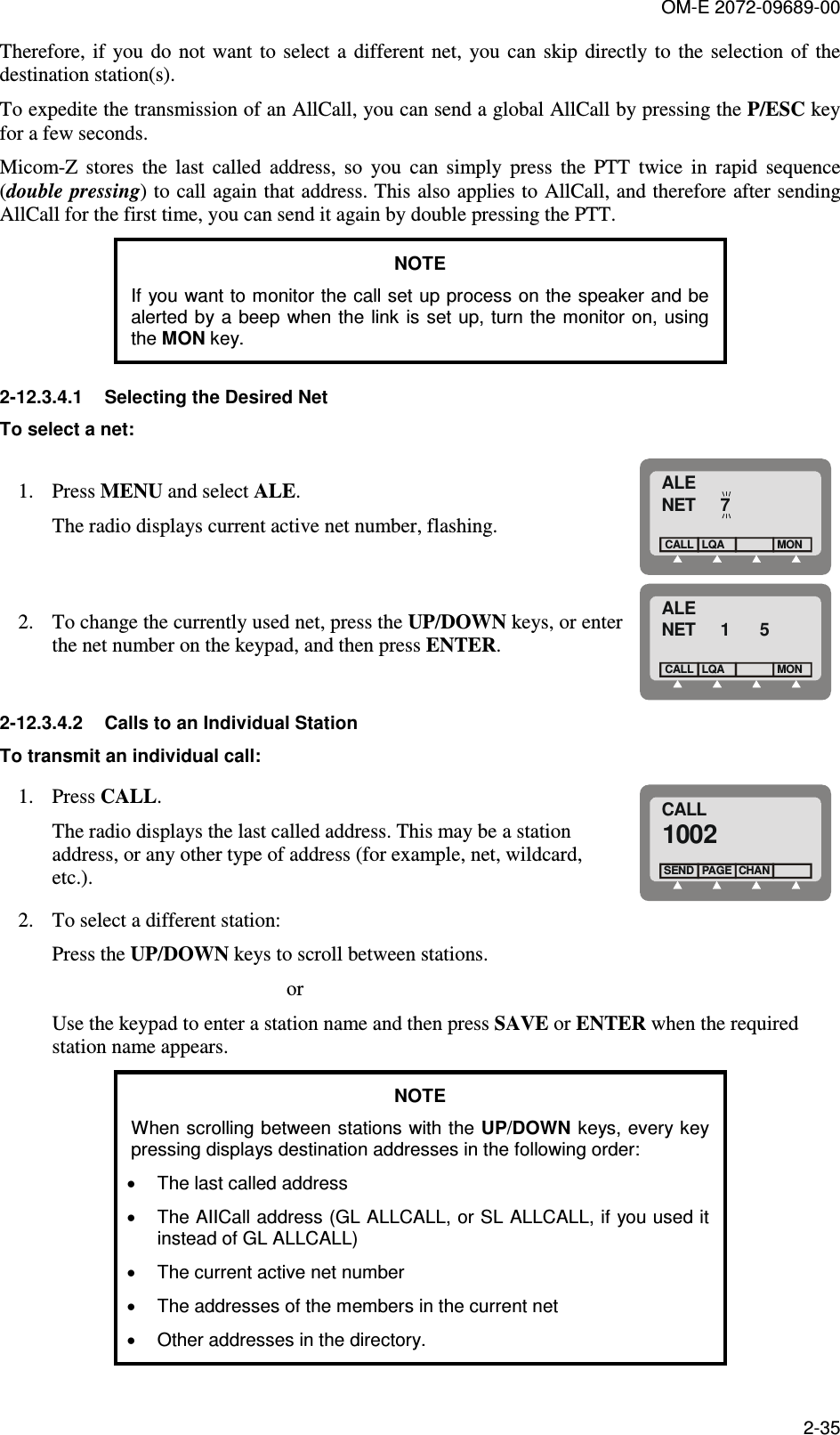
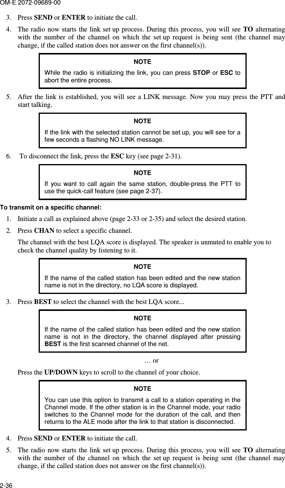
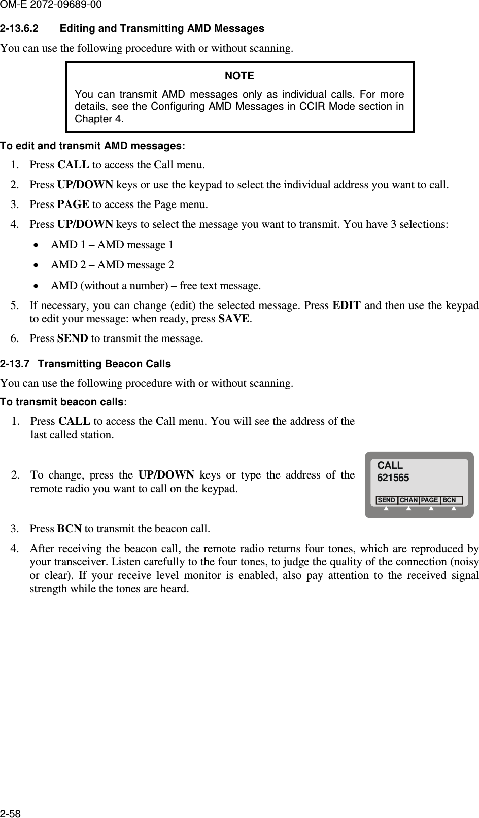
Elbit Systems Land and C4I - Tadiran Ltd. Licensed Non-Broadcast Station Transmitter - MICOM Z-Dash MICOM Z OM E RevE fp
Contents
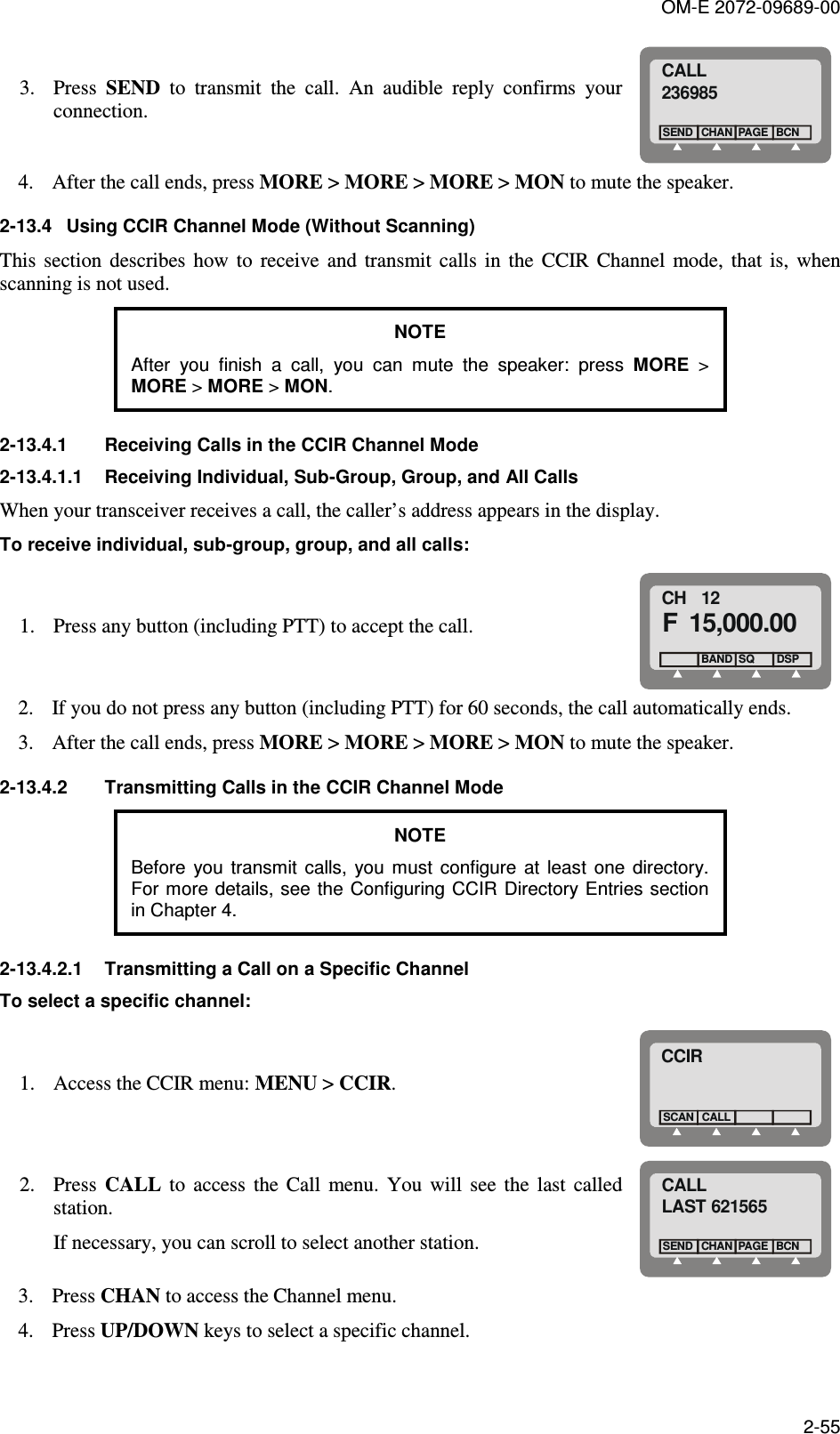
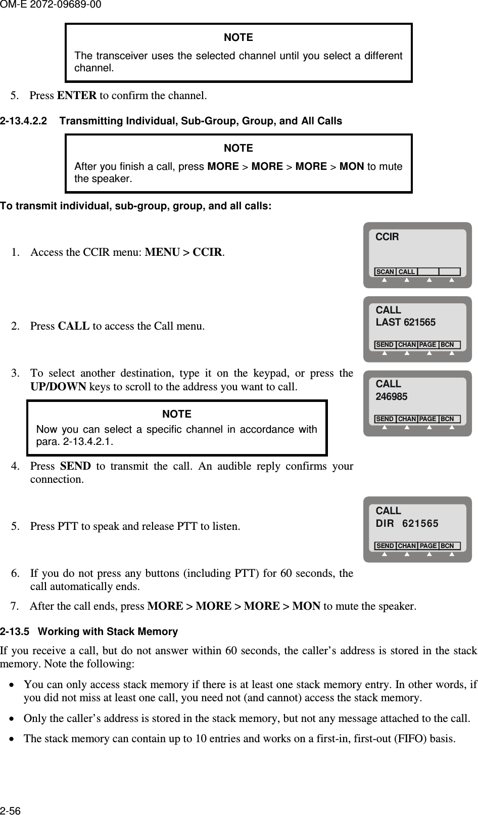
- 1. Operators Manual
- 2. Service Manual
- 3. User Manual 1
- 4. User Manual 2
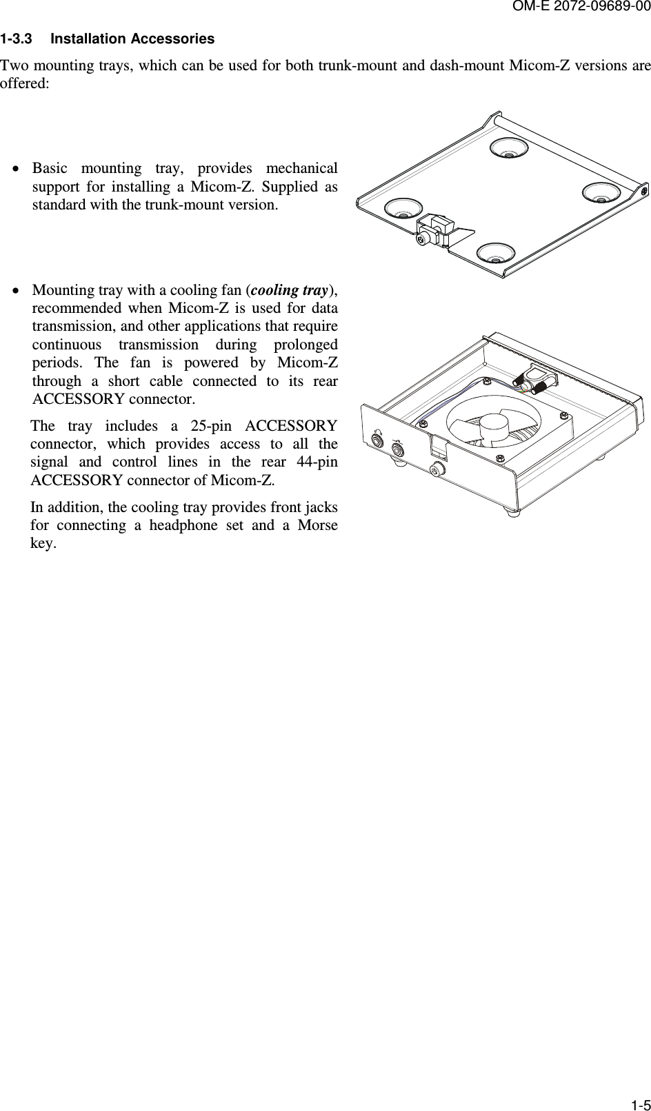
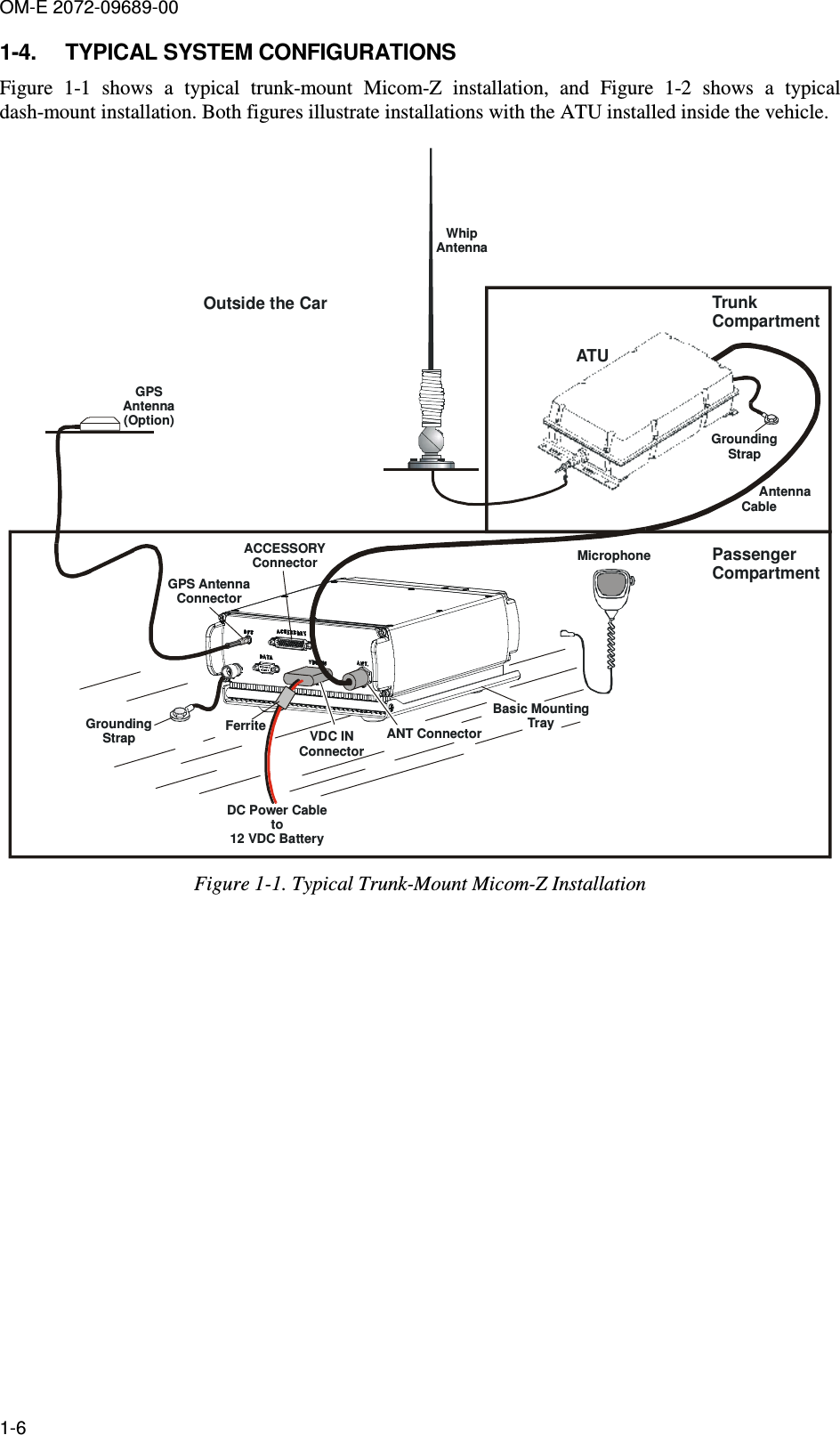
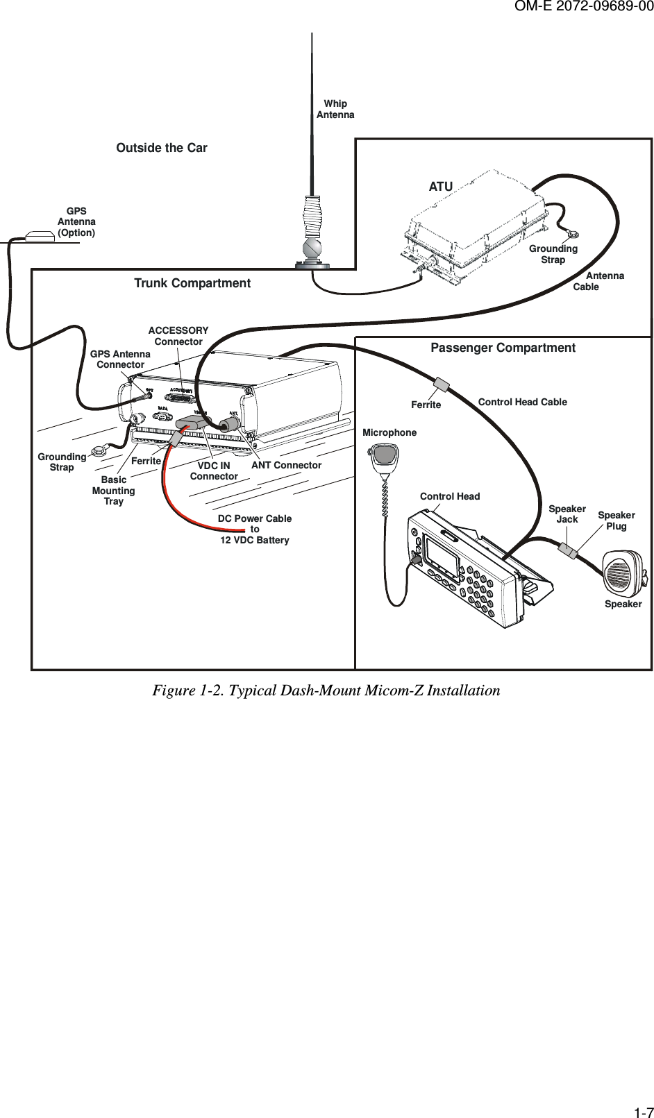
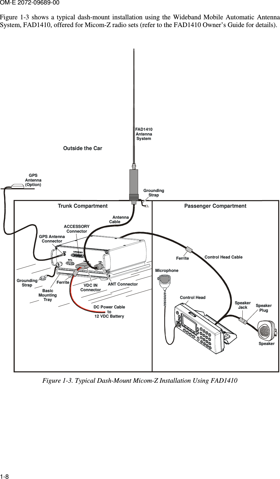
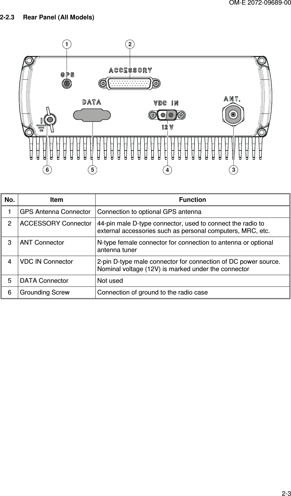
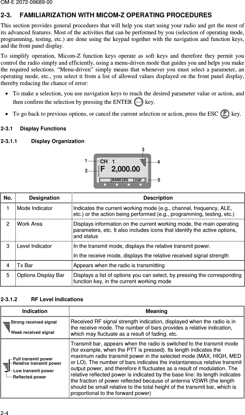
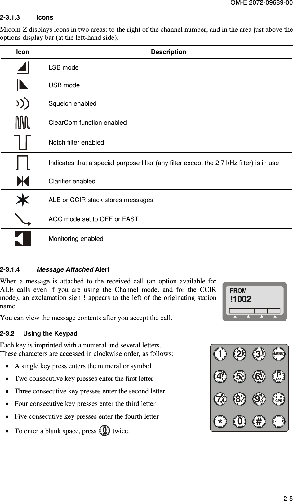
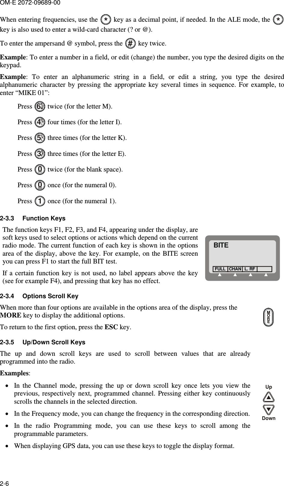
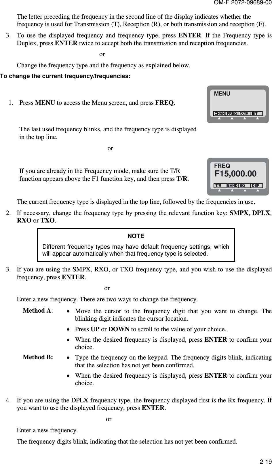
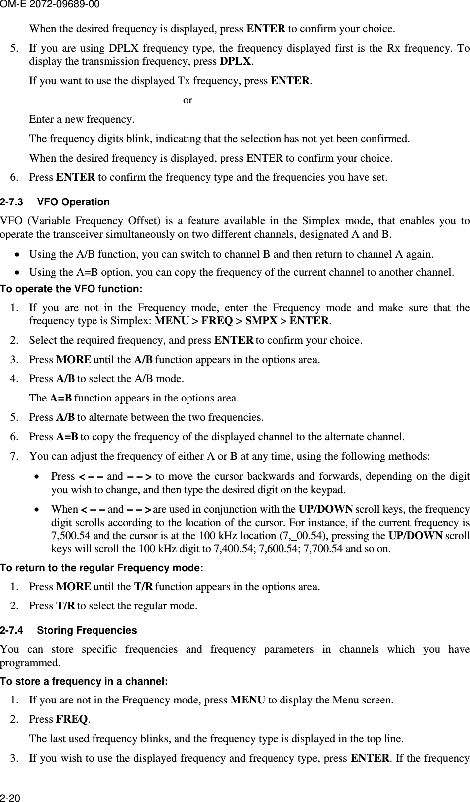
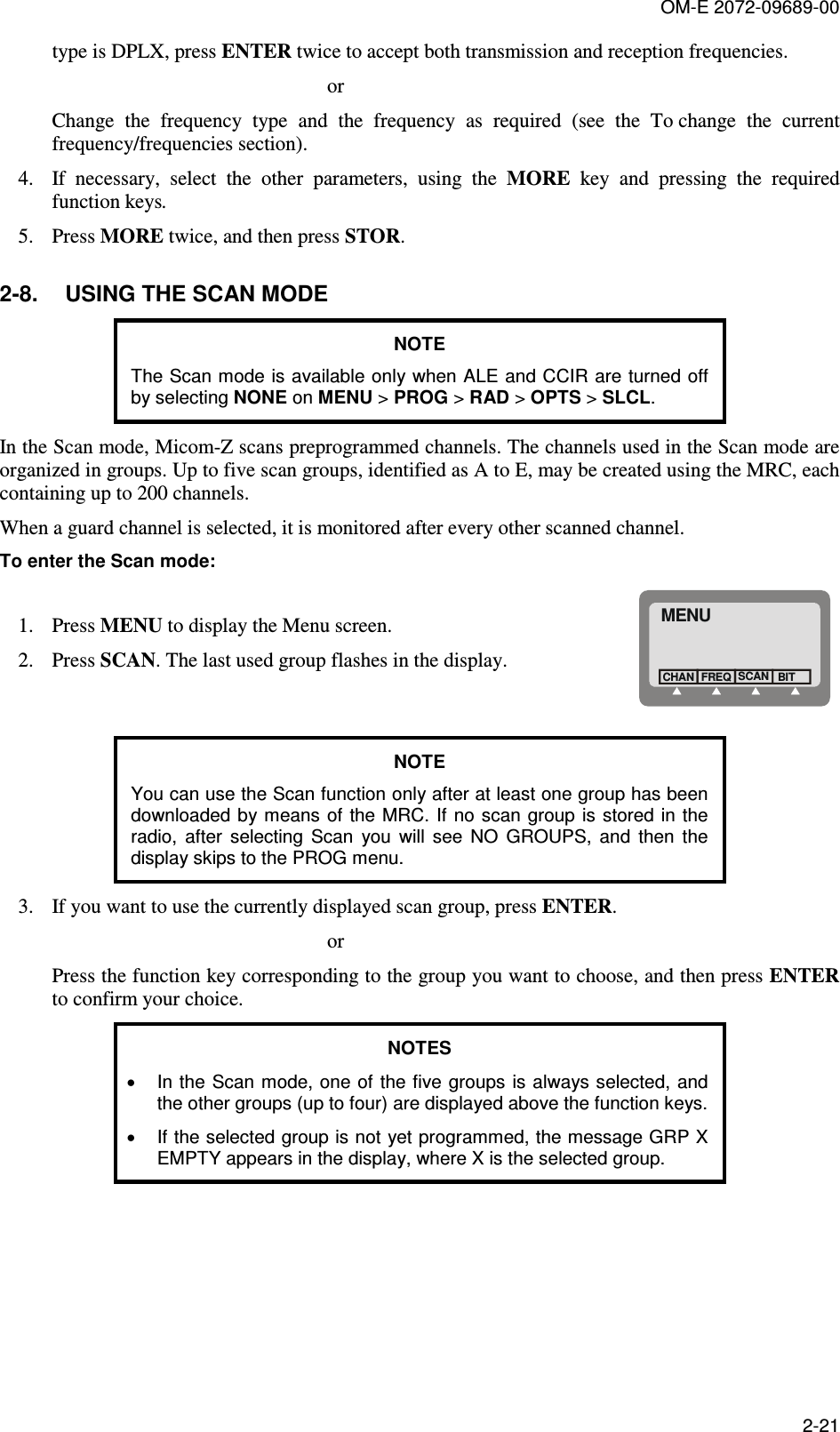
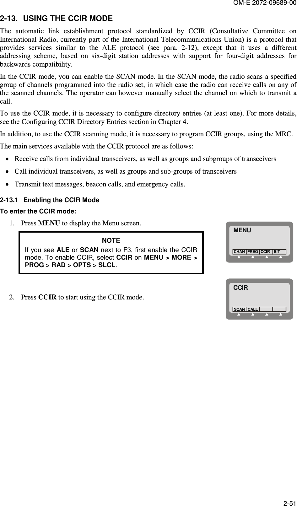
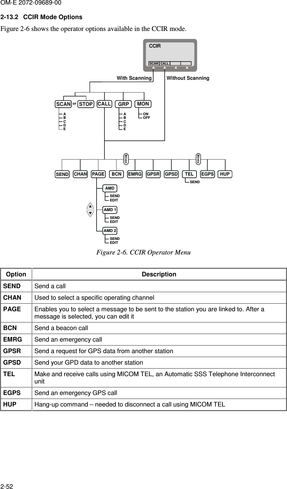
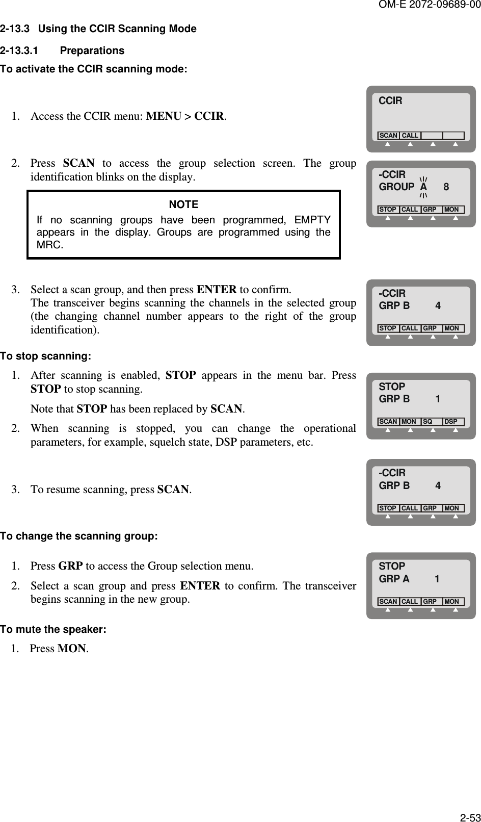
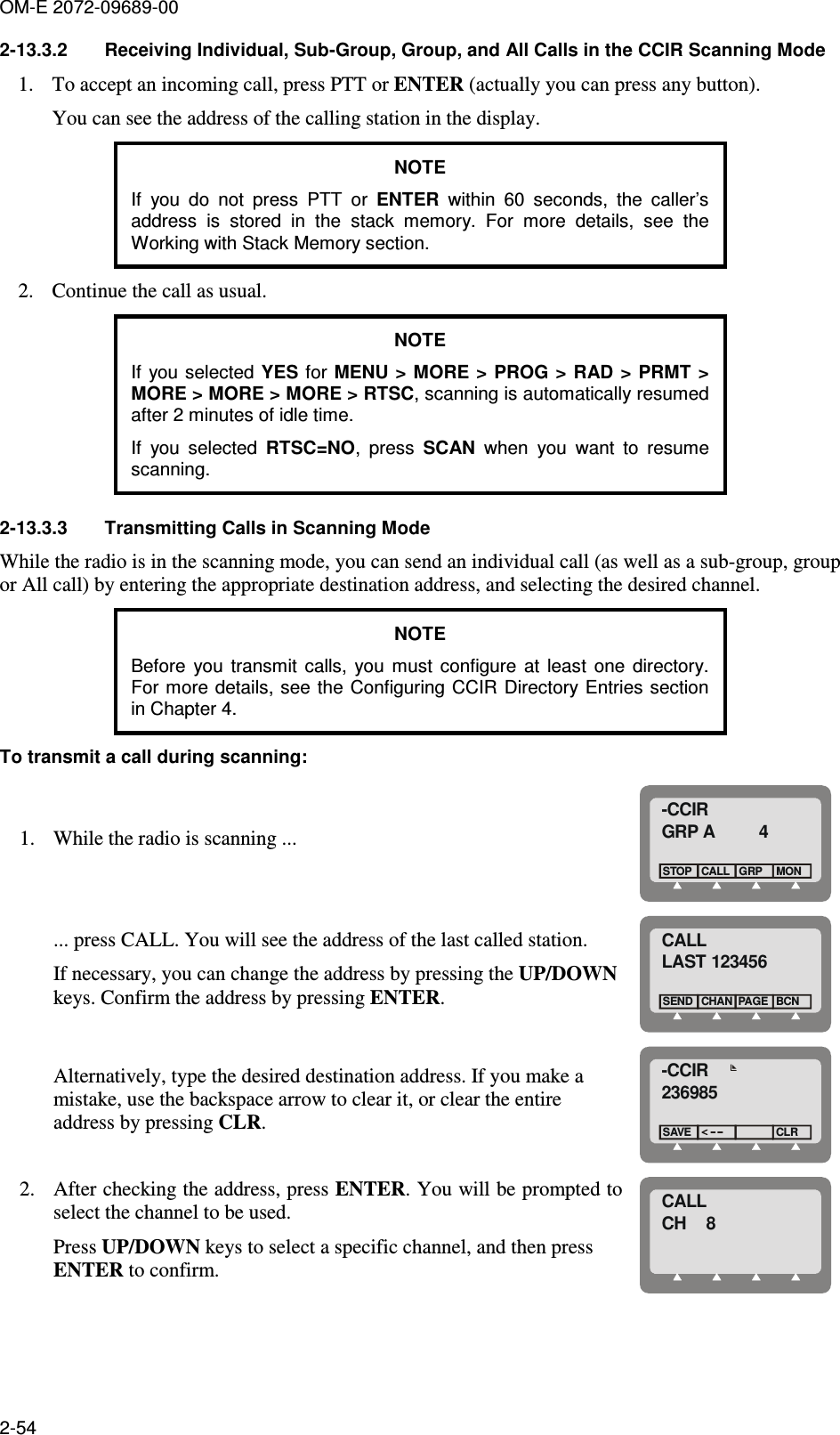
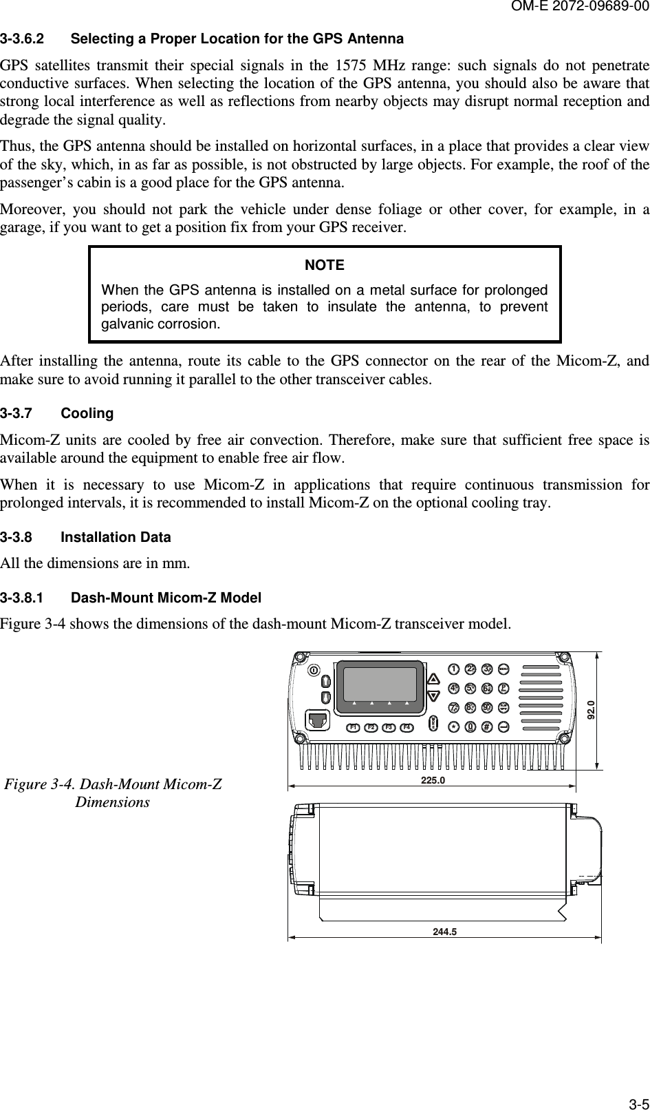
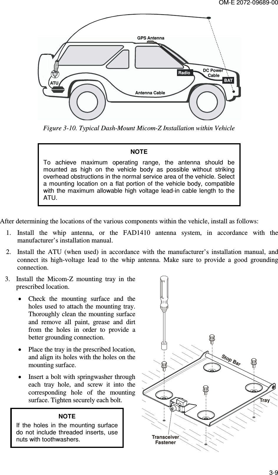
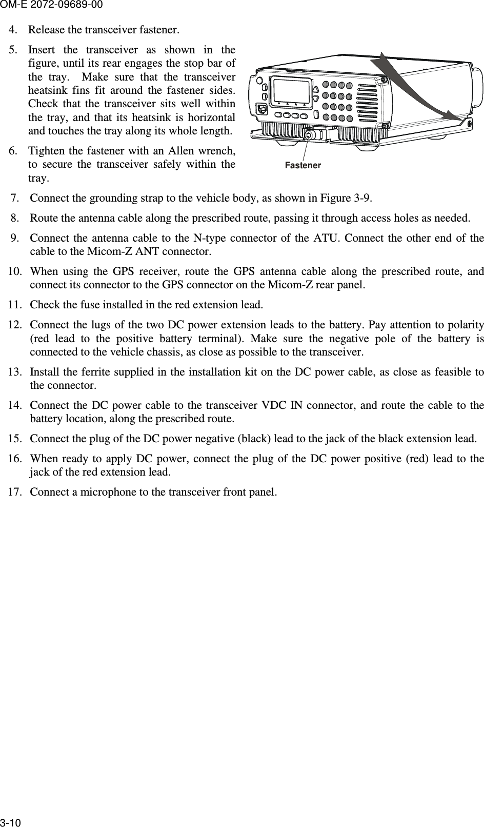
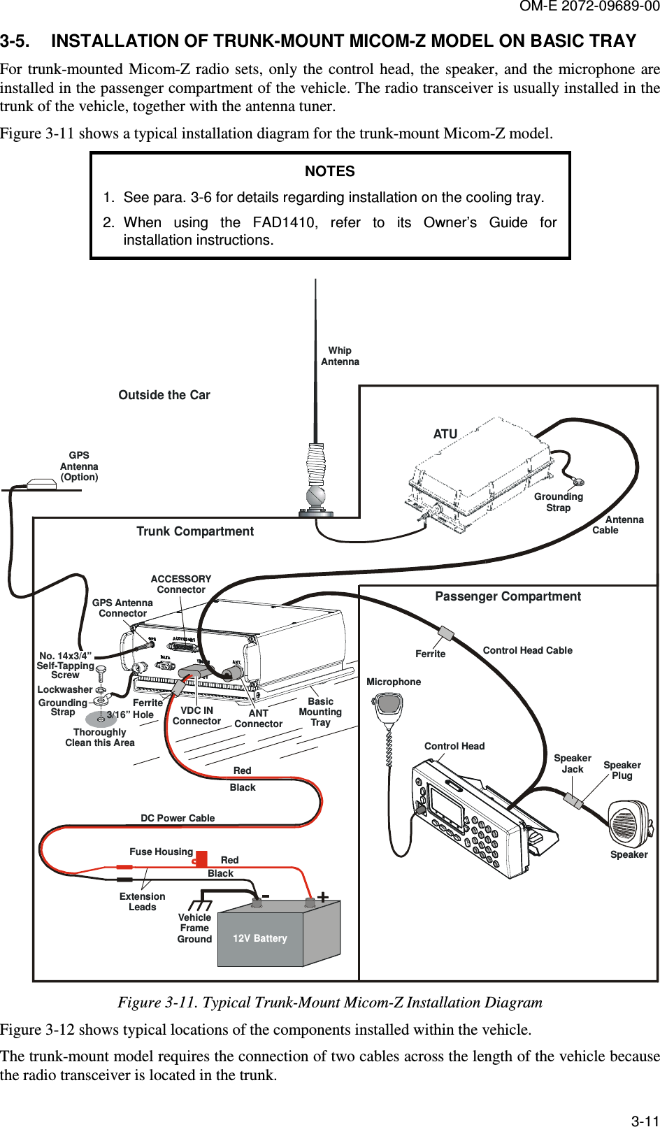
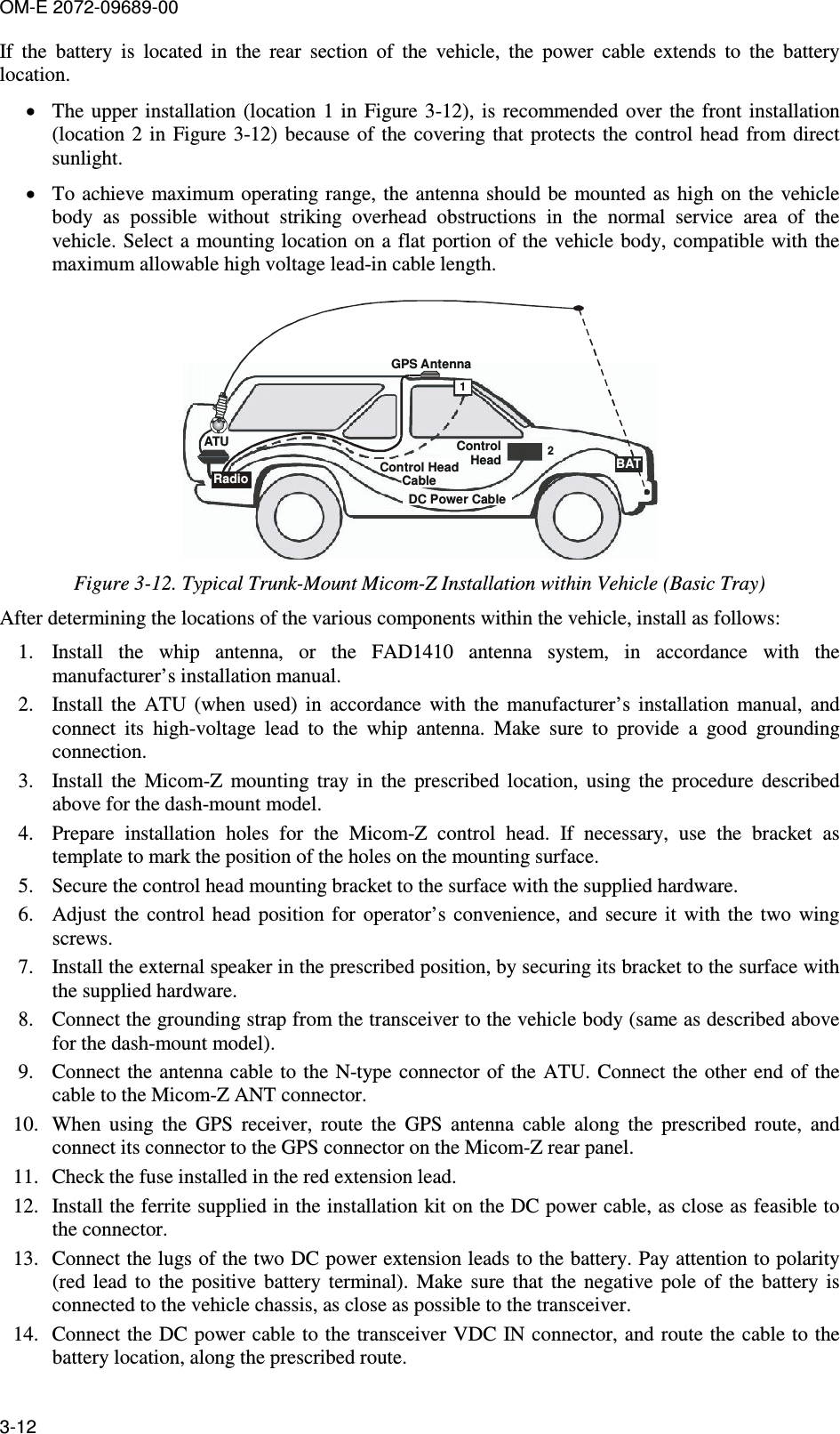
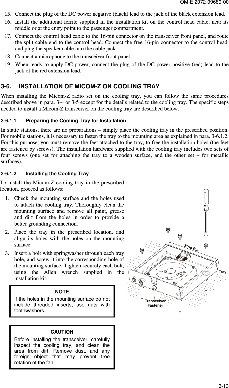
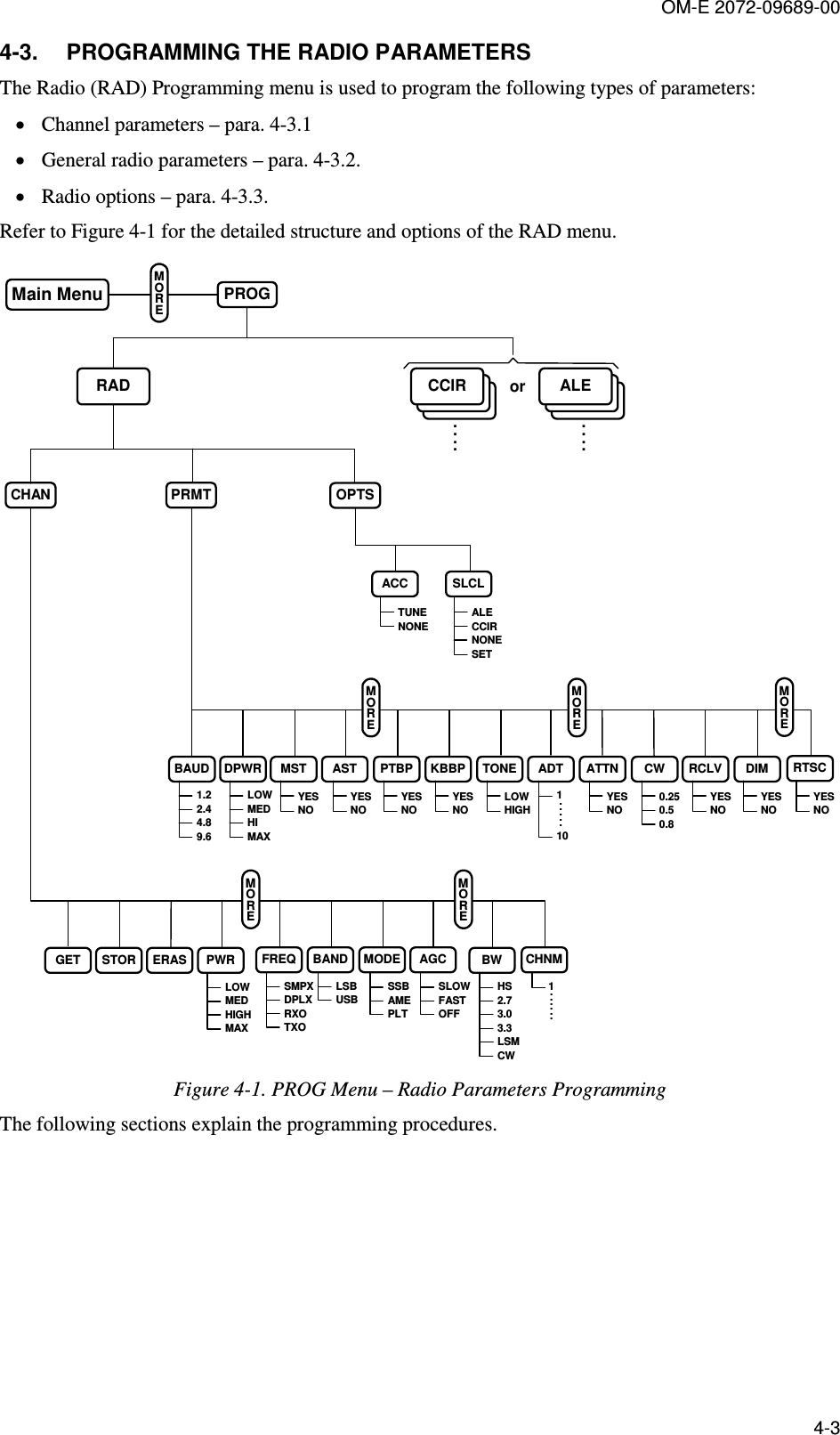
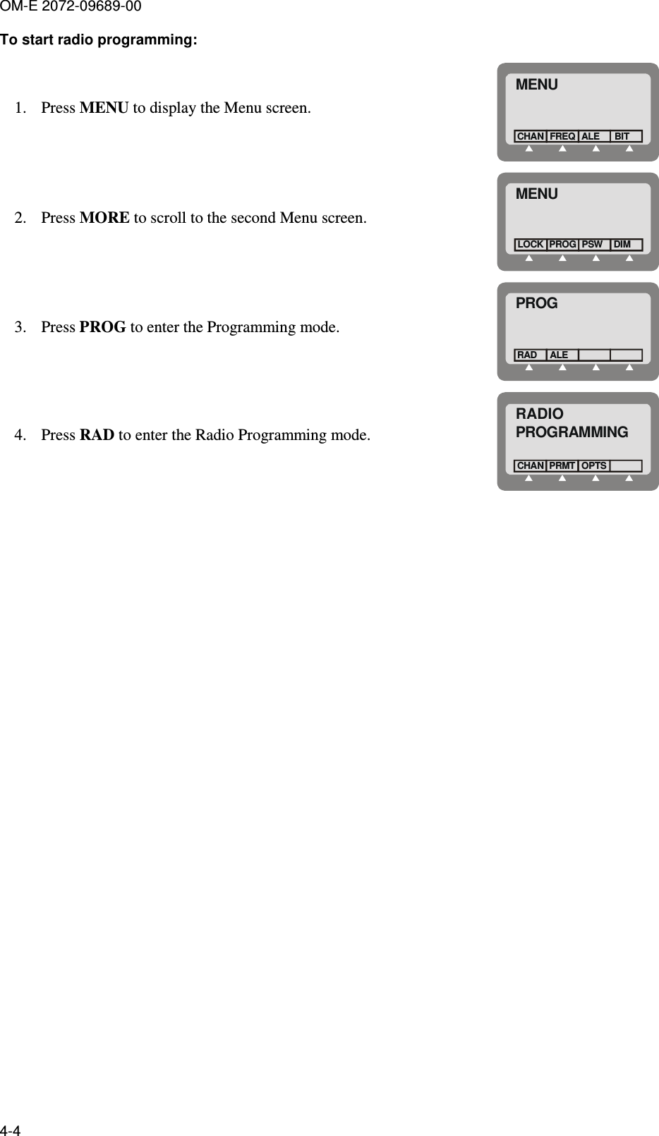
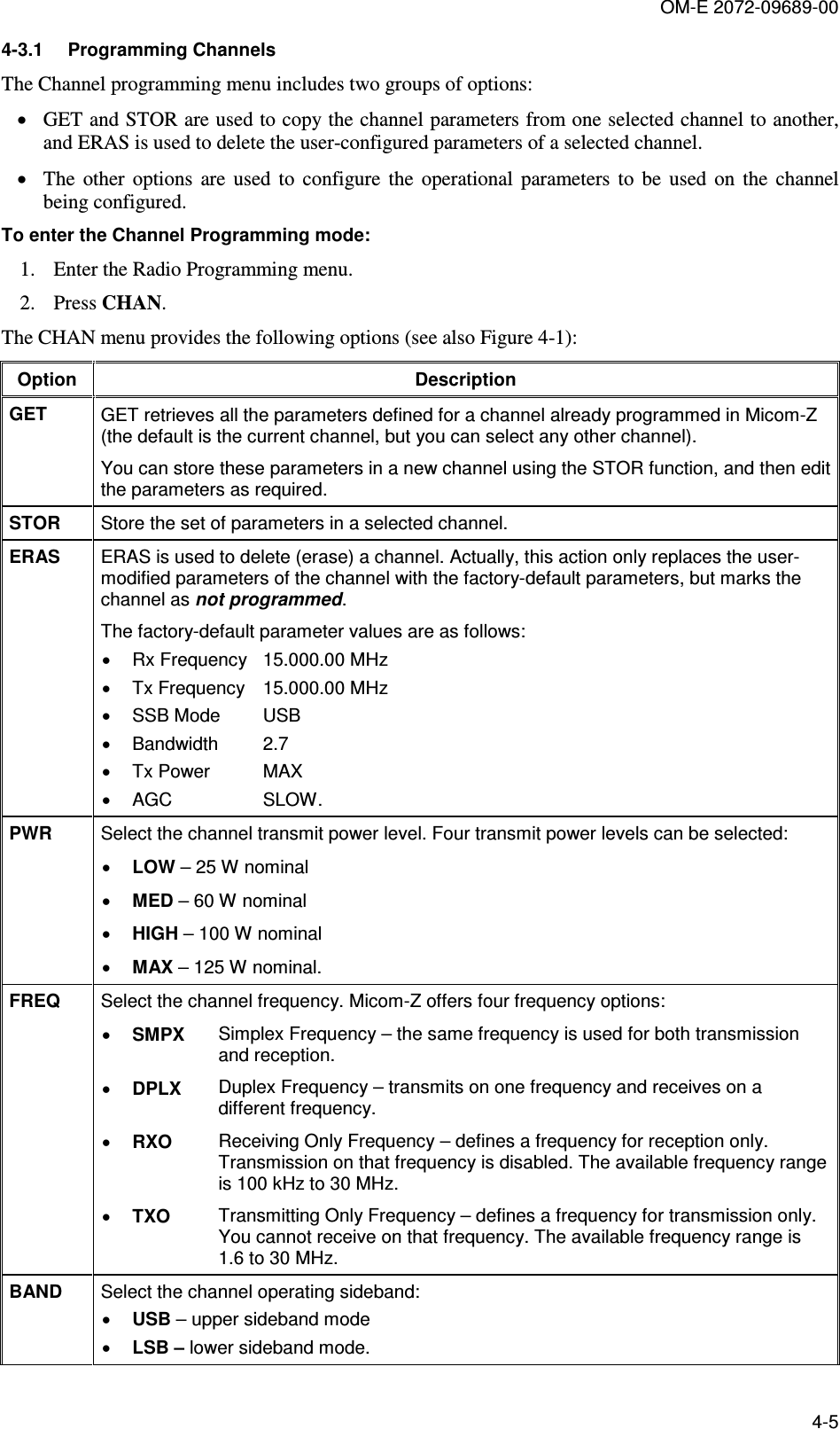
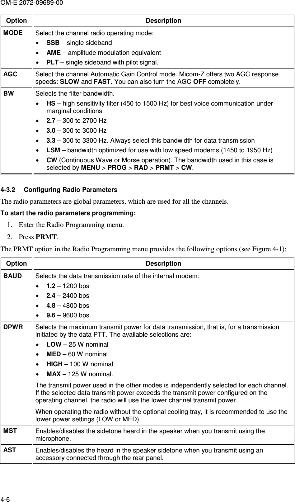
Operators Manual